EP3846587B1 - Induktionsheizvorrichtung und steuerverfahren für eine induktionsheizvorrichtung - Google Patents
Induktionsheizvorrichtung und steuerverfahren für eine induktionsheizvorrichtung Download PDFInfo
- Publication number
- EP3846587B1 EP3846587B1 EP19855331.5A EP19855331A EP3846587B1 EP 3846587 B1 EP3846587 B1 EP 3846587B1 EP 19855331 A EP19855331 A EP 19855331A EP 3846587 B1 EP3846587 B1 EP 3846587B1
- Authority
- EP
- European Patent Office
- Prior art keywords
- working coil
- frequency
- target frequency
- driving
- final driving
- Prior art date
- Legal status (The legal status is an assumption and is not a legal conclusion. Google has not performed a legal analysis and makes no representation as to the accuracy of the status listed.)
- Active
Links
Images





Classifications
-
- H—ELECTRICITY
- H05—ELECTRIC TECHNIQUES NOT OTHERWISE PROVIDED FOR
- H05B—ELECTRIC HEATING; ELECTRIC LIGHT SOURCES NOT OTHERWISE PROVIDED FOR; CIRCUIT ARRANGEMENTS FOR ELECTRIC LIGHT SOURCES, IN GENERAL
- H05B6/00—Heating by electric, magnetic or electromagnetic fields
- H05B6/02—Induction heating
- H05B6/06—Control, e.g. of temperature, of power
- H05B6/062—Control, e.g. of temperature, of power for cooking plates or the like
-
- H—ELECTRICITY
- H05—ELECTRIC TECHNIQUES NOT OTHERWISE PROVIDED FOR
- H05B—ELECTRIC HEATING; ELECTRIC LIGHT SOURCES NOT OTHERWISE PROVIDED FOR; CIRCUIT ARRANGEMENTS FOR ELECTRIC LIGHT SOURCES, IN GENERAL
- H05B6/00—Heating by electric, magnetic or electromagnetic fields
- H05B6/02—Induction heating
- H05B6/06—Control, e.g. of temperature, of power
- H05B6/062—Control, e.g. of temperature, of power for cooking plates or the like
- H05B6/065—Control, e.g. of temperature, of power for cooking plates or the like using coordinated control of multiple induction coils
-
- H—ELECTRICITY
- H05—ELECTRIC TECHNIQUES NOT OTHERWISE PROVIDED FOR
- H05B—ELECTRIC HEATING; ELECTRIC LIGHT SOURCES NOT OTHERWISE PROVIDED FOR; CIRCUIT ARRANGEMENTS FOR ELECTRIC LIGHT SOURCES, IN GENERAL
- H05B6/00—Heating by electric, magnetic or electromagnetic fields
- H05B6/02—Induction heating
- H05B6/06—Control, e.g. of temperature, of power
- H05B6/08—Control, e.g. of temperature, of power using compensating or balancing arrangements
-
- H—ELECTRICITY
- H05—ELECTRIC TECHNIQUES NOT OTHERWISE PROVIDED FOR
- H05B—ELECTRIC HEATING; ELECTRIC LIGHT SOURCES NOT OTHERWISE PROVIDED FOR; CIRCUIT ARRANGEMENTS FOR ELECTRIC LIGHT SOURCES, IN GENERAL
- H05B6/00—Heating by electric, magnetic or electromagnetic fields
- H05B6/02—Induction heating
- H05B6/10—Induction heating apparatus, other than furnaces, for specific applications
- H05B6/12—Cooking devices
- H05B6/1209—Cooking devices induction cooking plates or the like and devices to be used in combination with them
-
- H—ELECTRICITY
- H05—ELECTRIC TECHNIQUES NOT OTHERWISE PROVIDED FOR
- H05B—ELECTRIC HEATING; ELECTRIC LIGHT SOURCES NOT OTHERWISE PROVIDED FOR; CIRCUIT ARRANGEMENTS FOR ELECTRIC LIGHT SOURCES, IN GENERAL
- H05B6/00—Heating by electric, magnetic or electromagnetic fields
- H05B6/02—Induction heating
- H05B6/10—Induction heating apparatus, other than furnaces, for specific applications
- H05B6/12—Cooking devices
- H05B6/1209—Cooking devices induction cooking plates or the like and devices to be used in combination with them
- H05B6/1236—Cooking devices induction cooking plates or the like and devices to be used in combination with them adapted to induce current in a coil to supply power to a device and electrical heating devices powered in this way
-
- H—ELECTRICITY
- H05—ELECTRIC TECHNIQUES NOT OTHERWISE PROVIDED FOR
- H05B—ELECTRIC HEATING; ELECTRIC LIGHT SOURCES NOT OTHERWISE PROVIDED FOR; CIRCUIT ARRANGEMENTS FOR ELECTRIC LIGHT SOURCES, IN GENERAL
- H05B6/00—Heating by electric, magnetic or electromagnetic fields
- H05B6/02—Induction heating
- H05B6/10—Induction heating apparatus, other than furnaces, for specific applications
- H05B6/12—Cooking devices
- H05B6/1209—Cooking devices induction cooking plates or the like and devices to be used in combination with them
- H05B6/1245—Cooking devices induction cooking plates or the like and devices to be used in combination with them with special coil arrangements
-
- H—ELECTRICITY
- H05—ELECTRIC TECHNIQUES NOT OTHERWISE PROVIDED FOR
- H05B—ELECTRIC HEATING; ELECTRIC LIGHT SOURCES NOT OTHERWISE PROVIDED FOR; CIRCUIT ARRANGEMENTS FOR ELECTRIC LIGHT SOURCES, IN GENERAL
- H05B6/00—Heating by electric, magnetic or electromagnetic fields
- H05B6/02—Induction heating
- H05B6/10—Induction heating apparatus, other than furnaces, for specific applications
- H05B6/12—Cooking devices
- H05B6/1209—Cooking devices induction cooking plates or the like and devices to be used in combination with them
- H05B6/1245—Cooking devices induction cooking plates or the like and devices to be used in combination with them with special coil arrangements
- H05B6/1272—Cooking devices induction cooking plates or the like and devices to be used in combination with them with special coil arrangements with more than one coil or coil segment per heating zone
-
- H—ELECTRICITY
- H05—ELECTRIC TECHNIQUES NOT OTHERWISE PROVIDED FOR
- H05B—ELECTRIC HEATING; ELECTRIC LIGHT SOURCES NOT OTHERWISE PROVIDED FOR; CIRCUIT ARRANGEMENTS FOR ELECTRIC LIGHT SOURCES, IN GENERAL
- H05B6/00—Heating by electric, magnetic or electromagnetic fields
- H05B6/02—Induction heating
- H05B6/36—Coil arrangements
- H05B6/44—Coil arrangements having more than one coil or coil segment
-
- Y—GENERAL TAGGING OF NEW TECHNOLOGICAL DEVELOPMENTS; GENERAL TAGGING OF CROSS-SECTIONAL TECHNOLOGIES SPANNING OVER SEVERAL SECTIONS OF THE IPC; TECHNICAL SUBJECTS COVERED BY FORMER USPC CROSS-REFERENCE ART COLLECTIONS [XRACs] AND DIGESTS
- Y02—TECHNOLOGIES OR APPLICATIONS FOR MITIGATION OR ADAPTATION AGAINST CLIMATE CHANGE
- Y02B—CLIMATE CHANGE MITIGATION TECHNOLOGIES RELATED TO BUILDINGS, e.g. HOUSING, HOUSE APPLIANCES OR RELATED END-USER APPLICATIONS
- Y02B40/00—Technologies aiming at improving the efficiency of home appliances, e.g. induction cooking or efficient technologies for refrigerators, freezers or dish washers
Definitions
- the present disclosure relates to an induction heating device and a method for controlling the inducting heating device. More particularly, the present disclosure relates to an induction heating device capable of reducing an interference noise and a method for controlling the induction heating device.
- US 2010/237065 A1 describes heating device which includes a first induction coil, a second induction coil, a control panel, a power supply unit and a controlling unit.
- the control panel issues an adjusting signal.
- the power supply unit provides a first power and a second power to the first induction coil and the second induction coil, respectively.
- EP 2 506 668 A2 describes a control method of an induction heating cooker including detecting at least one heating coil occupied by a first container from among a plurality of heating coils, switching a plurality of inverter units so that a power level input by a user is applied to the detected at least one heating coil, determining, if the at least one heating coil occupied by the first container includes plural heating coils, whether or not output currents within a target output current range corresponding to the power level are present from among the output currents of the respective heating coils sensed by sensing units.
- Various types of cooking utensils are being used to heat food in homes or restaurants. Conventionally, gas ranges using gas as a fuel have come into wide use. However, recently, devices for heating a container, for example, a cooking container such as a cooking pot, using electricity without using gas have come into use.
- a method of heating a container using electricity is divided into a resistance heating method and an induction heating method.
- the resistance heating method is a method of heating a container by transferring heat generated when a current is passed through a metal-resistant wire or a nonmetallic heating element such as silicon carbide to the container via radiation or conduction.
- the induction heating method is a method of generating an eddy current in a container that is made of a metal component by using a magnetic field that occurs around a working coil when a predetermined magnitude of high-frequency power is applied to the working coil so that the container itself is heated.
- a principle of the induction heating method will be described in more detail as follows. First, as power is applied to the induction heating device, a predetermined magnitude of high-frequency voltage is applied to the working coil. Accordingly, an induction magnetic field occurs around the working coil disposed in the induction heating device. When a magnetic line of force of the induction magnetic field passes through the bottom of the container including a metal component that is placed on the induction heating device, an eddy current occurs in the bottom of the container. When the eddy current flows through the bottom of the container, the container itself is heated.
- An induction heating device that is currently being used includes two or more heating areas and two or more working coils corresponding to the heating areas. For example, when a user who uses an induction heating device having two heating areas wishes to respectively place containers on the two heating areas and performs cooking by using the containers simultaneously, power for driving is supplied to each of the two working coils. As power is supplied to each working coil, each working coil generates a resonant frequency.
- an interference noise caused is generated by driving of the working coils.
- the interference noise generated as described above causes great inconvenience to the user who uses the induction heating device, and may cause the user to suspect a failure of the induction heating device.
- Korean Patent Registration No. 10-1735754 discloses that, in an induction heating device having a plurality of working coils, a switching element connected to each induction coil is sequentially turned on/off in a time division manner, and thereby an interference noise is prevented even when the plurality of working coils are driven simultaneously.
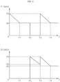
- FIG. 1 is a graph illustrating a frequency control method for reducing an interference noise of an induction heating device according to the related art.
- FIG. 1 illustrates a driving process of an induction heating device having two working coils.
- f1 represents a driving frequency of a first working coil
- f2 represents a driving frequency of a second working coil
- t represents time.
- the first working coil may operate at a driving frequency corresponding to the driving command issued by the user (for example, 30 kHz) so as to provide an output corresponding to the driving command issued by the user.
- the user may issue a driving command for a second working coil.
- the second working coil may start to be driven at a preset frequency (for example, 70 kHz) at a time point T1.
- the first working coil may be continuously driven at the existing driving frequency (30 kHz).
- the induction heating device may adjust a driving frequency of the second working coil until the driving frequency of the second working coil reaches a frequency for allowing the second working coil to supply an output corresponding to the driving command for the second working coil, that is, a target frequency (for example, 30 kHz).
- a target frequency for example, 30 kHz.
- both the first working coil and the second working coil may maintain a driving state thereof from the time point T1 to the time point T2 after the driving command for the second working coil is inputted.
- a difference value between the driving frequency of the first working coil and the driving frequency of the second working coil may be included in an audible frequency band (2 k to 15 kHz).
- an interference noise is generated from the time point T1 to the time point T2 by driving of the second working coil.
- An aspect of the present disclosure is to provide an induction heating device capable of reducing an interference noise that may occur when two or more working coils perform a heating operation, and a method for controlling the induction heating device.
- An aspect of the present disclosure is to provide an induction heating device capable of reducing an interference noise that may occur in the process of driving a working coil at a determined target frequency after the target frequency of the working coil is determined.
- the method for controlling an induction heating device may include determining a first target frequency of a first working coil corresponding to a driving command for the first working coil, determining a second target frequency of a second working coil corresponding to a driving command for the second working coil, determining a final driving frequency of the first working coil and a final driving frequency of the second working coil based on the first target frequency and the second target frequency, respectively, driving the first working coil and the second working coil simultaneously at a preset second adjustment frequency, and adjusting a driving frequency of the first working coil to the final driving frequency of the first working coil and adjusting a driving frequency of the second working coil to the final driving frequency of the second working coil, respectively.
- the method for controlling an induction heating device may further include, when the driving command for the second working coil is received while the first working coil is being driven at the first target frequency, stopping driving of the first working coil, and driving the second working coil at a preset first adjustment frequency.
- the determining the final driving frequency of the first working coil and the final driving frequency of the second working coil based on the first target frequency and the second target frequency may include calculating a difference value between the first target frequency and the second target frequency, and determining the final driving frequency of the first working coil and the final driving frequency of the second working coil according to a comparison result between the difference value and a preset reference value.
- the final driving frequency of the first working coil and the final driving frequency of the second working coil may be set to be equal to each other.
- the final driving frequency of the first working coil and the final driving frequency of the second working coil may be set as any one among the first target frequency and the second target frequency.
- a difference between the final driving frequency of the first working coil and the final driving frequency of the second working coil may be set to correspond to a preset noise avoidance setting value.
- a value obtained by increasing a larger value among the first target frequency and the second target frequency by the preset noise avoidance setting value and a smaller value among the first target frequency and the second target frequency may be set as the final driving frequency of the first working coil and the final driving frequency of the second working coil, respectively.
- the final driving frequency of the first working coil when the difference value is equal to or greater than a second reference value, the final driving frequency of the first working coil may be set as the first target frequency, and the final driving frequency of the second working coil may be set as the second target frequency.
- an induction heating device may include a first working coil disposed to correspond to a first heating area, a second working coil disposed to correspond to a second heating area, and a control unit configured to adjust driving frequencies of the first working coil and the second working coil according to a driving command inputted by a user.
- the control unit may determine a first target frequency of a first working coil corresponding to a driving command for the first working coil, determine a second target frequency of a second working coil corresponding to a driving command for the second working coil, determine a final driving frequency of the first working coil and a final driving frequency of the second working coil based on the first target frequency and the second target frequency, respectively, drive the first working coil and the second working coil simultaneously at a second adjustment frequency, and adjust a driving frequency of the first working coil to the final driving frequency of the first working coil and adjust a driving frequency of the second working coil to the final driving frequency of the second working coil, respectively.
- control unit when the driving command for the second working coil is received while the first working coil is being driven at the first target frequency, the control unit may stop driving of the first working coil and drive the second working coil at a preset first adjustment frequency.
- control unit may calculate a difference value between the first target frequency and the second target frequency, and determine the final driving frequency of the first working coil and the final driving frequency of the second working coil according to a comparison result between the difference value and a preset reference value.
- the final driving frequency of the first working coil and the final driving frequency of the second working coil may be set to be equal to each other.
- the final driving frequency of the first working coil and the final driving frequency of the second working coil may be set as any one among the first target frequency and the second target frequency.
- a difference between the final driving frequency of the first working coil and the final driving frequency of the second working coil may be set to correspond to a preset noise avoidance setting value.
- a value obtained by increasing a larger value among the first target frequency and the second target frequency by a preset noise avoidance setting value, and a smaller value among the first target frequency and the second target frequency may be set as the final driving frequency of the first working coil and the final driving frequency, respectively.
- the final driving frequency of the first working coil when the difference value is equal to or greater than a second reference value, the final driving frequency of the first working coil may be set as the first target frequency, and the final driving frequency of the second working coil may be set as the second target frequency.
- FIG. 2 is a perspective view illustrating an induction heating device according to an embodiment of the present disclosure.
- an induction heating device 10 may include a case 102 constituting a main body, and a cover plate 110 coupled to the case 102 to seal the case 102.
- a lower surface of the cover plate 110 may be coupled to an upper surface of the case 102 to seal a space formed inside the case 102 from the outside.
- An upper surface of the cover plate 110 may be provided with an upper plate portion 105 on which a container for cooking food may be placed.
- the upper plate portion 105 may be made of various materials, for example, a tempered glass material such as ceramic glass.
- Working coils 103, 104, and 106a and 106b for heating a container may be disposed in an inner space of the case 102 formed by coupling of the cover plate 110 and the case 203. More specifically, a first working coil 103, a second working coil 104, and third working coils 106a and 106b may be disposed inside the case 102.
- the first working coil 103 and the second working coil 104 each may have a rectangular shape with curved corners, and the third working coils 106a and 106b may have a circular shape, but a shape of each working coil may vary depending on the embodiment.
- the number and arrangement of working coils provided in the induction heating device 10 may vary depending on the embodiment.
- the third working coils 106a and 106b may be composed of two coils, that is, an inner coil 106a and an outer coil 106b.
- FIG. 1 illustrates an embodiment in which two coils constitute the third working coil, but the number of coils constituting the third working coil and the number of coils constituting the inner coil and the outer coil may vary depending on the embodiment.
- the third working coil may be composed of four coils.
- two coils disposed inside the third working coil may be defined as an inner coil, and the other two coils disposed outside may be defined as an outer coil.
- three coils disposed inside the third working coil may be defined as an inner coil, and the other one coil disposed outside may be defined as an outer coil.
- a first heating area 142, a second heating area 144, and a third heating area 146 may be displayed on a surface of the upper plate portion 105 of the cover plate 110 at positions respectively corresponding to positions of the first working coil 103, the second working coil 104, and the third working coils 106a and 106b such that the user matches a position of the container with a position of the first working coil 103, the second working coil 104, or the third working coils 106a and 106b.
- the inner space of the case 102 may be provided with an interface unit 108 having a function of allowing a user to apply power, adjusting outputs of the working coils 103, 104, and 106a and 106b, or displaying information related to the induction heating device 10.
- the interface unit 108 is implemented as a touch panel capable of both inputting information by means of touch and displaying information, but the interface unit 108 may be implemented as a different form or structure depending on the embodiment.
- the upper plate portion 105 of the cover plate 110 may be provided with a manipulation area 118 at a position corresponding to a position of the interface unit 108.
- a specific character or image for a user's manipulation or for displaying information may be displayed.
- the user may perform a desired operation by manipulating (for example, touching) a specific point of the manipulation area 118 with reference to the character or image displayed on the manipulation area 118.
- various types of information outputted by the interface unit 114 may be displayed via the manipulation area 118 according to the user's manipulation or an operation of the induction heating device 10.
- a power module (not illustrated) for supplying power to the working coils 103, 104, and 106a and 106b or the interface unit 114 may be disposed in the inner space of the case 102.
- the power module may be electrically connected to the working coils 103, 104, and 106a and 106b or the interface unit 108, and may convert power applied from an external power source into power suitable for driving of the working coils 103, 104, and 106a and 106b or the interface unit 108, and supply the converted power to the working coils 103, 104, and 106a and 106b or the interface unit 108.
- FIG. 1 illustrates an embodiment in which three working coils 103, 104, and 106a and 106b are disposed in the inner space of the case 102. In some embodiments, one working coil or four working coils may be disposed in the inner space of the case 102.
- a control unit may be disposed in the inner space of the case 102.
- the control unit may control power supply to the working coils 103, 104, and 106a and 106b based on driving of the power module according to a user's command (heating command, heating end command, thermal power control command, and the like) inputted via the interface unit 108.
- the user may place the container on a desired heating area among the first heating area 142, the second heating area 144, and the third heating area 146, and then may issue a heating command with a thermal power setting for the heating area on which the container is placed.
- the user's heating command inputted via the manipulation area 118 may be inputted to the control unit (not illustrated) as a driving command for a working coil corresponding to the heating area on which the user places the container.
- the control unit (not illustrated) receiving the driving command may drive the working coil, which is a target of the driving command, to perform a heating operation on the container.
- FIG. 3 is a circuit diagram illustrating a working coil and a power module of an induction heating device according to an embodiment of the present disclosure.
- FIG. 3 is a circuit diagram illustrating a case where an induction heating device according to an embodiment of the present disclosure includes two working coils, that is, a first working coil 103 and a second working coil 104.
- the induction heating device according to an embodiment of the present disclosure may have two or more working coils, and a method for controlling the induction heating device described below may be applied to an induction heating device having two or more working coils in the same manner.
- the induction heating device may include two power modules, that is, a first power module 202 and a second power module 204.
- the first power module 202 and the second power module 204 may convert alternating current (AC) power supplied from an external power source 30 to supply power for driving each of the first working coil 103 and the second working coil 104.
- AC alternating current
- the first power module 202 may include a rectification unit 302 and a smoothing unit 304.
- the rectification unit 302 may rectify and output AC power supplied from the external power source 30.
- the smoothing unit 304 may include a first inductor L1 and a first capacitor C1, and may convert the power outputted from the rectification unit 302 into direct current (DC) power to output the DC power.
- the second power module 204 also may include a rectification unit 306 and a smoothing unit 308.
- the rectification unit 306 may rectify and output AC power supplied from the external power source 30.
- the smoothing unit 308 may include a second inductor L2 and a fourth capacitor C4, and may convert the power outputted from the rectification unit 306 into DC power to output the DC power.
- the first power module 202 may include a plurality of switching elements SW1 and SW2 and a plurality of capacitors C2 and C3.
- the first switching element SW 1 and the second switching element SW2 may be connected in series with each other, and may repeatedly perform turn-on and turn-off operations by means of a first switching signal S 1 and a second switching signal S2 outputted from a first driving unit 34.
- the turn-on and turn-off operations of the switching elements are referred to as "switching operation”.
- a second capacitor C2 and a third capacitor C3 may be connected in series with each other.
- the first switching element SW1, the second switching element SW2, the second capacitor C2, and the third capacitor C3 may be connected in parallel to each other.
- the first working coil 103 may be connected between a connection point between the first switching element SW1 and the second switching element SW2 and a connection point between the second capacitor C2 and the third capacitor C3.
- AC power may be supplied to the first working coil 103 to perform induction heating.
- the second power module 204 also may include a plurality of switching elements SW3 and SW4 and a plurality of capacitors C5 and C6.
- the third switching element SW3 and the fourth switching element SW4 may be connected in series with each other, and may repeatedly perform turn-on and turn-off operations, that is, a switching operation by means of a third switching signal S3 and a fourth switching signal S4 outputted from a second driving unit 36.
- a fifth capacitor C5 and a sixth capacitor C6 may be connected in series with each other.
- the third switching element SW3, the fourth switching element SW4, the fifth capacitor C5, and the sixth capacitor C6 may be connected in parallel to each other.
- the second working coil 104 may be connected between a connection point between the third switching element SW3 and the fourth switching element SW4 and a connection point between the fifth capacitor C5 and the sixth capacitor C6.
- AC power may be supplied to the second working coil 104 to perform induction heating.
- the first driving unit 34 may apply the first switching signal S1 and the second switching signal S2 to the first switching element SW1 and the second switching element SW2 included in the first power module 202, respectively.
- the second driving unit 36 may apply the third switching signal S3 and the fourth switching signal S4 to the third switching element SW3 and the fourth switching element SW4 included in the second power module 204, respectively.
- a control unit 32 may apply a control signal to each of the first driving unit 34 and the second driving unit 36 to control outputs of the switching signals S1 and S2 applied by the first driving unit 34 and outputs of the switching signals S3 and S4 applied by the second driving unit 36.
- the control unit 32 may adjust switching frequencies of the first switching signal S1 and the second switching signal S2 applied by the first driving unit 34, and switching frequencies of the third switching signal S3 and the fourth switching signal S4 applied by the second driving unit 36 to respectively adjust a driving frequency of the first working coil 103 and a driving frequency of the second working coil 104.
- An amount of power supplied to the first working coil 103 or the second working coil 104 may vary depending on the driving frequency adjusted by the control unit 32. Accordingly, the driving frequency of the first working coil 103 or the second working coil 104 and an output amount of the first working coil 103 or the second working coil 104 may vary.
- Voltage detection units 212 and 222 may measure a magnitude of a voltage inputted to the first power module 202, that is, a magnitude of an input voltage.
- current detection units 214 and 224 may measure a magnitude of a current inputted to the first and second working coils 103 and 104, that is, a magnitude of an input current.
- the control unit 32 may receive the magnitude of the input voltage from the voltage detection units 212 and 222, and may receive the magnitude of the input current from the current detection units 214 and 224.
- the control unit 32 may calculate an output amount of the first working coil 103 and the second working coil 104, that is, an amount of power supplied by the first working coil 103 and the second working coil 104 by using the magnitudes of the received input voltage and the input current.
- a method in which the control unit 32 calculates an amount of power of each working coil by using the magnitudes of the input voltage and the input current is the same as a conventional method, and accordingly a detailed description thereof is omitted.
- a user may place a container on a desired heating area, and then may issue a heating command with a thermal power setting for the heating area on which the container is placed via the manipulation area 118.
- the user's heating command inputted via the manipulation area 118 may be inputted to the control unit 32 as a driving command for a working coil corresponding to the heating area on which the user places the container.
- the control unit 32 receiving the driving command may drive the working coil, which is a target of the driving command, to perform a heating operation on the container.
- an interference noise phenomenon described above may not occur.
- the interference noise phenomenon described above may occur according to a magnitude of a driving frequency of each working coil.
- the control unit 32 of the induction heating device may determine a target frequency of each working coil when a user inputs a driving command for another working coil while one working coil is being driven, and may perform frequency control so as to reduce an interference noise based on the determined target frequency of each working coil.
- the target frequency of each working coil means a driving frequency corresponding to a driving command issued with respect to each working coil.
- the target frequency means a driving frequency of each working coil for allowing each working coil to supplying thermal power or an output desired by the user via the driving command.
- the control unit 32 of the induction heating device when the control unit 32 of the induction heating device according to the present disclosure is requested to drive the second working coil 104 in a state where the first working coil 103 is being driven at a first target frequency, the control unit 32 may determine a second target frequency of the second working coil 104. The control unit 32 may determine a driving mode (coupling mode, separation mode, normal mode) for reducing a noise of the induction heating device based on the determined second target frequency and the first target frequency.
- a driving mode coupling mode, separation mode, normal mode
- the control unit 32 may determine a final driving frequency for reducing interference noises of the first working coil 103 and the second working coil 104 based on the driving mode determined as described above.
- the control unit 32 may drive each working coil based on the determined final driving frequency, thereby reducing interference noises generated when the two working coils are driven simultaneously.
- f1 represents a driving frequency of the first working coil 103
- f2 represents a driving frequency of the second working coil 104
- T represents time
- FIG. 4 is a graph illustrating a process of controlling driving frequencies of a first working coil and a second working coil when an induction heating device according to an embodiment of the present disclosure is driven in a coupling mode.
- FIG. 5 is a graph illustrating a process of controlling driving frequencies of a first working coil and a second working coil when an induction heating device according to an embodiment of the present disclosure is driven in a separation mode.
- FIG. 6 is graph illustrating a process of controlling driving frequencies of a first working coil and a second working coil when an induction heating device according to an embodiment of the present disclosure is driven in a normal mode.
- a user's driving command for the first working coil 103 may be inputted to the control unit 32 in a state where the second working coil 104 is not yet driven.
- the control unit 32 receiving the driving command for the first working coil 103 may drive the first working coil 103 at a preset first adjustment frequency (for example, 70 kHz).
- a magnitude of the first adjustment frequency may be set differently depending on the embodiment. Accordingly, at a time point 0, the first working coil 103 may start to be driven at 70 kHz, which is the first adjustment frequency.
- the control unit 32 may search for a target frequency of the first working coil 103 (first target frequency) by adjusting the driving frequency of the first working coil 103 such that the first working coil 103 can supply an output corresponding to thermal power set by the user with respect to the first working coil 103.
- the control unit 32 may calculate an amount of power supplied by the first working coil 103 while gradually reducing the driving frequency of the first working coil 103 from the first adjustment frequency.
- the amount of power supplied by the first working coil 103 may be calculated based on an input voltage value transmitted from the voltage detection unit 212 and an input current value transmitted from the current detection unit 214.
- the control unit 32 may determine a frequency value of the time point T1 (for example, 40 kHz) when the amount of power of the first working coil 103 measured while reducing the driving frequency corresponds to an output requested by the user via the driving command. Accordingly, the first working coil 103 may be driven at the first target frequency (40 kHz).
- a frequency value of the time point T1 for example, 40 kHz
- the control unit 32 may receive a driving command for the second working coil 104.
- the control unit 32 may stop driving of the first working coil 103 at a time point T2 so as to determine a target frequency of the second working coil 104 (second target frequency).
- the control unit 32 may drive the second working coil 104 at the first adjustment frequency (70 kHz), simultaneously with stopping driving of the first working coil 103 at the time point T2.
- the second working coil 104 may be driven at the first adjustment frequency after driving of the first working coil 103 is stopped and a preset time elapses.
- the control unit 32 may calculate an amount of power supplied by the second working coil 104 while gradually reducing the driving frequency of the second working coil 103 in the same manner as the above-described process of searching for the target frequency of the first working coil 103.
- the control unit 32 may determine a frequency value of this time point T3 (43 kHz) as the second target frequency.
- control unit 32 may determine a second target frequency corresponding to the driving command of the second working coil 104 with reference to a table in which a target frequency corresponding to an output requested by a user with respect to the second working coil 104 is recorded.
- driving of the first working coil 103 may be temporarily stopped to search for a target frequency of the second working coil 104. Accordingly, the driving frequency of the first working coil 103 may become 0 during a period (T2 to T3) for searching for the target frequency of the second working coil 104. By this control, the driving frequency of the first working coil 103 may be maintained at 0 during the period (T2 to T3) of searching for the target frequency of the second working coil 104, thereby preventing an interference noise between the first working coil 103 and the second working coil 103.
- the control unit 32 may compare the target frequencies of respective working coils with each other without immediately driving the first working coil 103 and the second working coil 103 at respective target frequencies.
- the control unit 32 may determine a driving mode of the induction heating device as one of modes for reducing an interference noise (coupling mode and separation mode) and a normal mode according to a comparison result.
- control unit 32 may calculate a difference value M between the first target frequency of the first working coil 103 and the second target frequency of the second working coil 104.
- the control unit 32 may determine a driving mode by comparing the calculated difference value M with two preset reference values, that is, a first reference value and a second reference value (here, the first reference value ⁇ the second reference value).
- the control unit 32 may determine the driving mode of the induction heating device as the coupling mode. In the coupling mode, the control unit 32 may set the final driving frequency of the first working coil 103 and the final driving frequency of the second working coil 104 to be equal to each other.
- the control unit 32 may compare 3, which is the calculated difference value, with 5, which is a preset first reference value. Since the difference value is less than the first reference value as a result of comparison, the control unit 32 may determine the driving mode of the induction heating device as the coupling mode, and may set the final driving frequency of the first working coil 103 and the final driving frequency of the second working coil 104 to 40 kHz, which is a value to be equal to each other.
- the final driving frequencies of the two driving coils may be set to be equal to each other, thereby preventing an interference noise caused by a difference between the driving frequencies of the two working coils.
- the control unit 32 may set both the final driving frequencies of the first working coil 103 and the second working coil 104 to 40 kHz, which is the target frequency of the first working coil 103.
- the control unit 32 may set the final driving frequencies of the two working coils as the target frequency of the second working coil 104, or may set the final driving frequencies of the two working coils to have a value different from a value of the target frequency of the second working coil 104 (for example, an average value of the target frequencies of the two working coils or an arbitrarily set value).
- the control unit 32 may determine the driving mode of the induction heating device as the separation mode. In the separation mode, the control unit 32 may set a difference between the final driving frequency of the first working coil 103 and the final driving frequency of the second working coil 104 to correspond to a preset noise avoidance setting value k.
- the control unit 32 may compare 10, which is the calculated difference value, with 5, which is a preset first reference value, and 15, which is a preset second reference value. Since the difference value is equal to or greater than the first reference value and less than the second reference value as a result of comparison, the control unit 32 may determine the driving mode of the induction heating device as the separation mode.
- the control unit 32 may set the final driving frequency of the first working coil 103 to 40 kHz which is equal to the first target frequency.
- the control unit 32 may set the final driving frequency of the second working coil 104 to 55 kHz such that the final driving frequency of the second working coil 104 is greater than 40 kHz, which the final driving frequency of the first working coil 103, by 15, which is the noise avoidance setting value k.
- the noise avoidance setting value k may vary depending on the embodiment, for example, may be 20.
- the control unit 32 may set a difference between the final driving frequencies of the two working coils to correspond to the preset noise avoidance setting value k.
- a difference between the driving frequencies of the two working coils may deviate from an audible frequency band (2 k to 15 kHz), and accordingly an interference noise caused by driving of the working coils may be reduced.
- the control unit 32 may determine the driving mode of the induction heating device as the separation mode. In the separation mode, the control unit 32 may set a difference between the final driving frequency of the first working coil 103 and the final driving frequency of the second working coil 104 to correspond to the preset noise avoidance setting value k.
- the control unit 32 may compare 10, which is the calculated difference value, with 5, which is the preset first reference value, and 15, which is the preset second reference value. Since the difference value is equal to or greater than the first reference value and less than the second reference value as a result of comparison, the control unit 32 may determine the driving mode of the induction heating device as the separation mode.
- the control unit 32 may set the final driving frequency of the first working coil 103 to 40 kHz which is equal to the first target frequency.
- the control unit 32 may set the final driving frequency of the second working coil 104 to 55 kHz such that the final driving frequency of the second working coil 104 is greater than 40 kHz, which the final driving frequency of the first working coil 103, by 15, which is the noise avoidance setting value k.
- the noise avoidance setting value k may vary depending on the embodiment, for example, may be 20.
- control unit 32 may set the final driving frequency of the first working coil 103 to have a value (for example, 32 kH) that is reduced from a value of the first target frequency (40 kHz), and the final driving frequency of the second working coil 104 to have a value (for example, 57 kHz) that is increased from a value of the second target frequency (50 kHz) such that a difference between the final driving frequency of the first working coil 103 and the final driving frequency of the second working coil 104 corresponds to 15, which is the preset noise avoidance setting value k.
- a value for example, 32 kH
- the final driving frequency of the second working coil 104 to have a value (for example, 57 kHz) that is increased from a value of the second target frequency (50 kHz) such that a difference between the final driving frequency of the first working coil 103 and the final driving frequency of the second working coil 104 corresponds to 15, which is the preset noise avoidance setting value k.
- control unit 32 may set the final driving frequency of the first working coil 103 to have a value (for example, 25 kHz) that is reduced from a value of the first target frequency (40 kHz), and the final driving frequency of the second working coil 104 to have a value that is equal to a value of the second target frequency (50 kHz).
- a final driving frequency of a working coil is determined to have a value obtained by reducing a target frequency having a relatively low frequency value, an amount of power supplied from the working coil may be excessively large. Accordingly, it is more preferable to determine the final driving frequency of the working coil to have a value obtained by increasing a target frequency having a relatively high frequency value.
- the control unit 32 may determine the driving mode of the induction heating device as the normal mode.
- the calculated difference value M that is greater than or equal to the second reference value means that a difference between the first target frequency of the first working coil 103 and the second target frequency of the second working coil 104 deviates from the audible frequency band (2 k to 15 kHz). Therefore, in this case, the control unit 32 may determine the first target frequency of the first working coil 103 as the final driving frequency of the first working coil 103, and the second target frequency of the second working coil 103 as the final driving frequency of the second working coil 104, without any change.
- control unit 32 may set the final driving frequency of the first working coil 103 to 40 kHz which is equal to the first target frequency.
- the control unit 32 may set the final driving frequency of the second working coil 104 to 56 kHz which is equal to the second target frequency of the second working coil 104.
- the control unit 32 may drive the first working coil 103 and the second working coil 104 simultaneously at a second adjustment frequency.
- both the first working coil 103 and the second working coil 104 may be simultaneously driven at 70 kHz, which is the second adjustment frequency.
- the final driving frequencies of the first working coil 103 and the second working coil 104 may be determined. Accordingly, when the first working coil 103 and the second working coil 104 are driven, the first working coil 103 and the second working coil 104 may be simultaneously driven at the same frequency, as illustrated in FIG. 6 .
- a simultaneous driving operation of the first working coil 103 and the second working coil 104 is referred to as a "soft start" operation.
- the second adjustment frequency used for the soft start operation may be set to be equal to or different from the first adjustment frequency.
- the control unit 32 may adjust, that is, reduce, the driving frequencies of the first working coil 103 and the second working coil 104 to the preset final driving frequencies, respectively.
- the first working coil 103 and the second working coil 104 may be respectively driven at the preset final driving frequencies, and thereby a heating operation may be performed on a container without generating an interference noise.
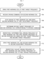
- FIG. 7 is a flowchart illustrating a method for controlling an induction heating device according to an embodiment of the present disclosure.
- FIG. 8 is a flowchart illustrating a method for obtaining final driving frequencies of a first working coil and a second working coil according to an embodiment of the present disclosure.
- the control unit 32 of the induction heating device may drive the first working coil 103 at the first target frequency (702).
- the control unit 32 may receive a driving command for the second working coil 104 while the first working coil 103 is being driven at the first target frequency (704).
- control unit 32 may stop driving of the first working coil 103 and drive the second working coil 104 at the first adjustment frequency so as to determine the second target frequency, which is the target frequency of the second working coil 104 (706).
- driving of the first working coil 103 may be completely stopped, thereby preventing an interference noise that may occur due to a difference between the driving frequencies of the first working coil 103 and the second working coil 104.
- control unit 32 may determine the second target frequency of the second working coil 104 corresponding to the driving command for the second working coil 104 (708).
- control unit 32 may determine the final driving frequency of the first working coil 103 and the final driving frequency of the second working coil 104 based on the first target frequency and the second target frequency (710).
- control unit 32 may calculate a difference value M between the first target frequency and the second target frequency (802).
- the control unit 32 may compare the calculated difference value with the preset first reference value and the preset second reference value, and may determine the driving mode of the induction heating device according to a comparison result.
- control unit 32 may determine the driving mode as the coupling mode (804), and may set the final driving frequency of the first working coil 103 and the final driving frequency of the second working coil 104 to be equal to each other (806).
- control unit 32 may determine the driving mode as a separation mode (808), and may set the final driving frequencies of respective working coils such that a difference between the final driving frequency of the first working coil 103 and the final driving frequency of the second working coil 104 corresponds to the preset noise avoidance setting value k (810).
- control unit 32 may determine the driving mode as the normal mode (812), and may set the final driving frequency of the first working coil 103 and the final driving frequency of the second working coil 104 as the first target frequency and second target frequency, respectively (814).
- the control unit 32 may drive the first working coil 103 and the second working coil 104 simultaneously at the second adjustment frequency (712).
- the process of restarting driving of the first working coil 103 which has been stopped by the above-described soft start operation, an interference noise that may occur due to a difference between the driving frequencies of the first working coil 103 and the second working coil 104 may be prevented.
- the control unit 32 may adjust the driving frequency of the first working coil 103 and the driving frequency of the second working coil 104 to the preset final driving frequencies, respectively (714).
- the driving frequencies are respectively adjusted to the final driving frequencies
- the first working coil 103 and the second working coil 104 may be respectively driven at the final driving frequencies, and thereby a heating operation may be performed on a container without generating an interference noise.
- a soft start operation to simultaneously drive the first working coil and the second working coil may be performed after the target frequency of the second working coil 104 and the final driving frequencies of respective working coils are determined. Such a soft start operation may prevent an interference noise that may occur when the two working coils are driven simultaneously.
Landscapes
- Physics & Mathematics (AREA)
- Electromagnetism (AREA)
- General Induction Heating (AREA)
- Induction Heating Cooking Devices (AREA)
- Control Of High-Frequency Heating Circuits (AREA)
Claims (15)
- Verfahren zum Steuern einer Induktionsheizvorrichtung, wobei das Verfahren umfasst:Bestimmen einer ersten Sollfrequenz einer ersten Arbeitsspule (103) gemäß einem Ansteuerbefehl für die erste Arbeitsspule (103);Bestimmen einer zweiten Sollfrequenz einer zweiten Arbeitsspule (104) gemäß einem Ansteuerbefehl für die zweite Arbeitsspule (104);Bestimmen einer endgültigen Ansteuerfrequenz der ersten Arbeitsspule (103) und einer endgültigen Ansteuerfrequenz der zweiten Arbeitsspule (104) auf der Basis der ersten Sollfrequenz bzw. der zweiten Sollfrequenz;gleichzeitiges Ansteuern der ersten Arbeitsspule (103) und der zweiten Arbeitsspule (104) mit einer voreingestellten zweiten Anpassungsfrequenz;jeweils Anpassen einer Ansteuerfrequenz der ersten Arbeitsspule (103) an die endgültige Ansteuerfrequenz der ersten Arbeitsspule (103) und Anpassen einer Ansteuerfrequenz der zweiten Arbeitsspule (104) an die endgültige Ansteuerfrequenz der zweiten Arbeitsspule (104).
- Verfahren nach Anspruch 1, das ferner umfasst: dann, wenn der Ansteuerbefehl für die zweite Arbeitsspule (104) empfangen wird, während die erste Arbeitsspule (103) mit der ersten Sollfrequenz angesteuert wird, Stoppen des Ansteuerns der ersten Arbeitsspule und Ansteuern der zweiten Arbeitsspule (104) mit einer voreingestellten ersten Anpassungsfrequenz.
- Verfahren nach Anspruch 1, wobei das Bestimmen der endgültigen Ansteuerfrequenz der ersten Arbeitsspule (103) und der endgültigen Ansteuerfrequenz der zweiten Arbeitsspule (104) basierend auf der ersten Sollfrequenz und der zweiten Sollfrequenz umfasst:Berechnen eines Differenzwerts (M) zwischen der ersten Sollfrequenz und der zweiten Sollfrequenz; undBestimmen der endgültigen Ansteuerfrequenz der ersten Arbeitsspule (103) und der endgültigen Ansteuerfrequenz der zweiten Arbeitsspule (104) gemäß einem Vergleichsergebnis zwischen dem Differenzwert (M) und einem voreingestellten Referenzwert.
- Verfahren nach Anspruch 3, wobei dann, wenn der Differenzwert (M) kleiner als ein erster Referenzwert ist, die endgültige Ansteuerfrequenz der ersten Arbeitsspule (103) und die endgültige Ansteuerfrequenz der zweiten Arbeitsspule (104) so festgelegt werden, dass sie einander gleich sind; und/oder
dann, wenn der Differenzwert (M) kleiner als ein erster Referenzwert ist, die endgültige Ansteuerfrequenz der ersten Arbeitsspule (103) und die endgültige Ansteuerfrequenz der zweiten Arbeitsspule (104) auf eine der ersten Sollfrequenz und der zweiten Sollfrequenz festgelegt werden. - Verfahren nach Anspruch 3, wobei dann, wenn der Differenzwert (M) größer oder gleich einem ersten Referenzwert und kleiner als ein zweiter Referenzwert ist, eine Differenz zwischen der endgültigen Ansteuerfrequenz der ersten Arbeitsspule (103) und der endgültigen Ansteuerfrequenz der zweiten Arbeitsspule (104) so festgelegt wird, dass sie einem voreingestellten Rauschvermeidungs-Einstellungswert (k) entspricht.
- Verfahren nach Anspruch 3, wobei dann, wenn der Differenzwert (M) größer oder gleich einem ersten Referenzwert und kleiner als ein zweiter Referenzwert ist, ein Wert, der durch Erhöhen eines größeren Werts unter der ersten Sollfrequenz und der zweiten Sollfrequenz um einen voreingestellten Rauschvermeidungs-Einstellungswert (k) erhalten wird, und ein kleinerer Wert unter der ersten Sollfrequenz und der zweiten Sollfrequenz als die endgültige Ansteuerfrequenz der ersten Arbeitsspule (103) bzw. die endgültige Ansteuerfrequenz der zweiten Arbeitsspule (104) festgelegt werden.
- Verfahren nach Anspruch 3, wobei dann, wenn der Differenzwert (M) größer oder gleich einem zweiten Referenzwert ist, die endgültige Ansteuerfrequenz der ersten Arbeitsspule (103) als die erste Sollfrequenz festgelegt wird und die endgültige Ansteuerfrequenz der zweiten Arbeitsspule (104) als die zweite Sollfrequenz festgelegt wird.
- Induktionsheizvorrichtung, die umfasst:eine erste Arbeitsspule (103), die so angeordnet ist, dass sie einem ersten Heizbereich entspricht;eine zweite Arbeitsspule (104), die so angeordnet ist, dass sie einem zweiten Heizbereich entspricht; undeine Steuereinheit, die dazu ausgelegt ist, Ansteuerfrequenzen der ersten Arbeitsspule (103) und der zweiten Arbeitsspule (104) gemäß einem von einem Anwender eingegebenen Ansteuerbefehl anzupassen,wobei die Steuereinheit zu Folgendem ausgelegt ist:Bestimmen einer ersten Sollfrequenz einer ersten Arbeitsspule (103) gemäß einem Ansteuerbefehl für die erste Arbeitsspule (103);Bestimmen einer zweiten Sollfrequenz einer zweiten Arbeitsspule (104) gemäß einem Ansteuerbefehl für die zweite Arbeitsspule (104);Bestimmen einer endgültigen Ansteuerfrequenz der ersten Arbeitsspule (103) und einer endgültigen Ansteuerfrequenz der zweiten Arbeitsspule (104) basierend auf der ersten Sollfrequenz bzw. der zweiten Sollfrequenz;gleichzeitiges Ansteuern der ersten Arbeitsspule (103) und der zweiten Arbeitsspule (104) mit einer zweiten Anpassungsfrequenz; undjeweils Anpassen einer Ansteuerfrequenz der ersten Arbeitsspule (103) an die endgültige Ansteuerfrequenz der ersten Arbeitsspule (103) und Anpassen einer Ansteuerfrequenz der zweiten Arbeitsspule (104) an die endgültige Ansteuerfrequenz der zweiten Arbeitsspule (104).
- Vorrichtung nach Anspruch 8, wobei die Steuereinheit zu Folgendem ausgelegt ist:
dann, wenn der Ansteuerbefehl für die zweite Arbeitsspule (104) empfangen wird, während die erste Arbeitsspule (103) mit der ersten Sollfrequenz angesteuert wird, Stoppen des Ansteuerns der ersten Arbeitsspule und Ansteuern der zweiten Arbeitsspule (104) mit einer voreingestellten ersten Anpassungsfrequenz. - Induktionsheizvorrichtung nach Anspruch 8, wobei die Steuereinheit zu Folgendem ausgelegt ist:Berechnen eines Differenzwerts (M) zwischen der ersten Sollfrequenz und der zweiten Sollfrequenz; undBestimmen der endgültigen Ansteuerfrequenz der ersten Arbeitsspule (103) und der endgültigen Ansteuerfrequenz der zweiten Arbeitsspule (104) gemäß einem Vergleichsergebnis zwischen dem Differenzwert (M) und einem voreingestellten Referenzwert.
- Induktionsheizvorrichtung nach Anspruch 10, wobei dann, wenn der Differenzwert (M) kleiner als ein erster Referenzwert ist, die endgültige Ansteuerfrequenz der ersten Arbeitsspule (103) und die endgültige Ansteuerfrequenz der zweiten Arbeitsspule (104) so festgelegt werden, dass sie einander gleich sind.
- Vorrichtung nach Anspruch 10, wobei dann, wenn der Differenzwert (M) kleiner als ein erster Referenzwert ist, die endgültige Ansteuerfrequenz der ersten Arbeitsspule (103) und die endgültige Ansteuerfrequenz der zweiten Arbeitsspule (104) auf eine der ersten Sollfrequenz und der zweiten Sollfrequenz festgelegt werden.
- Vorrichtung nach Anspruch 10, wobei dann, wenn der Differenzwert (M) größer oder gleich einem ersten Referenzwert und kleiner als ein zweiter Referenzwert ist, eine Differenz zwischen der endgültigen Ansteuerfrequenz der ersten Arbeitsspule (103) und der endgültigen Ansteuerfrequenz der zweiten Arbeitsspule (104) so festgelegt wird, dass sie einem voreingestellten Rauschvermeidungs-Einstellungswert (k) entspricht.
- Vorrichtung nach Anspruch 10, wobei dann, wenn der Differenzwert (M) größer oder gleich einem ersten Referenzwert und kleiner als ein zweiter Referenzwert ist, ein Wert, der durch Erhöhen eines größeren Werts unter der ersten Sollfrequenz und der zweiten Sollfrequenz um einen voreingestellten Rauschvermeidungs-Einstellungswert (k) erhalten wird, und ein kleinerer Wert unter der ersten Sollfrequenz und der zweiten Sollfrequenz als die endgültige Ansteuerfrequenz der ersten Arbeitsspule (103) bzw. die endgültige Ansteuerfrequenz der zweiten Arbeitsspule (104) festgelegt werden.
- Vorrichtung nach Anspruch 10, wobei dann, wenn der Differenzwert (M) größer oder gleich einem zweiten Referenzwert ist, die endgültige Ansteuerfrequenz der ersten Arbeitsspule (103) als die erste Sollfrequenz festgelegt wird und die endgültige Ansteuerfrequenz der zweiten Arbeitsspule (104) als die zweite Sollfrequenz festgelegt wird.
Applications Claiming Priority (2)
| Application Number | Priority Date | Filing Date | Title |
|---|---|---|---|
| KR1020180103042A KR102607284B1 (ko) | 2018-08-30 | 2018-08-30 | 유도 가열 장치 및 유도 가열 장치의 제어 방법 |
| PCT/KR2019/011205 WO2020046068A1 (ko) | 2018-08-30 | 2019-08-30 | 유도 가열 장치 및 유도 가열 장치의 제어 방법 |
Publications (3)
| Publication Number | Publication Date |
|---|---|
| EP3846587A1 EP3846587A1 (de) | 2021-07-07 |
| EP3846587A4 EP3846587A4 (de) | 2022-06-22 |
| EP3846587B1 true EP3846587B1 (de) | 2023-10-11 |
Family
ID=67810441
Family Applications (2)
| Application Number | Title | Priority Date | Filing Date |
|---|---|---|---|
| EP19194559.1A Active EP3618568B1 (de) | 2018-08-30 | 2019-08-30 | Induktionsheizvorrichtung und verfahren zur steuerung einer induktionsheizvorrichtung |
| EP19855331.5A Active EP3846587B1 (de) | 2018-08-30 | 2019-08-30 | Induktionsheizvorrichtung und steuerverfahren für eine induktionsheizvorrichtung |
Family Applications Before (1)
| Application Number | Title | Priority Date | Filing Date |
|---|---|---|---|
| EP19194559.1A Active EP3618568B1 (de) | 2018-08-30 | 2019-08-30 | Induktionsheizvorrichtung und verfahren zur steuerung einer induktionsheizvorrichtung |
Country Status (6)
| Country | Link |
|---|---|
| US (2) | US12177953B2 (de) |
| EP (2) | EP3618568B1 (de) |
| KR (1) | KR102607284B1 (de) |
| CN (1) | CN112640575B (de) |
| AU (1) | AU2019328101B2 (de) |
| WO (2) | WO2020046068A1 (de) |
Families Citing this family (9)
| Publication number | Priority date | Publication date | Assignee | Title |
|---|---|---|---|---|
| KR102607284B1 (ko) | 2018-08-30 | 2023-11-27 | 엘지전자 주식회사 | 유도 가열 장치 및 유도 가열 장치의 제어 방법 |
| WO2020046070A1 (ko) * | 2018-08-30 | 2020-03-05 | 엘지전자 주식회사 | 유도 가열 장치 및 유도 가열 장치의 제어 방법 |
| KR102680589B1 (ko) * | 2019-10-23 | 2024-07-03 | 삼성전자주식회사 | 조리 기기 및 그 구동 방법 |
| KR102903153B1 (ko) * | 2020-05-06 | 2025-12-23 | 엘지전자 주식회사 | 유도 가열 장치 및 유도 가열 장치의 제어 방법 |
| KR102901499B1 (ko) * | 2020-05-06 | 2025-12-17 | 엘지전자 주식회사 | 유도 가열 장치 및 유도 가열 장치의 제어 방법 |
| CN114364072A (zh) * | 2020-10-14 | 2022-04-15 | 杭州九阳小家电有限公司 | 低噪音电磁加热装置及其控制方法 |
| CN114698166B (zh) * | 2020-12-29 | 2023-06-16 | 佛山市顺德区美的电热电器制造有限公司 | 电磁加热设备及噪音抑制方法、加热控制系统、存储介质 |
| KR102817459B1 (ko) * | 2021-01-07 | 2025-06-05 | 엘지전자 주식회사 | 유도 가열 장치 및 유도 가열 장치의 제어 방법 |
| KR20220115366A (ko) * | 2021-02-10 | 2022-08-17 | 엘지전자 주식회사 | 유도 가열 장치 및 유도 가열 장치의 제어 방법 |
Family Cites Families (17)
| Publication number | Priority date | Publication date | Assignee | Title |
|---|---|---|---|---|
| ES2201937B1 (es) * | 2003-11-03 | 2005-02-01 | Bsh Electrodomesticos España, S.A. | Procedimiento para el funcionamiento de un circuito convertidor. |
| TWI394547B (zh) * | 2009-03-18 | 2013-05-01 | Delta Electronics Inc | 加熱裝置 |
| EP3270661A1 (de) | 2011-03-28 | 2018-01-17 | Samsung Electronics Co., Ltd. | Steuerungsverfahren eines induktionsherds |
| KR20120109965A (ko) | 2011-03-28 | 2012-10-09 | 삼성전자주식회사 | 유도가열조리기의 제어방법 |
| KR101844404B1 (ko) * | 2011-03-28 | 2018-04-03 | 삼성전자주식회사 | 유도가열조리기 |
| ES2632582T3 (es) * | 2011-03-28 | 2017-09-14 | BSH Hausgeräte GmbH | Dispositivo de aparato de cocción |
| JP5323148B2 (ja) * | 2011-08-10 | 2013-10-23 | 三菱電機株式会社 | 誘導加熱調理器 |
| JP5398862B2 (ja) * | 2012-03-15 | 2014-01-29 | 三菱電機株式会社 | 誘導加熱調理器 |
| US10455647B2 (en) * | 2014-11-26 | 2019-10-22 | Samsung Electronics Co., Ltd. | Cooking apparatus and method for controlling the same |
| KR101735754B1 (ko) * | 2015-09-08 | 2017-05-15 | 자원전자 주식회사 | 고주파 인버터 유도코일 구동회로 |
| KR102382949B1 (ko) * | 2015-12-23 | 2022-04-06 | 쿠쿠전자 주식회사 | 유도 가열 조리기 |
| JP2017168236A (ja) * | 2016-03-15 | 2017-09-21 | 日立アプライアンス株式会社 | 誘導加熱調理器 |
| CN106247416B (zh) | 2016-08-10 | 2018-10-23 | 深圳拓邦股份有限公司 | 多灶头电磁炉及其功率控制方法 |
| JP6830347B2 (ja) | 2016-12-09 | 2021-02-17 | 太陽誘電株式会社 | コイル部品 |
| JP6921232B2 (ja) * | 2017-12-07 | 2021-08-18 | 三菱電機株式会社 | 誘導加熱調理器 |
| CN111742613B (zh) * | 2018-02-23 | 2022-06-28 | 三菱电机株式会社 | 感应加热烹调器 |
| KR102607284B1 (ko) | 2018-08-30 | 2023-11-27 | 엘지전자 주식회사 | 유도 가열 장치 및 유도 가열 장치의 제어 방법 |
-
2018
- 2018-08-30 KR KR1020180103042A patent/KR102607284B1/ko active Active
-
2019
- 2019-08-30 EP EP19194559.1A patent/EP3618568B1/de active Active
- 2019-08-30 US US17/271,159 patent/US12177953B2/en active Active
- 2019-08-30 WO PCT/KR2019/011205 patent/WO2020046068A1/ko not_active Ceased
- 2019-08-30 CN CN201980056698.XA patent/CN112640575B/zh active Active
- 2019-08-30 AU AU2019328101A patent/AU2019328101B2/en active Active
- 2019-08-30 WO PCT/KR2019/011202 patent/WO2020046067A1/ko not_active Ceased
- 2019-08-30 EP EP19855331.5A patent/EP3846587B1/de active Active
- 2019-08-30 US US16/556,504 patent/US11540360B2/en active Active
Also Published As
| Publication number | Publication date |
|---|---|
| US12177953B2 (en) | 2024-12-24 |
| US11540360B2 (en) | 2022-12-27 |
| CN112640575A (zh) | 2021-04-09 |
| KR20200025546A (ko) | 2020-03-10 |
| WO2020046067A1 (ko) | 2020-03-05 |
| WO2020046068A1 (ko) | 2020-03-05 |
| EP3846587A1 (de) | 2021-07-07 |
| US20200077471A1 (en) | 2020-03-05 |
| US20210337636A1 (en) | 2021-10-28 |
| AU2019328101A1 (en) | 2021-04-15 |
| KR102607284B1 (ko) | 2023-11-27 |
| EP3618568B1 (de) | 2023-06-28 |
| EP3618568A1 (de) | 2020-03-04 |
| AU2019328101B2 (en) | 2023-01-12 |
| EP3846587A4 (de) | 2022-06-22 |
| CN112640575B (zh) | 2023-08-08 |
Similar Documents
| Publication | Publication Date | Title |
|---|---|---|
| EP3846587B1 (de) | Induktionsheizvorrichtung und steuerverfahren für eine induktionsheizvorrichtung | |
| US10004114B2 (en) | Induction heating cooker | |
| KR102796753B1 (ko) | 유도 가열 장치 및 유도 가열 장치의 제어 방법 | |
| KR20190051726A (ko) | 유도 가열 장치 및 유도 가열 장치의 용기 판별 방법 | |
| US10719165B2 (en) | Touch sensing apparatus based on ultrasonic waves, cooking apparatus and home appliance including the same | |
| KR20210120660A (ko) | 유도 가열 장치 및 유도 가열 장치의 제어 방법 | |
| EP3846586B1 (de) | Induktionsheizvorrichtung und verfahren zur steuerung einer induktionsheizvorrichtung | |
| KR102127266B1 (ko) | 유도 가열 장치 및 유도 가열 장치의 제어 방법 | |
| KR20090005142U (ko) | 유도가열 조리기 | |
| KR102877686B1 (ko) | 유도 가열 장치 및 유도 가열 장치의 제어 방법 | |
| KR20190131386A (ko) | 제어 알고리즘 및 회로 구조가 개선된 유도 가열 장치 | |
| US12232241B2 (en) | Induction heating device and method for controlling induction heating device | |
| US12342444B2 (en) | Induction heating apparatus and method for controlling the same | |
| KR102165578B1 (ko) | 가열 장치 및 이의 제어 방법 | |
| KR102153499B1 (ko) | 가열 장치 및 이의 출력 제어 방법 | |
| KR20210027996A (ko) | 고주파수 구동이 가능한 유도 가열 장치 | |
| KR102175639B1 (ko) | 가열 장치 및 이의 출력 제어 방법 | |
| JP2011249198A (ja) | 誘導加熱調理器 | |
| EP4135479A1 (de) | Induktionskochfeld | |
| KR20220114906A (ko) | 유도 가열 장치 및 유도 가열 장치의 제어 방법 |
Legal Events
| Date | Code | Title | Description |
|---|---|---|---|
| STAA | Information on the status of an ep patent application or granted ep patent |
Free format text: STATUS: THE INTERNATIONAL PUBLICATION HAS BEEN MADE |
|
| STAA | Information on the status of an ep patent application or granted ep patent |
Free format text: STATUS: REQUEST FOR EXAMINATION WAS MADE |
|
| PUAI | Public reference made under article 153(3) epc to a published international application that has entered the european phase |
Free format text: ORIGINAL CODE: 0009012 |
|
| 17P | Request for examination filed |
Effective date: 20210324 |
|
| AK | Designated contracting states |
Kind code of ref document: A1 Designated state(s): AL AT BE BG CH CY CZ DE DK EE ES FI FR GB GR HR HU IE IS IT LI LT LU LV MC MK MT NL NO PL PT RO RS SE SI SK SM TR |
|
| DAV | Request for validation of the european patent (deleted) | ||
| DAX | Request for extension of the european patent (deleted) | ||
| A4 | Supplementary search report drawn up and despatched |
Effective date: 20220525 |
|
| RIC1 | Information provided on ipc code assigned before grant |
Ipc: H05B 6/06 20060101AFI20220519BHEP |
|
| GRAP | Despatch of communication of intention to grant a patent |
Free format text: ORIGINAL CODE: EPIDOSNIGR1 |
|
| STAA | Information on the status of an ep patent application or granted ep patent |
Free format text: STATUS: GRANT OF PATENT IS INTENDED |
|
| INTG | Intention to grant announced |
Effective date: 20230503 |
|
| GRAS | Grant fee paid |
Free format text: ORIGINAL CODE: EPIDOSNIGR3 |
|
| GRAA | (expected) grant |
Free format text: ORIGINAL CODE: 0009210 |
|
| STAA | Information on the status of an ep patent application or granted ep patent |
Free format text: STATUS: THE PATENT HAS BEEN GRANTED |
|
| AK | Designated contracting states |
Kind code of ref document: B1 Designated state(s): AL AT BE BG CH CY CZ DE DK EE ES FI FR GB GR HR HU IE IS IT LI LT LU LV MC MK MT NL NO PL PT RO RS SE SI SK SM TR |
|
| REG | Reference to a national code |
Ref country code: GB Ref legal event code: FG4D |
|
| REG | Reference to a national code |
Ref country code: CH Ref legal event code: EP |
|
| REG | Reference to a national code |
Ref country code: IE Ref legal event code: FG4D |
|
| REG | Reference to a national code |
Ref country code: DE Ref legal event code: R096 Ref document number: 602019039335 Country of ref document: DE |
|
| REG | Reference to a national code |
Ref country code: LT Ref legal event code: MG9D |
|
| REG | Reference to a national code |
Ref country code: NL Ref legal event code: MP Effective date: 20231011 |
|
| REG | Reference to a national code |
Ref country code: AT Ref legal event code: MK05 Ref document number: 1621530 Country of ref document: AT Kind code of ref document: T Effective date: 20231011 |
|
| PG25 | Lapsed in a contracting state [announced via postgrant information from national office to epo] |
Ref country code: NL Free format text: LAPSE BECAUSE OF FAILURE TO SUBMIT A TRANSLATION OF THE DESCRIPTION OR TO PAY THE FEE WITHIN THE PRESCRIBED TIME-LIMIT Effective date: 20231011 |
|
| PG25 | Lapsed in a contracting state [announced via postgrant information from national office to epo] |
Ref country code: GR Free format text: LAPSE BECAUSE OF FAILURE TO SUBMIT A TRANSLATION OF THE DESCRIPTION OR TO PAY THE FEE WITHIN THE PRESCRIBED TIME-LIMIT Effective date: 20240112 |
|
| PG25 | Lapsed in a contracting state [announced via postgrant information from national office to epo] |
Ref country code: IS Free format text: LAPSE BECAUSE OF FAILURE TO SUBMIT A TRANSLATION OF THE DESCRIPTION OR TO PAY THE FEE WITHIN THE PRESCRIBED TIME-LIMIT Effective date: 20240211 |
|
| PG25 | Lapsed in a contracting state [announced via postgrant information from national office to epo] |
Ref country code: LT Free format text: LAPSE BECAUSE OF FAILURE TO SUBMIT A TRANSLATION OF THE DESCRIPTION OR TO PAY THE FEE WITHIN THE PRESCRIBED TIME-LIMIT Effective date: 20231011 |
|
| PG25 | Lapsed in a contracting state [announced via postgrant information from national office to epo] |
Ref country code: AT Free format text: LAPSE BECAUSE OF FAILURE TO SUBMIT A TRANSLATION OF THE DESCRIPTION OR TO PAY THE FEE WITHIN THE PRESCRIBED TIME-LIMIT Effective date: 20231011 |
|
| PG25 | Lapsed in a contracting state [announced via postgrant information from national office to epo] |
Ref country code: ES Free format text: LAPSE BECAUSE OF FAILURE TO SUBMIT A TRANSLATION OF THE DESCRIPTION OR TO PAY THE FEE WITHIN THE PRESCRIBED TIME-LIMIT Effective date: 20231011 |
|
| PG25 | Lapsed in a contracting state [announced via postgrant information from national office to epo] |
Ref country code: LT Free format text: LAPSE BECAUSE OF FAILURE TO SUBMIT A TRANSLATION OF THE DESCRIPTION OR TO PAY THE FEE WITHIN THE PRESCRIBED TIME-LIMIT Effective date: 20231011 Ref country code: IS Free format text: LAPSE BECAUSE OF FAILURE TO SUBMIT A TRANSLATION OF THE DESCRIPTION OR TO PAY THE FEE WITHIN THE PRESCRIBED TIME-LIMIT Effective date: 20240211 Ref country code: GR Free format text: LAPSE BECAUSE OF FAILURE TO SUBMIT A TRANSLATION OF THE DESCRIPTION OR TO PAY THE FEE WITHIN THE PRESCRIBED TIME-LIMIT Effective date: 20240112 Ref country code: ES Free format text: LAPSE BECAUSE OF FAILURE TO SUBMIT A TRANSLATION OF THE DESCRIPTION OR TO PAY THE FEE WITHIN THE PRESCRIBED TIME-LIMIT Effective date: 20231011 Ref country code: BG Free format text: LAPSE BECAUSE OF FAILURE TO SUBMIT A TRANSLATION OF THE DESCRIPTION OR TO PAY THE FEE WITHIN THE PRESCRIBED TIME-LIMIT Effective date: 20240111 Ref country code: AT Free format text: LAPSE BECAUSE OF FAILURE TO SUBMIT A TRANSLATION OF THE DESCRIPTION OR TO PAY THE FEE WITHIN THE PRESCRIBED TIME-LIMIT Effective date: 20231011 Ref country code: PT Free format text: LAPSE BECAUSE OF FAILURE TO SUBMIT A TRANSLATION OF THE DESCRIPTION OR TO PAY THE FEE WITHIN THE PRESCRIBED TIME-LIMIT Effective date: 20240212 |
|
| PG25 | Lapsed in a contracting state [announced via postgrant information from national office to epo] |
Ref country code: SE Free format text: LAPSE BECAUSE OF FAILURE TO SUBMIT A TRANSLATION OF THE DESCRIPTION OR TO PAY THE FEE WITHIN THE PRESCRIBED TIME-LIMIT Effective date: 20231011 Ref country code: RS Free format text: LAPSE BECAUSE OF FAILURE TO SUBMIT A TRANSLATION OF THE DESCRIPTION OR TO PAY THE FEE WITHIN THE PRESCRIBED TIME-LIMIT Effective date: 20231011 Ref country code: PL Free format text: LAPSE BECAUSE OF FAILURE TO SUBMIT A TRANSLATION OF THE DESCRIPTION OR TO PAY THE FEE WITHIN THE PRESCRIBED TIME-LIMIT Effective date: 20231011 Ref country code: NO Free format text: LAPSE BECAUSE OF FAILURE TO SUBMIT A TRANSLATION OF THE DESCRIPTION OR TO PAY THE FEE WITHIN THE PRESCRIBED TIME-LIMIT Effective date: 20240111 Ref country code: LV Free format text: LAPSE BECAUSE OF FAILURE TO SUBMIT A TRANSLATION OF THE DESCRIPTION OR TO PAY THE FEE WITHIN THE PRESCRIBED TIME-LIMIT Effective date: 20231011 Ref country code: HR Free format text: LAPSE BECAUSE OF FAILURE TO SUBMIT A TRANSLATION OF THE DESCRIPTION OR TO PAY THE FEE WITHIN THE PRESCRIBED TIME-LIMIT Effective date: 20231011 |
|
| PG25 | Lapsed in a contracting state [announced via postgrant information from national office to epo] |
Ref country code: DK Free format text: LAPSE BECAUSE OF FAILURE TO SUBMIT A TRANSLATION OF THE DESCRIPTION OR TO PAY THE FEE WITHIN THE PRESCRIBED TIME-LIMIT Effective date: 20231011 |
|
| REG | Reference to a national code |
Ref country code: DE Ref legal event code: R097 Ref document number: 602019039335 Country of ref document: DE |
|
| PG25 | Lapsed in a contracting state [announced via postgrant information from national office to epo] |
Ref country code: CZ Free format text: LAPSE BECAUSE OF FAILURE TO SUBMIT A TRANSLATION OF THE DESCRIPTION OR TO PAY THE FEE WITHIN THE PRESCRIBED TIME-LIMIT Effective date: 20231011 |
|
| PG25 | Lapsed in a contracting state [announced via postgrant information from national office to epo] |
Ref country code: SK Free format text: LAPSE BECAUSE OF FAILURE TO SUBMIT A TRANSLATION OF THE DESCRIPTION OR TO PAY THE FEE WITHIN THE PRESCRIBED TIME-LIMIT Effective date: 20231011 |
|
| PG25 | Lapsed in a contracting state [announced via postgrant information from national office to epo] |
Ref country code: SM Free format text: LAPSE BECAUSE OF FAILURE TO SUBMIT A TRANSLATION OF THE DESCRIPTION OR TO PAY THE FEE WITHIN THE PRESCRIBED TIME-LIMIT Effective date: 20231011 Ref country code: SK Free format text: LAPSE BECAUSE OF FAILURE TO SUBMIT A TRANSLATION OF THE DESCRIPTION OR TO PAY THE FEE WITHIN THE PRESCRIBED TIME-LIMIT Effective date: 20231011 Ref country code: RO Free format text: LAPSE BECAUSE OF FAILURE TO SUBMIT A TRANSLATION OF THE DESCRIPTION OR TO PAY THE FEE WITHIN THE PRESCRIBED TIME-LIMIT Effective date: 20231011 Ref country code: EE Free format text: LAPSE BECAUSE OF FAILURE TO SUBMIT A TRANSLATION OF THE DESCRIPTION OR TO PAY THE FEE WITHIN THE PRESCRIBED TIME-LIMIT Effective date: 20231011 Ref country code: DK Free format text: LAPSE BECAUSE OF FAILURE TO SUBMIT A TRANSLATION OF THE DESCRIPTION OR TO PAY THE FEE WITHIN THE PRESCRIBED TIME-LIMIT Effective date: 20231011 Ref country code: CZ Free format text: LAPSE BECAUSE OF FAILURE TO SUBMIT A TRANSLATION OF THE DESCRIPTION OR TO PAY THE FEE WITHIN THE PRESCRIBED TIME-LIMIT Effective date: 20231011 |
|
| PLBE | No opposition filed within time limit |
Free format text: ORIGINAL CODE: 0009261 |
|
| STAA | Information on the status of an ep patent application or granted ep patent |
Free format text: STATUS: NO OPPOSITION FILED WITHIN TIME LIMIT |
|
| 26N | No opposition filed |
Effective date: 20240712 |
|
| PG25 | Lapsed in a contracting state [announced via postgrant information from national office to epo] |
Ref country code: SI Free format text: LAPSE BECAUSE OF FAILURE TO SUBMIT A TRANSLATION OF THE DESCRIPTION OR TO PAY THE FEE WITHIN THE PRESCRIBED TIME-LIMIT Effective date: 20231011 |
|
| PG25 | Lapsed in a contracting state [announced via postgrant information from national office to epo] |
Ref country code: SI Free format text: LAPSE BECAUSE OF FAILURE TO SUBMIT A TRANSLATION OF THE DESCRIPTION OR TO PAY THE FEE WITHIN THE PRESCRIBED TIME-LIMIT Effective date: 20231011 |
|
| REG | Reference to a national code |
Ref country code: CH Ref legal event code: PL |
|
| PG25 | Lapsed in a contracting state [announced via postgrant information from national office to epo] |
Ref country code: LU Free format text: LAPSE BECAUSE OF NON-PAYMENT OF DUE FEES Effective date: 20240830 |
|
| PG25 | Lapsed in a contracting state [announced via postgrant information from national office to epo] |
Ref country code: CH Free format text: LAPSE BECAUSE OF NON-PAYMENT OF DUE FEES Effective date: 20240831 Ref country code: MC Free format text: LAPSE BECAUSE OF FAILURE TO SUBMIT A TRANSLATION OF THE DESCRIPTION OR TO PAY THE FEE WITHIN THE PRESCRIBED TIME-LIMIT Effective date: 20231011 |
|
| REG | Reference to a national code |
Ref country code: BE Ref legal event code: MM Effective date: 20240831 |
|
| PG25 | Lapsed in a contracting state [announced via postgrant information from national office to epo] |
Ref country code: BE Free format text: LAPSE BECAUSE OF NON-PAYMENT OF DUE FEES Effective date: 20240831 |
|
| PG25 | Lapsed in a contracting state [announced via postgrant information from national office to epo] |
Ref country code: IE Free format text: LAPSE BECAUSE OF NON-PAYMENT OF DUE FEES Effective date: 20240830 |
|
| PG25 | Lapsed in a contracting state [announced via postgrant information from national office to epo] |
Ref country code: FI Free format text: LAPSE BECAUSE OF FAILURE TO SUBMIT A TRANSLATION OF THE DESCRIPTION OR TO PAY THE FEE WITHIN THE PRESCRIBED TIME-LIMIT Effective date: 20231011 |
|
| PGFP | Annual fee paid to national office [announced via postgrant information from national office to epo] |
Ref country code: DE Payment date: 20250707 Year of fee payment: 7 |
|
| PGFP | Annual fee paid to national office [announced via postgrant information from national office to epo] |
Ref country code: IT Payment date: 20250710 Year of fee payment: 7 |
|
| PGFP | Annual fee paid to national office [announced via postgrant information from national office to epo] |
Ref country code: GB Payment date: 20250707 Year of fee payment: 7 |
|
| PGFP | Annual fee paid to national office [announced via postgrant information from national office to epo] |
Ref country code: FR Payment date: 20250715 Year of fee payment: 7 |
|
| PG25 | Lapsed in a contracting state [announced via postgrant information from national office to epo] |
Ref country code: CY Free format text: LAPSE BECAUSE OF FAILURE TO SUBMIT A TRANSLATION OF THE DESCRIPTION OR TO PAY THE FEE WITHIN THE PRESCRIBED TIME-LIMIT; INVALID AB INITIO Effective date: 20190830 |
|
| PG25 | Lapsed in a contracting state [announced via postgrant information from national office to epo] |
Ref country code: HU Free format text: LAPSE BECAUSE OF FAILURE TO SUBMIT A TRANSLATION OF THE DESCRIPTION OR TO PAY THE FEE WITHIN THE PRESCRIBED TIME-LIMIT; INVALID AB INITIO Effective date: 20190830 |