EP3846589B1 - Kochfeld, das induktoren mit ovalem umriss umfasst - Google Patents
Kochfeld, das induktoren mit ovalem umriss umfasst Download PDFInfo
- Publication number
- EP3846589B1 EP3846589B1 EP20217025.4A EP20217025A EP3846589B1 EP 3846589 B1 EP3846589 B1 EP 3846589B1 EP 20217025 A EP20217025 A EP 20217025A EP 3846589 B1 EP3846589 B1 EP 3846589B1
- Authority
- EP
- European Patent Office
- Prior art keywords
- inductors
- inductor
- adjacent
- subset
- hob
- Prior art date
- Legal status (The legal status is an assumption and is not a legal conclusion. Google has not performed a legal analysis and makes no representation as to the accuracy of the status listed.)
- Active
Links
Images


Classifications
-
- H—ELECTRICITY
- H05—ELECTRIC TECHNIQUES NOT OTHERWISE PROVIDED FOR
- H05B—ELECTRIC HEATING; ELECTRIC LIGHT SOURCES NOT OTHERWISE PROVIDED FOR; CIRCUIT ARRANGEMENTS FOR ELECTRIC LIGHT SOURCES, IN GENERAL
- H05B6/00—Heating by electric, magnetic or electromagnetic fields
- H05B6/02—Induction heating
- H05B6/10—Induction heating apparatus, other than furnaces, for specific applications
- H05B6/12—Cooking devices
- H05B6/1209—Cooking devices induction cooking plates or the like and devices to be used in combination with them
-
- H—ELECTRICITY
- H05—ELECTRIC TECHNIQUES NOT OTHERWISE PROVIDED FOR
- H05B—ELECTRIC HEATING; ELECTRIC LIGHT SOURCES NOT OTHERWISE PROVIDED FOR; CIRCUIT ARRANGEMENTS FOR ELECTRIC LIGHT SOURCES, IN GENERAL
- H05B2213/00—Aspects relating both to resistive heating and to induction heating, covered by H05B3/00 and H05B6/00
- H05B2213/03—Heating plates made out of a matrix of heating elements that can define heating areas adapted to cookware randomly placed on the heating plate
-
- Y—GENERAL TAGGING OF NEW TECHNOLOGICAL DEVELOPMENTS; GENERAL TAGGING OF CROSS-SECTIONAL TECHNOLOGIES SPANNING OVER SEVERAL SECTIONS OF THE IPC; TECHNICAL SUBJECTS COVERED BY FORMER USPC CROSS-REFERENCE ART COLLECTIONS [XRACs] AND DIGESTS
- Y02—TECHNOLOGIES OR APPLICATIONS FOR MITIGATION OR ADAPTATION AGAINST CLIMATE CHANGE
- Y02B—CLIMATE CHANGE MITIGATION TECHNOLOGIES RELATED TO BUILDINGS, e.g. HOUSING, HOUSE APPLIANCES OR RELATED END-USER APPLICATIONS
- Y02B40/00—Technologies aiming at improving the efficiency of home appliances, e.g. induction cooking or efficient technologies for refrigerators, freezers or dish washers
Definitions
- the present invention relates to an induction cooktop.
- it concerns a hob having at least one part without predefined hotplates.
- induction cooktops comprise a cooking plate, most often rectangular, and several inductors distributed in a heating surface under the cooking plate.
- Each inductor is generally formed of a winding, or winding of conductive wires for example, with a substantially circular outline.
- cooking table having at least one part without predefined hotplates tables in which the heating zones in said at least one part are flexible.
- the heating zones are created as containers are placed depending on the size and position of said containers.
- These cooking tables are called matrix tables when the entire table is without predefined hotplates, and mixed tables when only part of the table is without predefined hotplates.
- the inductors can be distributed in a so-called regular two-dimensional arrangement and in which the inductors are distributed one next to the other so as to form rows and columns of inductors.
- EP 2 775 783 A2 discloses an induction cooktop comprising a rectangular cooking plate, and several identical inductors each having a center, the inductors being distributed in a two-dimensional arrangement in a heating plane extending under the cooking plate. cooking.
- the present invention aims to resolve at least one of the aforementioned drawbacks.
- the invention relates to an induction cooktop comprising a rectangular cooking plate, and several identical inductors each having a center, the inductors being distributed in a two-dimensional arrangement in a heating plane extending under the cooking plate, the centers inductors being aligned in rows and columns in a first direction and a second direction.
- each inductor is formed of a winding of conductive wires with a substantially oval contour and has a main axis of symmetry, the main axes of the inductors extending in directions parallel to each other and oblique to the first direction. and the second direction.
- the inductors having an oval outline and inclined relative to their alignment directions (first direction and second direction), this allows better optimization of the surface occupied in the heating plane. Indeed, the inductors thus constituted and arranged can more easily be embedded with each other, in the sense that at least part of an inductor can be placed between two inductors without the inductors overlapping each other. The heating surface is thus optimized.
- the regular arrangement of the inductors in the first direction and the second direction simplifies the detection of the containers and the control of the inductors.
- oval shape of the contours of the inductors due to its rounded portions, is well suited to use with containers whose bottom is circular.
- the inductors comprise first subsets of inductors whose centers are aligned in the first direction, the inductors being distributed in the heating plane so that a rectangle circumscribes any first subset of The inductors overlap a rectangle circumscribed by a first subset of adjacent inductors.
- the inductors are thus embedded with each other in the first direction. This optimization of the space occupied by the inductors in the heating plane is allowed by the inclination in the oblique direction and the oval shape of the inductors.
- the inductors comprise second subsets of inductors whose centers are aligned in the second direction, the inductors being distributed in the heating plane so that a rectangle circumscribes any second subset d The inductors overlap a rectangle circumscribed by a second adjacent subset.
- the inductors are thus further embedded with each other in the second direction. This allows even better optimization of the space occupied by the inductors in the heating plane.
- each inductor is formed of a winding of conductive wires with an elliptical contour.
- the elliptical shape or contour of the inductors allows very good integration of the inductors with each other thanks to the rounding of the contour.
- the elliptical contour by its rounding makes it possible to limit the mutual inductances between two adjacent inductors.
- each inductor is formed of a winding of conductive wires with an oblong outline.
- the oblong contour of the inductors also allows good optimization of the space occupied by the inductors in the heating plane.
- the oblong contour is formed of rectilinear portions of directions parallel to each other, said rectilinear portions being connected on either side by two semi-circular portions, any inductor having a rectilinear portion facing an adjacent inductor is arranged so that said rectilinear portion of said inductor faces a semicircular portion of said adjacent inductor.
- Such an arrangement of the inductors in the heating plane makes it possible to limit the mutual inductance which may be caused by the arrangement opposite two respective rectilinear positions of two adjacent inductors.
- the length of the rectilinear portions is less than or equal to the diameter of the semi-circular portions.
- the length of the rectilinear portions is significantly greater than the diameter of the semi-circular portions.
- Such sizing of the inductors makes it possible to limit the mutual inductance which could be generated by the arrangement opposite two respective rectilinear portions of two adjacent inductors.
- each of the first direction and second direction is orthogonal to one side of the cooking plate.
- the space occupied by the inductors in the heating plane is even more optimized.
- said cooking table includes a man-machine interface inserting into the heating surface.
- the man-machine interface can be adapted to command and control the inductors, their nominal power, etc.
- the invention relates to an induction cooktop 1 represented schematically by the figures.
- the cooking surface 1 comprises a cooking plate not shown here and heating means constituted by a set of inductors 3.
- the inductors 3 extend in a plane, called heating plane 2.
- the hob here is rectangular, which is the most common shape in the field of hobs.
- the cooking plate comprises two longitudinal sides and two lateral sides.
- rectangular cooking plate we mean any plate whose sides form a quadrilateral with right angles.
- the cooking plate can be square for example.
- Heating surface 2 extends below the cooking plate.
- the heating surface 2 can be rectangular, in correspondence with the cooking plate located above.
- the heating plane 2 can also have another polygonal shape, for example in order to integrate a Human-Machine Interface (HMI) or other elements not having a heating function.
- HMI Human-Machine Interface
- the longitudinal sides of the cooking plate correspond respectively to a front edge and a rear edge of said cooking plate in the use position.
- front edge we mean the side of the cooking plate closest to a user facing it for use, and by rear edge the side of the cooking plate furthest away from said user.
- the longitudinal sides of the cooking plate extend in a longitudinal direction and the lateral sides of the cooking plate extend in a transverse direction.
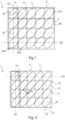
- THE figures 1, 2 , 3a, 3b , 4 represent embodiments in which the hob 1 is a matrix hob, that is to say a hob having no predefined hotplates.
- predefined heating zones we mean zones previously used (for use of the hob) delimited, each predefined focus having control means which are previously associated with it.
- a heating zone is constituted on a case-by-case basis depending on the position and size of a container placed on the cooking plate opposite a subset of inductors 3.
- detection means generally formed by the inductors themselves, detect the container placed on the cooking plate and a heating zone is created at the level of the inductor subassembly above which the container is placed.
- Each subset of inductors 3 forming a heating zone is then controlled according to a set power requested by the user for heating the container placed above the heating zone.
- the inductors 3 are distributed in a two-dimensional arrangement in the heating plane of the hob 1.
- the inductors 3 are arranged in such a way that the centers 30 of the inductors 3 are aligned in a first direction D1 and a second direction D2 not parallel to each other.
- the inductors 3 are distributed so as to form rows of inductors in the first direction D1 and rows of inductors in the second direction D2.
- the examples of figures 1, 2 3a, 3b illustrate five rows of inductors in the first direction D1 and four rows of inductors in the second direction D2.
- the inductors 3 whose centers 30 are aligned in the first direction D1 are called here first subsets of inductors 300.
- the first subsets of inductors of the nth row are called here first subsets of inductors 300 ( n), and the first subsets of adjacent inductors are called first subsets of inductors 300(n+1).
- the inductors 3 whose centers 30 are aligned in the second direction D2 are called here second subsets of inductors 301.
- the second subsets of inductors of the nth row are called here second subsets of inductors 301(n), and the second subsets of adjacent inductors are called second subsets of inductors 301 (n+1 ).
- the first inductor subassemblies 300 and the second inductor subassemblies 301 may consist of an entire row of inductors or only part of a row of inductors.
- the first subsets of inductors 300 and the second subsets of inductors 301 may consist of a single or several inductors 3.
- Each first subset of inductors 300 is adjacent to at least one first subset of inductors 300, said first adjacent subset of inductors 300.
- Each second subset of inductors 301 is adjacent to at least one second subset of inductors 301, called the second adjacent subset of inductors 301.
- the first direction D1 corresponds to a direction parallel to the transverse direction of the cooking plate
- the second direction D2 corresponds to a direction parallel to the longitudinal direction.
- the first direction D1 and the second direction D2 are therefore perpendicular to each other.
- the first direction D1 and the second direction D2 are each respectively orthogonal to a longitudinal side and a lateral side of the cooking plate.
- the inductors 3 are arranged in rows in the longitudinal direction and in columns in the transverse direction.
- the 3 inductors are all identical. This allows a control stage with identical power.
- Each inductor 3 is formed from a winding of conductive wires. The winding is not shown here. Only the outline of each inductor 3 is represented. Each inductor 3 here has a substantially oval outline, that is to say that the winding comprises an external peripheral wire forming an oval.
- the oval contour corresponds to the peripheral shape of the inductors, independently of the shape of the winding or winding in the center of the inductor. By oval contour we mean a closed plane curve comprising two convex parts and having two orthogonal axes of symmetry. As visible in the figures, the dimensions of the two axes of symmetry are different. Each inductor 3 thus has an oval contour of elongated shape.
- each inductor 3 therefore has a major axis and a minor axis of different dimensions.
- the ratio between the major axis and the minor axis of the inductor 3 with an oval contour is of any value allowing optimization of the coverage of the heating plane 2 by the inductors 3.
- the ratio between the major axis and the minor axis of the inductor 3 with an oval contour can be at least equal to two. This makes it possible to obtain an inductor 3 with an oval contour much longer than it is wide and thus to optimize the surface occupied by the inductors in the heating plane.
- the oval shape can be an ellipse, as is the case in the examples shown in figures 1 , 4 and 5 . As visible in the figures, by ellipse we mean a conic with an eccentricity strictly between 0 and 1.
- a conic is in Euclidean geometry a plane curve obtained by the intersection of a plane with a cone of revolution, not degenerate to a straight line or a plane, when this plane passes right through the cone.
- the ellipse does not include here the particular case of the circle which corresponds to a conic of zero eccentricity.
- the oval shape can also be an oblong, as is the case in the examples shown in figure 2 , 3a, 3b .
- oblong is meant a closed plane curve comprising a central portion formed by two straight and parallel sides, two convex parts on either side of the central portion, the oblong having two orthogonal axes of symmetry between them.
- Each inductor 3 has a main axis A1 of symmetry.
- the main axis A1 of symmetry is the longest of the axes of symmetry of the oval. Or in other words, the main axis A1 is the long axis of the oval.
- the main axes A1 of the inductors 3 extend in oblique directions parallel to each other.
- oblique direction we mean a direction inclined relative to the directions D1 and D2 of alignment of the centers of the inductors.
- the oblique direction is here a direction other than the longitudinal direction and the transverse direction.
- the oblique direction of the main axis A1 of each inductor 3 forms a non-zero angle with each of the first direction D1 and the second direction D2.
- the oblique direction of the main axis A1 forms in particular a first angle ⁇ different from the zero, straight and flat angles, with the second direction D2.
- the first angle ⁇ can be between 15 and 76°, and preferably between 40 and 60°.
- the inductors 3 are here distributed in the heating plane so that a rectangle circumscribed by any first subset of inductors overlaps or intersects a rectangle circumscribed by a first subset of adjacent inductors, and that a rectangle circumscribed to any second subset of inductors overlaps a circumscribed rectangle of a second adjacent subset of inductors.
- a rectangle circumscribed by any first subset of inductors 300(n) overlaps or intersects a rectangle circumscribed by a first adjacent subset of inductors 300(n+1).
- a rectangle circumscribed by any second subset of inductors 301(n) overlaps a rectangle circumscribed by a second adjacent subset of inductors 301(n+1).
- Circumscribed rectangles are represented in solid lines for certain first and second subsets of inductors and in dotted lines for certain first and second subsets of adjacent inductors.
- the inductors 3 are thus embedded with each other, in the sense that the space available between two inductors is almost entirely occupied by another inductor without the inductors overlapping.
- the inductors 3 are embedded with each other in the first and second directions. This particular arrangement of the inductors 3 in the heating plane is possible thanks to the oval shape of the inductors and their inclination in the oblique direction.
- the inductors 3 can be embedded in each other only in one of the directions among the first direction D1 and the second direction D2.
- the inductors 3 with an elliptical outline shown as examples in figures 1 , 4 and 5 , have the advantage of having a contour devoid of rectilinear portions. This makes it possible to minimize the influence between two adjacent inductors. In fact, two adjacent inductors thus constituted minimize the effects of cancellation or addition of the magnetic field. This therefore simplifies the control of the inductors and does not require controlling the phase shift between the currents which flow in two adjacent inductors. Heating homogeneity in the heating plan is thus ensured.
- the inductors 3 can thus be embedded without worrying about mutual inductance.
- the oblong outline as visible on the embodiments of the figure 2 , 3a, 3b , is formed of rectilinear portions 31 of directions parallel to each other and of semi-circular portions 32.
- the rectilinear portions 31, or central part are connected on either side by the semi-circular portions 32 or convex parts.
- the inductors 3 are distributed in the heating plane 2 such that the rectilinear portions 31 of an inductor 3 are not or almost not arranged facing the rectilinear portions 31 of an adjacent inductor 3.
- any inductor 3 having a rectilinear portion 31 facing an adjacent inductor 3 is arranged so that said rectilinear portion 31 of said inductor 3 faces a semi-circular portion 32 of said adjacent inductor 3. This avoids mutual inductance between adjacent inductors.
- the inductors 3 with an oblong contour can be dimensioned so as to allow optimization of the space occupied by the inductors 3 in the heating plane 2 while avoiding mutual inductances.
- the length d of the rectilinear portions 31 is less than or equal to the diameter D of the semi-circular portions 32.
- This particular dimensioning is clearly visible on the figures 2 And 3a .
- There figure 2 represents an exemplary embodiment in which the length d of the rectilinear portions 31 is equal to the diameter D of the semi-circular portions 32.
- the figure 3a represents an exemplary embodiment in which the length d of the rectilinear portions 31 is strictly less than the diameter D of the semi-circular portions 32.
- any inductor 3 with an oblong contour comprises at least one rectilinear portion 31 facing two adjacent inductors 3. Thanks to the aforementioned dimensioning, the three inductors, namely said inductor and its two adjacent inductors, are arranged so that said at least one rectilinear portion 31 of said inductor 3 faces part of a semi-circular portion 32 of each adjacent inductor. Thus, said rectilinear portion 31 of said inductor 3 does not face the rectilinear portions of the adjacent inductors. The mutual inducer is thus minimized.
- the inductors 3 can be embedded while having for each inductor 3 the rectilinear portions 31 facing at most two respective semi-circular portions 32 of two inductors adjacent to said inductor.
- the length d can also be significantly greater than the diameter D taking into account the space necessary between the inductors to ensure their assembly and electrical insulation.
- the diameter D taking into account the space necessary between the inductors to ensure their assembly and electrical insulation.
- only a very small part of the rectilinear portions of an inductor faces a rectilinear portion of an adjacent inductor. This is not a problem to the extent that the mutual inductance is low compared to the inductance of the inductors (of the order of a few percent).
- the arrangement of the inductors 3 with an oval contour as described above makes it possible to particularly optimize the surface occupied by the inductors 3 in a heating plane 2 of rectangular shape. Indeed, this arrangement of the inductors 3 makes it possible to cover the rectangular heating plane 2 precisely and completely in both directions D1 and D2 (transverse and longitudinal).
- the inductors 3 are advantageously tangent or adjacent to the edges of the cooking plate.
- a finite and integer number of inductors 3 makes it possible to cover said heating plane 2 while minimizing the empty spaces without winding between the inductors. Since cooktops generally have rectangular cooking plates, this arrangement of inductors makes it possible to cover the heating surface almost entirely.
- each inductor 3 is surrounded by six inductors 3 or is adjacent to six inductors 3. More advantageously, each inductor 3 apart from the peripheral inductors, is tangent to six inductors. This characteristic also makes it possible to optimize the space occupied by the inductors 3 in the heating plane 2. This is made possible by the particular arrangement in the heating plane 2 as described previously, in particular the inclination of the directions of the main axes A1 of symmetry of the inductors 3 and the embedding of the inductors into each other.
- the heating plane 2 only includes inductors 3.
- inductors 3 it is possible to distribute the inductors 3 over part of the heating plane 2 and to provide a clearance in the heating plane in order to insert a human-interface there. machine 4 as is visible on the Figure 4 .
- the man-machine interface 4 can be of any type allowing control and command the hob 1 or obtain information while using it.
- the figures 1, 2 , 3a, 3b all represent matrix tables.
- the cooking table 1 can nevertheless be a mixed table, comprising on the one hand a matrix part and on the other hand predefined heating zones or predefined hotbeds 5, as visible on the Figure 5 .
- the inductor distribution models represented are theoretical models in which the inductors are tangent so as to optimize the space occupied in the heating plane 2. A space can nevertheless be maintained between the inductors for mounting reasons and in order to avoid short circuits between inductors. This space can be of the order of 2 to 10 millimeters.
- the present invention thus provides a heating table allowing optimization of the space occupied by the inductors in the heating plane and thus optimization of the heating surface.
Landscapes
- Physics & Mathematics (AREA)
- Electromagnetism (AREA)
- General Induction Heating (AREA)
- Induction Heating Cooking Devices (AREA)
Claims (8)
- Induktionskochfeld, eine rechteckige Kochplatte enthaltend und mehrere identische Induktoren (3), die jeweils ein Zentrum (30) aufweisen, wobei die Induktoren (3) gemäß einer zweidimensionalen Anordnung in einer Heizebene (2) verteilt sind, die sich unter der Kochplatte erstreckt, wobei die Zentren (30) der Induktoren (3) in Zeilen und Spalten in einer ersten Richtung (D1) und einer zweiten Richtung (D2) ausgerichtet sind, dadurch gekennzeichnet, dass jeder Induktor (3) aus einer Wicklung mit Leitungsdrähten mit einer im Wesentlichen ovalen Kontur gebildet ist, und eine symmetrische Hauptachse (A1) besitzt, wobei sich die Hauptachsen (A1) der Induktoren (3) parallel zueinander und schräg zur ersten Richtung (D1) und zur zweiten Richtung (D2) erstrecken.
- Kochfeld nach Anspruch 1, wobei die Induktoren (3) erste Untermengen von Induktoren (300) enthalten, deren Zentren (30) in der ersten Richtung (D1) ausgerichtet sind, wobei die Induktoren (3) in der Heizebene (2) so verteilt sind, dass ein Rechteck, das jede erste Teilmenge von Induktoren (300) umgrenzt, ein Rechteck überlappt, das eine benachbarte erste Teilmenge von Induktoren (300) umgrenzt.
- Kochfeld nach Anspruch 2, wobei die Induktoren zweite Untermengen von Induktoren (301) enthalten, deren Zentren (30) in der zweiten Richtung (D2) ausgerichtet sind, wobei die Induktoren (3) in der Heizebene (2) so verteilt sind, dass ein Rechteck, das die ganze zweite Teilmenge von Induktoren (301) umgrenzt, ein Rechteck überlappt, das eine benachbarte zweite Teilmenge (301) umgrenzt.
- Kochfeld nach einem der Ansprüche 1 bis 3, wobei jeder Induktor (3) durch eine Wicklung mit Leitungsdrähten mit elliptischer Kontur gebildet ist.
- Kochfeld nach einem der Ansprüche 1 bis 3, wobei jeder Induktor (3) durch eine Wicklung mit Leitungsdrähten mit länglicher Kontur gebildet ist.
- Kochfeld nach Anspruch 5, wobei die längliche Kontur von geraden Bereichen (31) mit zueinander parallelen Richtungen ausgebildet ist, wobei die geraden Bereiche (31) auf beiden Seiten durch zwei halbkreisförmige Bereiche (32) verbunden sind, wobei jeder Induktor (3), der einen geraden Bereich (31) gegenüber einem benachbarten Induktor (3) aufweist, so angeordnet ist, dass der gerade Bereich (31) des Induktors einem halbkreisförmigen Bereich (32) des benachbarten Induktors (3) zugewandt ist.
- Kochfeld nach einem der Ansprüche 1 bis 6, wobei jede der ersten Richtung (D1) und der zweiten Richtung (D2) orthogonal zu einer Seite der Kochplatte ist.
- Kochfeld nach einem der Ansprüche 1 bis 7, wobei das Kochfeld (1) eine Mensch-Maschine-Schnittstelle (4) enthält, die in die Heizebene (2) eingeführt wird.
Applications Claiming Priority (1)
| Application Number | Priority Date | Filing Date | Title |
|---|---|---|---|
| FR1915757A FR3105909B1 (fr) | 2019-12-31 | 2019-12-31 | Table de cuisson comprenant des inducteurs à contour ovale |
Publications (2)
| Publication Number | Publication Date |
|---|---|
| EP3846589A1 EP3846589A1 (de) | 2021-07-07 |
| EP3846589B1 true EP3846589B1 (de) | 2024-07-24 |
Family
ID=69743591
Family Applications (1)
| Application Number | Title | Priority Date | Filing Date |
|---|---|---|---|
| EP20217025.4A Active EP3846589B1 (de) | 2019-12-31 | 2020-12-23 | Kochfeld, das induktoren mit ovalem umriss umfasst |
Country Status (3)
| Country | Link |
|---|---|
| EP (1) | EP3846589B1 (de) |
| ES (1) | ES2989222T3 (de) |
| FR (1) | FR3105909B1 (de) |
Family Cites Families (4)
| Publication number | Priority date | Publication date | Assignee | Title |
|---|---|---|---|---|
| DE102006023800B4 (de) * | 2006-05-20 | 2014-07-24 | Electrolux Home Products Corporation N.V. | Induktionskochfeld |
| FR2966004B1 (fr) | 2010-10-07 | 2012-11-09 | Fagorbrandt Sas | Procede de commande en fonctionnement d'un ensemble d'inducteurs d'une table de cuisson a induction et table de cuisson a induction associee |
| EP2670211A3 (de) * | 2012-05-31 | 2014-08-13 | BSH Bosch und Siemens Hausgeräte GmbH | Kochfeldvorrichtung |
| TWI495399B (zh) * | 2013-03-08 | 2015-08-01 | Delta Electronics Inc | 可增加加熱範圍之電磁感應加熱裝置 |
-
2019
- 2019-12-31 FR FR1915757A patent/FR3105909B1/fr active Active
-
2020
- 2020-12-23 ES ES20217025T patent/ES2989222T3/es active Active
- 2020-12-23 EP EP20217025.4A patent/EP3846589B1/de active Active
Also Published As
| Publication number | Publication date |
|---|---|
| FR3105909B1 (fr) | 2022-01-14 |
| ES2989222T3 (es) | 2024-11-25 |
| EP3846589A1 (de) | 2021-07-07 |
| FR3105909A1 (fr) | 2021-07-02 |
Similar Documents
| Publication | Publication Date | Title |
|---|---|---|
| EP1407527B1 (de) | Gleichrichter für elektrische maschinen, insbesondere lichtmaschinen für kraftfahrzeuge | |
| EP3057201B1 (de) | Rotor eines elektromotors, und entsprechender elektromotor | |
| WO2007074233A2 (fr) | Foyer de cuisson par induction de taille variable | |
| WO2016156925A1 (fr) | Tronçon de mât d'éolienne, mât d'éolienne et procédé d'assemblage | |
| EP1261030A1 (de) | Bond Pad für integrierte Schaltung | |
| FR3073319A1 (fr) | Puce a memoire non volatile embarquee a materiau a changement de phase | |
| EP3846589B1 (de) | Kochfeld, das induktoren mit ovalem umriss umfasst | |
| WO2007074243A2 (fr) | Dispositif inducteur a bobinages individuels multiples pour foyer de cuisson par induction | |
| EP0500457B1 (de) | Blechringe | |
| EP2445305B1 (de) | Verfahren zum Entdecken von Behältern, die auf einem Kochfeld abgestellt sind, und Kochfeld | |
| EP1060283B1 (de) | Verteilungsmaske zur beschichtung mittels vakuumverdampfung | |
| EP1843451A1 (de) | Bürstenhaltervorrichtung für eine elektrische Maschine | |
| EP0458056B1 (de) | Elektromagnetischer Motor | |
| CA3068214C (fr) | Troncon de mat d'eolienne, mat d'eolienne et procede d'assemblage | |
| WO2020089673A1 (fr) | Tronçon de mât d'éolienne, mât d'éolienne et procédé d'assemblage | |
| EP0589775B1 (de) | Isolierter Träger für elektrische Förder- oder Verteilungsschienen | |
| EP4481480A1 (de) | Schalter auf basis von phasenwechselmaterial | |
| EP0622813B1 (de) | Widerstandselement für Leistungswiderstand | |
| FR2579363A1 (fr) | Aimant solenoidal a disques annulaires de type bitter | |
| EP0065920B1 (de) | Kolonne, insbesondere für Absorption- und Destillation | |
| FR3103625A1 (fr) | Bobinage, procédé de réalisation correspondant et aéronef comportant un tel bobinage | |
| EP3809800A1 (de) | Verfahren zur leistungsteuerung mindestens eines induktors, und induktionskochgerät für die umsetzung dieses verfahrens | |
| FR3131676A1 (fr) | Appareil de cuisson à induction | |
| FR2638212A1 (fr) | Ecrou autobloquant perfectionne | |
| FR2716830A1 (fr) | Outil de déchiquetage pour faconneuse de panneaux de particules comportant un revêtement de surface. |
Legal Events
| Date | Code | Title | Description |
|---|---|---|---|
| PUAI | Public reference made under article 153(3) epc to a published international application that has entered the european phase |
Free format text: ORIGINAL CODE: 0009012 |
|
| STAA | Information on the status of an ep patent application or granted ep patent |
Free format text: STATUS: THE APPLICATION HAS BEEN PUBLISHED |
|
| AK | Designated contracting states |
Kind code of ref document: A1 Designated state(s): AL AT BE BG CH CY CZ DE DK EE ES FI FR GB GR HR HU IE IS IT LI LT LU LV MC MK MT NL NO PL PT RO RS SE SI SK SM TR |
|
| STAA | Information on the status of an ep patent application or granted ep patent |
Free format text: STATUS: REQUEST FOR EXAMINATION WAS MADE |
|
| 17P | Request for examination filed |
Effective date: 20220104 |
|
| RBV | Designated contracting states (corrected) |
Designated state(s): AL AT BE BG CH CY CZ DE DK EE ES FI FR GB GR HR HU IE IS IT LI LT LU LV MC MK MT NL NO PL PT RO RS SE SI SK SM TR |
|
| P01 | Opt-out of the competence of the unified patent court (upc) registered |
Effective date: 20230524 |
|
| GRAP | Despatch of communication of intention to grant a patent |
Free format text: ORIGINAL CODE: EPIDOSNIGR1 |
|
| STAA | Information on the status of an ep patent application or granted ep patent |
Free format text: STATUS: GRANT OF PATENT IS INTENDED |
|
| INTG | Intention to grant announced |
Effective date: 20240221 |
|
| RIN1 | Information on inventor provided before grant (corrected) |
Inventor name: ROUX, ALAIN Inventor name: GOUMY, CEDRIC Inventor name: ANDRE, XAVIER |
|
| GRAS | Grant fee paid |
Free format text: ORIGINAL CODE: EPIDOSNIGR3 |
|
| GRAA | (expected) grant |
Free format text: ORIGINAL CODE: 0009210 |
|
| STAA | Information on the status of an ep patent application or granted ep patent |
Free format text: STATUS: THE PATENT HAS BEEN GRANTED |
|
| AK | Designated contracting states |
Kind code of ref document: B1 Designated state(s): AL AT BE BG CH CY CZ DE DK EE ES FI FR GB GR HR HU IE IS IT LI LT LU LV MC MK MT NL NO PL PT RO RS SE SI SK SM TR |
|
| REG | Reference to a national code |
Ref country code: GB Ref legal event code: FG4D Free format text: NOT ENGLISH |
|
| RIN1 | Information on inventor provided before grant (corrected) |
Inventor name: ROUX, ALAIN Inventor name: GOUMY, CEDRIC Inventor name: ANDRE, XAVIER |
|
| REG | Reference to a national code |
Ref country code: CH Ref legal event code: EP |
|
| REG | Reference to a national code |
Ref country code: IE Ref legal event code: FG4D Free format text: LANGUAGE OF EP DOCUMENT: FRENCH Ref country code: DE Ref legal event code: R096 Ref document number: 602020034406 Country of ref document: DE |
|
| REG | Reference to a national code |
Ref country code: LT Ref legal event code: MG9D |
|
| REG | Reference to a national code |
Ref country code: ES Ref legal event code: FG2A Ref document number: 2989222 Country of ref document: ES Kind code of ref document: T3 Effective date: 20241125 |
|
| REG | Reference to a national code |
Ref country code: NL Ref legal event code: MP Effective date: 20240724 |
|
| PG25 | Lapsed in a contracting state [announced via postgrant information from national office to epo] |
Ref country code: PT Free format text: LAPSE BECAUSE OF FAILURE TO SUBMIT A TRANSLATION OF THE DESCRIPTION OR TO PAY THE FEE WITHIN THE PRESCRIBED TIME-LIMIT Effective date: 20241125 |
|
| REG | Reference to a national code |
Ref country code: AT Ref legal event code: MK05 Ref document number: 1707479 Country of ref document: AT Kind code of ref document: T Effective date: 20240724 |
|
| PG25 | Lapsed in a contracting state [announced via postgrant information from national office to epo] |
Ref country code: NL Free format text: LAPSE BECAUSE OF FAILURE TO SUBMIT A TRANSLATION OF THE DESCRIPTION OR TO PAY THE FEE WITHIN THE PRESCRIBED TIME-LIMIT Effective date: 20240724 |
|
| PG25 | Lapsed in a contracting state [announced via postgrant information from national office to epo] |
Ref country code: PT Free format text: LAPSE BECAUSE OF FAILURE TO SUBMIT A TRANSLATION OF THE DESCRIPTION OR TO PAY THE FEE WITHIN THE PRESCRIBED TIME-LIMIT Effective date: 20241125 Ref country code: NL Free format text: LAPSE BECAUSE OF FAILURE TO SUBMIT A TRANSLATION OF THE DESCRIPTION OR TO PAY THE FEE WITHIN THE PRESCRIBED TIME-LIMIT Effective date: 20240724 |
|
| PGFP | Annual fee paid to national office [announced via postgrant information from national office to epo] |
Ref country code: DE Payment date: 20241211 Year of fee payment: 5 |
|
| PG25 | Lapsed in a contracting state [announced via postgrant information from national office to epo] |
Ref country code: NO Free format text: LAPSE BECAUSE OF FAILURE TO SUBMIT A TRANSLATION OF THE DESCRIPTION OR TO PAY THE FEE WITHIN THE PRESCRIBED TIME-LIMIT Effective date: 20241024 |
|
| PG25 | Lapsed in a contracting state [announced via postgrant information from national office to epo] |
Ref country code: FI Free format text: LAPSE BECAUSE OF FAILURE TO SUBMIT A TRANSLATION OF THE DESCRIPTION OR TO PAY THE FEE WITHIN THE PRESCRIBED TIME-LIMIT Effective date: 20240724 Ref country code: GR Free format text: LAPSE BECAUSE OF FAILURE TO SUBMIT A TRANSLATION OF THE DESCRIPTION OR TO PAY THE FEE WITHIN THE PRESCRIBED TIME-LIMIT Effective date: 20241025 Ref country code: PL Free format text: LAPSE BECAUSE OF FAILURE TO SUBMIT A TRANSLATION OF THE DESCRIPTION OR TO PAY THE FEE WITHIN THE PRESCRIBED TIME-LIMIT Effective date: 20240724 |
|
| PG25 | Lapsed in a contracting state [announced via postgrant information from national office to epo] |
Ref country code: BG Free format text: LAPSE BECAUSE OF FAILURE TO SUBMIT A TRANSLATION OF THE DESCRIPTION OR TO PAY THE FEE WITHIN THE PRESCRIBED TIME-LIMIT Effective date: 20240724 |
|
| PG25 | Lapsed in a contracting state [announced via postgrant information from national office to epo] |
Ref country code: LV Free format text: LAPSE BECAUSE OF FAILURE TO SUBMIT A TRANSLATION OF THE DESCRIPTION OR TO PAY THE FEE WITHIN THE PRESCRIBED TIME-LIMIT Effective date: 20240724 |
|
| PG25 | Lapsed in a contracting state [announced via postgrant information from national office to epo] |
Ref country code: AT Free format text: LAPSE BECAUSE OF FAILURE TO SUBMIT A TRANSLATION OF THE DESCRIPTION OR TO PAY THE FEE WITHIN THE PRESCRIBED TIME-LIMIT Effective date: 20240724 Ref country code: IS Free format text: LAPSE BECAUSE OF FAILURE TO SUBMIT A TRANSLATION OF THE DESCRIPTION OR TO PAY THE FEE WITHIN THE PRESCRIBED TIME-LIMIT Effective date: 20241124 |
|
| PG25 | Lapsed in a contracting state [announced via postgrant information from national office to epo] |
Ref country code: HR Free format text: LAPSE BECAUSE OF FAILURE TO SUBMIT A TRANSLATION OF THE DESCRIPTION OR TO PAY THE FEE WITHIN THE PRESCRIBED TIME-LIMIT Effective date: 20240724 |
|
| PG25 | Lapsed in a contracting state [announced via postgrant information from national office to epo] |
Ref country code: RS Free format text: LAPSE BECAUSE OF FAILURE TO SUBMIT A TRANSLATION OF THE DESCRIPTION OR TO PAY THE FEE WITHIN THE PRESCRIBED TIME-LIMIT Effective date: 20241024 |
|
| PGFP | Annual fee paid to national office [announced via postgrant information from national office to epo] |
Ref country code: IT Payment date: 20241210 Year of fee payment: 5 |
|
| PG25 | Lapsed in a contracting state [announced via postgrant information from national office to epo] |
Ref country code: RS Free format text: LAPSE BECAUSE OF FAILURE TO SUBMIT A TRANSLATION OF THE DESCRIPTION OR TO PAY THE FEE WITHIN THE PRESCRIBED TIME-LIMIT Effective date: 20241024 Ref country code: PL Free format text: LAPSE BECAUSE OF FAILURE TO SUBMIT A TRANSLATION OF THE DESCRIPTION OR TO PAY THE FEE WITHIN THE PRESCRIBED TIME-LIMIT Effective date: 20240724 Ref country code: NO Free format text: LAPSE BECAUSE OF FAILURE TO SUBMIT A TRANSLATION OF THE DESCRIPTION OR TO PAY THE FEE WITHIN THE PRESCRIBED TIME-LIMIT Effective date: 20241024 Ref country code: LV Free format text: LAPSE BECAUSE OF FAILURE TO SUBMIT A TRANSLATION OF THE DESCRIPTION OR TO PAY THE FEE WITHIN THE PRESCRIBED TIME-LIMIT Effective date: 20240724 Ref country code: IS Free format text: LAPSE BECAUSE OF FAILURE TO SUBMIT A TRANSLATION OF THE DESCRIPTION OR TO PAY THE FEE WITHIN THE PRESCRIBED TIME-LIMIT Effective date: 20241124 Ref country code: HR Free format text: LAPSE BECAUSE OF FAILURE TO SUBMIT A TRANSLATION OF THE DESCRIPTION OR TO PAY THE FEE WITHIN THE PRESCRIBED TIME-LIMIT Effective date: 20240724 Ref country code: GR Free format text: LAPSE BECAUSE OF FAILURE TO SUBMIT A TRANSLATION OF THE DESCRIPTION OR TO PAY THE FEE WITHIN THE PRESCRIBED TIME-LIMIT Effective date: 20241025 Ref country code: FI Free format text: LAPSE BECAUSE OF FAILURE TO SUBMIT A TRANSLATION OF THE DESCRIPTION OR TO PAY THE FEE WITHIN THE PRESCRIBED TIME-LIMIT Effective date: 20240724 Ref country code: BG Free format text: LAPSE BECAUSE OF FAILURE TO SUBMIT A TRANSLATION OF THE DESCRIPTION OR TO PAY THE FEE WITHIN THE PRESCRIBED TIME-LIMIT Effective date: 20240724 Ref country code: AT Free format text: LAPSE BECAUSE OF FAILURE TO SUBMIT A TRANSLATION OF THE DESCRIPTION OR TO PAY THE FEE WITHIN THE PRESCRIBED TIME-LIMIT Effective date: 20240724 |
|
| PG25 | Lapsed in a contracting state [announced via postgrant information from national office to epo] |
Ref country code: SM Free format text: LAPSE BECAUSE OF FAILURE TO SUBMIT A TRANSLATION OF THE DESCRIPTION OR TO PAY THE FEE WITHIN THE PRESCRIBED TIME-LIMIT Effective date: 20240724 Ref country code: RO Free format text: LAPSE BECAUSE OF FAILURE TO SUBMIT A TRANSLATION OF THE DESCRIPTION OR TO PAY THE FEE WITHIN THE PRESCRIBED TIME-LIMIT Effective date: 20240724 Ref country code: DK Free format text: LAPSE BECAUSE OF FAILURE TO SUBMIT A TRANSLATION OF THE DESCRIPTION OR TO PAY THE FEE WITHIN THE PRESCRIBED TIME-LIMIT Effective date: 20240724 |
|
| PGFP | Annual fee paid to national office [announced via postgrant information from national office to epo] |
Ref country code: ES Payment date: 20250107 Year of fee payment: 5 |
|
| PG25 | Lapsed in a contracting state [announced via postgrant information from national office to epo] |
Ref country code: EE Free format text: LAPSE BECAUSE OF FAILURE TO SUBMIT A TRANSLATION OF THE DESCRIPTION OR TO PAY THE FEE WITHIN THE PRESCRIBED TIME-LIMIT Effective date: 20240724 |
|
| PG25 | Lapsed in a contracting state [announced via postgrant information from national office to epo] |
Ref country code: CZ Free format text: LAPSE BECAUSE OF FAILURE TO SUBMIT A TRANSLATION OF THE DESCRIPTION OR TO PAY THE FEE WITHIN THE PRESCRIBED TIME-LIMIT Effective date: 20240724 |
|
| REG | Reference to a national code |
Ref country code: DE Ref legal event code: R097 Ref document number: 602020034406 Country of ref document: DE |
|
| PG25 | Lapsed in a contracting state [announced via postgrant information from national office to epo] |
Ref country code: SK Free format text: LAPSE BECAUSE OF FAILURE TO SUBMIT A TRANSLATION OF THE DESCRIPTION OR TO PAY THE FEE WITHIN THE PRESCRIBED TIME-LIMIT Effective date: 20240724 |
|
| PLBE | No opposition filed within time limit |
Free format text: ORIGINAL CODE: 0009261 |
|
| STAA | Information on the status of an ep patent application or granted ep patent |
Free format text: STATUS: NO OPPOSITION FILED WITHIN TIME LIMIT |
|
| 26N | No opposition filed |
Effective date: 20250425 |
|
| PG25 | Lapsed in a contracting state [announced via postgrant information from national office to epo] |
Ref country code: MC Free format text: LAPSE BECAUSE OF FAILURE TO SUBMIT A TRANSLATION OF THE DESCRIPTION OR TO PAY THE FEE WITHIN THE PRESCRIBED TIME-LIMIT Effective date: 20240724 |
|
| REG | Reference to a national code |
Ref country code: CH Ref legal event code: PL |
|
| PG25 | Lapsed in a contracting state [announced via postgrant information from national office to epo] |
Ref country code: LU Free format text: LAPSE BECAUSE OF NON-PAYMENT OF DUE FEES Effective date: 20241223 |
|
| GBPC | Gb: european patent ceased through non-payment of renewal fee |
Effective date: 20241223 |
|
| PG25 | Lapsed in a contracting state [announced via postgrant information from national office to epo] |
Ref country code: SE Free format text: LAPSE BECAUSE OF FAILURE TO SUBMIT A TRANSLATION OF THE DESCRIPTION OR TO PAY THE FEE WITHIN THE PRESCRIBED TIME-LIMIT Effective date: 20240724 |
|
| REG | Reference to a national code |
Ref country code: BE Ref legal event code: MM Effective date: 20241231 |
|
| PG25 | Lapsed in a contracting state [announced via postgrant information from national office to epo] |
Ref country code: BE Free format text: LAPSE BECAUSE OF NON-PAYMENT OF DUE FEES Effective date: 20241231 Ref country code: GB Free format text: LAPSE BECAUSE OF NON-PAYMENT OF DUE FEES Effective date: 20241223 |
|
| PG25 | Lapsed in a contracting state [announced via postgrant information from national office to epo] |
Ref country code: CH Free format text: LAPSE BECAUSE OF NON-PAYMENT OF DUE FEES Effective date: 20241231 |
|
| PG25 | Lapsed in a contracting state [announced via postgrant information from national office to epo] |
Ref country code: IE Free format text: LAPSE BECAUSE OF NON-PAYMENT OF DUE FEES Effective date: 20241223 |
|
| PGFP | Annual fee paid to national office [announced via postgrant information from national office to epo] |
Ref country code: FR Payment date: 20251210 Year of fee payment: 6 |