EP3846609B1 - Système agricole comprenant un broyeur de déchiquetage et son procédé - Google Patents
Système agricole comprenant un broyeur de déchiquetage et son procédé Download PDFInfo
- Publication number
- EP3846609B1 EP3846609B1 EP19857338.8A EP19857338A EP3846609B1 EP 3846609 B1 EP3846609 B1 EP 3846609B1 EP 19857338 A EP19857338 A EP 19857338A EP 3846609 B1 EP3846609 B1 EP 3846609B1
- Authority
- EP
- European Patent Office
- Prior art keywords
- crop
- roll
- maceration
- support frame
- belt
- Prior art date
- Legal status (The legal status is an assumption and is not a legal conclusion. Google has not performed a legal analysis and makes no representation as to the accuracy of the status listed.)
- Active
Links
Images


Classifications
-
- A—HUMAN NECESSITIES
- A01—AGRICULTURE; FORESTRY; ANIMAL HUSBANDRY; HUNTING; TRAPPING; FISHING
- A01D—HARVESTING; MOWING
- A01D43/00—Mowers combined with apparatus performing additional operations while mowing
- A01D43/10—Mowers combined with apparatus performing additional operations while mowing with means for crushing or bruising the mown crop
-
- A—HUMAN NECESSITIES
- A01—AGRICULTURE; FORESTRY; ANIMAL HUSBANDRY; HUNTING; TRAPPING; FISHING
- A01D—HARVESTING; MOWING
- A01D41/00—Combines, i.e. harvesters or mowers combined with threshing devices
- A01D41/12—Details of combines
- A01D41/14—Mowing tables
- A01D41/16—Devices for coupling mowing tables to conveyors
-
- A—HUMAN NECESSITIES
- A01—AGRICULTURE; FORESTRY; ANIMAL HUSBANDRY; HUNTING; TRAPPING; FISHING
- A01D—HARVESTING; MOWING
- A01D41/00—Combines, i.e. harvesters or mowers combined with threshing devices
- A01D41/12—Details of combines
- A01D41/1243—Devices for laying-out or distributing the straw
-
- A—HUMAN NECESSITIES
- A01—AGRICULTURE; FORESTRY; ANIMAL HUSBANDRY; HUNTING; TRAPPING; FISHING
- A01D—HARVESTING; MOWING
- A01D57/00—Delivering mechanisms for harvesters or mowers
- A01D57/20—Delivering mechanisms for harvesters or mowers with conveyor belts
-
- A—HUMAN NECESSITIES
- A01—AGRICULTURE; FORESTRY; ANIMAL HUSBANDRY; HUNTING; TRAPPING; FISHING
- A01D—HARVESTING; MOWING
- A01D82/00—Crop conditioners, i.e. machines for crushing or bruising stalks
- A01D82/02—Rollers for crop conditioners
Definitions
- the present disclosure relates to an agricultural system for processing crop, and in particular to an agricultural system inclusive of a shredding macerator for processing the crop and method thereof.
- crop processors and forage macerators have been used in the past to increase forage digestibility characteristics and forage drying rates.
- Most conventional crop processors may be used to macerate the crop passing between a pair of serrated rolls which are in close proximity to one another. As the crop passes through the crop processor, the crop is macerated due to the rolls operating at differential speeds which creates a shearing effect on the crop.
- US 2004/0255566 A1 shown as generic, shows a hay conditioner with two belts running around rollers and enclosing a gap through which the crop is led.
- the rollers are offset in the crop flow direction and thus a sinusoidal shape of the gap is achieved. This means that the length of the engagement zone is relatively limited or a high number of rollers is needed.
- An agricultural machine includes a chassis, a crop-cutting member coupled to the chassis, a crop-conditioning member coupled to the chassis and positioned rearward of the crop-cutting member, wherein the crop-conditioning member includes a first macerator assembly including: a first inlet roll configured to rotate about a first rotational axis, a first outlet roll configured to rotate about a second rotational axis, and a first endless member surrounding and engaged with the first inlet roll and the first outlet roll.
- the agricultural machine includes a second macerator assembly spaced apart from the first macerator assembly; and a maceration zone bounded by the first endless member and the second macerator assembly; wherein the first endless member is configured to rotate relative to the second macerator assembly to macerate crop disposed between the first endless member and the second macerator assembly.
- the maceration zone defines a continuous passageway extending the distance between the first rotational axis and the second rotational axis.
- the continuous passageway includes a first end defining an inlet of the passageway adjacent the first rotational axis, and a second end defining an outlet of the passageway adjacent the second rotational axis.
- the first roll has a first diameter
- the second roll has a second diameter smaller than the first diameter.
- maceration zone is rectangular.
- the maceration zone is wedge-shaped.
- the maceration zone includes a rectangular portion and a wedge-shaped portion adjacent the rectangular portion.
- the inlet of the continuous passageway is defined in the wedge-shaped portion of the maceration zone, and the outlet of the continuous passageway is defined in the rectangular portion of the maceration zone.
- the first macerator assembly includes a support frame that includes a first end and a second end, wherein: the support frame is positioned between the first inlet roll and the first outlet roll, and the support frame is surrounded by and configured to engage the first endless member.
- the support frame includes a first substantially linear portion configured to engage the first endless member
- the support frame includes a second substantially linear portion configured to engage the first endless member
- the second substantially linear portion is disposed at an angle relative to the first substantially linear portion.
- the second macerator assembly is substantially identical to the first macerator assembly. In some embodiments, the second macerator assembly is a mirror image of the first macerator assembly across a center line extending through the length of the zone of maceration.
- crop is used broadly throughout and may refer to forage or any other consumable product that may be harvested and macerated.
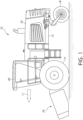
- Crop processors and forage macerators may be disposed in a crop harvesting machine such as the one illustrated in Fig. 1 .
- a side elevational view of a self-propelled crop harvesting machine 10 is shown being operable to cut and collect standing crop in a field, condition the cut crop as it moves through a mower conditioner machine to improve its drying characteristics, and then return the cut and conditioned crop material to the field in a windrow or swath.
- the crop harvesting machine is also known as a mower conditioner or a windrower.
- the crop harvesting machine 10 moves along the field in a working direction 11.
- the crop harvesting machine 10 includes a main frame 12 supported on driven right and left front wheels, of which only the left front wheel 14 (with respect to the operator) is shown and on right and left caster mounted rear wheels, of which only a left rear wheel 18 is shown.
- a cab 20 is mounted on a forward end of the frame 12, and a housing 22 within which is located a prime mover (not shown), such as an internal combustion engine, is mounted on the frame 12 behind the cab 20.
- a harvesting header 24 is coupled to and supported by the forward end of the frame 12. Operator controls (not shown) are provided in the cab 20 for operation of the crop harvesting machine 10, including the attached harvesting header 24.
- the harvesting header in one embodiment, includes one or more ground engaging devices, such as one or more skid shoes or wheels (not shown), to support the harvesting header 24 during movement across a field.
- the harvesting header does not include a traction drive. All of its power comes from the windrower traction unit or the tractor.
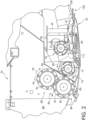
- the harvesting header 24 is shown in greater detail in Fig. 2 .
- the header 24 includes a frame or chassis to which crop cutting and conditioner elements are coupled.
- the crop cutting element may be referred to as a crop-cutting member and the crop conditioner element may be referred to as a crop-conditioning member.
- the harvesting header 24 extends along a direction which defines a crop cutting width provided by a cutterbar 34.
- the cutterbar 34 is transverse with respect to the moving direction 11 of the windrower 10 of FIG. 1 . In one embodiment, the cutterbar 34 is aligned substantially perpendicularly to the moving direction 11 of the windrower 10.
- the mower conditioner is either pushed or pulled by a tractor such that the cutterbar 34 is operated generally perpendicularly to the direction of travel and either parallel to the ground or with the front edge of the cutterbar tipped lower than the back edge.
- crop (not shown) is cut at a leading edge 106 by a plurality of rotary cutter knives 108.
- the cutterbar 34 may include a substantially planar support member which extends from one side of the frame to another side thereof.
- the support member is configured to support a plurality of rotary cutters 42, each of which is supported by the support member for rotation about respective centers each defining a rotational axis.
- the plurality of rotary cutters 42 define a rotary cutter zone which extend longitudinally along the cutter bar 34 in which crop is cut, and cut crop moves across the rotary cutters 42.
- a converging drum 46 is located above a rotary cutter 42.
- a second converging drum may be located on the other side of the cutterbar 34 such that each of the converging drums are operatively connected to the respective rotary cutters 42A and 42B. As such, the converging drums move in the same rotational directions as the respective rotary cutter 42A and 42B.
- a third converging drum 50 is located adjacently to the converging drum 46 and rotates in the same direction as the converging drum 46.
- a fourth converging drum may be located on the other side of the cutterbar 34 from what is illustrated in Fig. 2 .
- the converging drum 50 may be driven by a belt (not shown) which operatively couples the drum 50 to its adjacent drum 46. Due to the rotation of the converging drums, crop cut toward the sides of the cutterbar 34 is directed toward the middle or centerline of the header 24.
- An undershot rotating auger 52 is supported by the frame for rotational movement about a rotational axis 54 along direction 60, as shown in Fig. 2 .
- the undershot rotating auger 52 includes a length which extends along the longitudinal direction and between the converging drum 50 on one side of the cutterbar 34 and the corresponding drum on the other side.
- the undershot rotating auger 52 may include one or more flightings for moving crop towards the centerline and into a space 112 between the auger 52 and a paddle section (not shown). Cut crop, therefore, is moved away from the converging drum 50 toward the centerline X by the undershot rotating auger 52 where it is pushed toward the rear of the rotary cutters 42 by paddles of the paddle section and further toward an overshot rotating auger 72.
- the overshot rotating auger 72 of Fig. 2 is supported by the frame for rotational movement in a direction 74 which is opposite the rotational direction 60 of the undershot rotating auger 52.
- the overshot rotating auger 72 includes crop movement features of the same type as the undershot rotating auger 52.
- the opposed rotations of undershot rotating auger 52 and overshot rotating auger 72 move the cut crop between the two augers 52 and 72 along a path 80 as shown in Fig. 2 .
- the path 80 extends toward an interface 82 located at a conditioner element 84, which in the illustrated embodiment includes a first conditioner roll 86 and a second conditioner roll 88.
- the first conditioner roll 86 moves in a direction 90 which is opposite a direction 92 of the second conditioner roll 88.
- Each of the conditioner rolls 86 and 88 include a plurality of extensions or splines 94 extending from a cylindrical portion 96.
- the splines 94 of one roll 86 mesh with the splines 94 of the other roll 88 such that the cut crop moving along the path 80 and into the interface 82 is conditioned by pressing, crushing, or breaking the cut crop to reduce the rigidity of the cut crop, as well as to remove or at least release a waxy outer layer which can be found in the cut crop depending on the type of cut crop being conditioned.
- the crop is conditioned by passing between the first roll 86 and the second roll 88 and out a back portion 98 of the harvesting header 24 (or mower conditioner). The cut crop then moves to the field where it remains until use or collection.
- the crop harvesting machine is shown and described above as a self-propelled windrower or mower conditioner machine.
- the teachings and principles of the present disclosure may be applied to another crop harvesting machine such as a baler.
- this disclosure is not intended to be solely limited to a crop harvesting machine.
- Other work machines in the agricultural industry that may utilize a macerator system as disclosed herein are contemplated by this disclosure.
- a macerator In the crop harvesting process, it may be desirable to place a macerator at a location after the crop is cut.
- a crop processor or crop-conditioning member may be positioned rearward of the cutterbar 34 and rotary cutters 42. As described, the crop processor can macerate or shred the crop passing therethrough in order to increase the forage digestibility characteristics and drying rates.
- An example of a conventional roll shredding macerator is illustrated in Fig. 3 .
- the RSM 300 may include a plurality of rolls that are rotatably driven at various speeds and directions for macerating an incoming crop 322.
- the crop 322 may enter the RSM 300 at an inlet 322 and exit via an outlet 336.
- the plurality of rolls may include a first roll 302, a second roll 304, a third roll 306, a fourth roll 308, a fifth roll 310, a sixth roll 312, and a seventh roll 314.
- the second, fourth and sixth rolls are positioned above the first, third, fifth and seventh rolls.
- the second, fourth and sixth rolls rotate in a counterclockwise direction 318, whereas the first, third, fifth, and seventh rolls are rotatably driven in a clockwise direction 316.
- the crop 320 As the crop 320 flows into the RSM 300, it is shredded in a maceration zone defined between the inlet 322 and the outlet 336.
- the crop 320 is pinched or shredded at a first maceration location 324 located between the first and second rolls, a second maceration location 326 located between the second and third rolls, a third maceration location 328 between the third and fourth rolls, a fourth maceration location 330 between the fourth and fifth rolls, a fifth maceration location 332 between the fifth and sixth rolls, and a sixth maceration location 334 between the sixth and seventh rolls.
- the clearance at each of the aforementioned maceration locations is minimal in order that the crop is shredded by the pair of rolls.
- the underlying issue or problem with the conventional RSM 300 of Fig. 3 is that the crop resides in each maceration zone for a very limited amount of time. After the crop exits one maceration zone, it is allowed to expand before it enters another maceration zone. As a result, the degree of maceration is limiting in view of this design.
- a belt shredding macerator system 400 is illustrated having a first or upper macerator assembly 402 and a second or lower macerator assembly 404.
- the macerator system 400 includes an inlet side 430 in which a piece of crop 428 enters and an outlet side 432 through which the crop 428 exits.
- each macerator assembly includes at least two rolls, gears, drums, pulleys, or the like, and a belt operably driven in-between.
- the first macerator assembly 402 includes a first inlet roll 406 and a first outlet roll 410.
- a drive belt 420 surrounds both rolls as shown.
- the drive belt 420 is engaged with the rolls 406, 410 such that the drive belt 420 moves or rotates around the rolls 406, 410 at a first speed or velocity, V 1 when the rolls 406, 410 rotate.
- the second macerator assembly 404 includes a second inlet roll 408 and a second outlet roll 412, with a second drive belt 422 surrounding and engaged with the rolls 408, 412.
- the second drive belt 422 moves or rotates around the rolls 408, 412 at a second speed or velocity, V 2 when the rolls 408, 412 rotates.
- either the inlet roll or outlet roll may be operably driven by a motor, engine, prime mover, or other means.
- both inlet rolls may be drive gears that are operably driven by a drive shaft coupled to a motor.
- the inlet or outlet rolls may be driven by a power take-off (PTO) from a tractor or other vehicle.
- PTO power take-off
- the first inlet roll 406 is configured to rotate about a first rotational axis 407
- the first outlet roll 410 is configured to rotate about a second rotational axis 411
- the second inlet roll 408 is configured to rotate about a rotational axis 409
- the second outlet roll 412 is configured to rotate about a rotational axis 413.
- the first inlet roll 406 and first outlet roll 410 may be operably rotated in a first direction 418
- the second inlet roll 408 and second outlet roll 412 may be operably rotated in a second direction 416.
- the first direction 418 may correspond with a counterclockwise direction
- the second direction 416 may correspond with a clockwise direction.
- the shredding macerator system 400 further includes support frames for removing or reducing any slack in the drive belts.
- the first macerator assembly 402 includes a first support frame 424 and the second macerator assembly 404 includes a second support frame 426.
- Each support frame may be designed in any known way.
- the support frames are structured as a longitudinal plate that extends a distance between the input and output rolls. Each belt comes into contact with the frames during operation. The belts are in continuous contact with the support frames.
- the maceration zone 414 defines a continuous passageway 425 extending the distance between the first rotational axis 407 and the second rotational axis 411.
- the passageway includes a first end defining an inlet 431 of the passageway 425 adjacent the first rotational axis 407 and second end defining an outlet 433 of the passageway 425 adjacent the second rotational axis 411.
- the crop 428 is effectively shredded or macerated during its entire travel through the zone 414.
- the conventional system is arranged such that the crop is effectively macerated only at each "nip" or location where it is compressed between a pair of rollers.
- the crop may be effectively macerated along the entire maceration zone 414.
- the maceration zone 414 of Fig. 4 may include a few characteristics that improve or boost the level of maceration that occurs therein.
- the speed or velocity, V 1 of the first maceration belt 420 may be different from the speed or velocity, V 2 , of the second maceration belt 422.
- This differential speed may be controlled to achieve the desired level of maceration. If the differential speed is minimal, then the crop may not be macerated as much as when the differential speed is greater.
- a control system may be part of the system 400 in which a controller (not shown) operably controls the longitudinal speed of both belts in the maceration zone 414.
- both inlet rolls may have a larger diameter than the outlet rolls.
- the larger inlet roll diameter can make it easier to feed crop into the macerator system 400.
- the smaller diameter outlet rolls can allow for the removal of any crop that sticks or otherwise becomes caught on either belt at the outlet 432. As the belt moves around the smaller diameter outlet rolls, the flex or fluctuation of the belts can assist with removing the crop therefrom. As a result, the difference in diameters between the inlet and outlet rolls can assist with feeding the crop at the inlet 430 and discharging it at the outlet 432.
- FIG. 4 Another feature of the maceration system 400 of Fig. 4 is the distance or clearance between the first belt 420 and second belt 422.
- a first clearance at the inlet rolls 406, 408 is represented as D 1 and a second clearance at the outlet rolls 410, 412 is represented as D 2 .
- the first clearance may be greater than the second clearance such that the maceration zone 414 progressively narrows to form a wedge-like shape from the inlet 430 to the outlet 432.
- the crop 428 is exposed to two abrading surfaces or belts which are in close proximity to one another for a relatively large surface area or longitudinal distance compared to a single nip.
- the system 400 of Fig. 4 may be referred to as a large surface area macerator having an endless, textured maceration surface for macerating crop.
- the maceration zone 414 has a defined length, L, and the longer this length is the greater opportunity for maceration exists. In other words, not only is it desirable to have a longer length, but the greater length further allows for additional abrading time of the crop 428 between the belts.
- An additional feature of the system 400 of Fig. 4 which can impact maceration is the grit texture of the first and second drive belts. For example, if the belts have a fine texture, then the crop 428 may experience less maceration. If, however, the belts have a more coarse texture, then the crop 428 may be exposed to greater maceration.
- the amount of force applied to the crop 428 passing through the maceration zone 414 by the first belt 420 and second belt 422 can also impact maceration.
- the first and second support frames can limit or reduce flexing or sagging of the belts during operation to maintain a compressive force on the crop. If a greater force is applied to the crop 428 passing through the maceration zone 414, then more cells of the crop 428 will be sheared or abraded once it exits via the outlet 432.
- the first and second belts 420, 422 come into contact at one or more locations along their length with the respective support frame 424, 426 to further give shape to each belt.
- each belt comes into contact along the entire length of the respective support frame.
- the surface of the respective support frame may comprise a low friction material to help smooth travel of the belt along the frame.
- the belt may be formed of a lower friction material as well. This may also be the case with the first belt 420 and the first support frame 422.
- the macerator configuration of Fig. 4 has several potential advantages over the conventional RSM 300 of Fig. 3 .
- the system 400 may have fewer moving components while providing considerably greater processing area.
- the crop mat expands after each nip and then must be recompressed as the mat passes to the next nip. Compressing and releasing the mat is inefficient, so the continuous compaction of the belt shearing macerator system 400 can be more energy efficient.
- the belts may be heavy-duty industrial abrasive belts that are commercially available and which may be cost effective and easily replaceable. With the RSM 300, the rolls must be re-machined in order to resurface them, which can be very costly.
- different textures or grits
- a belt 800 in the form of a conveyor or carrier belt is shown. This belt 800 may be part of the lower, second macerator assembly 404 of Fig. 4 .
- the belt 800 may include a pattern 802 formed in the belt material for directing crop material that enters at an inlet 804 and travels to an exit 806 to move towards a center or middle portion 810 thereof.
- the upper, abrasive belt 420 of the first macerator assembly 402 may include a pattern formed therein similar to that of belt 800.
- the upper, abrasive belt 420 is operably driven at a differential speed compared to that of the lower, patterned belt 422. If the upper, abrasive belt 420 is driven at a faster speed than the lower, patterned belt 422, the crop material 428 may be moved inwardly towards the center of the lower belt 422 (or center of the maceration zone 414). If the lower, patterned belt 422 is driven at a faster speed than the upper, abrasive belt 420, the crop material 428 may be more evenly spread out across the width of the belts and maceration zone 414. As the crop is more evenly spread, the mat of crop material may be made thinner which may improve the level of maceration.
- the patterned belt may comprise abrasive material embedded on the "higher surfaces" of the belt.
- the pattern 802 may form channels in the belt material, whereas the surfaces of the belt that do not form the channels may include abrasive material.
- a different embodiment of a belt 900 in the form of a conveyor or carrier belt is shown.
- the belt 900 may include a different, arc-shaped pattern 902 for directing crop towards a center portion 910 thereof.
- the belt pattern 902 may assist with moving the crop towards the center portion 910.
- the belt 1000 may too be a conveyor or carrier belt.
- the belt 1000 may include a different pattern 1002 for assisting with moving the crop inwardly toward a center portion 1010 thereof. Again, the crop enters via an inlet 1006 and travels to an outlet 1008 of the system.
- Figs. 6-8 While three different examples are shown in Figs. 6-8 , it is to be understood that these are only intended to represent non-limiting examples of a belt pattern. Other patterns that assist with moving crop towards a center portion of the belt may be contemplated by this disclosure. Moreover, these patterned belts can assist with preventing or reducing the likelihood of crop falling off the belts. Moreover, the crop may roll laterally inwardly toward the center of the belt, and as it does, the crop material may be subjected to maceration along two-dimensions or directions (i.e., in the lateral and longitudinal directions). The two directions of shear may improve fiberization of the crop material. Although not shown, the top belt or the belt 420 of the first macerator system 402 may comprise sand paper or the like.
- the embodiments of Figs. 7 and 8 may also include belts with both patterns and abrasive surfaces. Further, the belts 900, 1000 may also be used in combination with another belt such that the pair of belts are operated at differential speeds to either assist with moving the crop inwardly toward a center portion or spreading the crop more evenly across a width of the maceration zone to improve maceration.
- a wedge-shaped platen maceration system 700 is illustrated.
- the system includes a first macerator assembly 702 and a second macerator assembly 704.
- the first macerator assembly 702 includes a first inlet roll 706 and a first outlet roll 708.
- the inlet roll 706 and outlet roll 708 are operably driven by a motor or other power-generating device in a first rotational direction 718.
- the first rotational direction 718 corresponds with the counterclockwise direction.
- the inlet roll 706 is configured to rotate about a first rotational axis 707
- the outlet roll 708 is configured to rotate about a second rotational axis 709.
- the first macerator assembly 702 also includes a first abrasive belt 714 which is operably driven at a first speed or velocity, V 1 , and supported by the rolls. Further, the first macerator assembly 702 includes a first support frame 726. Unlike the support frame of Fig. 4 , however, the first support frame 726 has an elongated body defined by a substantially horizontal first portion 730 and an angled second portion 732. The substantially horizontal portion 730 may be described as linear meaning that it extends in a straight line. Additionally, angled second portion 732 is disposed at an angle relative to the horizontal portion 730, yet the angled second portion 732 may be described as linear meaning that it extends in a straight line as well.
- the first portion 730 and second portion 732 diverge from one another at a first bend 734.
- the first belt 714 is supported by the first support frame 726 as it is driven by the rolls. Moreover, the first support frame 726 ensures that the belt 714 does not sag or flex in the area of a maceration zone formed by the system 700.
- the second macerator assembly 704 includes a second inlet roll 710 and a second outlet roll 712.
- the inlet roll 710 and outlet roll 712 are operably driven by a motor or other power-generating device (not shown) in a second or clockwise direction 720.
- the inlet roll 710 is configured to rotate about a first rotational axis 711
- the outlet roll 712 is configured to rotate about a second rotational axis 713.
- the first and second directions are opposite from one another.
- a second abrasive belt 716 is operably driven at a second speed or velocity, V 2 , and supported by the rolls 710, 712 such that the first belt 714 and second belt 716 travel in the same longitudinal direction in the maceration zone.
- the second macerator assembly 704 also includes a second support frame 728.
- the second support frame 728 has an elongated body defined by a substantially horizontal first portion 736 and an angled second portion 738. The first portion 736 and second portion 738 diverge from one another at a second bend 740.
- the second belt 716 is supported by the second support frame 728 as it is driven by the rolls.
- the second support frame 728 ensures that the belt 716 does not sag or flex in the area of a full maceration zone 745 formed by the system 700. As such, the belt 716 comes into contact at one or more locations along its length with the support frame 728 to further give shape to the belt.
- the belt 716 contacts the support frame 728 along the entire length of the support frame 728.
- the surface of the second support frame 728 may comprise a low friction material to help smooth travel of the belt along the frame 728.
- the inside surface of the belt 716 which contacts the support frame 728 may be formed of a lower friction material as well.
- the full maceration zone 745 is defined between an inlet side 722 through which crop enters and an outlet side 724 through which crop exits the zone. Further, the full maceration zone 745 is divided into a first maceration zone 742 and a second maceration zone 744. In the first maceration zone 742, crop enters the inlet 722 having a first width or clearance, D 1 . As the crop enters the first maceration zone 742, however, the distance between the belts 714, 716 begins to taper inwardly such that the clearance continuously decreases. This inward tapering of the first maceration zone 742 continues until the transition between the first and second maceration zones.
- the clearance or distance between the belts may be defined as D 2 .
- D 2 represents a clearance that is smaller than D 1 .
- D 1 it may be easier to feed crop into the inlet side 722 of the maceration system 700 due to the increased clearance, D 1 , whereas the crop is more likely to experience greater maceration due to the decreased clearance of the second maceration zone 744.
- the clearance is represented as D 3 .
- the clearance, D 3 may be the same as, smaller than, or larger than the clearance, D 2 .
- the dimensions of D 1 , D 2 , and D 3 can be the same as, smaller than, or larger than each other in any arrangement or combination.
- the second maceration zone 744 may have a substantially constant clearance, D2, through its entire longitudinal length. This ensures that the crop is subjected to a greater shearing effect and better maceration in this area than in the first maceration zone 742. For this reason, it may be desirable to design the second maceration zone 744 to have a greater longitudinal length than the first maceration zone 742.
- the full maceration zone 744 may be defined between (or in other words bounded by) the belts 714, 716.
- the full maceration zone 745 defines a continuous passageway 725.
- the passageway 725 includes a first end defining an inlet 723 of the passageway 725 adjacent the first rotational axis 707 and a second end defining an outlet 727 of the passageway 725 adjacent the second rotational axis 709.
- the full maceration zone 745 includes a rectangular portion 744 and a wedge-shaped portion 742 adjacent the rectangular portion.
- the maceration zones of Figs. 4 and 5 are illustrated as being substantially linear in a longitudinal direction. However, in other embodiments, these maceration zones may have a curvature or arc to the overall shape. Thus, it is not required for the maceration zones to be linear, and any desirable shape or orientation is possible.
- the characteristics described above with respect to the belt shredding maceration system 400 of Fig. 4 may be equally applied to the system of Fig. 5 or any deviation or combination thereof to achieve different degrees of maceration.
- changes in clearance between the belts, differential speeds, grit textures of the belts, surface area of the maceration zone, abrasion time in the maceration zone, and the force applied to the crop by the belts may be made to modify the degree of maceration of the crop.
- the belt may be any endless member including a chain or other known device.
- the belts in the aforementioned embodiments may be capable of being driven in an oscillatory manner.
- either belt in the aforementioned maceration systems may be oscillated in a lateral or side-to-side direction with respect to the other belt. It may be simply possible to move the belt only via the oscillatory movement. In doing so, it may be possible to further break down the plant stem and cell walls of the crop material.
- belts that can be easily removed and replaced.
- the interchangeability of the belts may improve the efficiency of each system and allow for greater productivity. Further, it may improve energy losses and the like in the system.
- any of the aforementioned embodiments or deviations therefrom may be incorporated at the time of cutting crop such as hay.
- the crop for example, may be first cut in a field, fed into the macerator system where the crop material is shredded and then deposited on a conveyor belt or other mechanism where it is pressed into a mat.
- the macerator system may also be incorporated into the forage harvester.
- today crop is cut and discharged onto a field where it is able to at least partially dry.
- a forage harvester or baler may then come along to harvest the crop.
- the crop may be placed in a square or round bale, or a self-propelled harvester may collect the crop and chop it up further before the crop is placed in a bunk silo.
- the macerator system may be incorporated into the harvester between the pickup unit of the baler and the baling chamber.
- the crop may be macerated after it is collected from the field but before the crop is formed into a bale.
- the macerator system may replace a conventional crop processor in the forage harvester. To do so, however, the harvester will require a redesign in an effort to incorporate the macerator system in place of the crop processor.
- the macerator system may be designed as its own standalone system. In this embodiment, the macerator system may be used to macerate the crop before it is placed in the bunk silo.
- the macerator system of the present disclosure may be used to macerate the crop after it comes out of the bunk silo and before it is fed to cattle, for example.
- the crop's cell wall may be ruptured during maceration in order to fiberize the fibrous portions of the plant material to improve digestion.
- bacteria digests or eats sugars in the plant and excretes acids usually in the form of lactic acid.
- the macerator system may be used in the process after the crop has been stored in the bunk silo and is ready to be fed to cattle or other animals.
- the harvesting system may require modification. For instance, a baler or self-propelled harvester may need to be redesigned to include the maceration system.
- machines may need to be modified to pick up a mat of crop instead of a windrow. Some of these changes, particularly to the machine, can be expensive.
- the overall goal is only to improve digestibility and not improving drying time, then it may be less disruptive and cheaper to incorporate the maceration system downstream of the overall harvesting process.
- the required capacity or power to operate the maceration system may be significantly lower than if the system were to be incorporated into a harvesting machine. One reason for this is because the maceration system would not require the same level of power to keep up chopping rotors in the harvester.
Landscapes
- Life Sciences & Earth Sciences (AREA)
- Environmental Sciences (AREA)
- Crushing And Pulverization Processes (AREA)
- Harvester Elements (AREA)
Claims (6)
- Machine agricole comprenant :un châssis ;un élément de coupe de récolte accouplé au châssis ; etun élément de conditionnement de récolte accouplé au châssis et positionné à l'arrière de l'élément de coupe de récolte,l'élément de conditionnement de récolte comprenant un premier ensemble broyeur (402, 702) comprenant un premier rouleau d'entrée (406, 706) conçu pour tourner autour d'un premier axe de rotation (407, 707), un premier rouleau de sortie (410, 708) conçu pour tourner autour d'un deuxième axe de rotation (411, 709), et un premier élément sans fin (420, 714) entourant et en prise avec le premier rouleau d'entrée (406, 706) et le premier rouleau de sortie (410, 708),l'élément de conditionnement de récolte comprenant un second ensemble broyeur (404, 704) espacé du premier ensemble broyeur (402, 702), le second ensemble broyeur (402, 702) comprenant un second rouleau d'entrée (408, 708) conçu pour tourner autour d'un troisième axe de rotation (409, 709), un second rouleau de sortie (412, 712) conçu pour tourner autour d'un quatrième axe de rotation (413, 713), et un second élément sans fin (422, 722) entourant et en prise avec le second rouleau d'entrée (408, 708) et le second rouleau de sortie (412, 712) ;l'élément de conditionnement de récolte comprenant une zone de broyage (414, 742, 744, 745) délimitée par le premier élément sans fin (420, 714) et le second élément sans fin (422, 722) et la zone de broyage (414, 742, 744, 745) définissant un passage continu (425, 725) s'étendant sur la distance entre le premier axe de rotation (407, 707) et le deuxième axe de rotation (411, 709) et le passage continu (425, 725) comprenant une première extrémité définissant une entrée du passage (431, 723) adjacente au premier axe de rotation (407, 707), et une seconde extrémité définissant une sortie du passage (433, 727) adjacente au deuxième axe de rotation (411, 709) ;caractérisé en ce que le premier élément sans fin (420, 714) est conçu pour être entraîné par rapport au second élément sans fin (422, 722) avec une vitesse différentielle pour broyer la récolte disposée entre le premier élément sans fin (420, 714) et le second élément sans fin (422, 722) ;en ce que le premier ensemble broyeur (402, 702) comprend un premier cadre de support (424, 726) qui comprend une première extrémité et une seconde extrémité, le premier cadre de support (424, 726) étant structuré comme une plaque longitudinale positionnée entre le premier rouleau d'entrée (406, 706) et le premier rouleau de sortie (410, 708), et le premier cadre de support (424, 726) étant entouré par et conçu pour venir en prise avec le premier élément sans fin (420, 714) sur toute la longueur du premier cadre de support (424, 726) définie entre la première extrémité et la seconde extrémité du cadre de support (424, 726), et en ce que le second ensemble broyeur (404, 704) comprend un second cadre de support (426, 728) qui comprend une première extrémité et une seconde extrémité, le second cadre de support (426, 728) étant structuré comme une plaque longitudinale positionnée entre le second rouleau d'entrée (408, 708) et le second rouleau de sortie (412, 712), et le second cadre de support (426, 728) étant entouré par le second élément sans fin (422, 722) et conçu pour venir en prise avec celui-ci sur toute la longueur du second cadre de support (426, 728) définie entre la première extrémité et la seconde extrémité du second cadre de support (426, 728).
- Machine agricole selon la revendication 1, le premier rouleau d'entrée (406, 706) ayant un premier diamètre, et le premier rouleau de sortie (410, 708) ayant un second diamètre plus petit que le premier diamètre.
- Machine agricole selon la revendication 1, la zone de broyage (414, 742, 744, 745) comprenant une partie rectangulaire et une partie en forme de coin adjacente à la partie rectangulaire.
- Machine agricole selon la revendication 3, l'entrée du passage continu (431, 723) étant définie dans la partie en forme de coin de la zone de broyage (414, 742, 744, 745), et la sortie du passage continu (433, 727) étant définie dans la partie rectangulaire de la zone de broyage (414, 742, 744, 745).
- Machine agricole selon la revendication 4, les cadres de support (726, 728) comprenant chacun une première partie sensiblement linéaire conçue pour venir en prise avec le premier ou le second élément sans fin (714, 722) et les cadres de support (726, 728) comprenant une seconde partie sensiblement linéaire conçue pour venir en prise avec le premier ou le second élément sans fin (714, 722), et la seconde partie sensiblement linéaire étant disposée à un angle par rapport à la première partie sensiblement linéaire.
- Machine agricole selon la revendication 1, le second ensemble broyeur (404, 704) étant sensiblement identique au premier ensemble broyeur (402, 702).
Applications Claiming Priority (2)
| Application Number | Priority Date | Filing Date | Title |
|---|---|---|---|
| US201862728123P | 2018-09-07 | 2018-09-07 | |
| PCT/US2019/046487 WO2020050958A1 (fr) | 2018-09-07 | 2019-08-14 | Système agricole comprenant un broyeur de déchiquetage et son procédé |
Publications (3)
| Publication Number | Publication Date |
|---|---|
| EP3846609A1 EP3846609A1 (fr) | 2021-07-14 |
| EP3846609A4 EP3846609A4 (fr) | 2022-06-01 |
| EP3846609B1 true EP3846609B1 (fr) | 2024-10-23 |
Family
ID=69722556
Family Applications (1)
| Application Number | Title | Priority Date | Filing Date |
|---|---|---|---|
| EP19857338.8A Active EP3846609B1 (fr) | 2018-09-07 | 2019-08-14 | Système agricole comprenant un broyeur de déchiquetage et son procédé |
Country Status (5)
| Country | Link |
|---|---|
| US (1) | US11871699B2 (fr) |
| EP (1) | EP3846609B1 (fr) |
| CN (1) | CN112638149B (fr) |
| CA (1) | CA3111973A1 (fr) |
| WO (1) | WO2020050958A1 (fr) |
Families Citing this family (6)
| Publication number | Priority date | Publication date | Assignee | Title |
|---|---|---|---|---|
| US20220022416A1 (en) * | 2020-07-21 | 2022-01-27 | Deere & Company | Method and system for preparing a feed ration based on degree of maceration |
| US11758926B2 (en) * | 2020-07-21 | 2023-09-19 | Deere & Company | Setting degree of maceration based on forage nutritive values |
| US20220046852A1 (en) * | 2020-08-11 | 2022-02-17 | Deere & Company | Mechanism for sensing vibration in conditioner rollers |
| DE102022118227A1 (de) * | 2022-07-21 | 2024-02-01 | CLAAS Hungária Kft. | Bandschneidwerk |
| KR102858460B1 (ko) * | 2022-12-01 | 2025-09-12 | 김재동 | 옥수수 수확장치 |
| US20240423136A1 (en) * | 2023-06-20 | 2024-12-26 | Cnh Industrial America Llc | Conveying system for an agricultural harvester |
Family Cites Families (34)
| Publication number | Priority date | Publication date | Assignee | Title |
|---|---|---|---|---|
| US2829587A (en) * | 1953-08-03 | 1958-04-08 | Case Co J I | Forage crop crusher |
| DE1939784C3 (de) * | 1969-08-05 | 1978-08-24 | Maschinenfabrik J. Dieffenbacher Gmbh & Co, 7519 Eppingen | Kontinuierlich arbeitende Presse zur Herstellung von Spanplatten, Faserplatten, Sperrholzplatten o.dgl |
| US4068453A (en) * | 1976-06-28 | 1978-01-17 | Avco Corporation | Drive system for hay harvesting and conditioning machine |
| US4185786A (en) | 1976-08-11 | 1980-01-29 | Lehampton Farms, Inc. | Rotary extrusion apparatus |
| US4109448A (en) | 1976-08-11 | 1978-08-29 | Schoeneck Farms, Inc. | Method and apparatus for in-field processing of vegetation |
| US4265076A (en) | 1978-04-28 | 1981-05-05 | Purdue Research Foundation | Device for treating agricultural products to enhance drying |
| US4332125A (en) * | 1980-08-19 | 1982-06-01 | Holdren Richard D | Apparatus and method for producing highly nutritive storage stable forage plant material |
| US4325209A (en) | 1981-04-28 | 1982-04-20 | International Harvester Company | Method and apparatus for in-field crop harvesting |
| US4445313A (en) * | 1982-08-19 | 1984-05-01 | Thomas Elliott | Hay cutting machines |
| NL8501602A (nl) * | 1985-06-04 | 1987-01-02 | Multinorm Bv | Inrichting voor het bewerken van voedergewassen. |
| US4912914A (en) * | 1988-08-29 | 1990-04-03 | Wingard Steve G | Method and apparatus for drying forage crops |
| DE3912437A1 (de) * | 1989-04-15 | 1990-10-18 | Wilhelm Von Allwoerden | Verfahren und vorrichtung zur gruenfutteraufbereitung |
| DE3940673A1 (de) | 1989-07-17 | 1991-06-13 | Khd Agrartechnik | Selbstfahrende erntemaschine |
| US5152127A (en) * | 1991-06-21 | 1992-10-06 | The United States Of America, As Represented By The Secretary Of Agriculture | Process and apparatus to improve the properties and value of forage crops |
| DE4228857A1 (de) * | 1992-08-29 | 1994-03-03 | Kloeckner Humboldt Deutz Ag | Vorrichtung zur Halmgutaufbereitung |
| DE4229060A1 (de) * | 1992-09-01 | 1994-03-03 | Kloeckner Humboldt Deutz Ag | Erntemaschine zur Grünfutteraufbereitung |
| DE4231923A1 (de) * | 1992-09-24 | 1994-03-31 | Kloeckner Humboldt Deutz Ag | Erntemaschine |
| CA2133544A1 (fr) | 1994-10-03 | 1996-04-04 | Philippe Savoie | Machine de conditionnement de forage |
| DE19531918B4 (de) | 1995-08-30 | 2005-02-24 | Maschinenfabrik Kemper Gmbh & Co. Kg | Maschine zum reihenunabhängigen Mähen und Häckseln von Mais u. dgl. stengelartigem Erntegut |
| US6055799A (en) * | 1995-10-04 | 2000-05-02 | Universite Laval & Agriculture Et Agro-Alimentaire Canada | Forage conditioning machine |
| US5894716A (en) * | 1996-06-28 | 1999-04-20 | New Holland North America, Inc. | Apparatus for macerating plant material |
| US5950406A (en) | 1996-06-28 | 1999-09-14 | New Holland North America, Inc. | Method and apparatus for macerating plant material |
| US6062010A (en) | 1997-08-04 | 2000-05-16 | New Holland North America, Inc. | Apparatus for treating plant material |
| US6032446A (en) * | 1998-04-06 | 2000-03-07 | Deere & Company | Densification method and apparatus for harvested cotton or other similar fibrous material |
| AUPR638301A0 (en) * | 2001-07-13 | 2001-08-09 | Innotech Pty Ltd | Hay conditioner |
| US7059108B1 (en) * | 2005-03-30 | 2006-06-13 | Deere & Company | Crop deflector used with crop conditioner rolls for effecting formation of fluffy windrow |
| US8006470B2 (en) * | 2005-10-11 | 2011-08-30 | Agco Corporation | Crop harvester having metal conditioner rolls with herringbone rib pattern |
| US7726108B1 (en) * | 2009-01-14 | 2010-06-01 | Agco Corporation | Wide cut rotary harvester having cut crop feeder mechanism |
| US8984851B2 (en) * | 2011-11-01 | 2015-03-24 | Agco Corporation | Chopper attachment to improve conditioning of bio-mass type crops |
| US8833046B2 (en) * | 2012-10-15 | 2014-09-16 | Neil Gordon Barnett | Rotary disk crop harvesting header with rearwardly shifted top conditioning roll and lower rear deflector |
| US11026369B2 (en) | 2017-01-28 | 2021-06-08 | Green Gold Development, Llc | Multipurpose leaf crop harvesting apparatus and processing method |
| CN207167115U (zh) | 2017-08-01 | 2018-04-03 | 山西省农业科学院玉米研究所 | 一种复合型玉米秸秆拉茎切碎装置 |
| US10736270B2 (en) * | 2017-12-27 | 2020-08-11 | Agco Corporation | Rotary header windguard |
| CN109005930B (zh) * | 2018-09-10 | 2020-07-31 | 铜陵市兆林工贸有限责任公司 | 一种农作物秸秆粉碎还田装置 |
-
2019
- 2019-08-14 CN CN201980056031.XA patent/CN112638149B/zh active Active
- 2019-08-14 CA CA3111973A patent/CA3111973A1/fr active Pending
- 2019-08-14 WO PCT/US2019/046487 patent/WO2020050958A1/fr not_active Ceased
- 2019-08-14 EP EP19857338.8A patent/EP3846609B1/fr active Active
- 2019-08-14 US US17/266,859 patent/US11871699B2/en active Active
Also Published As
| Publication number | Publication date |
|---|---|
| BR112021002749A2 (pt) | 2021-07-27 |
| EP3846609A4 (fr) | 2022-06-01 |
| WO2020050958A1 (fr) | 2020-03-12 |
| CN112638149B (zh) | 2023-07-21 |
| US20210289704A1 (en) | 2021-09-23 |
| EP3846609A1 (fr) | 2021-07-14 |
| CA3111973A1 (fr) | 2020-03-12 |
| US11871699B2 (en) | 2024-01-16 |
| CN112638149A (zh) | 2021-04-09 |
Similar Documents
| Publication | Publication Date | Title |
|---|---|---|
| EP3846609B1 (fr) | Système agricole comprenant un broyeur de déchiquetage et son procédé | |
| EP2168427B1 (fr) | Machine de récolte | |
| US6412259B1 (en) | Gathering roller mechanism for harvesting device and harvesting device utilizing same | |
| US6874311B2 (en) | Crop recovery machine | |
| EP2992753A1 (fr) | Moissonneuse avec plancher inférieur arrière actif | |
| EP1358788B1 (fr) | Unité de transformation de végétaux et agencement de soufflerie pour une recolteuse-hacheuse de fourrage | |
| US5661961A (en) | Crop processor for round hay balers | |
| EP0058431B1 (fr) | Machine à récolter les fourrages | |
| EP3542610A1 (fr) | Ramasseuse-hacheuse | |
| US20040060271A1 (en) | Agricultural harvesting machines and front attachments therefor | |
| US4248248A (en) | Interrupted infeed flight means for combine rotor | |
| JP5651870B2 (ja) | 甘藷つる収穫機 | |
| EP3016497B1 (fr) | Commande de mécanismes d'entraînement dans une moissonneuse agricole | |
| GB2092086A (en) | Screw conveyor | |
| JP2012005450A (ja) | 甘藷つる収穫機 | |
| US12262660B2 (en) | Agricultural implement for field-collection, pulverization and field-dispersement of flax or hemp straw | |
| JP6712281B2 (ja) | 農業機械 | |
| EP1532860A1 (fr) | Déchiqueteuse agricole | |
| BR112021002749B1 (pt) | Máquina agrícola, e, membro de condicionamento de lavoura para uso com uma máquina agrícola | |
| EP2106686A1 (fr) | Dispositif de conditionnement pour une ramasseuse-hacheuse | |
| CN107912134B (zh) | 自走式秸秆揉丝机以及秸秆收割处理设备 | |
| RU2102855C1 (ru) | Сельскохозяйственный уборочный комбайн | |
| NL8401372A (nl) | Veldhakselmachine. | |
| JPH11266661A (ja) | 全稈投入型コンバイン |
Legal Events
| Date | Code | Title | Description |
|---|---|---|---|
| STAA | Information on the status of an ep patent application or granted ep patent |
Free format text: STATUS: THE INTERNATIONAL PUBLICATION HAS BEEN MADE |
|
| PUAI | Public reference made under article 153(3) epc to a published international application that has entered the european phase |
Free format text: ORIGINAL CODE: 0009012 |
|
| STAA | Information on the status of an ep patent application or granted ep patent |
Free format text: STATUS: REQUEST FOR EXAMINATION WAS MADE |
|
| 17P | Request for examination filed |
Effective date: 20210407 |
|
| AK | Designated contracting states |
Kind code of ref document: A1 Designated state(s): AL AT BE BG CH CY CZ DE DK EE ES FI FR GB GR HR HU IE IS IT LI LT LU LV MC MK MT NL NO PL PT RO RS SE SI SK SM TR |
|
| DAV | Request for validation of the european patent (deleted) | ||
| DAX | Request for extension of the european patent (deleted) | ||
| A4 | Supplementary search report drawn up and despatched |
Effective date: 20220503 |
|
| RIC1 | Information provided on ipc code assigned before grant |
Ipc: A01F 12/40 20060101ALI20220426BHEP Ipc: A01D 82/02 20060101ALI20220426BHEP Ipc: A01D 82/00 20060101ALI20220426BHEP Ipc: A01D 43/10 20060101AFI20220426BHEP |
|
| GRAP | Despatch of communication of intention to grant a patent |
Free format text: ORIGINAL CODE: EPIDOSNIGR1 |
|
| STAA | Information on the status of an ep patent application or granted ep patent |
Free format text: STATUS: GRANT OF PATENT IS INTENDED |
|
| INTG | Intention to grant announced |
Effective date: 20240718 |
|
| GRAS | Grant fee paid |
Free format text: ORIGINAL CODE: EPIDOSNIGR3 |
|
| GRAA | (expected) grant |
Free format text: ORIGINAL CODE: 0009210 |
|
| STAA | Information on the status of an ep patent application or granted ep patent |
Free format text: STATUS: THE PATENT HAS BEEN GRANTED |
|
| AK | Designated contracting states |
Kind code of ref document: B1 Designated state(s): AL AT BE BG CH CY CZ DE DK EE ES FI FR GB GR HR HU IE IS IT LI LT LU LV MC MK MT NL NO PL PT RO RS SE SI SK SM TR |
|
| REG | Reference to a national code |
Ref country code: GB Ref legal event code: FG4D |
|
| REG | Reference to a national code |
Ref country code: CH Ref legal event code: EP |
|
| REG | Reference to a national code |
Ref country code: DE Ref legal event code: R096 Ref document number: 602019060899 Country of ref document: DE |
|
| REG | Reference to a national code |
Ref country code: IE Ref legal event code: FG4D |
|
| REG | Reference to a national code |
Ref country code: LT Ref legal event code: MG9D |
|
| REG | Reference to a national code |
Ref country code: NL Ref legal event code: MP Effective date: 20241023 |
|
| REG | Reference to a national code |
Ref country code: AT Ref legal event code: MK05 Ref document number: 1734011 Country of ref document: AT Kind code of ref document: T Effective date: 20241023 |
|
| PG25 | Lapsed in a contracting state [announced via postgrant information from national office to epo] |
Ref country code: NL Free format text: LAPSE BECAUSE OF FAILURE TO SUBMIT A TRANSLATION OF THE DESCRIPTION OR TO PAY THE FEE WITHIN THE PRESCRIBED TIME-LIMIT Effective date: 20241023 |
|
| PG25 | Lapsed in a contracting state [announced via postgrant information from national office to epo] |
Ref country code: NL Free format text: LAPSE BECAUSE OF FAILURE TO SUBMIT A TRANSLATION OF THE DESCRIPTION OR TO PAY THE FEE WITHIN THE PRESCRIBED TIME-LIMIT Effective date: 20241023 |
|
| PG25 | Lapsed in a contracting state [announced via postgrant information from national office to epo] |
Ref country code: PT Free format text: LAPSE BECAUSE OF FAILURE TO SUBMIT A TRANSLATION OF THE DESCRIPTION OR TO PAY THE FEE WITHIN THE PRESCRIBED TIME-LIMIT Effective date: 20250224 Ref country code: HR Free format text: LAPSE BECAUSE OF FAILURE TO SUBMIT A TRANSLATION OF THE DESCRIPTION OR TO PAY THE FEE WITHIN THE PRESCRIBED TIME-LIMIT Effective date: 20241023 Ref country code: IS Free format text: LAPSE BECAUSE OF FAILURE TO SUBMIT A TRANSLATION OF THE DESCRIPTION OR TO PAY THE FEE WITHIN THE PRESCRIBED TIME-LIMIT Effective date: 20250223 |
|
| PG25 | Lapsed in a contracting state [announced via postgrant information from national office to epo] |
Ref country code: FI Free format text: LAPSE BECAUSE OF FAILURE TO SUBMIT A TRANSLATION OF THE DESCRIPTION OR TO PAY THE FEE WITHIN THE PRESCRIBED TIME-LIMIT Effective date: 20241023 |
|
| PG25 | Lapsed in a contracting state [announced via postgrant information from national office to epo] |
Ref country code: BG Free format text: LAPSE BECAUSE OF FAILURE TO SUBMIT A TRANSLATION OF THE DESCRIPTION OR TO PAY THE FEE WITHIN THE PRESCRIBED TIME-LIMIT Effective date: 20241023 |
|
| PG25 | Lapsed in a contracting state [announced via postgrant information from national office to epo] |
Ref country code: ES Free format text: LAPSE BECAUSE OF FAILURE TO SUBMIT A TRANSLATION OF THE DESCRIPTION OR TO PAY THE FEE WITHIN THE PRESCRIBED TIME-LIMIT Effective date: 20241023 |
|
| PG25 | Lapsed in a contracting state [announced via postgrant information from national office to epo] |
Ref country code: NO Free format text: LAPSE BECAUSE OF FAILURE TO SUBMIT A TRANSLATION OF THE DESCRIPTION OR TO PAY THE FEE WITHIN THE PRESCRIBED TIME-LIMIT Effective date: 20250123 |
|
| PG25 | Lapsed in a contracting state [announced via postgrant information from national office to epo] |
Ref country code: LV Free format text: LAPSE BECAUSE OF FAILURE TO SUBMIT A TRANSLATION OF THE DESCRIPTION OR TO PAY THE FEE WITHIN THE PRESCRIBED TIME-LIMIT Effective date: 20241023 Ref country code: AT Free format text: LAPSE BECAUSE OF FAILURE TO SUBMIT A TRANSLATION OF THE DESCRIPTION OR TO PAY THE FEE WITHIN THE PRESCRIBED TIME-LIMIT Effective date: 20241023 Ref country code: GR Free format text: LAPSE BECAUSE OF FAILURE TO SUBMIT A TRANSLATION OF THE DESCRIPTION OR TO PAY THE FEE WITHIN THE PRESCRIBED TIME-LIMIT Effective date: 20250124 |
|
| PG25 | Lapsed in a contracting state [announced via postgrant information from national office to epo] |
Ref country code: PL Free format text: LAPSE BECAUSE OF FAILURE TO SUBMIT A TRANSLATION OF THE DESCRIPTION OR TO PAY THE FEE WITHIN THE PRESCRIBED TIME-LIMIT Effective date: 20241023 |
|
| PG25 | Lapsed in a contracting state [announced via postgrant information from national office to epo] |
Ref country code: RS Free format text: LAPSE BECAUSE OF FAILURE TO SUBMIT A TRANSLATION OF THE DESCRIPTION OR TO PAY THE FEE WITHIN THE PRESCRIBED TIME-LIMIT Effective date: 20250123 |
|
| PG25 | Lapsed in a contracting state [announced via postgrant information from national office to epo] |
Ref country code: SM Free format text: LAPSE BECAUSE OF FAILURE TO SUBMIT A TRANSLATION OF THE DESCRIPTION OR TO PAY THE FEE WITHIN THE PRESCRIBED TIME-LIMIT Effective date: 20241023 |
|
| PG25 | Lapsed in a contracting state [announced via postgrant information from national office to epo] |
Ref country code: DK Free format text: LAPSE BECAUSE OF FAILURE TO SUBMIT A TRANSLATION OF THE DESCRIPTION OR TO PAY THE FEE WITHIN THE PRESCRIBED TIME-LIMIT Effective date: 20241023 |
|
| PG25 | Lapsed in a contracting state [announced via postgrant information from national office to epo] |
Ref country code: EE Free format text: LAPSE BECAUSE OF FAILURE TO SUBMIT A TRANSLATION OF THE DESCRIPTION OR TO PAY THE FEE WITHIN THE PRESCRIBED TIME-LIMIT Effective date: 20241023 |
|
| PG25 | Lapsed in a contracting state [announced via postgrant information from national office to epo] |
Ref country code: RO Free format text: LAPSE BECAUSE OF FAILURE TO SUBMIT A TRANSLATION OF THE DESCRIPTION OR TO PAY THE FEE WITHIN THE PRESCRIBED TIME-LIMIT Effective date: 20241023 |
|
| REG | Reference to a national code |
Ref country code: DE Ref legal event code: R097 Ref document number: 602019060899 Country of ref document: DE |
|
| PG25 | Lapsed in a contracting state [announced via postgrant information from national office to epo] |
Ref country code: SK Free format text: LAPSE BECAUSE OF FAILURE TO SUBMIT A TRANSLATION OF THE DESCRIPTION OR TO PAY THE FEE WITHIN THE PRESCRIBED TIME-LIMIT Effective date: 20241023 |
|
| PG25 | Lapsed in a contracting state [announced via postgrant information from national office to epo] |
Ref country code: CZ Free format text: LAPSE BECAUSE OF FAILURE TO SUBMIT A TRANSLATION OF THE DESCRIPTION OR TO PAY THE FEE WITHIN THE PRESCRIBED TIME-LIMIT Effective date: 20241023 |
|
| PG25 | Lapsed in a contracting state [announced via postgrant information from national office to epo] |
Ref country code: IT Free format text: LAPSE BECAUSE OF FAILURE TO SUBMIT A TRANSLATION OF THE DESCRIPTION OR TO PAY THE FEE WITHIN THE PRESCRIBED TIME-LIMIT Effective date: 20241023 |
|
| PLBE | No opposition filed within time limit |
Free format text: ORIGINAL CODE: 0009261 |
|
| STAA | Information on the status of an ep patent application or granted ep patent |
Free format text: STATUS: NO OPPOSITION FILED WITHIN TIME LIMIT |
|
| PG25 | Lapsed in a contracting state [announced via postgrant information from national office to epo] |
Ref country code: SE Free format text: LAPSE BECAUSE OF FAILURE TO SUBMIT A TRANSLATION OF THE DESCRIPTION OR TO PAY THE FEE WITHIN THE PRESCRIBED TIME-LIMIT Effective date: 20241023 |
|
| 26N | No opposition filed |
Effective date: 20250724 |
|
| PGFP | Annual fee paid to national office [announced via postgrant information from national office to epo] |
Ref country code: DE Payment date: 20250721 Year of fee payment: 7 |
|
| PGFP | Annual fee paid to national office [announced via postgrant information from national office to epo] |
Ref country code: GB Payment date: 20250827 Year of fee payment: 7 |
|
| PGFP | Annual fee paid to national office [announced via postgrant information from national office to epo] |
Ref country code: FR Payment date: 20250825 Year of fee payment: 7 |
|
| REG | Reference to a national code |
Ref country code: CH Ref legal event code: H13 Free format text: ST27 STATUS EVENT CODE: U-0-0-H10-H13 (AS PROVIDED BY THE NATIONAL OFFICE) Effective date: 20260324 |
|
| PG25 | Lapsed in a contracting state [announced via postgrant information from national office to epo] |
Ref country code: MC Free format text: LAPSE BECAUSE OF FAILURE TO SUBMIT A TRANSLATION OF THE DESCRIPTION OR TO PAY THE FEE WITHIN THE PRESCRIBED TIME-LIMIT Effective date: 20241023 |
|
| PG25 | Lapsed in a contracting state [announced via postgrant information from national office to epo] |
Ref country code: LU Free format text: LAPSE BECAUSE OF NON-PAYMENT OF DUE FEES Effective date: 20250814 |
|
| PG25 | Lapsed in a contracting state [announced via postgrant information from national office to epo] |
Ref country code: CH Free format text: LAPSE BECAUSE OF NON-PAYMENT OF DUE FEES Effective date: 20250831 |