EP3846659B1 - Vorrichtung mit riemen zum tragen eines elektronischen gerätes über die schulter gegen den brustkorb eines benutzers - Google Patents
Vorrichtung mit riemen zum tragen eines elektronischen gerätes über die schulter gegen den brustkorb eines benutzers Download PDFInfo
- Publication number
- EP3846659B1 EP3846659B1 EP19774148.1A EP19774148A EP3846659B1 EP 3846659 B1 EP3846659 B1 EP 3846659B1 EP 19774148 A EP19774148 A EP 19774148A EP 3846659 B1 EP3846659 B1 EP 3846659B1
- Authority
- EP
- European Patent Office
- Prior art keywords
- support
- strap
- electronic device
- designed
- band
- Prior art date
- Legal status (The legal status is an assumption and is not a legal conclusion. Google has not performed a legal analysis and makes no representation as to the accuracy of the status listed.)
- Active
Links
Images


Classifications
-
- A—HUMAN NECESSITIES
- A45—HAND OR TRAVELLING ARTICLES
- A45C—PURSES; LUGGAGE; HAND CARRIED BAGS
- A45C13/00—Details; Accessories
- A45C13/18—Devices to prevent theft or loss of purses, luggage or hand carried bags
- A45C13/24—Devices for sound-producing, piercing, gas-discharging, or the like
-
- A—HUMAN NECESSITIES
- A45—HAND OR TRAVELLING ARTICLES
- A45F—TRAVELLING OR CAMP EQUIPMENT: SACKS OR PACKS CARRIED ON THE BODY
- A45F5/00—Holders or carriers for hand articles; Holders or carriers for use while travelling or camping
- A45F5/1516—Holders or carriers for portable handheld communication devices, e.g. pagers or smart phones
-
- A—HUMAN NECESSITIES
- A45—HAND OR TRAVELLING ARTICLES
- A45F—TRAVELLING OR CAMP EQUIPMENT: SACKS OR PACKS CARRIED ON THE BODY
- A45F5/00—Holders or carriers for hand articles; Holders or carriers for use while travelling or camping
- A45F5/1525—Holders or carriers for portable computing devices, e.g. laptops, tablets or calculators
-
- A—HUMAN NECESSITIES
- A45—HAND OR TRAVELLING ARTICLES
- A45F—TRAVELLING OR CAMP EQUIPMENT: SACKS OR PACKS CARRIED ON THE BODY
- A45F3/00—Travelling or camp articles; Sacks or packs carried on the body
- A45F3/14—Carrying-straps; Pack-carrying harnesses
- A45F2003/142—Carrying-straps
-
- A—HUMAN NECESSITIES
- A45—HAND OR TRAVELLING ARTICLES
- A45F—TRAVELLING OR CAMP EQUIPMENT: SACKS OR PACKS CARRIED ON THE BODY
- A45F5/00—Holders or carriers for hand articles; Holders or carriers for use while travelling or camping
- A45F2005/006—Holders or carriers for hand articles; Holders or carriers for use while travelling or camping comprising a suspension strap or lanyard
Definitions
- the field of the invention is that of strap devices for carrying an electronic device across the shoulder against a user's chest.
- the camera here is suspended from the shoulder strap via a fastening system and will therefore tend to toss or slip under the user's arm.
- the object of the invention is therefore to remedy the aforementioned problems.
- the subject of the invention is a strap device for carrying an electronic device across the shoulder against the chest of a user comprising a band support whose band extends over a certain length to carry said electronic device flat.
- said device comprising connection means designed to fix the strip of the support along its length between two ends of the strap to form the shoulder strap, the strip of the strip support having a first face oriented towards the side of the bust when the strap is worn in shoulder strap and a second face opposite the first face with fixing means designed to fix the electronic device flat against the second face of the strip of the support,
- the strap comprises at each end an elastic return means connected to the support, said support being adapted to be moved between a position of use in which the ends of the strap and the support are not fixed by the means connecting assembly and a rest position in which the ends of the strap and the support are fixed by the connecting means, and in that the said return means are designed to elastically return the support from the position of use to the position rest.
- the basic idea of the invention consists in securing the strap device, in particular to prevent the support, to which the electronic device is fixed, from being torn from the device or quite simply from falling from the device when the strap and the support are not fixed together by the connecting means.
- the invention uses return means permanently connecting the band support with the strap and which tend to make the support return elastically in the direction of the ends of the strap so that the connecting means again fix the strap with the strap. support.
- the return means advantageously prohibit the spacing of the support relative to the strap beyond a certain distance when the strap and the support are not fixed together.
- the return means can also be deployed and retracted elastically so as to allow movement of the electronic device, still attached to the support, depending on its use by the user (telephone call, email writing, photo taking, ...) .
- the electronic device can be worn over the shoulder without the strap coming to be fixed directly on it.
- the fixing of the strip support along its length between the ends of the strap also makes it possible to have a solid shoulder strap which strongly resists tearing and which avoids any tossing of the electronic device.
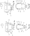
- the figure 1 represents a device 1 with strap 4 according to the invention designed to fix an electronic device 2, represented on the figure 2 , of the cell phone, camera, portable audio player, sensory sensor, gps plotter, etc. type, against the bust 3 of a user.
- the device 1 here comprises a strap 4 fixed to a band support 5 forming one and the same loop, which will be referred to here as a shoulder strap.
- the strap 4 is in the form of a strip of fabric or leather extending at two ends 4' and includes a system 7 for adjusting the length of the shoulder strap.
- the band support 5 comprises a first face 5', visible on the figure 1 , facing the side of the bust when the strap is worn over the shoulder and a second 5" side visible on the figure 2 opposite the first face 5'.
- This second face 5" notably comprises fixing means MF designed to fix the second face flat against the electronic device 2.
- the support 5 is a band extending between two ends respectively provided with anchor points 8 designed to be fixed respectively to the ends 4' of the strap 4.
- a self-adhesive strip can be provided, as shown in the figure 1 , made of a flexible material that is strong enough to resist tearing in the event of a snatching attempt.
- the means of fixing MF of the second face 5" represented on the figures 5a and 5b are here composed of a layer of adhesive material.
- the strip will preferably have a thickness of between 0.5 mm and 1 mm in order to be able to be inserted between the electronic device 2 and its protective shell, without however preventing the shell from closing.
- the strip can thus be stuck either against the internal surface of the shell or directly against the electronic device.
- the anchor points 8 of the strip are materialized by through holes 9 located at its ends, as shown in the figure 5a .
- the strip will for example have an elastic capacity allowing it to be stretched (or cut to the desired length) so as to present the holes outside the shell closed on the device.
- a protective shell, visible on the figure 6 , for electronic device 2 can be provided as support 5 instead of the strip.
- the anchor points 8 take the form, for example, of through holes 9 located on the outer edges of the shell, preferably lengthwise.
- the means of fixing the second face 5" materialize for their part by standard clips to fix the shell to the electronic device 2.
- the support 5, whether it is the strip or the shell, is able to be fixed with the strap 4 via connecting means 6, for example of the mechanical and/or magnetic type, as represented on the figures 5a and 5b .
- connection means 6 comprise for example carabiners 10 which are attached to the ends 4' of the strap 4 and/or to the anchor points 8 of the support 5.
- the carabiners 10 are here each provided with a magnet 11 designed to attract the magnet 11 which is arranged on the end of the strap 4 or of the opposite support 5.
- the device 1 can also comprise a strap 12, visible on the picture 2 , able to come connect two strap segments 4 with each other to strengthen the holding of the shoulder strap around the bust 3 of the user.
- the strap may also comprise at each of its ends an elastic return means 13 connecting the support.
- the return means 13 act as a safety device preventing the tearing of the support 5 from the device 1, but also tend to make the support 5 return in the direction of the ends of the strap so that the connecting means 6 fix again the strap 4 with the support 5, as shown in the figure 4a and 5b .
- the return means 13 in particular prohibit the spacing of the support 5 with respect to the strap 4 beyond a certain distance, preferably less than 50 cm, when the anchor points 8 and the ends 4' of the strap 4 are not fixed together, as shown on the figure 4b and 5a .
- the return means 13 are for example in the form of a cable reel 13' with elastic return, as shown in the figure 5a , or simply in the form of a rubber band or any other means allowing it to be deployed and retracted elastically.
- two return means 13 will be connected to the strap 4 and to the support 5, as visible on the figure 4b at the level of their respective ends.
- the strap comprises at each end 4' an elastic return means 13 connected to the support, here a winder 13', also called a winder/unwinder 13' with a return spring.
- the support strip 5 extends over a certain length and is fixed along its length by the connecting means 6 to carry the electronic device flat between the two ends 4' of the strap 4.
- the support strip 5 is also designed to be moved between a position of use in which the ends of the strap and the support are not fixed by the connecting means and a rest position, also called the closed position or initial position, wherein the ends of the strap and the support are fixed by the connecting means.
- the cables of the winder 13' are passed through the magnets 11 in order to create a cable path during the retraction of the cable 13' to connect the strap 4 and the support 5.
- the magnets 11 increase the holding force in the closed position of the connecting means 6.
- the support 5 may further comprise at least one third anchor point 8' not aligned with the two anchor points 8.
- an extendable or detachable cord 14 will have been provided via two magnets 14', visible on the figure 6 , to connect the strap 4 to the third anchor point 8 ', here on one end of the hull of a telephone in the width, so that the support 5 can be deployed in a position plate P.
- the support 5 is held substantially perpendicular to the strap 4 by the cord 13 which forms a bracket.
- the device 1 in order to facilitate the interactions between the electronic device 2 and its user, also comprises a connected assembly allowing remote access to the functionalities of the electronic device 2, in particular using the action fixing or separation of the support 5 with the strap 4.
- the connected shoulder strap assembly therefore comprises a sensor 15 designed to generate first data D1 indicating whether at least one of the two anchor points 8 of the support 5 is not fixed to one end of the strap 4, such as represented by the electrical diagram of the figure 3b and by device 1 of the figure 4b .
- the connected assembly further comprises a control command unit 16 capable of sending, in response to the first data D1, a first control signal S1 to the electronic device 2.
- the sensor 15 according to the invention is also designed to generate second data D2 indicating whether the two anchor points 8 of the support 5 are fixed to the ends of the strap 4, as represented by the electrical diagram of the picture 3a and by device 1 of the figure 4a .
- control command unit 16 is able sending, in response to the second data D2, a second control signal S2 to the electronic device 2 different from the first control signal S1.
- control signal is meant any type of digital signal making it possible, for example, to pick up or hang up a telephone call, to lock and unlock the electronic device 2, to increase or decrease the volume, to launch a digital application or even to turn off or turn on the electronic device 2.
- the connected assembly of the device 1 can include a loudspeaker 17, represented on the figures 4a and 4b .
- control command unit 16 is configured to, in response to the reception of the first data D1 from the sensor 15 and an audio signal AUDIO1 coming from the electronic device, to transmit the audio signal AUDIO1 to the loudspeaker 17.
- the connected assembly may also include a microphone 18, as shown in the figures 4a and 4b .
- control command unit 16 is configured to, in response to the reception of the first data D1 from the sensor 15 and an audio signal AUDIO2 coming from the microphone, to transmit the audio signal AUDIO2 to the electronic device.
- the connected assembly according to the invention may also include an LED 19 fixed to the strap and visible on the figures 4a and 4b , or any other means of sound, vibration, etc. indication, capable of transmitting a sensory indication IS1 to the user of the presence of any signal coming from the electronic device 2, for example a telephone call AP1 in waiting, as shown in the picture 3a .
- the LED 19 is here connected to the command control unit 16, as represented on the figures 3a and 3b , which controls its switching on or off in response to the incoming signal, here AP1, from the electronic device 2.
- the connected assembly according to the invention may also include a remote control 21 connected to the strap 4, which makes it possible to remotely control via the command control unit 16, the volume of the loudspeakers and of the microphone, as well as all the other functionalities described above.
- a battery 20 in strap 4 of device 1 to operate the connected assembly (sensor 15, command control unit 16, remote control, etc.) and electronic device 2.
- the user When using the device 1 according to the invention with a mobile phone, the user must first fix the phone via the support 5, for example using the strip.
- the LED 19 lights up, signifying that an incoming call is on hold, the user pulls the telephone attached to the strip in order to unhook the anchor points 8 at the ends 4' of the strap 4 from the connecting means 6.
- the command control unit 16 at this time sends a signal to the electronic device 2 to pick up the telephone call.
- the user repositions the support 5 in the initial position, that is to say where the anchor points 8 are connected to the ends 4' of the strap 4 by the connecting means 6 to hang up the telephone conversation.
Landscapes
- Purses, Travelling Bags, Baskets, Or Suitcases (AREA)
- Telephone Set Structure (AREA)
- Orthopedics, Nursing, And Contraception (AREA)
- Corsets Or Brassieres (AREA)
Claims (11)
- Vorrichtung (1) mit einem Gurt (4) zum Tragen mit Schulterriemen einer elektronischen Einrichtung (2) an der Brust (3) eines Benutzers, umfassend eine Bandhalterung (5), deren Band zum flachen Tragen der elektronischen Einrichtung sich über eine bestimmte Länge erstreckt, wobei die Vorrichtung Verbindungsmittel (6) umfasst, die zum Befestigen des Bands der Halterung in seiner Länge zwischen zwei Enden (4') des Gurts zum Ausbilden des Schulterriemens ausgelegt sind, wobei das Band der Bandhalterung eine erste Fläche (5'), die an der Seite der Brust ausgerichtet ist, wenn der Gurt mit Schulterriemen getragen wird, und eine zweite Fläche (5") gegenüber der ersten Fläche mit Befestigungsmitteln aufweist, die zum flachliegenden Befestigen der elektronischen Einrichtung an der zweiten Fläche des Bands der Halterung ausgelegt sind, dadurch gekennzeichnet, dass der Gurt an jedem Ende ein elastisches Rückstellmittel (13) umfasst, das mit der Halterung verbunden ist, wobei die Halterung zum Bewegtwerden zwischen einer Gebrauchsposition, in der die Enden des Gurts und die Halterung nicht durch die Verbindungsmittel befestigt sind, und einer Ruheposition ausgelegt ist, in der die Enden des Gurts und die Halterung durch die Verbindungsmittel befestigt sind, und dass die Rückstellmittel zum elastischen Zurückführen der Halterung von der Gebrauchsposition in die Ruheposition ausgelegt sind.
- Vorrichtung nach Anspruch 1, dadurch gekennzeichnet, dass die Halterung ein selbstklebendes Bändchen ist.
- Vorrichtung nach Anspruch 1, dadurch gekennzeichnet, dass die Halterung eine Schutzhülle für die elektronische Einrichtung ist.
- Vorrichtung nach einem der vorstehenden Ansprüche, dadurch gekennzeichnet, dass die Verbindungsmittel durch magnetische Anziehung funktionieren.
- Vorrichtung nach Anspruch 1, dadurch gekennzeichnet, dass die Rückstellmittel Auf-/Abwickler mit einer Rückstellfeder (13') sind.
- Vorrichtung nach Anspruch 1, dadurch gekennzeichnet, dass die Rückstellmittel elastische Seile sind.
- Vorrichtung nach einem der vorstehenden Ansprüche, dadurch gekennzeichnet, dass sie einen Sensor (15) umfasst, der zum Erzeugen erster Daten (D1) ausgelegt ist, die anzeigen, ob mindestens ein Ende des Gurts nicht mit der Halterung verbunden ist, und dass sie eine Befehlssteuereinheit (16) umfasst, die geeignet ist, um als Reaktion auf die ersten Daten ein erstes Befehlssignal (S1) an die elektronische Einrichtung zu senden.
- Vorrichtung nach Anspruch 7, dadurch gekennzeichnet, dass der Sensor zum Erzeugen zweiter Daten (D2) ausgelegt ist, die anzeigen, ob die zwei Enden des Gurts mit der Halterung verbunden sind, und dass die Befehlssteuereinheit geeignet ist, um als Reaktion auf diese zweiten Daten ein zweites Befehlssignal (S2) an die elektronische Einrichtung zu senden, das sich von dem ersten Befehlssignal unterscheidet.
- Vorrichtung nach Anspruch 7, dadurch gekennzeichnet, dass sie einen Lautsprecher (17) auf dem Gurt umfasst und dass die Befehlssteuereinheit zum, als Reaktion auf das Empfangen der ersten Daten von dem Sensor und eines Audiosignals (AUDIO1), das von der elektronischen Einrichtung stammt, Übertragen des Audiosignals an den Lautsprecher eingerichtet ist.
- Vorrichtung nach Anspruch 7, dadurch gekennzeichnet, dass sie ein Mikrophon (18) auf dem Gurt umfasst und dass die Befehlssteuereinheit zum, als Reaktion auf das Empfangen der ersten Daten des Sensors und eines Audiosignals (AUDIO2), das von dem Mikrofon stammt, Übertragen des Audiosignals an die elektronische Einrichtung eingerichtet ist.
- Vorrichtung nach einem der vorstehenden Ansprüche, dadurch gekennzeichnet, dass sie eine Schnur (14) umfasst, die den Gurt zum Ausbilden eines Winkels mit der Halterung verbindet, wobei die Halterung in einer Plattenposition (P) eingesetzt werden kann, in der sie durch die Schnur senkrecht zu dem Gurt erhalten wird.
Applications Claiming Priority (2)
| Application Number | Priority Date | Filing Date | Title |
|---|---|---|---|
| FR1857936A FR3085258B1 (fr) | 2018-09-04 | 2018-09-04 | Dispositif a sangle pour porter en bandouliere un appareil electronique contre le buste d'un utilisateur |
| PCT/FR2019/051981 WO2020049242A1 (fr) | 2018-09-04 | 2019-08-28 | Dispositif a sangle pour porter en bandouliere un appareil electronique contre le buste d'un utilisateur |
Publications (2)
| Publication Number | Publication Date |
|---|---|
| EP3846659A1 EP3846659A1 (de) | 2021-07-14 |
| EP3846659B1 true EP3846659B1 (de) | 2022-10-05 |
Family
ID=65201272
Family Applications (1)
| Application Number | Title | Priority Date | Filing Date |
|---|---|---|---|
| EP19774148.1A Active EP3846659B1 (de) | 2018-09-04 | 2019-08-28 | Vorrichtung mit riemen zum tragen eines elektronischen gerätes über die schulter gegen den brustkorb eines benutzers |
Country Status (3)
| Country | Link |
|---|---|
| EP (1) | EP3846659B1 (de) |
| FR (1) | FR3085258B1 (de) |
| WO (1) | WO2020049242A1 (de) |
Cited By (1)
| Publication number | Priority date | Publication date | Assignee | Title |
|---|---|---|---|---|
| US20210100329A1 (en) * | 2018-04-04 | 2021-04-08 | Todd Boss | Carry straps for electronic display devices |
Family Cites Families (4)
| Publication number | Priority date | Publication date | Assignee | Title |
|---|---|---|---|---|
| US8225973B1 (en) * | 2006-05-03 | 2012-07-24 | Bellinson Susan G | User-supported multiple pouch device |
| US20070278265A1 (en) * | 2006-05-30 | 2007-12-06 | Audrey Contente | System for carrying portable device |
| US20140103084A1 (en) | 2012-05-02 | 2014-04-17 | Daymen Us, Inc. | Pulley Camera Strap And Camera Mounting System Using Same |
| WO2017176922A1 (en) * | 2016-04-05 | 2017-10-12 | Tether Technologies, Inc. | Intelligent asset detachment sensor system |
-
2018
- 2018-09-04 FR FR1857936A patent/FR3085258B1/fr not_active Expired - Fee Related
-
2019
- 2019-08-28 EP EP19774148.1A patent/EP3846659B1/de active Active
- 2019-08-28 WO PCT/FR2019/051981 patent/WO2020049242A1/fr not_active Ceased
Cited By (2)
| Publication number | Priority date | Publication date | Assignee | Title |
|---|---|---|---|---|
| US20210100329A1 (en) * | 2018-04-04 | 2021-04-08 | Todd Boss | Carry straps for electronic display devices |
| US11877635B2 (en) * | 2018-04-04 | 2024-01-23 | Todd Boss | Carry straps for electronic display devices |
Also Published As
| Publication number | Publication date |
|---|---|
| WO2020049242A1 (fr) | 2020-03-12 |
| FR3085258B1 (fr) | 2021-12-03 |
| FR3085258A1 (fr) | 2020-03-06 |
| EP3846659A1 (de) | 2021-07-14 |
Similar Documents
| Publication | Publication Date | Title |
|---|---|---|
| US6502727B1 (en) | Device and method for holding a handheld object | |
| EP0469503B1 (de) | Aufnahmevorrichtung für eine Speicherkarte | |
| US9496911B2 (en) | Protective cover and retractable lanyard | |
| US9389487B2 (en) | Protective lens attachment | |
| FR2910862A1 (fr) | Attache universelle pour tout type d'applications et de systemes dont un ecran ou un appareil de navigation y compris par telephone mobile a un retroviseur interieur. | |
| FR3040252A1 (de) | ||
| EP3846659B1 (de) | Vorrichtung mit riemen zum tragen eines elektronischen gerätes über die schulter gegen den brustkorb eines benutzers | |
| EP3001696A2 (de) | Kontaktloses wiederaufladbares audio-headset | |
| KR101851292B1 (ko) | 고리가 일체로 구비된 스마트 디바이스용 카드 케이스 | |
| KR101461004B1 (ko) | 측면터치가 가능한 스마트폰 케이스 | |
| KR200463097Y1 (ko) | 릴타입 이어폰이 부착된 휴대용 단말기 케이스 및 탈부착이 가능한 릴타입 이어폰 | |
| KR20160018306A (ko) | 휴대 전자기기용 커버 | |
| US8422208B2 (en) | Stand fixing mechanism and electronic device using the same | |
| US20180177284A1 (en) | Phone carrier | |
| EP3860381B1 (de) | Helm mit einem ring zum verbinden des helmes mit einem diebstahlschutzsystem | |
| FR2510367A1 (fr) | Dispositif anti-vol pour sac ou bagage a main | |
| FR2527813A1 (fr) | Dispositif d'alarme contre le vol a la tire | |
| KR101463606B1 (ko) | 휴대폰 케이스 | |
| FR3024343A1 (fr) | Systeme de protection pour dispositif de communication mobile et procede d'installation de ce systeme de protection | |
| US9000922B1 (en) | Honesty test system | |
| FR3049835A1 (fr) | Systeme de fixation d'un accessoire pour appareil electronique portable, et accessoire dote d'un tel systeme | |
| WO2011135251A1 (fr) | Support de fixation d'appareil électronique portatif, et planche de bord et véhicule automobile équipés d'un tel support | |
| KR20210089516A (ko) | 클립형 몰카 탐지기 | |
| US11975579B1 (en) | Boat securement alerting apparatus | |
| US20250134195A1 (en) | Self-defense glove |
Legal Events
| Date | Code | Title | Description |
|---|---|---|---|
| STAA | Information on the status of an ep patent application or granted ep patent |
Free format text: STATUS: UNKNOWN |
|
| STAA | Information on the status of an ep patent application or granted ep patent |
Free format text: STATUS: THE INTERNATIONAL PUBLICATION HAS BEEN MADE |
|
| PUAI | Public reference made under article 153(3) epc to a published international application that has entered the european phase |
Free format text: ORIGINAL CODE: 0009012 |
|
| STAA | Information on the status of an ep patent application or granted ep patent |
Free format text: STATUS: REQUEST FOR EXAMINATION WAS MADE |
|
| 17P | Request for examination filed |
Effective date: 20210406 |
|
| AK | Designated contracting states |
Kind code of ref document: A1 Designated state(s): AL AT BE BG CH CY CZ DE DK EE ES FI FR GB GR HR HU IE IS IT LI LT LU LV MC MK MT NL NO PL PT RO RS SE SI SK SM TR |
|
| DAV | Request for validation of the european patent (deleted) | ||
| DAX | Request for extension of the european patent (deleted) | ||
| GRAP | Despatch of communication of intention to grant a patent |
Free format text: ORIGINAL CODE: EPIDOSNIGR1 |
|
| STAA | Information on the status of an ep patent application or granted ep patent |
Free format text: STATUS: GRANT OF PATENT IS INTENDED |
|
| INTG | Intention to grant announced |
Effective date: 20220623 |
|
| GRAS | Grant fee paid |
Free format text: ORIGINAL CODE: EPIDOSNIGR3 |
|
| GRAA | (expected) grant |
Free format text: ORIGINAL CODE: 0009210 |
|
| STAA | Information on the status of an ep patent application or granted ep patent |
Free format text: STATUS: THE PATENT HAS BEEN GRANTED |
|
| AK | Designated contracting states |
Kind code of ref document: B1 Designated state(s): AL AT BE BG CH CY CZ DE DK EE ES FI FR GB GR HR HU IE IS IT LI LT LU LV MC MK MT NL NO PL PT RO RS SE SI SK SM TR |
|
| REG | Reference to a national code |
Ref country code: GB Ref legal event code: FG4D Free format text: NOT ENGLISH |
|
| REG | Reference to a national code |
Ref country code: CH Ref legal event code: EP |
|
| REG | Reference to a national code |
Ref country code: AT Ref legal event code: REF Ref document number: 1522211 Country of ref document: AT Kind code of ref document: T Effective date: 20221015 |
|
| REG | Reference to a national code |
Ref country code: DE Ref legal event code: R096 Ref document number: 602019020331 Country of ref document: DE |
|
| REG | Reference to a national code |
Ref country code: IE Ref legal event code: FG4D Free format text: LANGUAGE OF EP DOCUMENT: FRENCH |
|
| REG | Reference to a national code |
Ref country code: LT Ref legal event code: MG9D |
|
| REG | Reference to a national code |
Ref country code: NL Ref legal event code: MP Effective date: 20221005 |
|
| REG | Reference to a national code |
Ref country code: AT Ref legal event code: MK05 Ref document number: 1522211 Country of ref document: AT Kind code of ref document: T Effective date: 20221005 |
|
| PG25 | Lapsed in a contracting state [announced via postgrant information from national office to epo] |
Ref country code: NL Free format text: LAPSE BECAUSE OF FAILURE TO SUBMIT A TRANSLATION OF THE DESCRIPTION OR TO PAY THE FEE WITHIN THE PRESCRIBED TIME-LIMIT Effective date: 20221005 |
|
| PG25 | Lapsed in a contracting state [announced via postgrant information from national office to epo] |
Ref country code: SE Free format text: LAPSE BECAUSE OF FAILURE TO SUBMIT A TRANSLATION OF THE DESCRIPTION OR TO PAY THE FEE WITHIN THE PRESCRIBED TIME-LIMIT Effective date: 20221005 Ref country code: PT Free format text: LAPSE BECAUSE OF FAILURE TO SUBMIT A TRANSLATION OF THE DESCRIPTION OR TO PAY THE FEE WITHIN THE PRESCRIBED TIME-LIMIT Effective date: 20230206 Ref country code: NO Free format text: LAPSE BECAUSE OF FAILURE TO SUBMIT A TRANSLATION OF THE DESCRIPTION OR TO PAY THE FEE WITHIN THE PRESCRIBED TIME-LIMIT Effective date: 20230105 Ref country code: LT Free format text: LAPSE BECAUSE OF FAILURE TO SUBMIT A TRANSLATION OF THE DESCRIPTION OR TO PAY THE FEE WITHIN THE PRESCRIBED TIME-LIMIT Effective date: 20221005 Ref country code: FI Free format text: LAPSE BECAUSE OF FAILURE TO SUBMIT A TRANSLATION OF THE DESCRIPTION OR TO PAY THE FEE WITHIN THE PRESCRIBED TIME-LIMIT Effective date: 20221005 Ref country code: ES Free format text: LAPSE BECAUSE OF FAILURE TO SUBMIT A TRANSLATION OF THE DESCRIPTION OR TO PAY THE FEE WITHIN THE PRESCRIBED TIME-LIMIT Effective date: 20221005 Ref country code: AT Free format text: LAPSE BECAUSE OF FAILURE TO SUBMIT A TRANSLATION OF THE DESCRIPTION OR TO PAY THE FEE WITHIN THE PRESCRIBED TIME-LIMIT Effective date: 20221005 |
|
| PG25 | Lapsed in a contracting state [announced via postgrant information from national office to epo] |
Ref country code: RS Free format text: LAPSE BECAUSE OF FAILURE TO SUBMIT A TRANSLATION OF THE DESCRIPTION OR TO PAY THE FEE WITHIN THE PRESCRIBED TIME-LIMIT Effective date: 20221005 Ref country code: PL Free format text: LAPSE BECAUSE OF FAILURE TO SUBMIT A TRANSLATION OF THE DESCRIPTION OR TO PAY THE FEE WITHIN THE PRESCRIBED TIME-LIMIT Effective date: 20221005 Ref country code: LV Free format text: LAPSE BECAUSE OF FAILURE TO SUBMIT A TRANSLATION OF THE DESCRIPTION OR TO PAY THE FEE WITHIN THE PRESCRIBED TIME-LIMIT Effective date: 20221005 Ref country code: IS Free format text: LAPSE BECAUSE OF FAILURE TO SUBMIT A TRANSLATION OF THE DESCRIPTION OR TO PAY THE FEE WITHIN THE PRESCRIBED TIME-LIMIT Effective date: 20230205 Ref country code: HR Free format text: LAPSE BECAUSE OF FAILURE TO SUBMIT A TRANSLATION OF THE DESCRIPTION OR TO PAY THE FEE WITHIN THE PRESCRIBED TIME-LIMIT Effective date: 20221005 Ref country code: GR Free format text: LAPSE BECAUSE OF FAILURE TO SUBMIT A TRANSLATION OF THE DESCRIPTION OR TO PAY THE FEE WITHIN THE PRESCRIBED TIME-LIMIT Effective date: 20230106 |
|
| REG | Reference to a national code |
Ref country code: DE Ref legal event code: R097 Ref document number: 602019020331 Country of ref document: DE |
|
| PG25 | Lapsed in a contracting state [announced via postgrant information from national office to epo] |
Ref country code: SM Free format text: LAPSE BECAUSE OF FAILURE TO SUBMIT A TRANSLATION OF THE DESCRIPTION OR TO PAY THE FEE WITHIN THE PRESCRIBED TIME-LIMIT Effective date: 20221005 Ref country code: RO Free format text: LAPSE BECAUSE OF FAILURE TO SUBMIT A TRANSLATION OF THE DESCRIPTION OR TO PAY THE FEE WITHIN THE PRESCRIBED TIME-LIMIT Effective date: 20221005 Ref country code: EE Free format text: LAPSE BECAUSE OF FAILURE TO SUBMIT A TRANSLATION OF THE DESCRIPTION OR TO PAY THE FEE WITHIN THE PRESCRIBED TIME-LIMIT Effective date: 20221005 Ref country code: DK Free format text: LAPSE BECAUSE OF FAILURE TO SUBMIT A TRANSLATION OF THE DESCRIPTION OR TO PAY THE FEE WITHIN THE PRESCRIBED TIME-LIMIT Effective date: 20221005 Ref country code: CZ Free format text: LAPSE BECAUSE OF FAILURE TO SUBMIT A TRANSLATION OF THE DESCRIPTION OR TO PAY THE FEE WITHIN THE PRESCRIBED TIME-LIMIT Effective date: 20221005 |
|
| PLBE | No opposition filed within time limit |
Free format text: ORIGINAL CODE: 0009261 |
|
| STAA | Information on the status of an ep patent application or granted ep patent |
Free format text: STATUS: NO OPPOSITION FILED WITHIN TIME LIMIT |
|
| PG25 | Lapsed in a contracting state [announced via postgrant information from national office to epo] |
Ref country code: SK Free format text: LAPSE BECAUSE OF FAILURE TO SUBMIT A TRANSLATION OF THE DESCRIPTION OR TO PAY THE FEE WITHIN THE PRESCRIBED TIME-LIMIT Effective date: 20221005 Ref country code: AL Free format text: LAPSE BECAUSE OF FAILURE TO SUBMIT A TRANSLATION OF THE DESCRIPTION OR TO PAY THE FEE WITHIN THE PRESCRIBED TIME-LIMIT Effective date: 20221005 |
|
| 26N | No opposition filed |
Effective date: 20230706 |
|
| PGFP | Annual fee paid to national office [announced via postgrant information from national office to epo] |
Ref country code: GB Payment date: 20230822 Year of fee payment: 5 |
|
| PG25 | Lapsed in a contracting state [announced via postgrant information from national office to epo] |
Ref country code: SI Free format text: LAPSE BECAUSE OF FAILURE TO SUBMIT A TRANSLATION OF THE DESCRIPTION OR TO PAY THE FEE WITHIN THE PRESCRIBED TIME-LIMIT Effective date: 20221005 |
|
| PGFP | Annual fee paid to national office [announced via postgrant information from national office to epo] |
Ref country code: FR Payment date: 20230828 Year of fee payment: 5 Ref country code: DE Payment date: 20230821 Year of fee payment: 5 |
|
| PG25 | Lapsed in a contracting state [announced via postgrant information from national office to epo] |
Ref country code: MC Free format text: LAPSE BECAUSE OF FAILURE TO SUBMIT A TRANSLATION OF THE DESCRIPTION OR TO PAY THE FEE WITHIN THE PRESCRIBED TIME-LIMIT Effective date: 20221005 |
|
| REG | Reference to a national code |
Ref country code: CH Ref legal event code: PL |
|
| PG25 | Lapsed in a contracting state [announced via postgrant information from national office to epo] |
Ref country code: MC Free format text: LAPSE BECAUSE OF FAILURE TO SUBMIT A TRANSLATION OF THE DESCRIPTION OR TO PAY THE FEE WITHIN THE PRESCRIBED TIME-LIMIT Effective date: 20221005 |
|
| PG25 | Lapsed in a contracting state [announced via postgrant information from national office to epo] |
Ref country code: LU Free format text: LAPSE BECAUSE OF NON-PAYMENT OF DUE FEES Effective date: 20230828 |
|
| PG25 | Lapsed in a contracting state [announced via postgrant information from national office to epo] |
Ref country code: LU Free format text: LAPSE BECAUSE OF NON-PAYMENT OF DUE FEES Effective date: 20230828 Ref country code: CH Free format text: LAPSE BECAUSE OF NON-PAYMENT OF DUE FEES Effective date: 20230831 |
|
| REG | Reference to a national code |
Ref country code: BE Ref legal event code: MM Effective date: 20230831 |
|
| REG | Reference to a national code |
Ref country code: IE Ref legal event code: MM4A |
|
| PG25 | Lapsed in a contracting state [announced via postgrant information from national office to epo] |
Ref country code: IT Free format text: LAPSE BECAUSE OF FAILURE TO SUBMIT A TRANSLATION OF THE DESCRIPTION OR TO PAY THE FEE WITHIN THE PRESCRIBED TIME-LIMIT Effective date: 20221005 |
|
| PG25 | Lapsed in a contracting state [announced via postgrant information from national office to epo] |
Ref country code: IE Free format text: LAPSE BECAUSE OF NON-PAYMENT OF DUE FEES Effective date: 20230828 |
|
| PG25 | Lapsed in a contracting state [announced via postgrant information from national office to epo] |
Ref country code: IE Free format text: LAPSE BECAUSE OF NON-PAYMENT OF DUE FEES Effective date: 20230828 |
|
| PG25 | Lapsed in a contracting state [announced via postgrant information from national office to epo] |
Ref country code: BE Free format text: LAPSE BECAUSE OF NON-PAYMENT OF DUE FEES Effective date: 20230831 |
|
| PG25 | Lapsed in a contracting state [announced via postgrant information from national office to epo] |
Ref country code: BG Free format text: LAPSE BECAUSE OF FAILURE TO SUBMIT A TRANSLATION OF THE DESCRIPTION OR TO PAY THE FEE WITHIN THE PRESCRIBED TIME-LIMIT Effective date: 20221005 |
|
| PG25 | Lapsed in a contracting state [announced via postgrant information from national office to epo] |
Ref country code: BG Free format text: LAPSE BECAUSE OF FAILURE TO SUBMIT A TRANSLATION OF THE DESCRIPTION OR TO PAY THE FEE WITHIN THE PRESCRIBED TIME-LIMIT Effective date: 20221005 |
|
| REG | Reference to a national code |
Ref country code: DE Ref legal event code: R119 Ref document number: 602019020331 Country of ref document: DE |
|
| GBPC | Gb: european patent ceased through non-payment of renewal fee |
Effective date: 20240828 |
|
| PG25 | Lapsed in a contracting state [announced via postgrant information from national office to epo] |
Ref country code: DE Free format text: LAPSE BECAUSE OF NON-PAYMENT OF DUE FEES Effective date: 20250301 |
|
| PG25 | Lapsed in a contracting state [announced via postgrant information from national office to epo] |
Ref country code: GB Free format text: LAPSE BECAUSE OF NON-PAYMENT OF DUE FEES Effective date: 20240828 |
|
| PG25 | Lapsed in a contracting state [announced via postgrant information from national office to epo] |
Ref country code: FR Free format text: LAPSE BECAUSE OF NON-PAYMENT OF DUE FEES Effective date: 20240831 |
|
| PG25 | Lapsed in a contracting state [announced via postgrant information from national office to epo] |
Ref country code: CY Free format text: LAPSE BECAUSE OF FAILURE TO SUBMIT A TRANSLATION OF THE DESCRIPTION OR TO PAY THE FEE WITHIN THE PRESCRIBED TIME-LIMIT; INVALID AB INITIO Effective date: 20190828 |
|
| PG25 | Lapsed in a contracting state [announced via postgrant information from national office to epo] |
Ref country code: HU Free format text: LAPSE BECAUSE OF FAILURE TO SUBMIT A TRANSLATION OF THE DESCRIPTION OR TO PAY THE FEE WITHIN THE PRESCRIBED TIME-LIMIT; INVALID AB INITIO Effective date: 20190828 |
|
| PG25 | Lapsed in a contracting state [announced via postgrant information from national office to epo] |
Ref country code: TR Free format text: LAPSE BECAUSE OF FAILURE TO SUBMIT A TRANSLATION OF THE DESCRIPTION OR TO PAY THE FEE WITHIN THE PRESCRIBED TIME-LIMIT Effective date: 20221005 |