EP3846670B1 - Türverriegelungsvorrichtung für ein elektrisches haushaltsgerät, insbesondere eine spülmaschine, und elektrisches haushaltsgerät damit - Google Patents
Türverriegelungsvorrichtung für ein elektrisches haushaltsgerät, insbesondere eine spülmaschine, und elektrisches haushaltsgerät damit Download PDFInfo
- Publication number
- EP3846670B1 EP3846670B1 EP19762895.1A EP19762895A EP3846670B1 EP 3846670 B1 EP3846670 B1 EP 3846670B1 EP 19762895 A EP19762895 A EP 19762895A EP 3846670 B1 EP3846670 B1 EP 3846670B1
- Authority
- EP
- European Patent Office
- Prior art keywords
- door
- support body
- blocking tooth
- mobile element
- lever
- Prior art date
- Legal status (The legal status is an assumption and is not a legal conclusion. Google has not performed a legal analysis and makes no representation as to the accuracy of the status listed.)
- Active
Links
Images





Classifications
-
- E—FIXED CONSTRUCTIONS
- E05—LOCKS; KEYS; WINDOW OR DOOR FITTINGS; SAFES
- E05B—LOCKS; ACCESSORIES THEREFOR; HANDCUFFS
- E05B63/00—Locks or fastenings with special structural characteristics
- E05B63/22—Locks or fastenings with special structural characteristics operated by a pulling or pushing action perpendicular to the front plate, i.e. by pulling or pushing the wing itself
-
- A—HUMAN NECESSITIES
- A47—FURNITURE; DOMESTIC ARTICLES OR APPLIANCES; COFFEE MILLS; SPICE MILLS; SUCTION CLEANERS IN GENERAL
- A47L—DOMESTIC WASHING OR CLEANING; SUCTION CLEANERS IN GENERAL
- A47L15/00—Washing or rinsing machines for crockery or tableware
- A47L15/42—Details
- A47L15/4251—Details of the casing
- A47L15/4257—Details of the loading door
- A47L15/4259—Arrangements of locking or security/safety devices for doors, e.g. door latches, switch to stop operation when door is open
-
- E—FIXED CONSTRUCTIONS
- E05—LOCKS; KEYS; WINDOW OR DOOR FITTINGS; SAFES
- E05B—LOCKS; ACCESSORIES THEREFOR; HANDCUFFS
- E05B47/00—Operating or controlling locks or other fastening devices by electric or magnetic means
- E05B47/0001—Operating or controlling locks or other fastening devices by electric or magnetic means with electric actuators; Constructional features thereof
-
- E—FIXED CONSTRUCTIONS
- E05—LOCKS; KEYS; WINDOW OR DOOR FITTINGS; SAFES
- E05C—BOLTS OR FASTENING DEVICES FOR WINGS, SPECIALLY FOR DOORS OR WINDOWS
- E05C5/00—Fastening devices with bolts moving otherwise than only rectilinearly and only pivotally or rotatively
-
- E—FIXED CONSTRUCTIONS
- E05—LOCKS; KEYS; WINDOW OR DOOR FITTINGS; SAFES
- E05F—DEVICES FOR MOVING WINGS INTO OPEN OR CLOSED POSITION; CHECKS FOR WINGS; WING FITTINGS NOT OTHERWISE PROVIDED FOR, CONCERNED WITH THE FUNCTIONING OF THE WING
- E05F15/00—Power-operated mechanisms for wings
- E05F15/60—Power-operated mechanisms for wings using electrical actuators
-
- E—FIXED CONSTRUCTIONS
- E05—LOCKS; KEYS; WINDOW OR DOOR FITTINGS; SAFES
- E05Y—INDEXING SCHEME ASSOCIATED WITH SUBCLASSES E05D AND E05F, RELATING TO CONSTRUCTION ELEMENTS, ELECTRIC CONTROL, POWER SUPPLY, POWER SIGNAL OR TRANSMISSION, USER INTERFACES, MOUNTING OR COUPLING, DETAILS, ACCESSORIES, AUXILIARY OPERATIONS NOT OTHERWISE PROVIDED FOR, APPLICATION THEREOF
- E05Y2900/00—Application of doors, windows, wings or fittings thereof
- E05Y2900/30—Application of doors, windows, wings or fittings thereof for domestic appliances
- E05Y2900/304—Application of doors, windows, wings or fittings thereof for domestic appliances for dishwashers
Definitions
- the present invention relates to a door lock device for a household appliance such as a dishwasher machine, as well as the household appliance equipped with such a door lock device.
- EP1344486 an door lock device of great simplicity and reduced footprint based on a rotating deadlock connected to a bistable elastic mechanism which causes the deadlock to assume selectively two different stable positions, respectively involving a locking position, in which the deadlock engages with a hook element when the door is closed, usually consisting of a U-shaped bracket, and an unlocking position, in which the deadlock does not engage with the hook element.
- WO 2014/061044 A2 discloses a door-look device for a household appliance having several features in common with the device of claim 1.
- the known door lock devices are not for the most part adapted to allow the opening of the door with a "push to open" type device, for example, by using a motorized pushing device such as the one produced by EBE GmbH and known under the brand of "Magical doorway of dishwashers".
- One purpose of the present invention is to provide a door lock device for a household appliance, in particular a dishwasher, which is simple in design, has a reduced cost and footprint and good reliability, and which makes it possible to design household appliances with thin doors.
- Another purpose of the invention is to provide a door lock device having the ability to be used, for example with the addition of a simple accessory, with motorized door opening devices of the "push to open" type, in order to design household appliances without external handles, currently greatly desired by kitchen designers.
- the present invention thus relates to a door lock device for a household appliance, in particular a dishwasher, and to a household appliance equipped with such a door lock device, as defined in the enclosed claims.
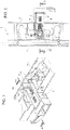
- a door lock device for a household appliance 2 in particular a dishwasher, of which household appliance there is illustrated for simplicity only part of a structural element 3, in the present instance an upper front cross piece of a housing of the household appliance bounded by an upper edge of an access compartment to a washing chamber or tub 4 bounded off by the housing and closed during use by a closure door 5 of the access compartment.
- the door lock device according to the invention may be applied either to doors with horizontal axis of rotation or doors with vertical access of rotation. Therefore, the invention may also be used for drawer dishwashing machines.
- the door lock device 1 comprises a support body 6 designed to be attached during use, in known manner and not illustrated for reasons of simplicity, to the structural element 3 of the household appliance 1.
- the structural element 3 is further designed to receive the door 5 in abutment across an intermediate perimeter gasket 7 mounted on the rim of the tub (not shown in the drawings) beneath the structural element 3, composed of an upper cross bar of the dishwasher ( Figure 3 ), which is known and illustrated only schematically for simplicity.
- the door lock device 1 further comprises a movable deadlock 8 carried by the support body 6 and designed to cooperate in use with a receiving compartment or seat 9, known in itself and devised on the perimeter of the door 5, in the example illustrated within an upper rim of same.
- the movable deadlock 8 comprises a locking tooth 10 carried by the support body 6 and, according to one aspect of the invention, connected to the support body 6 in such a way that it can both translate and rotate relative to the support body 6 along a predetermined trajectory.
- the locking tooth 10 has a first end 11 designed as a hook and configured to be coupled in known manner with the receiving compartment or seat 9 of the door 5 to lock the door 5 against the structural element 3 of the household appliance 1 with the gasket 7 interposed in between.
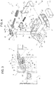
- the movable deadlock 8 further comprises a rod 12 carried in axially sliding manner (with respect to its own axis of symmetry A - Figure 4 ) by the support body 6 and connected by means of an articulated device 13 (which shall be further described below) to a second end 14 of the locking tooth 10, opposite the first end 11.
- the movable deadlock 8 further comprises, according to one aspect of the invention, first elastic compression means 15 operatively associated with the rod 12 and configured to push the rod 12 toward the locking tooth 10 relatively to the support body 6.
- the first elastic compression means 15 are comprised of a helical spring seated coaxially on the rod 12 and inserted as a pack, preloaded, between a shoulder surface 16 of the support body 6 ( Figures 5 and 6 ) and an axial stop shoulder 17 integrated with the rod 12, on the part with the locking tooth 10 and in the present instance comprised of an annular flange ( Figure 4 ) produced as a single piece with the rod 12.
- the movable deadlock 8 finally comprises, according to the invention, a control device or actuator 18 comprising a movable element 19 carried by the support body 6 and designed to cooperate during use with the door 5 in order to selectively assume a first working position with the door open, illustrated schematically in Figure 3 , and a second operating position with the door closed, illustrated schematically in Figure 6 .
- the movable element 19 is operatively associated, in the manner which shall be illustrated, with the locking tooth 10 to make it assume selectively a first and a second operating position, (illustrated in Figures 3 and 6 ), corresponding to said first and second working position of the movable element 19 respectively.
- the first end 11 of the locking tooth 10 is adapted to not cooperate with the receiving compartment or seat 9, being almost entirely retracted within the support body 6 and therefore situated at a distance, in the present instance, above the upper rim of the door 5 provided with the receiving seat 9.
- the articulated device 13 consists simply of a pin 21 and one end 22 of the rod 12 ( Figure 4 ), preferably shaped as a hook, which end 22 is adjacent to the axial stop shoulder 17 and is connected in a hinge, by means of the pin 21, directly to the second end 14 of the locking tooth 10.
- the first elastic compression means 15 are designed to push the locking tooth 10, acting on it through the rod 12, toward the second operating position.
- the movable element 19 consists of a sled carried in sliding manner by the support body 6 contrary to the action of second elastic compression means 23, adapted to push the movable element 19 against the locking tooth 10 so as to maintain the latter normally, against the action of the first elastic compression means 15, in said first operating position.
- the elastic means 23 consist of a helical spring installed, preloaded, in a pack between the shoulder surface 16, beneath the spring 15, and a cup-shaped seat 24 devised in the movable element or sled 19.
- Figures 3 , 5 and 6 only illustrate schematically the various positions which may be assumed during use by the movable deadlock 8; in particular, in Figure 3 the spring 15 is represented in a nondeformed configuration, so that it continues beyond the shoulder surface 16, while in Figure 5 , also illustrated on enlarged scale, the spring 15 is shown deformed (compressed) in the preloading position, properly abutting against the shoulder surface 16.
- the locking tooth 10 finds itself with its first end 11 arranged in a position retracted inside the support body 6, while in the second operating position the locking tooth 10 finds itself with its first end 11 completely extracted from the support body 6 and protruding as a cantilever from the latter through a continuous opening 25 of the support body 6.
- the sled (or movable element) 19 is designed as a frame and cooperates directly in contact with an intermediate portion 26 of the locking tooth 10 ( Figures 3 to 5 ), arranged between the ends 11 and 14 of same, by a pair of inclined planes 27 carried by opposite lateral flanks 28 ( Figure 4 ) of the sled 19.
- the inclined planes 27 are oriented in such a way as to cause a progressive movement of the first end 11 of the locking tooth 10, through the continuous opening 25 and toward the second operating position, under the thrusting of the first elastic compression means 15, as a result of a sliding movement of the sled 19 contrary to the action of the second elastic compression means 23 and in such a direction as to bring the sled 19 closer to the shoulder surface 16.
- the locking tooth 10 is connected to the support body 6 by means of a pair of lateral pins 29 ( Figure 4 ) which protrude cantilevered from both opposite longitudinal flanks 30 (of which only one is visible in Figure 4 ) of the locking tooth 10.
- the pins 29 engage respective cams 31 of the support body 6 adapted to guide the locking tooth 10 along said predetermined trajectory.
- the support body 6 is designed as a frame and is provided at its opposite lateral longitudinal members 32 with respective slots and/or grooves forming said cams 31.
- Each slot and/or groove 31 comprises a first straight branch 33, oriented perpendicular to a sliding direction D ( Figure 4 ) of the movable element 19 relatively to the support body 6.
- a first end 34 of the first branch 33 extends up to and interrupting or passing through a rim 35 of the lateral longitudinal members 32.
- the rim 35 is situated opposite a fin 36 of the movable element or sliding sled 19 which is designed to protrude cantilevered from the support body 6, for example through the continuous opening 25 or another similar continuous opening devised through the support body 6.
- the rim 36 is adapted to cooperate during use in contact with the door 5 of the household appliance 1, when the door is displaced toward a closing position, illustrated in Figure 6 ; for example, the fin 36 begins to cooperate with the door 5 when the door, moving in the direction of the arrow, reaches a partial closed position ( Figure 5 ), in which it is ajar from the access compartment bounding the washing chamber or tub 4 and from the gasket 7.
- the grooves and/or slots 31 further comprise: a second substantially straight branch 37, oriented perpendicular to the first branch 33, with which it communicates, and turned toward the rod 12; and a recess 38 devised laterally to the first branch 33, on the side opposite the second branch 37 and offset relative to the latter toward a second end 40 of the first branch 33, opposite the first end 24.
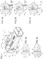
- the recess 38 is communicating with the first branch 33 and is able to receive at least partly one of the pins 29 ( Figures 8a and 9a ).
- the grooves and/or slots 31 finally comprise: respective inclined planes 41 ( Figures 8 and 9 ) which connect, respectively, the second branch 37 to the first branch 33 and the recess 38 to a portion of the first branch 33 comprised between the second branch 37 and the first end 34 of the first branch 33.
- the movable deadlock 8 finds itself in the configuration schematically illustrated in Figure 3 : the spring 23 maintains the sled 19 at the end of its travel, abutting against the locking tooth 10 so that the spring 15 cannot force the locking tooth 10 to rotate into a position extracted from the support body 6.
- the locking of the tooth 10 is also assisted by the pins 29, which engage the cams 31 in the configuration of Figure 8c , in which the pin 29 engaging the branch 33 cannot move toward the end 40 because of the presence of the inclined planes 27.
- the fin 36 intercepts the door 5 (in the present instance, the fin 36 intercepts the upper rim of the door 5 provided with the receiving compartment or seat 9); the door 5 is then able to continue its closing movement in the direction of the arrow and cause the sled 19 to be translated against the action of the spring 23 toward the shoulder surface 16.
- the pin 29 closer to the end 14 jumps over the branch 33 and positions itself in the recess 38, while the pin 29 closer to the end 11 is taken to the end of its travel, abutting against the end 40.
- the recess 38 and the width of the branch 33 are configured such that, in the position of Figure 6 , the spring 15 thanks to its preloading forces the tooth 10 to push by its end 11 the door 5 against the gasket 7, ensuring a liquid-tight closure of the door 5. Moreover, this makes it possible to ensure the useful travel C for the end 11 of the tooth 10 ( Figure 8b ).
- the above described conformation of the cams 31 also allows, when the door 5 is closed and locked, a subsequent manual pushing of the door 5 against the gasket 7, since the pin 29 closer to the end 14, thanks to the inclined plane 41 arranged between the recess 38 and the end 34 of the frame 33, can move slightly to fit into the end 34 yet still remain in contact with the inclined plane 41, while the pin 29 closer to the end 11 rises up slightly in the branch 33, moving away from its contact with the end 40.
- the vertical movement is utilized especially as a reset function in the event that, by accident or at will, the device is turned on in the "closed" position, i.e., without the door being present.
- the end 11 fig. 8a
- the door passes beyond the end 11 to reach the seat 9. In this condition, the mechanism is reset and the door will be closed.
- the door lock device 1 finally is optionally endowed with an accessory 42 for opening the door 5 of the "push to open” type, making it possible to design household appliances 1 without handles.
- This accessory 42 consists of a squared lever 43 carried in sliding manner by the support body 6 parallel to the direction D and an electromechanical module 44, known in itself ( Figure 4 ).
- the squared lever 43 comprises a first end 45 shaped as a fin and protruding cantilevered from the support body 6, disposed adjacent to the fin 36.
- the end 45 is adapted to cooperate by contact with the door 5 starting from an immediate proximity to a closed door 5 position and for the additional travel allowed by the configuration described for the cams 31.
- the user by pushing the door 5 when the door 5 is closed and locked displaces the end 45 and moves the squared lever 43.
- This lever comprises a second fin-shaped end 46, oriented perpendicular to the first end 45 and movably lodged inside a seat 47, also containing the electromechanical module 44.
- the door 5 is consequently forced by the electromechanical module 44 to move toward the open door 5 position as illustrated in Figure 3 .
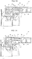
- FIGS 10 to 14 illustrate a door lock device 1b representing a different embodiment of the door lock device according to the invention. Details similar or identical to those already described are given the same reference numbers, for simplicity.
- the device 1b differs from the device 1 already described solely by the different realization of the articulated device 13 and the movable element 19.
- the movable element or activator consists of a frame of U shape 49 comprising two longitudinal members 50, which are joined together by a cross piece 51 at a first end 52 of the movable element 49.
- the longitudinal members 50 are provided, at a second end 53 of the movable element 49, opposite the first end, with respective fins 54 (only one being visible in Figure 10 ) adapted to cooperate in use by contact with the door 5 of the household appliance 1.
- the fins 54 protrude cantilevered from the support body 6 through an opening 25 passing through the support body 6, similar to the fin 36 of the device 1.
- the movable element defined by the frame 49 is in this case adapted to rotate, rather than be translated.
- the frame 49 is hinged to the support body 6 by means of a first pin 56 passing through in the area of its first end 52 of the frame 49.
- the fins 54 are provided, on the portion with said second end 53 of the frame 49, with respective inclined planes 57 adapted to cause a relative rotation between the movable element 49 and the support body 6 in such a direction as to progressively move the fins 54 into a retracted position relative to the support body 6 as a result of a thrusting applied to said inclined planes 57, in a use dictated by the progressive closing of the door 5 and applied by the door 5 itself when pushed by the user in the direction of the arrow F1 ( Figure 11 ).
- the articulated device 13 comprises a lever 58 shaped substantially as a T, including a first end 59 and a second end 60 opposite to the first end 59, both ends 59, 60 being preferably in a fork shape and the second end 60 defining respective opposite arms of the T.
- the articulated device 13 is supplemented with a second pin 61 and a third pin 62 connecting in a hinge respectively the first end 59 of the T-shaped lever to the second end 14 of the locking tooth 10 (the pin 61) and a first branch 63 of the second end 60 of the T-shaped lever to the rod 12.
- a fourth pin 64 is carried integrally with and passing through the movable frame element 49, being placed transversely across the longitudinal members 50; the pin 64 is thus disposed transversely with respect to the locking tooth 10 and parallel to the second and third pin 61 and 62 and it connects in a hinge the T-shaped lever 58 to the longitudinal members 50 of the movable or frame element 49, engaging by passing through a second branch 65 of the second end 60 of the T-shaped lever, opposite the first branch 63.
- a fifth pin 66 parallel to the third pin 62 and carried integrally with and passing through the longitudinal members 50 of the movable frame element 49, engages by passing through a longitudinal slot 67 passing through the locking tooth 10 and devised transversely to same.
- the articulated device 13 defines in this embodiment 1b of the door lock device of the invention, together with the locking tooth 10, the rod 12 and the first elastic means 15, a bistable mechanism 68 for selectively snapping into place and positioning in stable manner the locking tooth 10 in said first and second operating position.
- the bistable mechanism 68 finds itself in a configuration in which the spring 15 holds the tooth 10 locked in the first operating position, almost entirely retracted into the support body 6.
- the bistable mechanism 68 finds itself in the configuration of Figure 11 , which is no longer a stable configuration, since the pins 62 and 64 are substantially aligned in the same plane.
- a further movement of the door 5 in the direction F1 causes the bistable mechanism 68 to assume the configuration of Figure 12 , in which the pin 62 is situated higher up than the pin 64 with respect to the door 5 and therefore the spring 15 and the rod 12 push the lever 58 to rotate on the pin 64, having a lever arm with respect to it: this produces the lowering toward the door 5 of the pin 61 and the progressive descending of the tooth 10, guided by the slot 67, which slides on the fixed pin 66.
- the bistable mechanism 68 therefore assumes, in succession, under the thrusting of the spring 15, the configurations of Figure 12 , 13 and 14 .
- the tooth 10 is inserted into the receiving compartment or seat 9 ( Figure 13 ) and then the bistable mechanism 68 snaps into a new position of stability ( Figure 14 ) when the slot 67 arrives at the end of its travel against the pin 66; in this configuration, the end 11 of the tooth 10 pushes the door 5 forcefully against the gasket 7 ensuring a liquid-tight closure of the door 5.
- the door lock device 1b may be equipped with the "push to open" accessory 42 already described; in this case, the support body 6 will be configured so that it can receive and support the squared lever 43 in axially sliding manner and to receive the electromechanical module 44 in the seat 47 ( Figure 10 ).
- the squared lever 43 is configured such that its fin-shaped end 45 is situated in a position immediately adjacent to the fins 54; when these are raised by the effect of the closing of the door 5, the door 5 may then be pressed against the gasket 7 (this movement is not prevented by the tooth 10, which continues its rotation - due to the thrusting of the spring 15 - because the latter is engaged in the receiving compartment 9) actuating the electromechanical module 44 by means of the fin-shaped end 45.
- the bistable mechanism 68 runs through the same closing sequence in reverse, passing successively from the configuration of Figure 14 to that of Figure 11 .
- the opening movement of the door 5 forces the tooth 10 to rotate: the tooth 10 pivots on the pin 66 and is forced by the latter to lift up, moving away from the door 5, simultaneously with the movement of rotation, which occurs against the action of the spring 15.
- the lever 58 is consequently made to rotate, which also causes the rotation of the rod 12 and returns the pins 62 and 64 to the aligned and unstable position, from which the spring 15 returns the tooth 10 to the first, stable, operating position of Figure 11 .
- the device 1c is composed of the same main constituents of the device 1, but it has significant differences in the configuration of the movable element and the articulated device 13.
- the movable element consists of a frame 70 comprising two longitudinal members 71 (only one of which is visible in Figures 15-17 ) which are parallel and joined together by a first cross piece 72 and a second cross piece 73, respectively.
- the first cross piece 72 joins together the longitudinal members 71 at a first end 74 of the movable frame element 70.
- the second cross piece 73 joins together the longitudinal members 71 in the area of an intermediate portion 75 of the longitudinal members 71 disposed between the first end 74 and a second end 76 of the movable frame element 70, opposite the first end 74.
- the longitudinal members 71 are provided, at the second end 76, with respective fins 54 adapted to cooperate during use by contact with said door 5 of the household appliance and protruding cantilevered from the support body 6.
- the movable frame element 70 is housed and rocking between a seat 77 of the support body 6 ( Figure 18 ) bounded by respective walls 78 of the support body 6 ( Figure 16 and 18 ), arranged parallel to the longitudinal members 71, and a frame element 79 carried integrally with the support body 6 and disposed between the longitudinal members 71, inside the movable frame element 70.
- first cross piece 72 is inserted with play between one wall 80 of the seat 79 of the support body 6 and a respective wall 81 of the frame element 79 arranged between them facing each other, spaced apart and being parallel to the first cross piece 72, such that the first cross piece 72 is adapted to forming a hinge (also hinged to the support body 6 in the seat 77) to enable a relative rotation between the movable element 70 and the support body 6 with the respective frame element 79.
- the fins 54 are provided, on the part with said second end 76 of the movable frame element 70, with respective inclined planes 57 adapted to causing, in the area of the first cross piece 72, a relative rotation between the movable frame element 70 and the support body 6 in such a direction as to move the fins 54 progressively into a retracted position relative to the support body 6 as a result of a thrust applied to the inclined planes 57, in a use dictated by the progressive closing of the door 5.
- the articulated device 13 comprises a first, a second and a third lever, respectively denoted by reference numbers 82, 83 and 84, being hinged together.
- the first lever 82 is substantially V shaped, being connected rotating on the frame element 79 in the area of a vertex of the V by a first leg 85 and being hinged at its first end to the rod 12 and at its second end, opposite the first end, to the second lever 83.
- the second lever 83 is defined by a pair of parallel arms 86 joined together at the respective ends by means of a second pin 87 and a third pin 88.
- the second pin 87 is articulated to the first lever 82 by means of a first slot 89 devised passing through the second end of the first lever 82 and the third pin 88 is hinged to the second end 14 of the locking tooth 10.
- the third lever 84 is hinged at its first end to the frame element 79 and at its second end, opposite the first, to the second end 14 of the locking tooth 10, along with the second lever 83.
- the articulated device 13 also comprises a fourth pin 90 carried integrally with the frame element 79 in parallel with the first and second cross piece 72, 73 of the movable frame element 70.
- the pin 90 engages by passing through a longitudinal slot 67 passing through the locking tooth 10 devised transversely to same.
- the articulated device 13 described above defines, together with the locking tooth 10, the rod 12 and the first elastic means 15, a bistable mechanism 91 ( Figure 16 ) for selectively snapping and positioning, in stable manner, the locking tooth 10 in said first and second operating position.
- the lever 84 serves for guiding the movement of the bistable mechanism 91 together with the pin 90.
- the door lock device 1c may optionally receive the accessory 42.
- the invention also relates to a household appliance 2, in particular a dishwasher machine, comprising a structural element 3 bounding off an access compartment to a washing chamber or tub 4 and a door 5 operatively associated with the access compartment and designed to assume an opening position in which it grants access to the washing chamber or tub 4, and a closing position in which it cooperates with the structural element 3 across a perimeter gasket 7 to close the access compartment, and furthermore comprising a door lock device 1, 1b or 1c as described above, applied and integrated with the structural element 3; the door 5 being provided with a receiving compartment or seat 9 for the locking tooth 10 operatively associated with the door lock device 1 or 1b or 1c.
- a household appliance 2 in particular a dishwasher machine, comprising a structural element 3 bounding off an access compartment to a washing chamber or tub 4 and a door 5 operatively associated with the access compartment and designed to assume an opening position in which it grants access to the washing chamber or tub 4, and a closing position in which it cooperates with the structural element 3 across a perimeter gasket 7 to close
Landscapes
- Engineering & Computer Science (AREA)
- Mechanical Engineering (AREA)
- Structural Engineering (AREA)
- Washing And Drying Of Tableware (AREA)
Claims (11)
- Türverriegelungsvorrichtung (1; 1b; 1c) für eine Tür (5) eines Haushaltsgeräts (2), insbesondere einer Geschirrspülmaschine, die einen Tragkörper (6), der so konfiguriert ist, dass er an einem Strukturelement (3) des Haushaltsgeräts angebracht wird, und eine bewegliche Rastklinke (8) aufweist, die an dem Tragkörper montiert ist und so konfiguriert ist, dass sie im Gebrauch mit einer Aufnahmeausnehmung oder einem Aufnahmesitz (9) zusammenwirkt, die/der am Umfang der Tür angeordnet ist; dadurch gekennzeichnet, dass die bewegliche Rastklinke (8) aufweist:i)- einen Sperrzahn (10), der von dem Tragkörper (6) getragen wird und an dem Tragkörper derart befestigt ist, dass er sich relativ zu diesem entlang eines vorbestimmten Wegs verschieben und drehen kann, wobei der Sperrzahn ein erstes Ende (11) in Form eines Hakens aufweist und so konfiguriert ist, dass er mit der Aufnahmeausnehmung der Tür koppelt, um die Tür an dem Strukturelement des Haushaltsgeräts zu befestigen;ii)- eine Welle (12), die auf dem Tragkörper axial verschiebbar montiert ist und mittels einer Gelenkvorrichtung (13) an einem zweiten Ende (14) des Sperrzahns, gegenüber dem ersten, befestigt ist;iii)- erste kompressionselastische Mittel (15), die betriebsmäßig mit der Welle verbunden sind und so konfiguriert sind, dass sie die Welle relativ zu dem Tragkörper hin zu dem Sperrzahn drücken, wobei die ersten kompressionselastischen Mittel (15) eine Dichtung sind, die zwischen einer Schulterfläche (16) des Tragkörpers und einer axialen Anschlagschulter (17), die, auf der Seite des Sperrzahns (10), integral mit der Welle vorgesehen ist, eingesetzt ist; undiv)- eine Steuervorrichtung (18), die ein bewegliches Element (19; 49; 70) aufweist, das von dem Tragkörper (6) getragen wird und so konfiguriert ist, dass es im Gebrauch mit der Tür zusammenwirkt, um, bei geöffneter Tür bzw. geschlossener Tür, wahlweise eine erste und eine zweite Arbeitsposition einzunehmen; wobei das bewegliche Element betriebsmäßig mit dem Sperrzahn (10) verbunden ist, um diesen zu zwingen, wahlweise eine erste und eine zweite Betriebsposition einzunehmen, entsprechend der ersten und zweiten Arbeitsposition des beweglichen Elements, in der das erste Ende (11) des Sperrzahns nicht in der Lage ist bzw. in der Lage ist, mit dem Aufnahmesitz zusammenzuwirken.
- Türverriegelungsvorrichtung nach Anspruch 1, dadurch gekennzeichnet, dass die Gelenkvorrichtung (13) aus einem Stift (21) und aus einem Ende (22) der Welle besteht, wobei das Ende (22) vorzugsweise gabelförmig ist und an die axiale Anschlagschulter (17) angrenzt und, über den Stift (21), direkt mit dem zweiten Ende (14) des Sperrzahns in angelenkter Art und Weise verbunden ist, wobei die ersten kompressionselastischen Mittel (15) so konfiguriert sind, dass sie den Sperrzahn mittels der Welle (12) hin zu der zweiten Betriebsposition drücken.
- Türverriegelungsvorrichtung nach Anspruch 2, dadurch gekennzeichnet, dass das bewegliche Element aus einem Schieber (19) besteht, der in dem Tragkörper (6) beweglich gegen die Wirkung von zweiten kompressionselastischen Mitteln (23) montiert ist; wobei die zweiten kompressionselastischen Mittel so konfiguriert sind, dass sie das bewegliche Element (19) gegen den Sperrzahn (10) drücken, um diesen gegen die Wirkung der ersten kompressionselastischen Mittel (15) normal in der ersten Betriebsposition zu halten.
- Türverriegelungsvorrichtung nach Anspruch 3, dadurch gekennzeichnet, dass, in der ersten Betriebsposition, das erste Ende (11) des Sperrzahns (10) in einer zurückgezogenen Position innerhalb des Tragkörpers (6) angeordnet ist, während, in der zweiten Betriebsposition, der Sperrzahn so angeordnet ist, dass sein erstes Ende (11) vollständig aus dem Tragkörper herausgezogen ist und aus diesem durch eine Durchgangsöffnung (25) in dem Tragkörper in freitragender Art und Weise vorsteht; wobei der Schieber (19) rahmenförmig ist und direkt in Kontakt mit einem mittleren Abschnitt (26) des Sperrzahns, der zwischen dessen erstem und zweitem Ende angeordnet ist, über ein Paar von geneigten Ebenen (27) zusammenwirkt, die auf gegenüberliegenden seitlichen Seiten (28) des Schiebers (19) vorgesehen sind und so ausgerichtet sind, dass sie eine zunehmende Bewegung des ersten Endes (11) des Sperrzahns durch die Durchgangsöffnung (25) hindurch hin zu der zweiten Betriebsposition unter der ersten Druckkraft der ersten kompressionselastischen Mittel (15) in Reaktion auf eine Verschiebungsbewegung des Schiebers (19) gegen die Wirkung der zweiten kompressionselastischen Mittel (23) und in einer Richtung derart, dass der Schieber veranlasst wird, sich der Schulterfläche (16) des Tragkörpers zu nähern, bewirken.
- Türverriegelungsvorrichtung nach einem der vorhergehenden Ansprüche, dadurch gekennzeichnet, dass der Sperrzahn (10) an dem Tragkörper durch ein Paar seitlicher Stifte (29) befestigt ist, die von beiden gegenüberliegenden Längsseiten (30) des Sperrzahns in freitragender Art und Weise vorstehen und in entsprechende Nocken (31) des Tragkörpers eingreifen, die so konfiguriert sind, dass sie den Sperrzahn (10) entlang der vorbestimmten Bahn führen; wobei der Tragkörper (6) rahmenförmig ist und an gegenüberliegenden seitlichen Längsträgern (32) davon mit entsprechenden Nuten und/oder Schlitzen (31) vorgesehen ist, die die Nocken bilden; wobei jede Nut und/oder jeder Schlitz aufweist: einen ersten Zweig (33), der gerade und senkrecht zu einer Richtung ausgerichtet ist, in der sich das bewegliche Element (19) relativ zu dem Tragkörper bewegt, wobei sich ein erstes Ende (34) des ersten Zweigs so weit erstreckt, bis es eine Kante (35) der seitlichen Längsträger gegenüber einem Flügel (36) des beweglichen Elements (19), die so konfiguriert ist, dass sie im Gebrauch in Kontakt mit der Tür (5) des Haushaltsgeräts zusammenwirkt, unterbricht und in freitragender Art und Weise von dem Tragkörper (6) vorsteht; einen zweiten Zweig (37), der im Wesentlichen gerade ist, der senkrecht zu dem ersten Zweig, mit dem er kommuniziert, ausgerichtet ist und der Welle (12) zugewandt ist; eine Ausnehmung (38), die seitlich von dem ersten Zweig auf der dem zweiten Zweig gegenüberliegenden Seite ausgebildet ist und in Bezug auf diesen hin zu einem zweiten Ende (40) des ersten Zweigs gegenüber dem ersten Ende verschoben ist, wobei die Ausnehmung mit dem ersten Zweig kommuniziert und in der Lage ist, zumindest teilweise zumindest einen der Stifte (29) aufzunehmen; und entsprechende geneigte Ebenen (41), die den zweiten Zweig mit dem ersten Zweig bzw. die Ausnehmung mit einem Abschnitt des ersten Zweigs (33), der zwischen dem zweiten Zweig und dem ersten Ende des ersten Zweigs liegt, verbinden.
- Türverriegelungsvorrichtung nach Anspruch 1, dadurch gekennzeichnet, dass das bewegliche Element einen U-förmigen Rahmen (49) aufweist, der zwei Längsträger (50) aufweist, die durch einen Querträger (51) mit einem ersten Ende (52) des beweglichen Elements (49) verbunden sind; wobei die Längsträger an einem zweiten Ende (53) des beweglichen Elements gegenüber dem ersten Ende mit entsprechenden Flügeln (54) vorgesehen sind, die so konfiguriert sind, dass sie im Gebrauch in Kontakt mit der Tür (5) des Haushaltsgeräts zusammenwirken und in freitragender Art und Weise von dem Tragkörper (6) vorstehen; wobei das bewegliche Element (49) über einen ersten Stift (56), der durch sein erstes Ende (52) hindurchgeht, an dem Tragkörper (6) angelenkt ist; und wobei die Flügel (54) auf der Seite des zweiten Endes des beweglichen Elements mit entsprechenden geneigten Ebenen (57) vorgesehen sind, die so konfiguriert sind, dass sie eine relative Drehung zwischen dem beweglichen Element und dem Tragkörper in einer Richtung bewirken, um die Flügel (54), in Reaktion auf eine Druckkraft, die auf die geneigten Ebenen ausgeübt wird, wie sie im Gebrauch durch ein zunehmendes Schließen der Tür verursacht wird, zunehmend in eine eingefahrene Position hin zu dem Tragkörper zu bringen.
- Türverriegelungsvorrichtung nach Anspruch 6, dadurch gekennzeichnet, dass die Gelenkvorrichtung (13) aufweist: einen im Wesentlichen T-förmigen Hebel (58), der ein erstes und ein zweites gegenüberliegendes Ende (59, 60) beinhaltet, vorzugsweise gabelförmig, wobei das zweite Ende (60) jeweilige gegenüberliegende Arme (63, 65) des T definiert; einen zweiten (61) und einen dritten (62) Stift, die das erste Ende (59) des T-förmigen Hebels mit dem zweiten Ende (14) des Sperrzahns bzw. einen ersten Arm (63) des zweiten Endes des T-förmigen Hebels mit der Welle (12) in angelenkter Art und Weise verbinden; einen vierten Stift (64), der integral mit dem beweglichen Element (49) gelagert ist und durch dieses hindurchgeht und quer in Bezug auf den Sperrzahn und parallel zu dem zweiten und dem dritten Stift angeordnet ist, wobei der vierte Stift den T-förmigen Hebel (58) in angelenkter Art und Weise mit den Längsträgern (50) des beweglichen Elements (49) verbindet, indem er durch einen zweiten Arm (65) des zweiten Endes des T-förmigen Hebels gegenüber dem ersten Arm eingreift; und einen fünften Stift (66), der parallel zu dem dritten Stift und integral mit den Längsträgern (50) des beweglichen Elements (49) gelagert ist und durch dieses hindurchgeht, wobei der fünfte Stift durch einen Längsdurchgangsschlitz (67) des Sperrzahns eingreift, der quer dazu vorgesehen ist; wobei die Gelenkvorrichtung (13) zusammen mit dem Sperrzahn (10), der Welle (12) und den ersten elastischen Mitteln (15) einen bistabilen Mechanismus (68) definiert, um den Sperrzahn (10) in auslösender Art und Weise wahlweise in der ersten und der zweiten Betriebsposition stabil zu positionieren.
- Türverriegelungsvorrichtung nach Anspruch 1, dadurch gekennzeichnet, dass das bewegliche Element einen Rahmen (70) aufweist, der zwei Längsträger (71) aufweist, die durch einen ersten (72) und einen zweiten (73) Querträger miteinander verbunden sind, wobei der erste Querträger (72) die Längsträger an einem ersten Ende (74) des beweglichen Elements verbindet, und der zweite Querträger (73) die Längsträger an einem mittleren Abschnitt (75) der Längsträger verbindet, der zwischen dem ersten Ende des beweglichen Elements (70) und einem zweiten Ende (76) davon, das dem ersten Ende gegenüberliegt, angeordnet ist; wobei die Längsträger an dem zweiten Ende mit jeweiligen Flügeln (54) vorgesehen sind, die so konfiguriert sind, dass sie im Gebrauch in Kontakt mit der Tür des Haushaltsgeräts zusammenwirken und von dem Tragkörper (6) in freitragender Art und Weise vorstehen; wobei das bewegliche Element (70) in geneigter Art und Weise innerhalb eines Sitzes (77) des Tragkörpers aufgenommen ist, der zwischen jeweiligen Wänden (78) des Tragkörpers, die parallel zu den Längsträgern angeordnet sind, und einem Rahmenelement (79), das integral an dem Tragkörper montiert ist und, innerhalb des beweglichen Elements (70), zwischen den Längsträgern (71) angeordnet ist, begrenzt ist; wobei der erste Querträger (72) mit Spiel zwischen einer Wand (80) des Sitzes des Tragkörpers und einer jeweiligen Wand (81) des Rahmenelements, die einander zugewandt, beabstandet und parallel zu dem ersten Querträger angeordnet sind, derart eingesetzt ist, dass der erste Querträger (72) in der Lage ist, ein Scharniergelenk zu bilden, um eine relative Drehung zwischen dem beweglichen Element (70) und dem Tragkörper (6) mit dem entsprechenden Rahmenelement (79) zu ermöglichen; und wobei die Flügel (54) auf der Seite des zweiten Endes (76) des beweglichen Elements mit entsprechenden geneigten Ebenen (57) vorgesehen sind, die so konfiguriert sind, dass sie eine relative Drehung an dem ersten Querträger zwischen dem beweglichen Element und dem Tragkörper in einer Richtung bewirken, um die Flügel (54), infolge einer Druckkraft, die durch die geneigten Ebenen ausgeübt wird, wie sie im Gebrauch durch ein zunehmendes Schließen der Tür verursacht wird, in eine eingefahrene Position gegenüber dem Tragkörper zu bewegen.
- Türverriegelungsvorrichtung nach Anspruch 8, dadurch gekennzeichnet, dass die Gelenkvorrichtung (13) einen ersten, einen zweiten und einen dritten Hebel aufweist, die in angelenkter Art und Weise miteinander verbunden sind; wobei der erste Hebel (82) im Wesentlichen V-förmig ist, an einer Spitze des V über einen ersten Stift (85) drehbar an dem Rahmenelement (79) befestigt ist und an einem ersten Ende davon mit der Welle (12) und an einem zweiten Ende davon, das dem ersten gegenüberliegt, mit dem zweiten Hebel (83) in angelenkter Art und Weise verbunden ist; wobei der zweite Hebel durch ein Paar von parallelen Armen (86) definiert ist, die an den jeweiligen Enden über einen zweiten und dritten Stift (87, 88), miteinander verbunden sind, wobei der zweite Stift (87) an dem ersten Hebel (82) über einen ersten Durchgangsschlitz (89) angelenkt ist, der durch das zweite Ende des ersten Hebels (82) hindurch vorgesehen ist, und der dritte Stift (88) an dem zweiten Ende (14) des Sperrzahns angelenkt ist; wobei der dritte Hebel (84) an seinem ersten Ende an dem Rahmenelement (79) und an seinem zweiten Ende, das dem ersten gegenüberliegt, an dem zweiten Ende (14) des Sperrzahns, zusammen mit dem zweiten Hebel (83), angelenkt ist; wobei die Gelenkvorrichtung außerdem einen vierten Stift (90) aufweist, der integral an dem Rahmenelement parallel zu dem ersten und dem zweiten Querträger des beweglichen Elements (70) montiert ist, und der, auf durchgehende Art und Weise, in einen Längsdurchgangsschlitz (67) des Sperrzahns, der quer dazu ausgebildet ist, eingreift; wobei die Gelenkvorrichtung (13) zusammen mit dem Sperrzahn (10), der Welle (12) und den ersten elastischen Mitteln (15) einen bistabilen Mechanismus (91) definiert, um den Sperrzahn in auslösender Art und Weise wahlweise und stabil in der ersten und der zweiten Betriebsposition zu positionieren.
- Haushaltsgerät (2), insbesondere eine Geschirrspülmaschine, aufweisend ein Strukturelement (3), das einen Zugangsraum zu einem Waschbehälter oder Tank (4) begrenzt, und eine Tür (5), die betriebsmäßig mit dem Zugangsraum verbunden ist und so konfiguriert ist, dass sie eine offene Position einnimmt, in der sie einen Zugang zu dem Waschbehälter oder Tank ermöglicht, und eine geschlossene Position, in der sie an dem Strukturelement befestigt ist und mit einer Umfangsdichtung (7) zusammenwirkt, um den Zugangsraum abzudichten; dadurch gekennzeichnet, dass es eine Türverriegelungsvorrichtung (1; 1b; 1c) nach einem der vorhergehenden Ansprüche aufweist, die integral an dem Strukturelement (3) befestigt ist; wobei die Tür (5) mit einer Aufnahmeausnehmung oder einem Aufnahmesitz (9) für den Sperrzahn (10) vorgesehen ist, der betriebsmäßig mit der Türverriegelungsvorrichtung (1; 1b; 1c) verbunden ist.
- Türverriegelungsvorrichtung (1; 1b; 1c) nach den vorhergehenden Ansprüchen 1-9 und Haushaltsgerät (2) nach Anspruch 10, aufweisend ein Zubehörteil (42) zum Öffnen der Tür (5) vom Typ "Push to Open", das aus einem rechteckigen Hebel (43), der von dem Trägerkörper (6) verschiebbar getragen wird, und aus einem elektromechanischen Modul (44) besteht; wobei der rechteckige Hebel (43) ein erstes Ende (45) aufweist, das wie ein Flügel geformt ist und von dem Tragkörper (6) vorsteht, wobei das erste Ende (45) so konfiguriert ist, dass es in Kontakt mit der Tür (5), beginnend mit einer unmittelbaren Nähe zu einer geschlossenen Türposition, zusammenwirkt, um ein zweites flügelförmiges Ende (46) des rechteckigen Hebels (43) zu drücken, das senkrecht zu dem ersten Ende (45) ausgerichtet und beweglich innerhalb eines Sitzes (47) des Tragkörpers (6), der auch das elektromechanische Modul (44) enthält, aufgenommen ist; wobei das zweite Ende (46) so konfiguriert ist, dass es das elektromechanische Modul (44) aktiviert, das in der Lage ist, kräftig gegen das zweite Ende (46) zu drücken, indem der rechteckige Hebel (43) hin zu der Tür (5) verschoben wird, und diese, mittels des ersten Endes (45), in eine solche Richtung gedrückt wird, dass die Tür (5) hin zu der offenen Türposition bewegt wird.
Applications Claiming Priority (3)
| Application Number | Priority Date | Filing Date | Title |
|---|---|---|---|
| IT201800008341 | 2018-09-04 | ||
| US16/550,914 US11788323B2 (en) | 2018-09-04 | 2019-08-26 | Door locking device for an electric household appliance, in particular a dishwasher, and electric household appliance provided therewith |
| PCT/US2019/048235 WO2020051015A1 (en) | 2018-09-04 | 2019-08-27 | Door locking device for an electric household appliance, in particular a dishwasher, and electric household appliance provided therewith |
Publications (2)
| Publication Number | Publication Date |
|---|---|
| EP3846670A1 EP3846670A1 (de) | 2021-07-14 |
| EP3846670B1 true EP3846670B1 (de) | 2022-10-05 |
Family
ID=64316829
Family Applications (1)
| Application Number | Title | Priority Date | Filing Date |
|---|---|---|---|
| EP19762895.1A Active EP3846670B1 (de) | 2018-09-04 | 2019-08-27 | Türverriegelungsvorrichtung für ein elektrisches haushaltsgerät, insbesondere eine spülmaschine, und elektrisches haushaltsgerät damit |
Country Status (5)
| Country | Link |
|---|---|
| US (1) | US11788323B2 (de) |
| EP (1) | EP3846670B1 (de) |
| CN (1) | CN113038861B (de) |
| PL (1) | PL3846670T3 (de) |
| WO (1) | WO2020051015A1 (de) |
Families Citing this family (4)
| Publication number | Priority date | Publication date | Assignee | Title |
|---|---|---|---|---|
| US11572650B2 (en) * | 2017-03-14 | 2023-02-07 | Illinois Tool Works Inc. | Door lock |
| KR102364088B1 (ko) * | 2020-06-01 | 2022-02-17 | 엘지전자 주식회사 | 가전기기 |
| EP4212086B1 (de) * | 2022-01-12 | 2026-03-04 | Bonferraro S.p.A. | Gerät mit scharniertür |
| DE102022106458B3 (de) * | 2022-03-18 | 2023-07-27 | Emz-Hanauer Gmbh & Co. Kgaa | Haushalts-Geschirrspülmaschine |
Family Cites Families (16)
| Publication number | Priority date | Publication date | Assignee | Title |
|---|---|---|---|---|
| JP3557556B2 (ja) | 2001-10-22 | 2004-08-25 | 株式会社ウインターハルタージャパン | 食器洗浄機及び食器洗浄方法 |
| ITTO20020182A1 (it) | 2002-03-05 | 2003-09-05 | Itw Ind Components Srl | Dispositivo di chiusura per il portello di un elettrodomestico, in particolare di una lavastoviglie. |
| DE102004030010A1 (de) | 2004-06-22 | 2006-01-12 | Premark Feg L.L.C., Wilmington | Spülmaschinen-Betriebsverfahren und Transportspülmaschine |
| DE102007033451B4 (de) | 2007-07-18 | 2011-09-22 | Emz-Hanauer Gmbh & Co. Kgaa | Überhub-Türschließvorrichtung für ein elektrisches Haushaltsgerät |
| DE102010005533B4 (de) | 2010-01-23 | 2012-02-02 | Premark Feg L.L.C. | Transportspülmaschine mit optimierter Klarspülerdosierung sowie Verfahren zum Betreiben einer solchen Transportspülmaschine |
| IT1405177B1 (it) * | 2010-11-26 | 2013-12-20 | Illinois Tool Works | Dispositivo bloccaporta per un elettrodomestico, in particolare una lavastoviglie, ed elettrodomestico provvisto dello stesso |
| DE102011011662B4 (de) * | 2011-02-18 | 2018-09-20 | Emz-Hanauer Gmbh & Co. Kgaa | Geschirrspülmaschine mit einem Türverschluss |
| DE102011075554B4 (de) | 2011-05-10 | 2024-03-28 | BSH Hausgeräte GmbH | Haushaltsgerät, insbesondere Geschirrspülmaschine, mit einer Türschließeinrichtung |
| CN102846291B (zh) * | 2011-06-30 | 2015-03-04 | 比亚迪股份有限公司 | 一种洗碗机门锁装置 |
| CN103006158B (zh) * | 2011-09-21 | 2015-04-08 | 伊利诺斯工具制品有限公司 | 门锁和安装有门锁的洗碗机 |
| CN102525371B (zh) * | 2012-01-09 | 2015-06-10 | 海尔集团公司 | 门锁装置及安装有该装置的洗碗机 |
| ITRM20120492A1 (it) * | 2012-10-16 | 2014-04-17 | Bitron Spa | Dispositivo blocco-porta. |
| ITMI20130300A1 (it) | 2013-02-28 | 2014-08-29 | Comenda Ali S P A | Macchina lavastoviglie perfezionata con risciacquo finale ad acqua demineralizzata |
| US9957657B2 (en) * | 2015-01-30 | 2018-05-01 | Emz-Hanauer Gmbh & Co. Kgaa | Appliance lock |
| DE102016008044B4 (de) * | 2016-07-01 | 2021-09-23 | Emz-Hanauer Gmbh & Co. Kgaa | Elektrisches Haushaltsgerät, insbesondere Geschirrspülmaschine |
| CN107184173A (zh) | 2017-07-14 | 2017-09-22 | 佛山市百斯特电器科技有限公司 | 门锁装置以及洗碗机 |
-
2019
- 2019-08-26 US US16/550,914 patent/US11788323B2/en active Active
- 2019-08-27 PL PL19762895.1T patent/PL3846670T3/pl unknown
- 2019-08-27 CN CN201980057150.7A patent/CN113038861B/zh active Active
- 2019-08-27 WO PCT/US2019/048235 patent/WO2020051015A1/en not_active Ceased
- 2019-08-27 EP EP19762895.1A patent/EP3846670B1/de active Active
Also Published As
| Publication number | Publication date |
|---|---|
| WO2020051015A1 (en) | 2020-03-12 |
| PL3846670T3 (pl) | 2023-02-06 |
| EP3846670A1 (de) | 2021-07-14 |
| US20200071963A1 (en) | 2020-03-05 |
| CN113038861A (zh) | 2021-06-25 |
| WO2020051015A9 (en) | 2020-05-07 |
| CN113038861B (zh) | 2024-09-13 |
| US11788323B2 (en) | 2023-10-17 |
Similar Documents
| Publication | Publication Date | Title |
|---|---|---|
| US11788323B2 (en) | Door locking device for an electric household appliance, in particular a dishwasher, and electric household appliance provided therewith | |
| KR102020078B1 (ko) | 잠금 디바이스 및 이를 구비하는 장치 | |
| EP2643535B1 (de) | Türverriegelungsvorrichtung für ein elektrisches haushaltsgerät, insbesondere eine spülmaschine, und elektrisches haushaltsgerät damit | |
| RU2435013C2 (ru) | Вспомогательный охранный модуль для дверей, оснащенных открывающим устройством "анти-паника" | |
| US7690700B2 (en) | Door latch device for a domestic appliance, in particular for a dish washer | |
| JP6122607B2 (ja) | 什器における高さ調節装置、およびそれを備える椅子の肘掛け装置 | |
| CN110388151B (zh) | 用于移动在家具物品的家具柜上接收的家具部件的装置 | |
| CA2824909C (en) | Flush lock for casement window | |
| RU2584671C2 (ru) | Бытовой прибор | |
| KR101699118B1 (ko) | 열림 버튼이 있는 도어 잠금 장치 | |
| CN111236774A (zh) | 烹饪电器及其锁止机构 | |
| CN110023577A (zh) | 用于移动滑动门的装置和包括这种装置的家具物品 | |
| KR200488399Y1 (ko) | 모티스 샤프트 직접 구동형 푸쉬풀 핸들을 갖는 도어락 | |
| CN112793653A (zh) | 婴儿车及其收合锁定机构 | |
| CN103015810A (zh) | 门锁和安装有相同门锁的设备 | |
| CN221279767U (zh) | 冰箱 | |
| JP2003038406A (ja) | 収納装置 | |
| KR200431307Y1 (ko) | 운동의자의 록킹장치 | |
| CN223286950U (zh) | 驱动组件及具有其的烹饪器具 | |
| US20240360698A1 (en) | Door lock | |
| CN218304847U (zh) | 一种洗碗机及其开门机构 | |
| CN223286945U (zh) | 驱动组件、煲体组件及烹饪器具 | |
| CN221761661U (zh) | 抽屉锁 | |
| CN215272073U (zh) | 具有双重安全结构的盖子及容器组件 | |
| CN115788166B (zh) | 用于家用电器的门体结构及家用电器 |
Legal Events
| Date | Code | Title | Description |
|---|---|---|---|
| STAA | Information on the status of an ep patent application or granted ep patent |
Free format text: STATUS: UNKNOWN |
|
| STAA | Information on the status of an ep patent application or granted ep patent |
Free format text: STATUS: THE INTERNATIONAL PUBLICATION HAS BEEN MADE |
|
| PUAI | Public reference made under article 153(3) epc to a published international application that has entered the european phase |
Free format text: ORIGINAL CODE: 0009012 |
|
| STAA | Information on the status of an ep patent application or granted ep patent |
Free format text: STATUS: REQUEST FOR EXAMINATION WAS MADE |
|
| 17P | Request for examination filed |
Effective date: 20210217 |
|
| AK | Designated contracting states |
Kind code of ref document: A1 Designated state(s): AL AT BE BG CH CY CZ DE DK EE ES FI FR GB GR HR HU IE IS IT LI LT LU LV MC MK MT NL NO PL PT RO RS SE SI SK SM TR |
|
| DAV | Request for validation of the european patent (deleted) | ||
| DAX | Request for extension of the european patent (deleted) | ||
| RIC1 | Information provided on ipc code assigned before grant |
Ipc: E05C 5/00 20060101ALI20220316BHEP Ipc: E05B 63/22 20060101ALI20220316BHEP Ipc: A47L 15/42 20060101AFI20220316BHEP |
|
| GRAP | Despatch of communication of intention to grant a patent |
Free format text: ORIGINAL CODE: EPIDOSNIGR1 |
|
| STAA | Information on the status of an ep patent application or granted ep patent |
Free format text: STATUS: GRANT OF PATENT IS INTENDED |
|
| INTG | Intention to grant announced |
Effective date: 20220425 |
|
| GRAS | Grant fee paid |
Free format text: ORIGINAL CODE: EPIDOSNIGR3 |
|
| GRAA | (expected) grant |
Free format text: ORIGINAL CODE: 0009210 |
|
| STAA | Information on the status of an ep patent application or granted ep patent |
Free format text: STATUS: THE PATENT HAS BEEN GRANTED |
|
| AK | Designated contracting states |
Kind code of ref document: B1 Designated state(s): AL AT BE BG CH CY CZ DE DK EE ES FI FR GB GR HR HU IE IS IT LI LT LU LV MC MK MT NL NO PL PT RO RS SE SI SK SM TR |
|
| REG | Reference to a national code |
Ref country code: GB Ref legal event code: FG4D |
|
| REG | Reference to a national code |
Ref country code: CH Ref legal event code: EP |
|
| REG | Reference to a national code |
Ref country code: AT Ref legal event code: REF Ref document number: 1522225 Country of ref document: AT Kind code of ref document: T Effective date: 20221015 |
|
| REG | Reference to a national code |
Ref country code: DE Ref legal event code: R096 Ref document number: 602019020321 Country of ref document: DE |
|
| REG | Reference to a national code |
Ref country code: IE Ref legal event code: FG4D |
|
| REG | Reference to a national code |
Ref country code: LT Ref legal event code: MG9D |
|
| REG | Reference to a national code |
Ref country code: NL Ref legal event code: MP Effective date: 20221005 |
|
| REG | Reference to a national code |
Ref country code: AT Ref legal event code: MK05 Ref document number: 1522225 Country of ref document: AT Kind code of ref document: T Effective date: 20221005 |
|
| PG25 | Lapsed in a contracting state [announced via postgrant information from national office to epo] |
Ref country code: NL Free format text: LAPSE BECAUSE OF FAILURE TO SUBMIT A TRANSLATION OF THE DESCRIPTION OR TO PAY THE FEE WITHIN THE PRESCRIBED TIME-LIMIT Effective date: 20221005 |
|
| PG25 | Lapsed in a contracting state [announced via postgrant information from national office to epo] |
Ref country code: SE Free format text: LAPSE BECAUSE OF FAILURE TO SUBMIT A TRANSLATION OF THE DESCRIPTION OR TO PAY THE FEE WITHIN THE PRESCRIBED TIME-LIMIT Effective date: 20221005 Ref country code: PT Free format text: LAPSE BECAUSE OF FAILURE TO SUBMIT A TRANSLATION OF THE DESCRIPTION OR TO PAY THE FEE WITHIN THE PRESCRIBED TIME-LIMIT Effective date: 20230206 Ref country code: NO Free format text: LAPSE BECAUSE OF FAILURE TO SUBMIT A TRANSLATION OF THE DESCRIPTION OR TO PAY THE FEE WITHIN THE PRESCRIBED TIME-LIMIT Effective date: 20230105 Ref country code: LT Free format text: LAPSE BECAUSE OF FAILURE TO SUBMIT A TRANSLATION OF THE DESCRIPTION OR TO PAY THE FEE WITHIN THE PRESCRIBED TIME-LIMIT Effective date: 20221005 Ref country code: FI Free format text: LAPSE BECAUSE OF FAILURE TO SUBMIT A TRANSLATION OF THE DESCRIPTION OR TO PAY THE FEE WITHIN THE PRESCRIBED TIME-LIMIT Effective date: 20221005 Ref country code: ES Free format text: LAPSE BECAUSE OF FAILURE TO SUBMIT A TRANSLATION OF THE DESCRIPTION OR TO PAY THE FEE WITHIN THE PRESCRIBED TIME-LIMIT Effective date: 20221005 Ref country code: AT Free format text: LAPSE BECAUSE OF FAILURE TO SUBMIT A TRANSLATION OF THE DESCRIPTION OR TO PAY THE FEE WITHIN THE PRESCRIBED TIME-LIMIT Effective date: 20221005 |
|
| PG25 | Lapsed in a contracting state [announced via postgrant information from national office to epo] |
Ref country code: RS Free format text: LAPSE BECAUSE OF FAILURE TO SUBMIT A TRANSLATION OF THE DESCRIPTION OR TO PAY THE FEE WITHIN THE PRESCRIBED TIME-LIMIT Effective date: 20221005 Ref country code: LV Free format text: LAPSE BECAUSE OF FAILURE TO SUBMIT A TRANSLATION OF THE DESCRIPTION OR TO PAY THE FEE WITHIN THE PRESCRIBED TIME-LIMIT Effective date: 20221005 Ref country code: IS Free format text: LAPSE BECAUSE OF FAILURE TO SUBMIT A TRANSLATION OF THE DESCRIPTION OR TO PAY THE FEE WITHIN THE PRESCRIBED TIME-LIMIT Effective date: 20230205 Ref country code: HR Free format text: LAPSE BECAUSE OF FAILURE TO SUBMIT A TRANSLATION OF THE DESCRIPTION OR TO PAY THE FEE WITHIN THE PRESCRIBED TIME-LIMIT Effective date: 20221005 Ref country code: GR Free format text: LAPSE BECAUSE OF FAILURE TO SUBMIT A TRANSLATION OF THE DESCRIPTION OR TO PAY THE FEE WITHIN THE PRESCRIBED TIME-LIMIT Effective date: 20230106 |
|
| REG | Reference to a national code |
Ref country code: DE Ref legal event code: R097 Ref document number: 602019020321 Country of ref document: DE |
|
| P01 | Opt-out of the competence of the unified patent court (upc) registered |
Effective date: 20230606 |
|
| PG25 | Lapsed in a contracting state [announced via postgrant information from national office to epo] |
Ref country code: SM Free format text: LAPSE BECAUSE OF FAILURE TO SUBMIT A TRANSLATION OF THE DESCRIPTION OR TO PAY THE FEE WITHIN THE PRESCRIBED TIME-LIMIT Effective date: 20221005 Ref country code: RO Free format text: LAPSE BECAUSE OF FAILURE TO SUBMIT A TRANSLATION OF THE DESCRIPTION OR TO PAY THE FEE WITHIN THE PRESCRIBED TIME-LIMIT Effective date: 20221005 Ref country code: EE Free format text: LAPSE BECAUSE OF FAILURE TO SUBMIT A TRANSLATION OF THE DESCRIPTION OR TO PAY THE FEE WITHIN THE PRESCRIBED TIME-LIMIT Effective date: 20221005 Ref country code: DK Free format text: LAPSE BECAUSE OF FAILURE TO SUBMIT A TRANSLATION OF THE DESCRIPTION OR TO PAY THE FEE WITHIN THE PRESCRIBED TIME-LIMIT Effective date: 20221005 Ref country code: CZ Free format text: LAPSE BECAUSE OF FAILURE TO SUBMIT A TRANSLATION OF THE DESCRIPTION OR TO PAY THE FEE WITHIN THE PRESCRIBED TIME-LIMIT Effective date: 20221005 |
|
| PLBE | No opposition filed within time limit |
Free format text: ORIGINAL CODE: 0009261 |
|
| STAA | Information on the status of an ep patent application or granted ep patent |
Free format text: STATUS: NO OPPOSITION FILED WITHIN TIME LIMIT |
|
| PG25 | Lapsed in a contracting state [announced via postgrant information from national office to epo] |
Ref country code: SK Free format text: LAPSE BECAUSE OF FAILURE TO SUBMIT A TRANSLATION OF THE DESCRIPTION OR TO PAY THE FEE WITHIN THE PRESCRIBED TIME-LIMIT Effective date: 20221005 Ref country code: AL Free format text: LAPSE BECAUSE OF FAILURE TO SUBMIT A TRANSLATION OF THE DESCRIPTION OR TO PAY THE FEE WITHIN THE PRESCRIBED TIME-LIMIT Effective date: 20221005 |
|
| 26N | No opposition filed |
Effective date: 20230706 |
|
| PG25 | Lapsed in a contracting state [announced via postgrant information from national office to epo] |
Ref country code: SI Free format text: LAPSE BECAUSE OF FAILURE TO SUBMIT A TRANSLATION OF THE DESCRIPTION OR TO PAY THE FEE WITHIN THE PRESCRIBED TIME-LIMIT Effective date: 20221005 |
|
| PG25 | Lapsed in a contracting state [announced via postgrant information from national office to epo] |
Ref country code: MC Free format text: LAPSE BECAUSE OF FAILURE TO SUBMIT A TRANSLATION OF THE DESCRIPTION OR TO PAY THE FEE WITHIN THE PRESCRIBED TIME-LIMIT Effective date: 20221005 |
|
| REG | Reference to a national code |
Ref country code: CH Ref legal event code: PL |
|
| PG25 | Lapsed in a contracting state [announced via postgrant information from national office to epo] |
Ref country code: MC Free format text: LAPSE BECAUSE OF FAILURE TO SUBMIT A TRANSLATION OF THE DESCRIPTION OR TO PAY THE FEE WITHIN THE PRESCRIBED TIME-LIMIT Effective date: 20221005 |
|
| PG25 | Lapsed in a contracting state [announced via postgrant information from national office to epo] |
Ref country code: LU Free format text: LAPSE BECAUSE OF NON-PAYMENT OF DUE FEES Effective date: 20230827 |
|
| GBPC | Gb: european patent ceased through non-payment of renewal fee |
Effective date: 20230827 |
|
| PG25 | Lapsed in a contracting state [announced via postgrant information from national office to epo] |
Ref country code: LU Free format text: LAPSE BECAUSE OF NON-PAYMENT OF DUE FEES Effective date: 20230827 Ref country code: CH Free format text: LAPSE BECAUSE OF NON-PAYMENT OF DUE FEES Effective date: 20230831 |
|
| REG | Reference to a national code |
Ref country code: BE Ref legal event code: MM Effective date: 20230831 |
|
| REG | Reference to a national code |
Ref country code: IE Ref legal event code: MM4A |
|
| PG25 | Lapsed in a contracting state [announced via postgrant information from national office to epo] |
Ref country code: IE Free format text: LAPSE BECAUSE OF NON-PAYMENT OF DUE FEES Effective date: 20230827 |
|
| PG25 | Lapsed in a contracting state [announced via postgrant information from national office to epo] |
Ref country code: GB Free format text: LAPSE BECAUSE OF NON-PAYMENT OF DUE FEES Effective date: 20230827 |
|
| PG25 | Lapsed in a contracting state [announced via postgrant information from national office to epo] |
Ref country code: IE Free format text: LAPSE BECAUSE OF NON-PAYMENT OF DUE FEES Effective date: 20230827 Ref country code: GB Free format text: LAPSE BECAUSE OF NON-PAYMENT OF DUE FEES Effective date: 20230827 Ref country code: FR Free format text: LAPSE BECAUSE OF NON-PAYMENT OF DUE FEES Effective date: 20230831 |
|
| PG25 | Lapsed in a contracting state [announced via postgrant information from national office to epo] |
Ref country code: BE Free format text: LAPSE BECAUSE OF NON-PAYMENT OF DUE FEES Effective date: 20230831 |
|
| PG25 | Lapsed in a contracting state [announced via postgrant information from national office to epo] |
Ref country code: BG Free format text: LAPSE BECAUSE OF FAILURE TO SUBMIT A TRANSLATION OF THE DESCRIPTION OR TO PAY THE FEE WITHIN THE PRESCRIBED TIME-LIMIT Effective date: 20221005 |
|
| PG25 | Lapsed in a contracting state [announced via postgrant information from national office to epo] |
Ref country code: BG Free format text: LAPSE BECAUSE OF FAILURE TO SUBMIT A TRANSLATION OF THE DESCRIPTION OR TO PAY THE FEE WITHIN THE PRESCRIBED TIME-LIMIT Effective date: 20221005 |
|
| PG25 | Lapsed in a contracting state [announced via postgrant information from national office to epo] |
Ref country code: CY Free format text: LAPSE BECAUSE OF FAILURE TO SUBMIT A TRANSLATION OF THE DESCRIPTION OR TO PAY THE FEE WITHIN THE PRESCRIBED TIME-LIMIT; INVALID AB INITIO Effective date: 20190827 |
|
| PG25 | Lapsed in a contracting state [announced via postgrant information from national office to epo] |
Ref country code: HU Free format text: LAPSE BECAUSE OF FAILURE TO SUBMIT A TRANSLATION OF THE DESCRIPTION OR TO PAY THE FEE WITHIN THE PRESCRIBED TIME-LIMIT; INVALID AB INITIO Effective date: 20190827 |
|
| PGFP | Annual fee paid to national office [announced via postgrant information from national office to epo] |
Ref country code: DE Payment date: 20250827 Year of fee payment: 7 |
|
| PGFP | Annual fee paid to national office [announced via postgrant information from national office to epo] |
Ref country code: TR Payment date: 20250814 Year of fee payment: 7 Ref country code: PL Payment date: 20250818 Year of fee payment: 7 Ref country code: IT Payment date: 20250820 Year of fee payment: 7 |