EP3846699B1 - Aiguille de suture endoscopique - Google Patents
Aiguille de suture endoscopique Download PDFInfo
- Publication number
- EP3846699B1 EP3846699B1 EP19770244.2A EP19770244A EP3846699B1 EP 3846699 B1 EP3846699 B1 EP 3846699B1 EP 19770244 A EP19770244 A EP 19770244A EP 3846699 B1 EP3846699 B1 EP 3846699B1
- Authority
- EP
- European Patent Office
- Prior art keywords
- suture
- cylindrical body
- lumen
- needle
- opening
- Prior art date
- Legal status (The legal status is an assumption and is not a legal conclusion. Google has not performed a legal analysis and makes no representation as to the accuracy of the status listed.)
- Active
Links
Images








Classifications
-
- A—HUMAN NECESSITIES
- A61—MEDICAL OR VETERINARY SCIENCE; HYGIENE
- A61B—DIAGNOSIS; SURGERY; IDENTIFICATION
- A61B17/00—Surgical instruments, devices or methods
- A61B17/04—Surgical instruments, devices or methods for suturing wounds; Holders or packages for needles or suture materials
- A61B17/06—Needles ; Sutures; Needle-suture combinations; Holders or packages for needles or suture materials
- A61B17/06004—Means for attaching suture to needle
-
- A—HUMAN NECESSITIES
- A61—MEDICAL OR VETERINARY SCIENCE; HYGIENE
- A61B—DIAGNOSIS; SURGERY; IDENTIFICATION
- A61B17/00—Surgical instruments, devices or methods
- A61B17/04—Surgical instruments, devices or methods for suturing wounds; Holders or packages for needles or suture materials
- A61B17/0469—Suturing instruments for use in minimally invasive surgery, e.g. endoscopic surgery
-
- A—HUMAN NECESSITIES
- A61—MEDICAL OR VETERINARY SCIENCE; HYGIENE
- A61B—DIAGNOSIS; SURGERY; IDENTIFICATION
- A61B17/00—Surgical instruments, devices or methods
- A61B17/04—Surgical instruments, devices or methods for suturing wounds; Holders or packages for needles or suture materials
- A61B17/0482—Needle or suture guides
-
- A—HUMAN NECESSITIES
- A61—MEDICAL OR VETERINARY SCIENCE; HYGIENE
- A61B—DIAGNOSIS; SURGERY; IDENTIFICATION
- A61B17/00—Surgical instruments, devices or methods
- A61B17/04—Surgical instruments, devices or methods for suturing wounds; Holders or packages for needles or suture materials
- A61B17/06—Needles ; Sutures; Needle-suture combinations; Holders or packages for needles or suture materials
- A61B17/06066—Needles, e.g. needle tip configurations
-
- A—HUMAN NECESSITIES
- A61—MEDICAL OR VETERINARY SCIENCE; HYGIENE
- A61B—DIAGNOSIS; SURGERY; IDENTIFICATION
- A61B17/00—Surgical instruments, devices or methods
- A61B2017/00477—Coupling
-
- A—HUMAN NECESSITIES
- A61—MEDICAL OR VETERINARY SCIENCE; HYGIENE
- A61B—DIAGNOSIS; SURGERY; IDENTIFICATION
- A61B17/00—Surgical instruments, devices or methods
- A61B2017/00526—Methods of manufacturing
- A61B2017/0053—Loading magazines or sutures into applying tools
-
- A—HUMAN NECESSITIES
- A61—MEDICAL OR VETERINARY SCIENCE; HYGIENE
- A61B—DIAGNOSIS; SURGERY; IDENTIFICATION
- A61B17/00—Surgical instruments, devices or methods
- A61B17/04—Surgical instruments, devices or methods for suturing wounds; Holders or packages for needles or suture materials
- A61B17/0469—Suturing instruments for use in minimally invasive surgery, e.g. endoscopic surgery
- A61B2017/0474—Knot pushers
-
- A—HUMAN NECESSITIES
- A61—MEDICAL OR VETERINARY SCIENCE; HYGIENE
- A61B—DIAGNOSIS; SURGERY; IDENTIFICATION
- A61B17/00—Surgical instruments, devices or methods
- A61B17/04—Surgical instruments, devices or methods for suturing wounds; Holders or packages for needles or suture materials
- A61B17/06—Needles ; Sutures; Needle-suture combinations; Holders or packages for needles or suture materials
- A61B17/06004—Means for attaching suture to needle
- A61B2017/06009—Means for attaching suture to needle having additional means for releasably clamping the suture to the needle, e.g. actuating rod slideable within the needle
-
- A—HUMAN NECESSITIES
- A61—MEDICAL OR VETERINARY SCIENCE; HYGIENE
- A61B—DIAGNOSIS; SURGERY; IDENTIFICATION
- A61B17/00—Surgical instruments, devices or methods
- A61B17/04—Surgical instruments, devices or methods for suturing wounds; Holders or packages for needles or suture materials
- A61B17/06—Needles ; Sutures; Needle-suture combinations; Holders or packages for needles or suture materials
- A61B17/06004—Means for attaching suture to needle
- A61B2017/06019—Means for attaching suture to needle by means of a suture-receiving lateral eyelet machined in the needle
-
- A—HUMAN NECESSITIES
- A61—MEDICAL OR VETERINARY SCIENCE; HYGIENE
- A61B—DIAGNOSIS; SURGERY; IDENTIFICATION
- A61B17/00—Surgical instruments, devices or methods
- A61B17/04—Surgical instruments, devices or methods for suturing wounds; Holders or packages for needles or suture materials
- A61B17/06—Needles ; Sutures; Needle-suture combinations; Holders or packages for needles or suture materials
- A61B17/06004—Means for attaching suture to needle
- A61B2017/06038—Means for attaching suture to needle soldered, brazed or welded
-
- A—HUMAN NECESSITIES
- A61—MEDICAL OR VETERINARY SCIENCE; HYGIENE
- A61B—DIAGNOSIS; SURGERY; IDENTIFICATION
- A61B17/00—Surgical instruments, devices or methods
- A61B17/04—Surgical instruments, devices or methods for suturing wounds; Holders or packages for needles or suture materials
- A61B17/06—Needles ; Sutures; Needle-suture combinations; Holders or packages for needles or suture materials
- A61B17/06004—Means for attaching suture to needle
- A61B2017/06047—Means for attaching suture to needle located at the middle of the needle
-
- A—HUMAN NECESSITIES
- A61—MEDICAL OR VETERINARY SCIENCE; HYGIENE
- A61B—DIAGNOSIS; SURGERY; IDENTIFICATION
- A61B17/00—Surgical instruments, devices or methods
- A61B17/04—Surgical instruments, devices or methods for suturing wounds; Holders or packages for needles or suture materials
- A61B17/06—Needles ; Sutures; Needle-suture combinations; Holders or packages for needles or suture materials
- A61B17/06066—Needles, e.g. needle tip configurations
- A61B2017/0609—Needles, e.g. needle tip configurations having sharp tips at both ends, e.g. shuttle needle alternately retained and released by first and second facing jaws of a suturing instrument
-
- A—HUMAN NECESSITIES
- A61—MEDICAL OR VETERINARY SCIENCE; HYGIENE
- A61B—DIAGNOSIS; SURGERY; IDENTIFICATION
- A61B17/00—Surgical instruments, devices or methods
- A61B17/04—Surgical instruments, devices or methods for suturing wounds; Holders or packages for needles or suture materials
- A61B17/06—Needles ; Sutures; Needle-suture combinations; Holders or packages for needles or suture materials
- A61B17/06066—Needles, e.g. needle tip configurations
- A61B2017/061—Needles, e.g. needle tip configurations hollow or tubular
Definitions
- the disclosure is directed to devices for suturing tissue and more particularly to devices that work with an endoscope or similar device for endoscopically suturing tissue.
- An assembly including a needle and a suture coupled to the needle may be used to suture tissue together.
- the tissue attachment method often involves piercing tissue with the needle and pulling on the needle to pull a suture attached to the needle through the hole created in the tissue.
- One way to couple a suture to a needle involves threading the suture through a hole in the needle and tying a knot at one end of the suture to prevent the end from passing through the hole of the needle.
- knot size can be inconsistent and may, in some examples, pull through the hole in the needle and uncouple the needle and suture, increasing surgical operation times, as operators may need to reassemble the needle and suture.
- US 2004/0138706 A1 relates to suture anchors used to attach soft tissue to bone.
- a medical device comprises a needle configured for use in suturing tissue, the needle comprising a cylindrical body extending along a longitudinal axis between first and second ends of the cylindrical body, a lumen extending through the cylindrical body transverse to longitudinal axis, the lumen having a first opening and a second opening opposite the first opening, and a first end portion at the first end of the cylindrical body, wherein the first end portion includes a first sharp point configured to pierce tissue, wherein an outer surface of the cylindrical body defines a first recess in communication with the first opening of the lumen and configured to receive an end region of a suture, and a sleeve configured to slide over the cylindrical body and compress the end region of the suture within the first recess.
- the sleeve has a slot in an outer wall thereof, the slot sized to receive a portion of the suture extending from the second opening of the lumen.
- the first recess is a first channel extending longitudinally from the first opening of the lumen toward the first sharp point.
- the first channel tapers such that a first end of the first channel adjacent the first opening of the lumen has a first depth that is greater than a second depth at a second end of the first channel opposite the first end of the first channel.
- the outer surface of the cylindrical body defines a second recess in communication with the first opening of the lumen, wherein the second recess is a second channel extending longitudinally from the first opening of the lumen in a direction away from the first sharp point.
- the medical device further comprises a second end portion at the second end of the cylindrical body, wherein the second end portion includes a second sharp point configured to pierce tissue.
- cylindrical body and the first and second end portions are a single monolithic element.
- the single monolithic element is made of metal.
- the medical device further comprises a depression between the cylindrical body and the first sharp point.
- the medical device further comprises a suture having a first end region including a first terminal end, the first end region extending through the lumen and into the first recess, wherein the first terminal end is disposed within the first recess, wherein the sleeve is disposed over and compresses at least a portion of the first end region within the first recess, and the suture extends from the second opening of the lumen.
- the medical device further comprises a weld fixing the sleeve to the cylindrical body.
- the first end region of the suture is fixed to the cylindrical body with an adhesive or resin.
- the first end region of the suture within the first recess is deformed such that the suture conforms to a shape of the first recess.
- the sleeve is made of a heat shrinkable material.
- the sleeve includes a sharp point configured to pierce tissue.
- the sleeve includes a cavity configured to receive the second end of the cylindrical body.
- the cavity is configured to receive the second end of the cylindrical body in a friction fit.
- the sleeve is configured to be swaged onto the cylindrical body.
- the sleeve is configured to be fixed to the cylindrical body with an adhesive or weld.
- the disclosure pertains to needles and suture assemblies that are configured to be used in combination with an endoscope or a similar delivery device for closing wounds within the body.
- the needles and suture assemblies described herein may be configured such that they may be used with a suture based closure device such as that described in U.S. Patent Publication No. 2018/0235604 .
- Figure 1 is a perspective view of an exemplary suture assembly 100 including a needle 10, sleeve 60, and suture 80.
- the needle 10 may include a recess 28 in an outer surface configured to receive a first end region 82 of the suture 80.
- the suture 80 may be threaded through a lumen 22 (shown in Figure 2 ) to extend substantially transverse to the needle 10 as illustrated in Figure 1 .
- the sleeve 60 may slide over the needle 10 and compress the first end region 82 of the suture 80 within the recess 28.
- the needle 10 may have a cylindrical body 20 with a longitudinal axis X-X, a first end portion 40 with a first sharp point 42, and a second end portion 50 with a second sharp point 52.
- the first and second sharp points 42, 52 are configured to pierce tissue such that the needle 10 may be used to suture tissue.
- the needle 10 may include only the cylindrical body 20 and the first end portion 40 and only a single sharp point 42. In such an example, the opposing end may be blunt.
- One or both of the first end portion 40 and second end portion 50 may include a depression 44, 54.
- the depressions 44, 54 may have a curved outer surface that may curve radially inward relative to the longitudinal axis of needle 10.
- depressions 44, 54 may be concavities with a curved exterior surface that may meet and be flush with cylindrical body 20 at an end of the curved surface.
- depressions 44, 54 may be hour-glass shaped and may have an exterior surface that curves radially-inward relative to the exterior surface of cylindrical body 20.
- depressions 44, 54 may be equidistant from a lumen 22 of cylindrical body 20.
- each depression 44, 54 may be configured to receive a bearing ball or other releasable securement member from a medical device.
- the region of each of the first and second end portions 40, 50 on the opposite end of each sharp point 42, 52, may be coupled to the cylindrical body 20.
- first and second end portions 40, 50 may be attached to cylindrical body 20 by welding, soldering, swaging, or with adhesive.
- the cylindrical body 20, and first and second end portions 40, 50 may be formed as a single monolithic piece.
- Needle 10 may also include a lumen 22 extending through cylindrical body 20 transverse to the longitudinal axis X-X.
- Lumen 22 may extend through a central portion of cylindrical body 20 and may extend substantially perpendicular to the longitudinal axis X-X of cylindrical body 20, as shown in Figure 2 .
- lumen 22 may extend through a non-central portion of cylindrical body 20 and/or be at an angle transverse to the longitudinal axis, but not perpendicular.
- Lumen 22 includes a first opening 24 on one side of cylindrical body 20 and a second opening 26 (shown in Figure 3 ) on the opposite side of cylindrical body 20 from the first opening 24.
- cylindrical body 20 includes a first recess 28 and second recess 29 extending longitudinally from the lumen 22 on a radially-outer surface of cylindrical body 20.
- first and second recesses 28, 29 extend from opposite sides of the lumen 22.
- the recess 28 is a channel that tapers such that a first end 31 of the recess 28 adjacent the first opening 24 of the lumen 22 has a first depth that is greater than a second depth at a second end 32 of the recess 28 opposite the first end 31.
- the second recess 29 may be tapered in a similar manner as recess 28.
- First opening 24 of lumen 22 may be positioned within or otherwise in communication with recesses 28, 29.
- the recesses 28, 29 may be configured to receive a first end region 82 of a suture 80, as shown in Figure 1 .
- Figure 3 shows the bottom of the needle 10 in Figure 2 .
- the lumen 22 is shown extending completely through the cylindrical body 20.
- the second opening 26 may include a bevel or counter bore 27. In other examples, the second opening 26 may be flush with the exterior surface of the cylindrical body 20.
- Figure 4 shows the sleeve 60 as a hollow cylinder with two open ends and a slot 62 extending through the sleeve wall in a longitudinal direction from one end towards the middle of the sleeve 60.
- the slot 62 may have a rounded end 64 configured to engage the suture 80 without damaging or cutting the suture 80.
- Figure 5 is a cross-sectional view of the example suture assembly 100 taken along line 5-5 of Figure 1 .
- the first end region 82 of the suture 80 is threaded into the second opening 26 and out the first opening 24 of the lumen 22 in the needle 10, and then bent in an L shape such that the first end region 82 and terminal end 84 of the suture 80 reside within the recess 28.
- the first end region 82 of the suture 80 may reside within recess 29.
- the sleeve 60 slides over the needle 10 and over the first end region 82 of the suture 80.
- the recess 28 may have a depth measured transverse to the longitudinal axis that is less than the width of the suture 80, thereby compressing the suture 80 within the recess 28 and securing the suture 80 to the needle 10.
- the tapered shape of the recess 28 may provide for additional compression of the suture 80.
- the needle 10 and the sleeve 60 may be metal, and the sleeve 60 may be welded to the needle 10.
- a weld 90 may be formed between the needle 10 and the sleeve 60 on the bottom of the needle 10, adjacent the second opening 26.
- the sleeve 60 and/or the suture 80 may be fixed to the needle 10 with adhesive or resin. Adhesive or resin may be particularly suitable for fixing the sleeve 60 and/or suture 80 to a needle 10 formed from polymer or other non-metal biocompatible material.
- the sleeve 60 may be made of a heat shrinkable material.
- the heat shrink sleeve 60 may be slid over the needle 10 and first end region 82 of the suture 80. Heat is then applied causing the heat shrink sleeve 60 to shrink and compress the first end region 82 of the suture 80 within the recess 28.
- the sleeve 60 and the needle 10 may be an interference fit.
- the first end region 82 of the suture 80 may be deformed, e.g., melted, to conform to the shape of the recess 28 to provide additional securement of the suture to the needle 10.
- the suture 80 is fixedly coupled to needle 10 such that suture 80 remains within lumen 22 when a pulling force is applied to the suture 80 exiting the second opening 26, such as when using needle 10 to suture a patient.
- the rounded end 64 of the slot 62 engages the suture 80.
- the sleeve 60 may be advanced until the suture 80 is slightly pinched against a side of the lumen 22 and the rounded end 64 of the slot 62.
- Figures 7A and 7B illustrate another example suture assembly 200 including a needle 210 and suture 280.
- Figures 7A and 7B show a top or bottom view, with the opposite side being identical.
- the needle 210 is similar to needle 10, having a cylindrical body 220 and first and second end portions 240, 250, each having a sharp point 242, 252 and a depression 244, 254.
- the first and second sharp points 242, 252 are configured to pierce tissue such that the needle 210 may be used to suture tissue.
- the needle 210 may have a slot 222 extending through the cylindrical body 220 transverse to the longitudinal axis X-X, the slot 222 having a first opening on one side of the cylindrical body 220 and a second opening opposite the first opening.
- the slot 222 may include a central region 225 configured to receive the suture 280, a first elongated region 228, and a second elongated region 229.
- the first and second elongated regions 228, 229 may extend longitudinally in opposite directions from the central region 225.
- the central region 225 may have a slightly rounded or semi-circular shape to match the outer shape of the suture 280.
- the cylindrical body 220 may have walls 221 extending along the slot 222 that are deformable such that a radially inward force applied to the walls 221 in the direction of arrow 230, at the central region 225, causes the walls 221 to deform inwardly where the force is applied, as shown in Figure 7B .
- the walls 221 remain in the deformed configuration shown in Figure 7B , thereby permanently securing the suture 280 to the needle 210.
- the walls 221 may be deformed due to their thickness being thinner than a radial thickness of the cylindrical body 220.
- the walls 221 may be formed from a material more easily deformed than the remainder of the cylindrical body 220 and/or first and second end portions 240, 250.
- the needle 210 may include only the cylindrical body 220 and a single one of the first and second end portions 240, 250 with the sharp point 242, 252.
- the opposite end may be blunt.
- both the first and second end portions 240, 250 and their respective sharp point 242, 252 may be attached to the cylindrical body.
- the cylindrical body 220 may be attached to the first and/or second end portion 240, 250 via welding, soldering, swaging or adhesive.
- the cylindrical body 220 may be made of the same or a different material from the first and/or second end portions 240, 250.
- the first and/or second end portions 240, 250 are made from a material that is more rigid than the material forming the cylindrical body 220.
- the entire needle 210 including the cylindrical body 220 and first and/or second end portion 240, 250 may be a single monolithic structure.
- the cylindrical body 220 and the first and/or second end portion 240, 250 may be solid, aside from the slot 222.
- the suture 280 may include a knot or deformed (e.g., melted) region disposed within the central region 225 of the slot 222 or above the slot 222, adjacent the outer surface of the cylindrical body 220.
- the suture 280 is fixedly coupled to needle 210 such that suture 280 remains within the central region 225 of the slot 222 when a pulling force is applied to the suture 280, such as when using needle 210 to suture a patient.
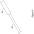
- FIGS 8 and 9 illustrate another example suture assembly 300 similar to suture assemblies 100 and 200.
- the suture assembly 300 includes a suture 380 fixed to a needle 310.
- the needle 310 is similar to needles 10 and 210, having a cylindrical body 320 and first and second end portions 340, 350, each having a sharp point 342, 352 and a depression 344, 354.
- the first and second sharp points 342, 352 are configured to pierce tissue such that the needle 310 may be used to suture tissue.
- Needle 310 may also include a lumen 322 extending through cylindrical body 320. Lumen 322 may extend through a central portion of cylindrical body 320 and may extend substantially perpendicular to the longitudinal axis X-X of cylindrical body 320.
- lumen 322 may extend through a non-central portion of cylindrical body 220 and/or be at an angle transverse to the longitudinal axis, but not perpendicular.
- Lumen 322 may include a first opening 324 on one side of cylindrical body 320 and a second opening (not shown) on the opposite side of cylindrical body 320 from the first opening 324.
- the first and second openings 324 may be identical.
- the lumen 322 is shown extending completely through the cylindrical body 320.
- the first, and/or second opening 324 may include a bevel or counter bore 327. In other examples, the first and/or second opening 324 may be flush with the exterior surface of the cylindrical body 320.
- the suture 380 may include a coupling member 390 fixed adjacent the terminal end 384 of the suture 380.
- the coupling member 390 may be inserted through the lumen 322 and fixed therein.
- the coupling member 390 may be a metal crimp tube.
- the crimp tube 390 may be placed over the suture 380 and then squeezed or crimped to fix it to the suture 380.
- the crimp tube 390 may then be inserted into the lumen 322 and fixed therein to secure the suture 380 to the needle 310, as shown in Figure 8 .
- the cylindrical body 320 and the crimp tube 390 may be metal and the crimp tube 390 may be welded or soldered within the lumen 322.
- the crimp tube 390 may be fixed within the lumen 322 with adhesive.
- FIG. 10 shows an alternative coupling member in the form of a wire 395 wrapped around the suture 380. As with the crimp tube 390, the wire 395 may be welded or soldered within the lumen 322 or fixed with adhesive.
- the needle 310 may include only the cylindrical body 320 and a single one of the first or second end portions 340, 350 with the sharp point 342, 352.
- the opposite end may be blunt.
- both the first and second end portions 340, 350 and their associated sharp points 342, 352 may be attached to the cylindrical body 320.
- the cylindrical body 320 may be made of the same or a different material from the first and/or second end portions 340, 350.
- the first and/or second end portions 340, 350 are made from a material that is more rigid than the material forming the cylindrical body 320.
- the entire needle 310 including the cylindrical body 320 and first and/or second end portion 340, 350 may be a single monolithic structure.
- the cylindrical body 320 and the first and/or second end portion 340, 350 may be solid.
- the suture 380 may include a knot or deformed (e.g., melted) region disposed within the coupling member 390 or above the coupling member 390, adjacent the outer surface of the cylindrical body 320.
- the suture 380 is fixedly coupled to needle 310 such that suture 380 remains within lumen 322 when a pulling force is applied to the suture 380, such as when using needle 310 to suture a patient.
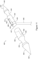
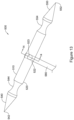
- FIGS 11 and 12 illustrate another example suture assembly 400 similar to suture assembly 100.
- the suture assembly 400 includes a suture 480 fixed to a needle 410.
- the needle 410 is similar to needle 10, having a cylindrical body 420 and first and second end portions 440, 450, each having a sharp point 442, 452 and a depression 444, 454.
- the first and second sharp points 442, 452 are configured to pierce tissue such that the needle 410 may be used to suture tissue.
- Needle 410 may also include a lumen 422 extending through cylindrical body 420. Lumen 422 may extend through a central portion of cylindrical body 420 and may extend substantially perpendicular to the longitudinal axis of cylindrical body 420.
- lumen 422 may extend through a non-central portion of cylindrical body 420 and/or be at an angle transverse to the longitudinal axis, but not perpendicular.
- Lumen 422 may include a first opening 424 on one side of cylindrical body 420 and a second opening (not shown) on the opposite side of cylindrical body 420 from the first opening 424.
- the lumen 422 may extend completely through the cylindrical body 420.
- the cylindrical body 420 may include a recess 428 in an outer surface configured to receive the first end region 482 of the suture 480.
- the suture 480 may be threaded through the lumen 422 and then the first end region 482 may be bent in an L shape and disposed within the recess 428.
- the second end portion 450 may include a sleeve portion 460 configured to slide over the cylindrical body 420 and compress the first end region 482 of the suture 480 within the recess 428.
- the recess 428 may be a channel that tapers as described for recess 28 in needle 10.
- First opening 424 of lumen 422 may be positioned within or otherwise in communication with recess 428.
- the sleeve portion 460 of the second end portion 450 may be a hollow cylinder or have a cavity configured to slide over the blunt end 427 of the cylindrical body 420, with a slot 462 extending through the wall in a longitudinal direction from one end towards the middle of the sleeve portion 460.
- the slot 462 may have a rounded end 464 configured to engage the suture 480 without damaging or cutting the suture 480.
- the recess 428 may have a depth measured transverse to the longitudinal axis that is less than the width of the suture 480.
- the sleeve portion 460 compresses the first end region 482 within the recess 428, thereby securing the suture 480 to the needle 410.
- the tapered shape of the recess 428 may provide for additional compression of the suture 80.
- the sleeve portion 460 may then be swaged onto the cylindrical body 420 to secure the second end portion 450 to the cylindrical body 420.
- the swaged region 466 of the sleeve portion 460 may include substantially the entire length of the sleeve portion 460. In other examples, only an end region of the sleeve portion 460 is swaged onto the cylindrical body 420. Swaging the sleeve portion 460 onto the cylindrical body 420 fixes the suture 480 to the needle 410 such that suture 480 remains within lumen 422 when a pulling force is applied to the suture 480, such as when using needle 410 to suture a patient.
- the sleeve portion 460 may be welded or soldered to the cylindrical body 420.
- adhesive or resin may be used in addition to the swaging, soldering, and/or welding to fix the sleeve portion 460 and/or suture 480 to the needle 410.
- the sleeve portion 460 may be an interference fit with the cylindrical body 420.
- the first end region 482 of the suture 480 may be deformed, e.g., melted, to conform to the shape of the recess 428 to aid in securing the suture to the needle 410.
- FIGS 13 and 14 illustrate another example suture assembly 500 similar to suture assemblies 100, 200, 300.
- the suture assembly 500 includes a suture 580 fixed to a needle 510.
- the needle 510 is similar to needles 10, 210, 310 having a cylindrical body 520 and first and second end portions 540, 550, each having a sharp point 542, 552 and a depression 544, 554.
- the first and second sharp points 542, 552 are configured to pierce tissue such that the needle 510 may be used to suture tissue.
- Needle 510 may also include a first lumen 522 extending through cylindrical body 520.
- First lumen 522 may extend through a central portion of cylindrical body 520 and may extend substantially perpendicular to the longitudinal axis of cylindrical body 520.
- first lumen 522 may extend through a non-central portion of cylindrical body 520.
- the first lumen 522 is shown extending completely through the cylindrical body 520. In some examples, the first lumen 522 may extend only part way through the cylindrical body 520.
- a second lumen 523 may extend through the cylindrical body 520 transverse to and intersecting the first lumen 522, as shown in Figure 14 .
- the suture 580 may be inserted through the first lumen 522.
- a first fixation member 592 may be inserted through the second lumen 523 from a first direction and a second fixation member 594 may be inserted through the second lumen 523 from a second direction.
- the first and second fixation members 592, 594 may be advanced until they engage and pinch the suture 580 between them.
- the first and second fixation members 592, 594 may be screws that threadingly engage an internally threaded second lumen 523.
- first and second fixation members 592, 594 may engage the second lumen 523 with a friction fit.
- the cylindrical body 520 and the first and second fixation members 592, 594 may be metal and the first and second fixation members 592, 594 may be welded or soldered within the second lumen 523.
- the first and second fixation members 592, 594 may be fixed within the second lumen 523 with adhesive.
- the needle 510 may include only the cylindrical body 520 and a single one of the first or second end portions 540, 550 with the sharp point 542, 552.
- the opposite end may be blunt.
- both the first and second end portions 540, 550 and their respective sharp point 542, 552 may be attached to the cylindrical body 520.
- the first and second sharp points 542, 552 are configured to pierce tissue such that the needle 510 may be used to suture tissue.
- the cylindrical body 520 may be attached to the first and/or second end portion 540, 550 via welding, soldering, swaging, or adhesive.
- the cylindrical body 520 may be made of the same or a different material from the first and/or second end portions 540, 550.
- first and/or second end portions 540, 550 are made from a material that is more rigid than the material forming the cylindrical body 520.
- the entire needle 510 including the cylindrical body 520 and first and/or second end portion 540, 550 may be a single monolithic structure.
- the cylindrical body 520 and the first and/or second end portion 540, 550 may be solid.
- the suture 580 may include a knot or deformed (e.g., melted) region disposed within the first lumen 522 or outside the first lumen 522, adjacent the outer surface of the cylindrical body 520.
- the suture 580 is fixedly coupled to needle 510 such that suture 580 remains within the first lumen 522 when a pulling force is applied to the suture 580, such as when using needle 510 to suture a patient.
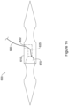
- FIGs 15 and 16 illustrate another example suture assembly 600 similar to suture assembly 100.
- the suture assembly 600 includes a suture 680 fixed to a needle 610.
- the needle 610 is similar to needle 10, having a cylindrical body 620 and first and second end portions 640, 650, each having a sharp point 642, 652 and a depression 644, 654.
- the first and second sharp points 642, 652 are configured to pierce tissue such that the needle 610 may be used to suture tissue.
- Needle 610 may also include a first lumen portion 622 extending part way into cylindrical body 620, as shown by the dashed lines in Figure 15 .
- First lumen portion 622 may extend into a central portion of cylindrical body 620 and may extend substantially perpendicular to the longitudinal axis of cylindrical body 620.
- first lumen portion 622 may extend through a non-central portion of cylindrical body 620 and/or be at an angle transverse to the longitudinal axis, but not perpendicular.
- the first lumen portion 622 may intersect a second lumen portion 625 extending longitudinally through the cylindrical body 620.
- the cylindrical body 620 may have a single lumen extending from the cavity 672 to an opening in the wall of the cylindrical body 620 (not shown). The single lumen may be curved or straight.
- the cylindrical body 620 may include a cavity 672 in an end face 674 opposite the sharp point 642.
- the cavity 672 is in communication with the second lumen portion 625 and may be configured to receive a protrusion 670 disposed on an end of the second end portion 650.
- the protrusion 670 may be received in the cavity 672 with a friction fit.
- the combination of first and second lumen portions 622, 625 and cavity 672 provide a pathway for the suture 680.
- the suture 680 may be threaded through the first lumen portion 622, second lumen portion 625, and into the cavity 672.
- the terminal end of the suture 680 may reside within the cavity 672.
- the protrusion 670 is then inserted into the cavity 672, thereby securing the suture 680 to the needle 610 such that suture 680 remains within the cavity 672 and the first and second lumen portions 622, 625 when a pulling force is applied to the suture 680, such as when using needle 610 to suture a patient.
- the protrusion 670 may be welded or soldered to the cavity 672 or the end face 674 of the cylindrical body 620.
- the protrusion 670 and/or the suture 680 may be fixed to the needle 610 with adhesive or resin.
- the end region of the suture 680 may be deformed, e.g., melted, to conform to the shape of one or more of the cavity 672, first lumen portion 622, or second lumen portion 625, to aid in securing the suture 680 to the needle 610.
- FIGs 17 and 18 illustrate additional example suture assemblies 700, 800 similar to suture assembly 300.
- the suture assembly 700 shown in Figure 17 includes a suture 780 fixed to a needle 710.
- the needle 710 is similar to needle 310, having a cylindrical body 720 and first and second end portions 740, 750, each having a sharp point 742, 752 and a depression 744, 754.
- the first and second sharp points 742, 752 are configured to pierce tissue such that the needle 710 may be used to suture tissue.
- Needle 710 may also include a lumen 722 extending through cylindrical body 720. Lumen 722 may extend through a central portion of cylindrical body 720 and may extend substantially perpendicular to the longitudinal axis of cylindrical body 720.
- lumen 722 may extend through a non-central portion of cylindrical body 720 and/or be at an angle transverse to the longitudinal axis, but not perpendicular.
- Lumen 722 may include a first opening 724 on one side of cylindrical body 720 and a second opening 726 on the opposite side of cylindrical body 720 from the first opening 724.
- the first and second openings 724, 726 may be identical.
- the lumen 722 is shown extending completely through the cylindrical body 720.
- the first, and/or second opening 724, 726 may include a bevel or counter bore as shown in Figure 8 .
- the first and/or second opening 724, 726 may be flush with the exterior surface of the cylindrical body 720 as shown in Figure 17 .
- the suture 780 may be inserted through the lumen 722 and a knot 785 tied in the end to prevent the suture 780 from being removed from the lumen 722 through the second opening 726, thereby securing the suture 780 to the needle 710, as shown in Figure 17 .
- the suture 780 may have a bulbous end, such that the end 785 is larger than the lumen 722.
- the bulbous end may be formed by deforming, or melting.
- the suture 780 may be fixed within the lumen 722 with adhesive or adhesive may be added to the knot 785 to secure the knot to the outer surface of the cylindrical body 720.
- Figure 18 shows a suture assembly 800 similar to suture assembly 700 but with a second lumen 821 spaced apart longitudinally from the first lumen 822.
- the suture assembly 800 shown in Figure 18 includes a suture 880 fixed to a needle 810.
- the needle 810 is similar to needle 710, having a cylindrical body 820 and first and second end portions 840, 850, each having a sharp point 842, 852 and a depression 844, 854.
- the first and second sharp points 842, 852 are configured to pierce tissue such that the needle 810 may be used to suture tissue.
- Needle 810 includes a first lumen 822 and a second lumen 821 extending through cylindrical body 820.
- Lumens 822, 821 may extend through a central portion of cylindrical body 820 and may extend substantially perpendicular to the longitudinal axis of cylindrical body 820. In other examples, lumens 822, 821 may extend through a non-central portion of cylindrical body 820 and/or be at an angle transverse to the longitudinal axis, but not perpendicular. Lumens 822, 821 may each include a first opening 824, 825 on one side of cylindrical body 820 and a second opening 826, 829 on the opposite side of cylindrical body 820 from the first opening 824, 825. The first openings 824, 825 and second openings 826, 829 may be identical. The first and second lumens 822, 821 are shown extending completely through the cylindrical body 820.
- first openings 824, 825, and/or second openings 826, 829 may include a bevel or counter bore as shown in Figure 8 .
- first and/or second openings may be flush with the exterior surface of the cylindrical body 820 as shown in Figure 18 .
- the suture 880 may be inserted through the second opening 826, into the first lumen 822, out the first opening 824 of the first lumen 822, across the outer surface of the cylindrical body 820, into the first opening 825 of the second lumen 821, through the second lumen 821 and out the second opening 829 of the second lumen 821.
- a knot 885 may be tied in the end to prevent the suture 880 from being removed from the lumens 822, 821 through the second opening 826, thereby securing the suture 880 to the needle 810 such that suture 880 remains within lumens 822, 821 when a pulling force is applied to the suture 880, such as when using needle 810 to suture a patient.
- the suture 880 may be fixed within the first and/or second lumen 822, 821 with adhesive or adhesive may be added to the knot 885 to secure the knot to the cylindrical body 820.
- the needles 710, 810 may include only the cylindrical body 720, 820 and a single one of the first end portion 740, 840 or second end portion 750, 850 with its associated sharp point 742, 842, 752, 852. The opposite end may be blunt.
- the needles 710, 810 may include both the first and second end portions 740, 840, 750, 850 and their associated sharp points, as illustrated.
- the cylindrical body 720, 820 may be made of the same or a different material from the first and/or second end portions 740, 840, 750, 850.
- first and/or second end portions 740, 840, 750, 850 are made from a material that is more rigid than the material forming the cylindrical body 720, 820.
- the entire needle 710, 810 including the cylindrical body 720, 820 and first and/or second end portion 740, 840, 750, 850 may be a single monolithic structure.
- the suture 80, 280, 380, 480, 580, 680, 780, 880 may be cylindrical and may be polyproplylene.
- the suture may be polyester, nylon, polyglycolic acid, polylactic acid, polymer materials, or any other absorbable or non-absorbable biocompatible material.
- variety of different metals may be used to make the needle 10, 210, 310, 410, 510, 610, 710, 810.
- suitable metals include titanium, stainless steel, magnesium, cobalt chromium and others.
- the devices described herein may include any suitable polymeric material, including biocompatible materials such as polyurethane or silicone.
- suitable polymers include but are not limited to polytetrafluoroethylene (PTFE), ethylene tetrafluoroethylene (ETFE), fluorinated ethylene propylene (FEP), polyoxymethylene (POM, for example, DELRIN ® available from DuPont), polyether block ester, polyurethane (for example, Polyurethane 85A), polypropylene (PP), polyvinylchloride (PVC), polyether-ester (for example, ARNITEL ® available from DSM Engineering Plastics), ether or ester based copolymers (for example, butylene/poly(alkylene ether) phthalate and/or other polyester elastomers such as HYTREL ® available from DuPont), polyamide (for example, DURETHAN ® available from Bayer or CRISTAMID ® available from Elf Atochem), e
- PTFE poly
Landscapes
- Health & Medical Sciences (AREA)
- Life Sciences & Earth Sciences (AREA)
- Surgery (AREA)
- Heart & Thoracic Surgery (AREA)
- Engineering & Computer Science (AREA)
- Biomedical Technology (AREA)
- Nuclear Medicine, Radiotherapy & Molecular Imaging (AREA)
- Medical Informatics (AREA)
- Molecular Biology (AREA)
- Animal Behavior & Ethology (AREA)
- General Health & Medical Sciences (AREA)
- Public Health (AREA)
- Veterinary Medicine (AREA)
- Surgical Instruments (AREA)
Claims (11)
- Dispositif médical (100) comprenant :
une aiguille (10) configurée pour être utilisée pour suturer le tissu, l'aiguille comprenant :un corps cylindrique (20) s'étendant le long d'un axe longitudinal (X-X) entre les première et deuxième extrémités du corps cylindrique ;une lumière (22) s'étendant à travers le corps cylindrique transversalement par rapport à l'axe longitudinal, la lumière ayant une première ouverture (24) et une deuxième ouverture (26) opposée à la première ouverture ; etune première partie d'extrémité (40) au niveau de la première extrémité du corps cylindrique, dans lequel la première partie d'extrémité comprend une première pointe pointue (42) configurée pour percer le tissu ;dans lequel une surface externe du corps cylindrique définit un premier enfoncement (28) en communication avec la première ouverture de la lumière et configuré pour recevoir une région d'extrémité (82) d'une suture (80) ; etun manchon (60) configuré pour coulisser sur le corps cylindrique et comprimer la région d'extrémité de la suture à l'intérieur du premier enfoncement,dans lequel le premier enfoncement est un premier canal s'étendant longitudinalement à partir de la première ouverture de la lumière vers la première pointe pointue,dans lequel la surface externe du corps cylindrique définit un deuxième enfoncement (29) en communication avec la première ouverture de la lumière, dans lequel le deuxième évidement est un deuxième canal s'étendant longitudinalement à partir de la première ouverture de la lumière dans une direction à l'opposé de la première pointe pointue. - Dispositif médical selon la revendication 1, dans lequel le manchon a une fente (62) dans sa paroi externe, la fente étant dimensionnée pour recevoir une partie de la suture s'étendant à partir de la deuxième ouverture de la lumière.
- Dispositif médical selon la revendication 1, dans lequel le premier canal se rétrécit progressivement de sorte qu'une première extrémité (31) du premier canal adjacent à la première ouverture de la lumière a une première profondeur qui est supérieure à une deuxième profondeur au niveau d'une deuxième extrémité (32) du premier canal opposée à la première extrémité du premier canal.
- Dispositif médical selon l'une quelconque des revendications 1 à 3, comprenant en outre une deuxième partie d'extrémité (50) au niveau de la deuxième extrémité du corps cylindrique, dans lequel la deuxième partie d'extrémité comprend une deuxième pointe pointue (52) configurée pour percer le tissu.
- Dispositif médical selon l'une quelconque des revendications 1 à 4, comprenant en outre une suture (80) ayant une première région d'extrémité (82) comprenant une première extrémité terminale (84), la première région d'extrémité s'étendant à travers la lumière et dans le premier enfoncement, dans lequel la première extrémité terminale est disposée à l'intérieur du premier enfoncement, dans lequel le manchon est disposé sur et comprime au moins une partie de la première région d'extrémité à l'intérieur du premier enfoncement, et la suture s'étend à partir de la deuxième ouverture de la lumière.
- Dispositif médical selon la revendication 5, dans lequel la première région d'extrémité de la suture à l'intérieur du premier enfoncement est déformée de sorte que la suture se conforme à une forme du premier enfoncement.
- Dispositif médical selon l'une quelconque des revendications 1 à 6, dans lequel le manchon est réalisé avec un matériau thermorétractable.
- Dispositif médical selon la revendication 1, dans lequel le manchon comprend une pointe pointue configurée pour percer le tissu.
- Dispositif médical selon la revendication 8, dans lequel le manchon comprend une cavité configurée pour recevoir la seconde extrémité du corps cylindrique.
- Dispositif médical selon la revendication 9, dans lequel le manchon a une fente dans sa paroi externe, la fente étant dimensionnée pour recevoir une partie de la suture s'étendant à partir de la seconde extrémité de la lumière.
- Dispositif médical selon la revendication 8, dans lequel le manchon est configuré pour être estampé sur le corps cylindrique.
Applications Claiming Priority (3)
| Application Number | Priority Date | Filing Date | Title |
|---|---|---|---|
| US201862727783P | 2018-09-06 | 2018-09-06 | |
| US201962848885P | 2019-05-16 | 2019-05-16 | |
| PCT/US2019/049774 WO2020051348A1 (fr) | 2018-09-06 | 2019-09-05 | Aiguille de suture endoscopique et procédés de fixation d'ensemble de suture |
Publications (2)
| Publication Number | Publication Date |
|---|---|
| EP3846699A1 EP3846699A1 (fr) | 2021-07-14 |
| EP3846699B1 true EP3846699B1 (fr) | 2024-11-27 |
Family
ID=67997709
Family Applications (2)
| Application Number | Title | Priority Date | Filing Date |
|---|---|---|---|
| EP19773238.1A Withdrawn EP3846700A1 (fr) | 2018-09-06 | 2019-09-05 | Dispositifs à aiguille de suture et méthodes d'attache de suture |
| EP19770244.2A Active EP3846699B1 (fr) | 2018-09-06 | 2019-09-05 | Aiguille de suture endoscopique |
Family Applications Before (1)
| Application Number | Title | Priority Date | Filing Date |
|---|---|---|---|
| EP19773238.1A Withdrawn EP3846700A1 (fr) | 2018-09-06 | 2019-09-05 | Dispositifs à aiguille de suture et méthodes d'attache de suture |
Country Status (7)
| Country | Link |
|---|---|
| US (3) | US20200078014A1 (fr) |
| EP (2) | EP3846700A1 (fr) |
| JP (2) | JP7374997B2 (fr) |
| KR (1) | KR102596714B1 (fr) |
| CN (4) | CN119606459A (fr) |
| CA (1) | CA3110413C (fr) |
| WO (2) | WO2020051348A1 (fr) |
Families Citing this family (4)
| Publication number | Priority date | Publication date | Assignee | Title |
|---|---|---|---|---|
| WO2020051348A1 (fr) | 2018-09-06 | 2020-03-12 | Boston Scientific Scimed, Inc. | Aiguille de suture endoscopique et procédés de fixation d'ensemble de suture |
| EP3922189B1 (fr) * | 2020-06-08 | 2025-04-23 | Suturion AB | Dispositif et procédé de sertissage |
| CN116509479B (zh) * | 2023-04-18 | 2023-11-07 | 南京思脉德医疗科技有限公司 | 一种血管缝合器的压线接头及固定缝合线的装置及工艺 |
| CN116421244B (zh) * | 2023-06-13 | 2023-09-05 | 二零二零(北京)医疗科技有限公司 | 一种医疗手术中的缝合线结构以及制作工艺 |
Family Cites Families (106)
| Publication number | Priority date | Publication date | Assignee | Title |
|---|---|---|---|---|
| US3880167A (en) * | 1974-01-28 | 1975-04-29 | Charles W Hardwick | Surgical needle apparatus |
| JPS5216294U (fr) * | 1975-07-23 | 1977-02-04 | ||
| US5358498A (en) * | 1990-02-01 | 1994-10-25 | Deknatel Technology Corporation, Inc. | Needled suture |
| GB9218754D0 (en) | 1992-09-04 | 1992-10-21 | Univ London | Device for use in securing a thread |
| CA2133377C (fr) * | 1993-10-08 | 2004-09-14 | H. Jonathan Tovey | Appareil de suture chirurgicale dote d'un mecanisme de chargement |
| US5478344A (en) | 1993-10-08 | 1995-12-26 | United States Surgical Corporation | Surgical suturing apparatus with loading mechanism |
| US6086608A (en) | 1996-02-22 | 2000-07-11 | Smith & Nephew, Inc. | Suture collet |
| US5693071A (en) | 1996-01-23 | 1997-12-02 | United States Surgical Corporation | Tapered surgical needles and surgical incision members |
| US5865836A (en) | 1996-09-20 | 1999-02-02 | United States Surgical Corporation | Needle-suture combination |
| CA2224366C (fr) * | 1996-12-11 | 2006-10-31 | Ethicon, Inc. | Dispositif de reparation meniscale |
| US6200329B1 (en) | 1998-08-31 | 2001-03-13 | Smith & Nephew, Inc. | Suture collet |
| US6663639B1 (en) | 1999-06-22 | 2003-12-16 | Ndo Surgical, Inc. | Methods and devices for tissue reconfiguration |
| US6835200B2 (en) | 1999-06-22 | 2004-12-28 | Ndo Surgical. Inc. | Method and devices for tissue reconfiguration |
| US6494888B1 (en) | 1999-06-22 | 2002-12-17 | Ndo Surgical, Inc. | Tissue reconfiguration |
| US6821285B2 (en) | 1999-06-22 | 2004-11-23 | Ndo Surgical, Inc. | Tissue reconfiguration |
| US7846180B2 (en) | 1999-06-22 | 2010-12-07 | Ethicon Endo-Surgery, Inc. | Tissue fixation devices and methods of fixing tissue |
| US6506196B1 (en) | 1999-06-22 | 2003-01-14 | Ndo Surgical, Inc. | Device and method for correction of a painful body defect |
| US8287554B2 (en) | 1999-06-22 | 2012-10-16 | Ethicon Endo-Surgery, Inc. | Method and devices for tissue reconfiguration |
| ATE329531T1 (de) | 1999-07-02 | 2006-07-15 | Quickpass Inc | Chirurgisches nähgerät |
| US6626917B1 (en) | 1999-10-26 | 2003-09-30 | H. Randall Craig | Helical suture instrument |
| US7993368B2 (en) | 2003-03-13 | 2011-08-09 | C.R. Bard, Inc. | Suture clips, delivery devices and methods |
| EP1284661B1 (fr) | 2000-05-19 | 2013-08-14 | C.R. Bard, Inc. | Dispositif de capture et de suture de tissus |
| US7220266B2 (en) | 2000-05-19 | 2007-05-22 | C. R. Bard, Inc. | Tissue capturing and suturing device and method |
| US6554845B1 (en) | 2000-09-15 | 2003-04-29 | PARÉ Surgical, Inc. | Suturing apparatus and method |
| US6755843B2 (en) | 2000-09-29 | 2004-06-29 | Olympus Optical Co., Ltd. | Endoscopic suturing device |
| US6719763B2 (en) | 2000-09-29 | 2004-04-13 | Olympus Optical Co., Ltd. | Endoscopic suturing device |
| US6569085B2 (en) | 2001-08-16 | 2003-05-27 | Syntheon, Llc | Methods and apparatus for delivering a medical instrument over an endoscope while the endoscope is in a body lumen |
| US7727246B2 (en) | 2000-12-06 | 2010-06-01 | Ethicon Endo-Surgery, Inc. | Methods for endoluminal treatment |
| US7232445B2 (en) | 2000-12-06 | 2007-06-19 | Id, Llc | Apparatus for the endoluminal treatment of gastroesophageal reflux disease (GERD) |
| US8062314B2 (en) | 2000-12-06 | 2011-11-22 | Ethicon Endo-Surgery, Inc. | Methods for the endoluminal treatment of gastroesophageal reflux disease (GERD) |
| US7235086B2 (en) | 2001-02-02 | 2007-06-26 | Lsi Solutions, Inc. | Crimping instrument with motion limiting feature |
| US8313496B2 (en) | 2001-02-02 | 2012-11-20 | Lsi Solutions, Inc. | System for endoscopic suturing |
| US6997931B2 (en) | 2001-02-02 | 2006-02-14 | Lsi Solutions, Inc. | System for endoscopic suturing |
| US6808491B2 (en) | 2001-05-21 | 2004-10-26 | Syntheon, Llc | Methods and apparatus for on-endoscope instruments having end effectors and combinations of on-endoscope and through-endoscope instruments |
| US7144401B2 (en) | 2001-06-07 | 2006-12-05 | Olympus Optical Co., Ltd. | Suturing device for endoscope |
| US8211123B2 (en) | 2001-12-21 | 2012-07-03 | Abbott Laboratories | Suture trimmer |
| US6746457B2 (en) | 2001-12-07 | 2004-06-08 | Abbott Laboratories | Snared suture trimmer |
| US7918867B2 (en) | 2001-12-07 | 2011-04-05 | Abbott Laboratories | Suture trimmer |
| US7094246B2 (en) | 2001-12-07 | 2006-08-22 | Abbott Laboratories | Suture trimmer |
| US6740030B2 (en) | 2002-01-04 | 2004-05-25 | Vision Sciences, Inc. | Endoscope assemblies having working channels with reduced bending and stretching resistance |
| US7530985B2 (en) | 2002-01-30 | 2009-05-12 | Olympus Corporation | Endoscopic suturing system |
| US7344545B2 (en) | 2002-01-30 | 2008-03-18 | Olympus Corporation | Endoscopic suturing system |
| US7618425B2 (en) | 2002-01-30 | 2009-11-17 | Olympus Corporation | Endoscopic suturing system |
| JP3890589B2 (ja) | 2002-04-15 | 2007-03-07 | ニプロ株式会社 | 心臓内縫合装置 |
| US6923807B2 (en) | 2002-06-27 | 2005-08-02 | Ethicon, Inc. | Helical device and method for aiding the ablation and assessment of tissue |
| JP4373146B2 (ja) | 2002-07-11 | 2009-11-25 | オリンパス株式会社 | 内視鏡用縫合装置 |
| US6936054B2 (en) | 2002-07-22 | 2005-08-30 | Boston Scientific Scimed, Inc. | Placing sutures |
| US6908427B2 (en) | 2002-12-30 | 2005-06-21 | PARÉ Surgical, Inc. | Flexible endoscope capsule |
| US7517357B2 (en) * | 2003-01-09 | 2009-04-14 | Linvatec Biomaterials | Knotless suture anchor |
| US8585714B2 (en) * | 2003-03-18 | 2013-11-19 | Depuy Mitek, Llc | Expandable needle suture apparatus and associated handle assembly with rotational suture manipulation system |
| US8066718B2 (en) * | 2003-03-18 | 2011-11-29 | Depuy Mitek, Inc. | Expandable needle suture apparatus and associated handle assembly |
| CA2525275C (fr) | 2003-05-16 | 2012-02-07 | C.R. Bard, Inc. | Systeme de suture endoscopique a plusieurs points et une seule intubation |
| ATE438335T1 (de) | 2003-09-15 | 2009-08-15 | Super Dimension Ltd | System aus zubehör zur verwendung mit bronchoskopen |
| JP4505244B2 (ja) | 2003-09-30 | 2010-07-21 | オリンパス株式会社 | 内視鏡鉗子口用アダプタ |
| US7347863B2 (en) | 2004-05-07 | 2008-03-25 | Usgi Medical, Inc. | Apparatus and methods for manipulating and securing tissue |
| US7361180B2 (en) | 2004-05-07 | 2008-04-22 | Usgi Medical, Inc. | Apparatus for manipulating and securing tissue |
| US20070219586A1 (en) * | 2004-01-23 | 2007-09-20 | Chalam Mahadevan | Suture Needle and Suture Assembly |
| JP4643328B2 (ja) | 2004-04-07 | 2011-03-02 | オリンパス株式会社 | 医療用結紮縫合装置 |
| US7736378B2 (en) | 2004-05-07 | 2010-06-15 | Usgi Medical, Inc. | Apparatus and methods for positioning and securing anchors |
| US20050250986A1 (en) | 2004-05-07 | 2005-11-10 | Usgi Medical Inc. | Removable apparatus and methods for manipulating and securing tissue |
| FR2880532B1 (fr) | 2005-01-07 | 2008-03-21 | Peter Cumbo | Aiguille chirurgicale et fil utilise avec cette aiguille |
| ITGE20050033A1 (it) * | 2005-05-18 | 2006-11-19 | Sergio Capurro | Ago a due punte atraumatico per sutura chirurgica costituito da due o piu' elementi componibili. |
| US7766925B2 (en) | 2005-06-13 | 2010-08-03 | Ethicon Endo-Surgery, Inc. | Surgical suturing apparatus |
| DE202005022017U1 (de) * | 2005-12-22 | 2012-05-10 | Hugh S., jun. West | Knochenanker mit zur Fixierung in kortikalem Knochengewebe und Spongiosa-Gewebe optimierter Gewindestruktur |
| US8105355B2 (en) | 2006-05-18 | 2012-01-31 | C.R. Bard, Inc. | Suture lock fastening device |
| US20070270908A1 (en) | 2006-05-19 | 2007-11-22 | Stokes Michael J | Suture locking method |
| EP2073725B1 (fr) | 2006-08-01 | 2015-05-06 | Cook Medical Technologies LLC | Système et procédé améliorés pour le traitement endoscopique de tissu |
| US20080086148A1 (en) | 2006-10-04 | 2008-04-10 | Endogastric Solutions, Inc. | Assemblies for deploying fasteners in tissue and snares for use in such assemblies |
| WO2008045376A2 (fr) | 2006-10-05 | 2008-04-17 | Tyco Healthcare Group Lp | Dispositif de suture axiale |
| US8702729B2 (en) | 2006-10-13 | 2014-04-22 | Boston Scientific Scimed, Inc. | Placing multiple sutures |
| US9033999B2 (en) * | 2006-12-04 | 2015-05-19 | Implicitcare, Llc | Surgical threading device with removable suture |
| WO2008098124A1 (fr) | 2007-02-07 | 2008-08-14 | Boston Scientific Scimed, Inc. | Bride de fixation |
| AU2008232742A1 (en) | 2007-03-30 | 2008-10-09 | Wilson-Cook Medical Inc. | Endoscopic securing system |
| WO2009052438A2 (fr) | 2007-10-19 | 2009-04-23 | Guided Delivery Systems Inc. | Dispositifs et procédés d'achèvement d'une intervention |
| JP5421927B2 (ja) | 2008-01-03 | 2014-02-19 | クック メディカル テクノロジーズ エルエルシー | 内視鏡を使用して穴を縫合するための医療装置、器具及び方法 |
| US20090259105A1 (en) | 2008-04-10 | 2009-10-15 | Miyano Hiromichi | Medical treatment system and suturing method |
| US8679136B2 (en) | 2008-06-17 | 2014-03-25 | Apollo Endosurgery, Inc. | Needle capture device |
| ES2734905T3 (es) | 2008-06-17 | 2019-12-12 | Apollo Endosurgery Inc | Sistema de sutura endoscópica |
| US9486126B2 (en) | 2008-06-17 | 2016-11-08 | Apollo Endosurgery, Inc. | Endoscopic helix tissue grasping device |
| WO2010036227A1 (fr) | 2008-09-29 | 2010-04-01 | C R . Bard, Inc . | Dispositif de suture endoscopique |
| US20100137681A1 (en) | 2008-11-21 | 2010-06-03 | Usgi Medical, Inc. | Endoscopic instrument management system |
| US20100174299A1 (en) * | 2009-01-05 | 2010-07-08 | Tyco Healthcare Group Lp | Method Of Using Barbed Sutures For Gastric Volume Reduction |
| KR20110113176A (ko) | 2009-01-26 | 2011-10-14 | 신세스 게엠바하 | 양방향 봉합사 통과기 |
| US20110098725A1 (en) | 2009-09-03 | 2011-04-28 | Usgi Medical, Inc. | Devices and methods for endolumenal weight loss treatments |
| US8709022B2 (en) * | 2011-05-24 | 2014-04-29 | Biomet Sports Medicine, Llc | Method and apparatus for passing a suture |
| US20120083838A1 (en) * | 2010-10-01 | 2012-04-05 | Tyco Healthcare Group Lp | Connectable End Effector |
| US9125646B2 (en) | 2010-11-15 | 2015-09-08 | Ethicon Endo-Surgery, Inc. | Needle for laparoscopic suturing instrument |
| US8540735B2 (en) | 2010-12-16 | 2013-09-24 | Apollo Endosurgery, Inc. | Endoscopic suture cinch system |
| SG192154A1 (en) | 2011-01-25 | 2013-08-30 | Univ Kagawa Nat Univ Corp | Suture device |
| KR101132841B1 (ko) * | 2011-03-07 | 2012-04-02 | 김영재 | 봉합사 |
| US10448946B2 (en) | 2013-03-12 | 2019-10-22 | Apollo Endosurgery Us, Inc. | Endoscopic suture cinch |
| ES2741201T3 (es) * | 2013-03-12 | 2020-02-10 | Allergan Holdings France S A S | Aguja roma para el suministro de hilos de relleno dérmico |
| WO2014164955A2 (fr) | 2013-03-12 | 2014-10-09 | Apollo Endosurgery, Inc. | Système d'ancres à suture endoscopique à ancres rechargeables |
| US20150126983A1 (en) | 2013-11-05 | 2015-05-07 | Apollo Endosurgery, Inc. | Incisionless Endoluminal Gastric Tissue Approximation for the Treatment Of Obesity |
| NL2012735B9 (en) * | 2014-05-01 | 2017-03-28 | Mellon Medical B V | Needle-suture combination. |
| CN107847227A (zh) * | 2015-06-11 | 2018-03-27 | 波士顿科学国际有限公司 | 柔性活检针 |
| WO2017058729A1 (fr) | 2015-09-29 | 2017-04-06 | Boston Scientific Scimed, Inc. | Dispositif de fermeture à passeur d'aiguille de torsion |
| US10639028B2 (en) | 2015-10-29 | 2020-05-05 | Apollo Endosurgery Us, Inc. | Endoscopic suture loop anchors and methods |
| CN108135448B (zh) | 2015-11-20 | 2022-05-31 | 波士顿科学医学有限公司 | 用于将辅助工具固定到微创介入工具的装置和方法 |
| US11141147B2 (en) | 2016-08-10 | 2021-10-12 | Apollo Endosurgery Us, Inc. | Endoscopic suturing system having external instrument channel |
| US11051800B2 (en) | 2016-08-10 | 2021-07-06 | Apollo Endosurgery Us, Inc. | Endoscopic suturing system having external instrument channel |
| US11129519B2 (en) | 2016-08-25 | 2021-09-28 | OTU Medical Inc. | Single-use endoscope with built-in optical fibers and fixtures |
| US10426457B2 (en) | 2017-02-07 | 2019-10-01 | Apollo Endosurgery Us, Inc. | Surgical fastener deployment system |
| US10932771B2 (en) | 2017-02-22 | 2021-03-02 | Boston Scientific Scimed, Inc. | Suture based closure device |
| US10973510B2 (en) * | 2017-05-02 | 2021-04-13 | Covidien Lp | Needle loading unit for surgical suturing apparatus |
| WO2020051348A1 (fr) | 2018-09-06 | 2020-03-12 | Boston Scientific Scimed, Inc. | Aiguille de suture endoscopique et procédés de fixation d'ensemble de suture |
-
2019
- 2019-09-05 WO PCT/US2019/049774 patent/WO2020051348A1/fr not_active Ceased
- 2019-09-05 EP EP19773238.1A patent/EP3846700A1/fr not_active Withdrawn
- 2019-09-05 EP EP19770244.2A patent/EP3846699B1/fr active Active
- 2019-09-05 US US16/561,232 patent/US20200078014A1/en not_active Abandoned
- 2019-09-05 US US16/561,933 patent/US11278272B2/en active Active
- 2019-09-05 CN CN202510009306.1A patent/CN119606459A/zh active Pending
- 2019-09-05 CN CN201980070820.9A patent/CN112912017B/zh active Active
- 2019-09-05 WO PCT/US2019/049683 patent/WO2020051291A1/fr not_active Ceased
- 2019-09-05 KR KR1020217009961A patent/KR102596714B1/ko active Active
- 2019-09-05 JP JP2021510964A patent/JP7374997B2/ja active Active
- 2019-09-05 CA CA3110413A patent/CA3110413C/fr active Active
- 2019-09-05 CN CN202510522457.7A patent/CN120324048A/zh active Pending
- 2019-09-05 CN CN201980057866.7A patent/CN112654309B/zh active Active
- 2019-09-05 JP JP2021512643A patent/JP7130852B2/ja active Active
-
2023
- 2023-01-19 US US18/156,650 patent/US12213663B2/en active Active
Also Published As
| Publication number | Publication date |
|---|---|
| US20230149013A1 (en) | 2023-05-18 |
| EP3846699A1 (fr) | 2021-07-14 |
| CN112654309B (zh) | 2025-01-21 |
| KR102596714B1 (ko) | 2023-11-02 |
| JP7374997B2 (ja) | 2023-11-07 |
| KR20210055737A (ko) | 2021-05-17 |
| US11278272B2 (en) | 2022-03-22 |
| CN120324048A (zh) | 2025-07-18 |
| CN112912017B (zh) | 2025-05-09 |
| CN112912017A (zh) | 2021-06-04 |
| US12213663B2 (en) | 2025-02-04 |
| JP2021534922A (ja) | 2021-12-16 |
| WO2020051291A1 (fr) | 2020-03-12 |
| CA3110413A1 (fr) | 2020-03-12 |
| CN119606459A (zh) | 2025-03-14 |
| EP3846700A1 (fr) | 2021-07-14 |
| US20200078014A1 (en) | 2020-03-12 |
| JP7130852B2 (ja) | 2022-09-05 |
| CN112654309A (zh) | 2021-04-13 |
| WO2020051348A1 (fr) | 2020-03-12 |
| CA3110413C (fr) | 2024-10-08 |
| JP2021536293A (ja) | 2021-12-27 |
| US20200078006A1 (en) | 2020-03-12 |
Similar Documents
| Publication | Publication Date | Title |
|---|---|---|
| EP3846699B1 (fr) | Aiguille de suture endoscopique | |
| US11957330B2 (en) | Endoscopic suture cinching and cutting device | |
| US10383719B2 (en) | Stent for medical use | |
| JP7853340B2 (ja) | 組織捕捉らせん装置 | |
| JP6959357B2 (ja) | カテーテル | |
| KR102052356B1 (ko) | 피부 리프팅 봉합사 삽입 캐뉼라 및 그 제조방법 | |
| US20260007400A1 (en) | Suture cinching and cutting device | |
| US20260000445A1 (en) | Medical device, medical device package, method for using medical device, and method for manufacturing medical device | |
| US20210338300A1 (en) | Cable crimp cap apparatus and method | |
| EP4673207A1 (fr) | Manchon de fixation et ensemble comprenant un tel manchon |
Legal Events
| Date | Code | Title | Description |
|---|---|---|---|
| STAA | Information on the status of an ep patent application or granted ep patent |
Free format text: STATUS: UNKNOWN |
|
| STAA | Information on the status of an ep patent application or granted ep patent |
Free format text: STATUS: THE INTERNATIONAL PUBLICATION HAS BEEN MADE |
|
| PUAI | Public reference made under article 153(3) epc to a published international application that has entered the european phase |
Free format text: ORIGINAL CODE: 0009012 |
|
| STAA | Information on the status of an ep patent application or granted ep patent |
Free format text: STATUS: REQUEST FOR EXAMINATION WAS MADE |
|
| 17P | Request for examination filed |
Effective date: 20210323 |
|
| AK | Designated contracting states |
Kind code of ref document: A1 Designated state(s): AL AT BE BG CH CY CZ DE DK EE ES FI FR GB GR HR HU IE IS IT LI LT LU LV MC MK MT NL NO PL PT RO RS SE SI SK SM TR |
|
| DAV | Request for validation of the european patent (deleted) | ||
| DAX | Request for extension of the european patent (deleted) | ||
| GRAP | Despatch of communication of intention to grant a patent |
Free format text: ORIGINAL CODE: EPIDOSNIGR1 |
|
| STAA | Information on the status of an ep patent application or granted ep patent |
Free format text: STATUS: GRANT OF PATENT IS INTENDED |
|
| INTG | Intention to grant announced |
Effective date: 20240624 |
|
| GRAS | Grant fee paid |
Free format text: ORIGINAL CODE: EPIDOSNIGR3 |
|
| GRAA | (expected) grant |
Free format text: ORIGINAL CODE: 0009210 |
|
| STAA | Information on the status of an ep patent application or granted ep patent |
Free format text: STATUS: THE PATENT HAS BEEN GRANTED |
|
| AK | Designated contracting states |
Kind code of ref document: B1 Designated state(s): AL AT BE BG CH CY CZ DE DK EE ES FI FR GB GR HR HU IE IS IT LI LT LU LV MC MK MT NL NO PL PT RO RS SE SI SK SM TR |
|
| REG | Reference to a national code |
Ref country code: GB Ref legal event code: FG4D |
|
| REG | Reference to a national code |
Ref country code: CH Ref legal event code: EP |
|
| REG | Reference to a national code |
Ref country code: DE Ref legal event code: R096 Ref document number: 602019062606 Country of ref document: DE |
|
| REG | Reference to a national code |
Ref country code: IE Ref legal event code: FG4D |
|
| REG | Reference to a national code |
Ref country code: NL Ref legal event code: FP |
|
| REG | Reference to a national code |
Ref country code: LT Ref legal event code: MG9D |
|
| PG25 | Lapsed in a contracting state [announced via postgrant information from national office to epo] |
Ref country code: HR Free format text: LAPSE BECAUSE OF FAILURE TO SUBMIT A TRANSLATION OF THE DESCRIPTION OR TO PAY THE FEE WITHIN THE PRESCRIBED TIME-LIMIT Effective date: 20241127 Ref country code: IS Free format text: LAPSE BECAUSE OF FAILURE TO SUBMIT A TRANSLATION OF THE DESCRIPTION OR TO PAY THE FEE WITHIN THE PRESCRIBED TIME-LIMIT Effective date: 20250327 Ref country code: PT Free format text: LAPSE BECAUSE OF FAILURE TO SUBMIT A TRANSLATION OF THE DESCRIPTION OR TO PAY THE FEE WITHIN THE PRESCRIBED TIME-LIMIT Effective date: 20250327 |
|
| PG25 | Lapsed in a contracting state [announced via postgrant information from national office to epo] |
Ref country code: FI Free format text: LAPSE BECAUSE OF FAILURE TO SUBMIT A TRANSLATION OF THE DESCRIPTION OR TO PAY THE FEE WITHIN THE PRESCRIBED TIME-LIMIT Effective date: 20241127 |
|
| REG | Reference to a national code |
Ref country code: AT Ref legal event code: MK05 Ref document number: 1744926 Country of ref document: AT Kind code of ref document: T Effective date: 20241127 |
|
| PG25 | Lapsed in a contracting state [announced via postgrant information from national office to epo] |
Ref country code: BG Free format text: LAPSE BECAUSE OF FAILURE TO SUBMIT A TRANSLATION OF THE DESCRIPTION OR TO PAY THE FEE WITHIN THE PRESCRIBED TIME-LIMIT Effective date: 20241127 |
|
| PG25 | Lapsed in a contracting state [announced via postgrant information from national office to epo] |
Ref country code: ES Free format text: LAPSE BECAUSE OF FAILURE TO SUBMIT A TRANSLATION OF THE DESCRIPTION OR TO PAY THE FEE WITHIN THE PRESCRIBED TIME-LIMIT Effective date: 20241127 |
|
| PG25 | Lapsed in a contracting state [announced via postgrant information from national office to epo] |
Ref country code: NO Free format text: LAPSE BECAUSE OF FAILURE TO SUBMIT A TRANSLATION OF THE DESCRIPTION OR TO PAY THE FEE WITHIN THE PRESCRIBED TIME-LIMIT Effective date: 20250227 |
|
| PG25 | Lapsed in a contracting state [announced via postgrant information from national office to epo] |
Ref country code: LV Free format text: LAPSE BECAUSE OF FAILURE TO SUBMIT A TRANSLATION OF THE DESCRIPTION OR TO PAY THE FEE WITHIN THE PRESCRIBED TIME-LIMIT Effective date: 20241127 Ref country code: GR Free format text: LAPSE BECAUSE OF FAILURE TO SUBMIT A TRANSLATION OF THE DESCRIPTION OR TO PAY THE FEE WITHIN THE PRESCRIBED TIME-LIMIT Effective date: 20250228 Ref country code: AT Free format text: LAPSE BECAUSE OF FAILURE TO SUBMIT A TRANSLATION OF THE DESCRIPTION OR TO PAY THE FEE WITHIN THE PRESCRIBED TIME-LIMIT Effective date: 20241127 |
|
| PG25 | Lapsed in a contracting state [announced via postgrant information from national office to epo] |
Ref country code: PL Free format text: LAPSE BECAUSE OF FAILURE TO SUBMIT A TRANSLATION OF THE DESCRIPTION OR TO PAY THE FEE WITHIN THE PRESCRIBED TIME-LIMIT Effective date: 20241127 |
|
| PG25 | Lapsed in a contracting state [announced via postgrant information from national office to epo] |
Ref country code: RS Free format text: LAPSE BECAUSE OF FAILURE TO SUBMIT A TRANSLATION OF THE DESCRIPTION OR TO PAY THE FEE WITHIN THE PRESCRIBED TIME-LIMIT Effective date: 20250227 |
|
| PG25 | Lapsed in a contracting state [announced via postgrant information from national office to epo] |
Ref country code: SM Free format text: LAPSE BECAUSE OF FAILURE TO SUBMIT A TRANSLATION OF THE DESCRIPTION OR TO PAY THE FEE WITHIN THE PRESCRIBED TIME-LIMIT Effective date: 20241127 |
|
| PG25 | Lapsed in a contracting state [announced via postgrant information from national office to epo] |
Ref country code: DK Free format text: LAPSE BECAUSE OF FAILURE TO SUBMIT A TRANSLATION OF THE DESCRIPTION OR TO PAY THE FEE WITHIN THE PRESCRIBED TIME-LIMIT Effective date: 20241127 |
|
| PG25 | Lapsed in a contracting state [announced via postgrant information from national office to epo] |
Ref country code: EE Free format text: LAPSE BECAUSE OF FAILURE TO SUBMIT A TRANSLATION OF THE DESCRIPTION OR TO PAY THE FEE WITHIN THE PRESCRIBED TIME-LIMIT Effective date: 20241127 |
|
| PG25 | Lapsed in a contracting state [announced via postgrant information from national office to epo] |
Ref country code: RO Free format text: LAPSE BECAUSE OF FAILURE TO SUBMIT A TRANSLATION OF THE DESCRIPTION OR TO PAY THE FEE WITHIN THE PRESCRIBED TIME-LIMIT Effective date: 20241127 |
|
| PG25 | Lapsed in a contracting state [announced via postgrant information from national office to epo] |
Ref country code: SK Free format text: LAPSE BECAUSE OF FAILURE TO SUBMIT A TRANSLATION OF THE DESCRIPTION OR TO PAY THE FEE WITHIN THE PRESCRIBED TIME-LIMIT Effective date: 20241127 |
|
| PG25 | Lapsed in a contracting state [announced via postgrant information from national office to epo] |
Ref country code: CZ Free format text: LAPSE BECAUSE OF FAILURE TO SUBMIT A TRANSLATION OF THE DESCRIPTION OR TO PAY THE FEE WITHIN THE PRESCRIBED TIME-LIMIT Effective date: 20241127 |
|
| PG25 | Lapsed in a contracting state [announced via postgrant information from national office to epo] |
Ref country code: IT Free format text: LAPSE BECAUSE OF FAILURE TO SUBMIT A TRANSLATION OF THE DESCRIPTION OR TO PAY THE FEE WITHIN THE PRESCRIBED TIME-LIMIT Effective date: 20241127 |
|
| REG | Reference to a national code |
Ref country code: DE Ref legal event code: R097 Ref document number: 602019062606 Country of ref document: DE |
|
| PG25 | Lapsed in a contracting state [announced via postgrant information from national office to epo] |
Ref country code: SE Free format text: LAPSE BECAUSE OF FAILURE TO SUBMIT A TRANSLATION OF THE DESCRIPTION OR TO PAY THE FEE WITHIN THE PRESCRIBED TIME-LIMIT Effective date: 20241127 |
|
| PGFP | Annual fee paid to national office [announced via postgrant information from national office to epo] |
Ref country code: NL Payment date: 20250820 Year of fee payment: 7 |
|
| PLBE | No opposition filed within time limit |
Free format text: ORIGINAL CODE: 0009261 |
|
| STAA | Information on the status of an ep patent application or granted ep patent |
Free format text: STATUS: NO OPPOSITION FILED WITHIN TIME LIMIT |
|
| PGFP | Annual fee paid to national office [announced via postgrant information from national office to epo] |
Ref country code: DE Payment date: 20250820 Year of fee payment: 7 |
|
| PGFP | Annual fee paid to national office [announced via postgrant information from national office to epo] |
Ref country code: GB Payment date: 20250827 Year of fee payment: 7 |
|
| PGFP | Annual fee paid to national office [announced via postgrant information from national office to epo] |
Ref country code: IE Payment date: 20250822 Year of fee payment: 7 |
|
| 26N | No opposition filed |
Effective date: 20250828 |