EP3846927B1 - Reaktor zur durchführung einer reaktion zwischen zwei nicht mischbaren fluiden unterschiedlicher dichte - Google Patents
Reaktor zur durchführung einer reaktion zwischen zwei nicht mischbaren fluiden unterschiedlicher dichte Download PDFInfo
- Publication number
- EP3846927B1 EP3846927B1 EP19762155.0A EP19762155A EP3846927B1 EP 3846927 B1 EP3846927 B1 EP 3846927B1 EP 19762155 A EP19762155 A EP 19762155A EP 3846927 B1 EP3846927 B1 EP 3846927B1
- Authority
- EP
- European Patent Office
- Prior art keywords
- zone
- fluid
- plug
- backmixed
- reactor
- Prior art date
- Legal status (The legal status is an assumption and is not a legal conclusion. Google has not performed a legal analysis and makes no representation as to the accuracy of the status listed.)
- Active
Links
Images

Classifications
-
- B—PERFORMING OPERATIONS; TRANSPORTING
- B01—PHYSICAL OR CHEMICAL PROCESSES OR APPARATUS IN GENERAL
- B01J—CHEMICAL OR PHYSICAL PROCESSES, e.g. CATALYSIS OR COLLOID CHEMISTRY; THEIR RELEVANT APPARATUS
- B01J3/00—Processes of utilising sub-atmospheric or super-atmospheric pressure to effect chemical or physical change of matter; Apparatus therefor
- B01J3/04—Pressure vessels, e.g. autoclaves
- B01J3/042—Pressure vessels, e.g. autoclaves in the form of a tube
-
- B—PERFORMING OPERATIONS; TRANSPORTING
- B01—PHYSICAL OR CHEMICAL PROCESSES OR APPARATUS IN GENERAL
- B01J—CHEMICAL OR PHYSICAL PROCESSES, e.g. CATALYSIS OR COLLOID CHEMISTRY; THEIR RELEVANT APPARATUS
- B01J10/00—Chemical processes in general for reacting liquid with gaseous media other than in the presence of solid particles, or apparatus specially adapted therefor
-
- B—PERFORMING OPERATIONS; TRANSPORTING
- B01—PHYSICAL OR CHEMICAL PROCESSES OR APPARATUS IN GENERAL
- B01J—CHEMICAL OR PHYSICAL PROCESSES, e.g. CATALYSIS OR COLLOID CHEMISTRY; THEIR RELEVANT APPARATUS
- B01J19/00—Chemical, physical or physico-chemical processes in general; Their relevant apparatus
- B01J19/0053—Details of the reactor
- B01J19/006—Baffles
-
- B—PERFORMING OPERATIONS; TRANSPORTING
- B01—PHYSICAL OR CHEMICAL PROCESSES OR APPARATUS IN GENERAL
- B01J—CHEMICAL OR PHYSICAL PROCESSES, e.g. CATALYSIS OR COLLOID CHEMISTRY; THEIR RELEVANT APPARATUS
- B01J19/00—Chemical, physical or physico-chemical processes in general; Their relevant apparatus
- B01J19/24—Stationary reactors without moving elements inside
- B01J19/2415—Tubular reactors
- B01J19/2435—Loop-type reactors
-
- B—PERFORMING OPERATIONS; TRANSPORTING
- B01—PHYSICAL OR CHEMICAL PROCESSES OR APPARATUS IN GENERAL
- B01J—CHEMICAL OR PHYSICAL PROCESSES, e.g. CATALYSIS OR COLLOID CHEMISTRY; THEIR RELEVANT APPARATUS
- B01J19/00—Chemical, physical or physico-chemical processes in general; Their relevant apparatus
- B01J19/24—Stationary reactors without moving elements inside
- B01J19/2415—Tubular reactors
- B01J19/244—Concentric tubes
-
- B—PERFORMING OPERATIONS; TRANSPORTING
- B01—PHYSICAL OR CHEMICAL PROCESSES OR APPARATUS IN GENERAL
- B01J—CHEMICAL OR PHYSICAL PROCESSES, e.g. CATALYSIS OR COLLOID CHEMISTRY; THEIR RELEVANT APPARATUS
- B01J19/00—Chemical, physical or physico-chemical processes in general; Their relevant apparatus
- B01J19/26—Nozzle-type reactors, i.e. the distribution of the initial reactants within the reactor is effected by their introduction or injection through nozzles
-
- C—CHEMISTRY; METALLURGY
- C07—ORGANIC CHEMISTRY
- C07B—GENERAL METHODS OF ORGANIC CHEMISTRY; APPARATUS THEREFOR
- C07B53/00—Asymmetric syntheses
-
- C—CHEMISTRY; METALLURGY
- C07—ORGANIC CHEMISTRY
- C07C—ACYCLIC OR CARBOCYCLIC COMPOUNDS
- C07C29/00—Preparation of compounds having hydroxy or O-metal groups bound to a carbon atom not belonging to a six-membered aromatic ring
- C07C29/17—Preparation of compounds having hydroxy or O-metal groups bound to a carbon atom not belonging to a six-membered aromatic ring by hydrogenation of carbon-to-carbon double or triple bonds
- C07C29/172—Preparation of compounds having hydroxy or O-metal groups bound to a carbon atom not belonging to a six-membered aromatic ring by hydrogenation of carbon-to-carbon double or triple bonds with the obtention of a fully saturated alcohol
-
- C—CHEMISTRY; METALLURGY
- C07—ORGANIC CHEMISTRY
- C07C—ACYCLIC OR CARBOCYCLIC COMPOUNDS
- C07C29/00—Preparation of compounds having hydroxy or O-metal groups bound to a carbon atom not belonging to a six-membered aromatic ring
- C07C29/56—Preparation of compounds having hydroxy or O-metal groups bound to a carbon atom not belonging to a six-membered aromatic ring by isomerisation
-
- C—CHEMISTRY; METALLURGY
- C07—ORGANIC CHEMISTRY
- C07C—ACYCLIC OR CARBOCYCLIC COMPOUNDS
- C07C45/00—Preparation of compounds having >C = O groups bound only to carbon or hydrogen atoms; Preparation of chelates of such compounds
- C07C45/61—Preparation of compounds having >C = O groups bound only to carbon or hydrogen atoms; Preparation of chelates of such compounds by reactions not involving the formation of >C = O groups
- C07C45/62—Preparation of compounds having >C = O groups bound only to carbon or hydrogen atoms; Preparation of chelates of such compounds by reactions not involving the formation of >C = O groups by hydrogenation of carbon-to-carbon double or triple bonds
-
- B—PERFORMING OPERATIONS; TRANSPORTING
- B01—PHYSICAL OR CHEMICAL PROCESSES OR APPARATUS IN GENERAL
- B01J—CHEMICAL OR PHYSICAL PROCESSES, e.g. CATALYSIS OR COLLOID CHEMISTRY; THEIR RELEVANT APPARATUS
- B01J2219/00—Chemical, physical or physico-chemical processes in general; Their relevant apparatus
- B01J2219/00761—Details of the reactor
- B01J2219/00763—Baffles
- B01J2219/00765—Baffles attached to the reactor wall
- B01J2219/00768—Baffles attached to the reactor wall vertical
-
- B—PERFORMING OPERATIONS; TRANSPORTING
- B01—PHYSICAL OR CHEMICAL PROCESSES OR APPARATUS IN GENERAL
- B01J—CHEMICAL OR PHYSICAL PROCESSES, e.g. CATALYSIS OR COLLOID CHEMISTRY; THEIR RELEVANT APPARATUS
- B01J2219/00—Chemical, physical or physico-chemical processes in general; Their relevant apparatus
- B01J2219/00761—Details of the reactor
- B01J2219/00763—Baffles
- B01J2219/00765—Baffles attached to the reactor wall
- B01J2219/00777—Baffles attached to the reactor wall horizontal
-
- B—PERFORMING OPERATIONS; TRANSPORTING
- B01—PHYSICAL OR CHEMICAL PROCESSES OR APPARATUS IN GENERAL
- B01J—CHEMICAL OR PHYSICAL PROCESSES, e.g. CATALYSIS OR COLLOID CHEMISTRY; THEIR RELEVANT APPARATUS
- B01J2219/00—Chemical, physical or physico-chemical processes in general; Their relevant apparatus
- B01J2219/08—Processes employing the direct application of electric or wave energy, or particle radiation; Apparatus therefor
- B01J2219/0871—Heating or cooling of the reactor
-
- B—PERFORMING OPERATIONS; TRANSPORTING
- B01—PHYSICAL OR CHEMICAL PROCESSES OR APPARATUS IN GENERAL
- B01J—CHEMICAL OR PHYSICAL PROCESSES, e.g. CATALYSIS OR COLLOID CHEMISTRY; THEIR RELEVANT APPARATUS
- B01J2219/00—Chemical, physical or physico-chemical processes in general; Their relevant apparatus
- B01J2219/08—Processes employing the direct application of electric or wave energy, or particle radiation; Apparatus therefor
- B01J2219/0873—Materials to be treated
- B01J2219/0881—Two or more materials
- B01J2219/0884—Gas-liquid
-
- B—PERFORMING OPERATIONS; TRANSPORTING
- B01—PHYSICAL OR CHEMICAL PROCESSES OR APPARATUS IN GENERAL
- B01J—CHEMICAL OR PHYSICAL PROCESSES, e.g. CATALYSIS OR COLLOID CHEMISTRY; THEIR RELEVANT APPARATUS
- B01J2219/00—Chemical, physical or physico-chemical processes in general; Their relevant apparatus
- B01J2219/18—Details relating to the spatial orientation of the reactor
- B01J2219/185—Details relating to the spatial orientation of the reactor vertical
-
- B—PERFORMING OPERATIONS; TRANSPORTING
- B01—PHYSICAL OR CHEMICAL PROCESSES OR APPARATUS IN GENERAL
- B01J—CHEMICAL OR PHYSICAL PROCESSES, e.g. CATALYSIS OR COLLOID CHEMISTRY; THEIR RELEVANT APPARATUS
- B01J2219/00—Chemical, physical or physico-chemical processes in general; Their relevant apparatus
- B01J2219/19—Details relating to the geometry of the reactor
- B01J2219/194—Details relating to the geometry of the reactor round
- B01J2219/1941—Details relating to the geometry of the reactor round circular or disk-shaped
- B01J2219/1943—Details relating to the geometry of the reactor round circular or disk-shaped cylindrical
-
- B—PERFORMING OPERATIONS; TRANSPORTING
- B01—PHYSICAL OR CHEMICAL PROCESSES OR APPARATUS IN GENERAL
- B01J—CHEMICAL OR PHYSICAL PROCESSES, e.g. CATALYSIS OR COLLOID CHEMISTRY; THEIR RELEVANT APPARATUS
- B01J2219/00—Chemical, physical or physico-chemical processes in general; Their relevant apparatus
- B01J2219/24—Stationary reactors without moving elements inside
- B01J2219/2401—Reactors comprising multiple separate flow channels
- B01J2219/245—Plate-type reactors
- B01J2219/2474—Mixing means, e.g. fins or baffles attached to the plates
-
- B—PERFORMING OPERATIONS; TRANSPORTING
- B01—PHYSICAL OR CHEMICAL PROCESSES OR APPARATUS IN GENERAL
- B01J—CHEMICAL OR PHYSICAL PROCESSES, e.g. CATALYSIS OR COLLOID CHEMISTRY; THEIR RELEVANT APPARATUS
- B01J2231/00—Catalytic reactions performed with catalysts classified in B01J31/00
- B01J2231/60—Reduction reactions, e.g. hydrogenation
- B01J2231/64—Reductions in general of organic substrates, e.g. hydride reductions or hydrogenations
- B01J2231/641—Hydrogenation of organic substrates, i.e. H2 or H-transfer hydrogenations, e.g. Fischer-Tropsch processes
- B01J2231/643—Hydrogenation of organic substrates, i.e. H2 or H-transfer hydrogenations, e.g. Fischer-Tropsch processes of R2C=O or R2C=NR (R= C, H)
-
- B—PERFORMING OPERATIONS; TRANSPORTING
- B01—PHYSICAL OR CHEMICAL PROCESSES OR APPARATUS IN GENERAL
- B01J—CHEMICAL OR PHYSICAL PROCESSES, e.g. CATALYSIS OR COLLOID CHEMISTRY; THEIR RELEVANT APPARATUS
- B01J2531/00—Additional information regarding catalytic systems classified in B01J31/00
- B01J2531/80—Complexes comprising metals of Group VIII as the central metal
- B01J2531/82—Metals of the platinum group
- B01J2531/822—Rhodium
-
- B—PERFORMING OPERATIONS; TRANSPORTING
- B01—PHYSICAL OR CHEMICAL PROCESSES OR APPARATUS IN GENERAL
- B01J—CHEMICAL OR PHYSICAL PROCESSES, e.g. CATALYSIS OR COLLOID CHEMISTRY; THEIR RELEVANT APPARATUS
- B01J31/00—Catalysts comprising hydrides, coordination complexes or organic compounds
- B01J31/16—Catalysts comprising hydrides, coordination complexes or organic compounds containing coordination complexes
- B01J31/24—Phosphines, i.e. phosphorus bonded to only carbon atoms, or to both carbon and hydrogen atoms, including e.g. sp2-hybridised phosphorus compounds such as phosphabenzene, phosphole or anionic phospholide ligands
-
- B—PERFORMING OPERATIONS; TRANSPORTING
- B01—PHYSICAL OR CHEMICAL PROCESSES OR APPARATUS IN GENERAL
- B01J—CHEMICAL OR PHYSICAL PROCESSES, e.g. CATALYSIS OR COLLOID CHEMISTRY; THEIR RELEVANT APPARATUS
- B01J31/00—Catalysts comprising hydrides, coordination complexes or organic compounds
- B01J31/16—Catalysts comprising hydrides, coordination complexes or organic compounds containing coordination complexes
- B01J31/24—Phosphines, i.e. phosphorus bonded to only carbon atoms, or to both carbon and hydrogen atoms, including e.g. sp2-hybridised phosphorus compounds such as phosphabenzene, phosphole or anionic phospholide ligands
- B01J31/2404—Cyclic ligands, including e.g. non-condensed polycyclic ligands, the phosphine-P atom being a ring member or a substituent on the ring
- B01J31/2409—Cyclic ligands, including e.g. non-condensed polycyclic ligands, the phosphine-P atom being a ring member or a substituent on the ring with more than one complexing phosphine-P atom
Definitions
- the present invention relates to a reactor for carrying out a reaction between two immiscible fluids of different densities and a method for carrying out a continuous reaction in such a reactor.
- the hydrogenation of organic compounds uses the reaction of a dissolved hydrogenatable compound with gaseous hydrogen. It is known to carry out the hydrogenation in a first backmixed zone and a second zone with limited backmixing. Back-mixing in the first zone allows the heat of reaction to be dissipated in an expedient manner, while the second zone serves to complete the conversion of the reaction.
- the WO 2009/153123 describes a continuous process for the hydrogenation of organic compounds in a multiphase system in the presence of a homogeneous or heterogeneous catalyst, the process being carried out in two stages, the first stage being carried out in a loop reactor with an external heat exchanger and the second stage being carried out in a bubble column reactor with limited backmixing becomes.
- the EP 1 338 333 A1 describes a reactor cascade consisting of a closed main reactor and a closed post-reactor, with the post-reactor being located inside the main reactor vessel.
- the EP 1 231 198 A1 describes a continuous process for the hydroformylation of olefins, in which a reactor is used which comprises two reaction chambers which can be flowed through one after the other, it being possible for the second reaction chamber to have perforated plates.
- the DE 10 2004 003468 A1 describes a device for the microbiological degradation of pollutants in fluids with at least two receiving spaces for the fluid.
- the U.S. 4,000,212A describes a process for the alkylation of a hydrocarbon in a multi-zoned reactor.
- the WO 2016/097242 A1 describes a method for influencing foam formation in gas-liquid reactions in gas-introduction reactors.
- the object of the invention is to provide a reactor for carrying out a reaction between two immiscible fluids of different densities, which allows an optimal residence time distribution according to the requirements of the respective reaction.
- the lower edge of the first built-in element is arranged at a distance from the bottom of the reactor and thus forms the passage from the zone of limited back-mixing to the zone through which the flow is in the form of plugs.
- the second mounting element extends from the upper edge of the first mounting element to the shell.
- the second built-in element is a horizontally aligned ring plate.
- the second installation element divides the interior space in the vertical direction into an upper half and a lower half, e.g. B. in the ratio of upper half to lower half of 4:1 to 1:1, preferably in a ratio of 3:1 to 1:1, in particular in a ratio of 2:1 to 1:1, for example 6:4.
- the ratio of length to diameter of the reactor is usually from 2:1 to 100:1, preferably from 5:1 to 50:1, particularly preferably from 7:1 to 25:1.
- the fluids are fed in at any point in the backmixed zone.
- the back-mixed zone has at least one mixing element, which is selected from a stirrer, a jet nozzle and means for injecting the fluid of lower density.
- Low-density fluid collects above the separation level of the fluids in the backmixed zone.
- the unreacted lower density fluid may be removed from the backmixed zone via a fluid outlet.
- the mixing element is an agitator, e.g. B. a propeller stirrer.
- the fluids can be fed in in such a way that mixing of the back-mixed zone is effected at the same time.
- the high-density fluid ie the liquid in gas/liquid reactions
- the feeding in through a jet nozzle can take place above or below the separating level of the fluids, in particular through one above the separating level (Liquid level) arranged, downward jet nozzle.
- the jet from the nozzle disperses the low-density fluids in the reaction mixture.
- the first fluid is a liquid and the second fluid is a gas
- the jet falls from the nozzle through the light space and hits the gas as it enters the liquid phase, which is broken up into bubbles and dispersed in the liquid phase.
- the jet nozzle can be designed as a one-component or two-component nozzle. With the single-substance nozzle, only one fluid is injected. The advantage of this configuration is the simple construction of such a single-component nozzle. In the case of the two-substance nozzle, immiscible fluids with possibly different densities are fed in together and dispersed.
- the jet nozzle can be designed as a mixing nozzle, e.g. B. a jet suction mixing nozzle (liquid jet ejector).
- the term mixing nozzle usually refers to a tube that tapers in the direction of flow. The exiting fast jet creates a negative pressure in a suction chamber surrounding the nozzle.
- low-density fluid can be sucked in and dispersed in the high-density fluid as a result of the momentum exchange and discharged together with this into the back-mixed zone.
- the mixing element comprises means for injecting the fluid of lower density into the fluid of higher density.
- Suitable means for injecting the fluid of lower density are e.g. B. a compressor for sucking in and compressing the fluid of low density (especially gas) above the separating level or fresh fluid and nozzles for injecting the compressed fluid below the separating level.
- the volume-specific power input into the backmixed zone is preferably 0.5 to 5 kW/m 3 .
- the volume-specific power input can be determined as the product of the differential pressure across the jet nozzle and the volume flow through the nozzle.
- the backmixed zone is preferably designed as a loop reactor.
- loop reactors are tubular reactors with internal and external loops. Such reactors are described in more detail, for example, in Ullmann's Encyclopedia ( Ullmann's Encyclopedia of Industrial Chemistry, Verlag Chemie, Electronic Release 2008, 7th Edition, Chapter “Stirred Tank and Loop Reactors” and Chapter “Bubble Columns ").
- the loop reactor is generally designed as a tubular reactor with an external circuit (external loops).
- a loop reactor with an external circuit there is generally an outlet at any point in the backmixed zone, preferably in the lower region of the backmixed zone, via which the reaction mixture is fed back to the jet nozzle in an external circuit by means of a conveying element.
- the conveying element is preferably a pump, which is why the external circuit is usually referred to as a pump-around circuit.
- pumps are centrifugal pumps or rotary piston pumps, such as rotary piston pumps, rotary vane pumps, rotary piston pumps or gear pumps. Centrifugal pumps are particularly preferably used as the conveying element.
- the back-mixed zone is preferably designed as a loop reactor with an external circuit, with a heat exchanger being located in the external circuit.
- a reactor is referred to as a loop reactor with an external heat exchanger.
- the heat exchanger is, for example, a tube bundle heat exchanger, double tube heat exchanger, plate heat exchanger or spiral heat exchanger.
- a tube bundle heat exchanger for example, a tube bundle heat exchanger, double tube heat exchanger, plate heat exchanger or spiral heat exchanger.
- preference is given to using a shell-and-tube heat exchanger, and at higher pressures, preference is given to using one or more double-tube heat exchangers connected in series.
- the loop reactor with an external heat exchanger is usually operated in such a way that part of the reaction mixture is conveyed from the backmixed zone through the external pumped circuit in which the external heat exchanger is located, with the reaction mixture conveyed through the heat exchanger being cooled.
- the reaction mixture in the first reaction stage is generally thoroughly mixed and agitated by the external circulation pumping, so that the residence time in the first stage usually corresponds to that of a completely back-mixed stirred tank reactor (CSTR).
- CSTR completely back-mixed stirred tank reactor
- reaction mixture is returned to the back-mixed zone by means of the jet nozzle.
- the fluid to be reacted and, if appropriate, a catalyst solution are metered into the circulation circuit and fed as a reaction mixture to the back-mixed zone of the reactor together with the stream already present in the circulation circuit.
- the loop reactor is designed in such a way that what is known as an internal loop flow is formed in addition to the external circuit.
- a concentric, preferably cylindrical draft tube is usually arranged inside the backmixed zone and extends essentially over the entire length of the backmixed zone with the exception of the region of the hood and the region of the second built-in element.
- the guide tube is usually designed as a simple tube.
- the ratio of length to diameter of the guide tube is generally 5:1 to 100:1, preferably 5:1 to 50:1.
- the diameter of the draft tube is smaller than the diameter of the backmixed zone.
- the ratio of the diameter of the draft tube to the diameter of the backmixed zone is generally from 0.3:1 to 0.9:1, preferably from 0.5:1 to 0.7:1.
- the space between the draft tube and the shroud is commonly referred to as the annulus.
- the jet nozzle is usually arranged in such a way that the fluid jet generated by the jet nozzle is directed into the guide tube.
- the jet nozzle is preferably arranged above the upper end of the guide tube.
- the nozzle tip of the jet nozzle for the higher density fluid is above the liquid level and is not immersed in the liquid phase.
- the fluid jet generated by the jet nozzle causes a downward flow in the draft tube (downflow column), which is deflected after leaving the draft tube so that the liquid in the annular space between the draft tube and the jacket flows up again in the direction of the jet nozzle (upflow column).
- This usually creates an internal loop flow.
- the ratio of the volume flows of internal loop flow to externally pumped reaction mixture is preferably 2 to 30:1, particularly preferably 5 to 20:1.
- At least a portion of the reaction mixture from the backmixed zone is fed to the zone of limited backmixing.
- the residence time distribution approximates the residence time distribution of a tubular reactor.
- the conversion of the educt can be increased by this defined liquid residence time.
- the volume ratio of backmixed zone to the zone of limited backmixing allows the residence time distribution to be adjusted depending on the requirements of the reaction to be carried out.
- the volume ratio of backmixed zone to the zone of limited backmixing is preferably in the range from 9:1 to 6:4, in particular in the range from 8:2 to 6:4 and very particularly preferably in the range from 7:3 to 6:4, for example 7:3.
- the backmixing in the reactor is limited by backmixing-inhibiting third built-in elements arranged in the zone of limited backmixing.
- the installation of such elements usually restricts the circulation and thus the back-mixing of fluids of different densities, for example gas and liquid.
- Backmixing in the reactor is limited by installing random packings, structured packings or liquid-permeable trays.
- back-mixing is limited by installing a plurality of fixed, liquid-permeable trays in the first cylindrical installation element.
- Individual segments with defined reaction volumes are thus created between the individual trays.
- Each of the individual segments generally acts like a single, back-mixed stirred tank reactor. With an increasing number of individual segments in a row, the residence time distribution of such a cascade generally approaches the residence time of a tubular reactor.
- the number of individual segments formed in this way is preferably 2 to 20, particularly preferably 2 to 10, particularly preferably 3 to 6.
- the bases are particularly preferably designed as perforated plates.
- backmixing is limited by the incorporation of random packings.
- the filling bodies can have different shapes and are usually about 2 to 15 mm in size. Well-known examples are spherical and cylindrical solids, Raschig rings (hollow cylinders), Pall rings, Hiflow rings, Intalox saddles and the like.
- the filling bodies are preferably solid bodies.
- the random packings can be introduced into the zone of limited back-mixing in an ordered manner, but also randomly (as a bed). Glass, ceramics, metal and plastics can be used as the material.
- backmixing is limited by the incorporation of structured packings.
- Structured packings are a further development of ordered random packings. They have a regularly shaped structure.
- packs such as fabric or tin packs.
- Metal, plastic, glass and ceramics can be used as the material.
- the reaction in a section of the limited backmixing zone located at the exit from the limited backmixing zone is advantageously liquid-single-phase, i. H. there is no dispersed gas phase in the section located at the exit from the zone of limited backmixing and the reaction takes place exclusively with the gas dissolved in the liquid phase.
- hydrogenation with hydrogen gas can be carried out in the reactor.
- the concentration of dissolved hydrogen is sufficient.
- the absence of a discrete gas phase to exit the zone of limited back mixing can increase the liquid holdup of the zone of limited back mixing and increase the residence time of the liquid phase in the zone of limited back mixing. Since the hydrogenation takes place in the liquid phase, the reaction space is optimally used in this way.
- the liquid single-phase operated section of the limited backmixing zone preferably accounts for 30 to 50% of the total volume of the limited backmixing zone.
- the reaction mixture From the zone of limited backmixing, the reaction mixture finally reaches the zone through which the flow is in the form of plugs.
- Backmixing is limited in the zone through which the flow is in the form of plugs, so that the residence time distribution in this zone is more similar to that of a tubular reactor. Due to this defined liquid residence time, the conversion of the educt can be almost completed.
- the reaction takes place exclusively with the gas dissolved in the liquid phase, at least at the exit from the zone of limited backmixing, ie at the entry into the zone through which the flow is in the form of plugs. Since the conversions in the zone through which the flow passes in the form of plugs are usually low, the concentration of dissolved gas is sufficient. Due to the absence of a discrete gas phase in the zone through which plugs flow, the liquid holdup can be increased and the residence time of the liquid phase in the zone through which plugs flow can be increased. The reaction space is optimally used in this way.
- the volume ratio of the zone of limited backmixing to the zone through which plugs flow is preferably in the range from 7:1 to 3:1, particularly preferably in the range from 5:1 to 3:1 and very particularly preferably in the range from 4:1 to 3:1 , for example 3:1.
- the zone through which the flow passes in the form of a plug is preferably designed in such a way that the flow through it is turbulent.
- the characteristic length of the plug-shaped flow zone is the hydraulic diameter, namely 2 x the gap width.
- the thinner the ring thickness the higher the turbulence.
- the ring thickness is preferably at least 2 cm.
- the pressure difference between the back-mixed zone, the zone of limited back-mixing and the zone through which the flow passes in the form of plugs corresponds only to the pressure loss that occurs when the flow through the third built-in elements preventing back-mixing of the zone of limited back-mixing occurs.
- the first, second and third built-in elements can therefore advantageously be configured independently of the pressure provided for the method to be carried out.
- the process is carried out by at least partially discharging unreacted second fluid via an outlet from the backmixed zone.
- the first fluid is particularly preferably a liquid and the second fluid is a gas.
- the gas is dispersed in the liquid in the back-mixed zone, the liquid flowing through the zone of limited back-mixing and the zone through which the flow is in the form of plugs in succession, with the volume ratio of dispersed gas to liquid decreasing in the direction of flow from the zone of limited back-mixing to the zone through which the flow is in the form of plugs, so that the substantially single-phase liquid flows through the zone through which the flow passes in the form of plugs.
- the method is a method for performing a high pressure reaction.
- a high-pressure reaction is understood as meaning a reaction which is carried out at a pressure which is higher than ambient pressure, for example at least 5 bar absolute, at least 20 bar absolute or at least 50 bar absolute.
- the volume ratio of gas to liquid dispersed in the reaction mixture preferably decreases in the direction of flow through the zone of limited backmixing, so that a substantially single-phase liquid emerges from the zone of limited backmixing.
- the gas is hydrogen.
- a process for preparing an optically active carbonyl compound by asymmetric hydrogenation of a prochiral, ⁇ , ⁇ -unsaturated carbonyl compound with hydrogen in the presence of a homogeneous rhodium catalyst which has at least one chiral ligand is particularly preferred.
- a particularly preferred embodiment relates to a process for preparing optically active citronellal of the formula (III) where * denotes the center of asymmetry; by asymmetric hydrogenation of geranial of formula (Ia-1) or of neral of formula (lb-1) or a mixture containing neral and geranial.
- a mixture containing neral and geranial is known as citral.
- optically active citronellal of the formula (III) obtainable in this way can be subjected to cyclization to form optically active isopulegol and the optically active isopulegol can be hydrogenated to form optically active menthol.
- This process for preparing an optically active carbonyl compound makes it possible to provide optically active carbonyl compounds, in particular optically active aldehydes, in high yields and enantiomeric excesses.
- the desired asymmetric hydrogenated compounds are obtained in an ee of at least 80% ee, often in an ee of from about 85 to about 99% ee.
- the maximum achievable enantiomeric excess can depend on the purity of the substrate used, in particular with regard to the isomeric purity of the double bond to be hydrogenated.
- starting substances which are particularly suitable are those which have an isomer ratio of at least about 90:10, preferably at least about 95:5, with regard to the E/Z double bond isomers.
- This preferred process for preparing an optically active carbonyl compound is carried out in the presence of an optically active rhodium catalyst which is soluble in the reaction mixture and has at least one optically active ligand.
- Catalysts of this type can be obtained, for example, by reacting a suitable rhodium compound which is soluble in the reaction mixture with an optically active ligand which has at least one phosphorus and/or arsenic atom.
- rhodium compounds that can be used according to the invention are: RhCl 3 , Rh(OAc) 3 , [Rh(cod)Cl] 2 , Rh(CO) 2 acac, [Rh(cod)OH] 2 , [Rh(cod)OMe] 2 , Rh 4 (CO) 12 , Rh 6 (CO) 16 , where "acac” represents an acetylacetonate and "cod” represents a cyclooctadiene ligand.
- the catalyst concentration in the reaction mixture is preferably 0.001 to 1 mol %, in particular 0.002 to 0.5 mol %, particularly preferably 0.005 to 0.2 mol %, calculated on the amount of prochiral ⁇ , ⁇ -unsaturated carbonyl compound in the reaction mixture as rhodium atoms contained in the catalyst.
- Said rhodium compounds are brought into contact with another compound which is optically active, preferably essentially enantiomerically pure (ie has an enantiomeric excess of at least about 99%) and at least one phosphorus and/or arsenic atom, preferably at least one phosphorus atom.
- This compound which can be described as a chiral ligand, forms the rhodium catalyst to be used according to the invention in the reaction mixture or in the preforming mixture with the rhodium compound used.
- Those chiral ligands which have two phosphorus atoms and form chelate complexes with rhodium are particularly preferred.
- Suitable chiral ligands in the context of the present invention are compounds such as those in: I. Ojima (ed.), Catalytic Asymmetric Synthesis, Wiley-VCh, 2nd Edition, 2000 or in EN Jacobsen, A Pfaltz, H Yamamoto (Eds.), Comprehensive Asymmetric Catalysis, 2000, Springer or in W. Tang, X. Zhang, Chem. Rev. 2003, 103, 3029-3069 are described.
- the chiral ligands are advantageously used in an amount of about 0.9 to about 10 mol, preferably about 1 to about 4 mol, per mol of rhodium compound used.
- the optically active rhodium catalyst which is soluble in the reaction mixture is suitably generated in situ by reacting an achiral rhodium compound with a chiral, bidentate bisphosphine ligand before or during the hydrogenation.
- the term "in-situ" means that the catalyst is generated just before or at the beginning of the hydrogenation.
- the catalyst is preferably generated before the hydrogenation.
- the carbon atom which carries the radicals R 18 and R 19 can have an (R) or (S) configuration.
- These compounds of general formula (II) can exist as pure (R)- or pure (S)-stereoisomers or as mixtures thereof.
- the pure (R)- and (S)-stereoisomers will be used in these cases, with any mixtures of stereoisomers also being suitable for use in the present process.
- a pure stereoisomer is understood here and below to mean chiral substances which have an enantiomeric excess (ee) of at least 80%ee, in particular at least 90%ee and especially at least 95%ee, with respect to the desired stereoisomer.
- chiraphos is used as the chiral ligand and (2-(diphenylphosphoryl)-1-methylpropyl)-diphenylphosphine (chiraphos monoxide) as the monodentate binding compound.
- R-chiraphos is used as the chiral ligand and (R,R)-chiraphos monooxide and/or (S,S)-chiraphos monooxide is used as the monodentate binding compound.
- S-chiraphos is used as the chiral ligand and (R,R)-chiraphos monoxide and/or (S,S)-chiraphos monoxide is used as the monodentate binding compound.
- the compound of the formula (II) is generally used in an amount of 0.01 to 1 mol, preferably 0.02 to 0.8 mol, particularly preferably 0.03 to 0.7 mol and in particular in an amount of 0 .04 to 0.6 moles per mole of rhodium.
- two immiscible liquids of different densities are introduced into the reactor, forming a two-phase reaction mixture.
- the first fluid is a water-immiscible organic liquid and the second fluid is an aqueous liquid.
- the method is a method of making a ⁇ -hydroxyketone, wherein the first fluid comprises a dialkyl ketone and the second fluid comprises a formaldehyde source.
- the dialkyl ketone is preferably selected from dimethyl ketone, diethyl ketone and dipropyl ketone and is in particular diethyl ketone.
- the formaldehyde source provides formaldehyde in a liquid phase or as a gas phase.
- the formaldehyde source is an aqueous formaldehyde solution.
- the aqueous formaldehyde solution comprises at least 15% by weight, in particular at least 25% by weight or at least 35% by weight or at least 45% by weight of formaldehyde.
- HMP 1-Hydroxy-2-methyl-3-pentanone
- Hydrolysis reactions also come into consideration, with the first fluid comprising a water-immiscible liquid and the second fluid comprising aqueous sodium hydroxide solution.
- FIG. 1 shows schematically a reactor according to the invention for carrying out a method according to the invention.
- a reactor according to the invention by installations in a backmixed zone 101, a zone of limited backmixing 102 and a Zone 103 through which flow is plug-shaped.
- the reactor comprises a stirrer 104.
- a first fluid of higher density, for example a liquid, is fed to the reactor via line 105.
- a second fluid of lower density, for example a gas, is fed to the reactor via line 106 .
- the reactor is designed in such a way that the reaction mixture flows through the back-mixed zone 101, the zone of limited back-mixing 102 and the zone 103 through which the flow is in the form of a plug, one after the other.
- Any off-gas produced during the reaction is discharged from the reactor at a fluid outlet via line 107 .
- the reaction product is withdrawn at a reaction product outlet via line 108 .
Landscapes
- Chemical & Material Sciences (AREA)
- Organic Chemistry (AREA)
- Chemical Kinetics & Catalysis (AREA)
- Organic Low-Molecular-Weight Compounds And Preparation Thereof (AREA)
- Physical Or Chemical Processes And Apparatus (AREA)
Description
- Die vorliegende Erfindung betrifft einen Reaktor zur Durchführung einer Reaktion zwischen zwei nicht mischbaren Fluiden unterschiedlicher Dichte und ein Verfahren zur Durchführung einer kontinuierlichen Reaktion in einem solchen Reaktor.
- Zahlreiche Umsetzungen werden unter Inkontaktbringen von nicht mischbaren Fluiden unterschiedlicher Dichte durchgeführt. Beispielsweise bedient sich die Hydrierung organischer Verbindungen der Umsetzung einer gelösten hydrierbaren Verbindung mit gasförmigen Wasserstoff. Es ist bekannt, die Hydrierung in einer ersten rückvermischten Zone und einer zweiten Zone mit begrenzter Rückvermischung durchzuführen. Die Rückvermischung in der ersten Zone erlaubt eine zweckmäßige Abfuhr der Reaktionswärme, während die zweite Zone der Vervollständigung des Reaktionsumsatzes dient.
- Die
WO 2009/153123 beschreibt ein kontinuierliches Verfahren zur Hydrierung organischer Verbindungen in einem mehrphasigen System in Gegenwart eines homogenen oder heterogenen Katalysators, wobei man das Verfahren in zwei Stufen durchführt, wobei die erste Stufe in einem Schlaufenreaktor mit externem Wärmetauscher und die zweite Stufe in einem Blasensäulenreaktor mit begrenzter Rückvermischung durchgeführt wird. - Die
EP 1 338 333 A1 beschreibt eine Reaktorkaskade aus geschlossenem Haupt- und geschlossenem Nachreaktor, wobei der Nachreaktor sich im Innern des Hauptreaktorbehälters befindet. - Die
EP 1 231 198 A1 beschreibt ein kontinuierliches Verfahren zur Hydroformylierung von Olefinen, bei denen ein zwei nacheinander durchströmbare Reaktionsräume umfassender Reaktor verwendet wird, wobei der zweite Reaktionsraum Lochbleche aufweisen kann. - Die
DE 10 2004 003468 A1 beschreibt eine Vorrichtung zum mikrobiologischen Abbau von Schadstoffen in Fluiden mit mindestens zwei Aufnahmreäumen für das Fluid. DieUS 4,000,212 A beschreibt ein Verfahren zur Alkylierung eines Kohlenwasserstoffs in einem in mehrere Zonen unterteilten Reaktor. DieWO 2016/097242 A1 beschreibt ein Verfahren zur Beeinflussung der Schaumbildung bei Gas-Fllüssigkeits-Reaktionen in Begasungsreaktoren. - Zwar ist eine ausreichende Dispergierung des gasförmigen Reaktionspartners Wasserstoff im flüssigen Reaktionsgemisch für den Reaktionsfortgang erforderlich. Andererseits erfolgt die Hydrierung selbst in der flüssigen Phase. Die Anwesenheit von Wasserstoffgas über die für den Hydrierumsatz notwendige Menge hinaus mindert daher das für die Hydrierung zur Verfügung stehende Reaktionsvolumen. Es ist vorteilhaft, den zur Verfügung stehenden Reaktionsraum optimal zu nutzen.
- Eine derartige Problematik besteht grundsätzlich bei der Reaktion von nicht miteinander mischbaren Fluiden unterschiedlicher Dichte. Der Erfindung liegt die Aufgabe zugrunde, einen Reaktor zur Durchführung einer Reaktion zwischen zwei nicht mischbaren Fluiden unterschiedlicher Dichte bereitzustellen, der eine optimale Verweilzeitverteilung gemäß den Anforderungen der jeweiligen Reaktion erlaubt.
- Die Aufgabe wird gelöst durch einen Reaktor zur Durchführung einer Reaktion zwischen zwei nicht mischbaren Fluiden unterschiedlicher Dichte, mit
- einem von einem zylindrischen, vertikal ausgerichteten länglichen Mantel, einem Boden und einer Haube gebildeten Innenraum,
- wobei der Innenraum durch Einbauten in eine rückvermischte Zone, eine unterhalb der rückvermischten Zone angeordnete Zone begrenzter Rückvermischung und eine propfenförmig durchströmte Zone unterteilt ist, die zumindest von einem der Fluide nacheinander durchströmbar sind,
- wobei die rückvermischte Zone wenigstens einen Einlass aufweist und die propfenförmig durchströmte Zone einen Auslass aufweist, und die rückvermischte Zone wenigstens ein Mischorgan aufweist, welches ausgewählt ist unter einem Rührer, einer Strahldüse und Mitteln zum Einpressen des Fluids geringerer Dichte,
- einem ersten zylindrischen Einbauelement, welches sich im Innenraum in Längsrichtung des Reaktors erstreckt, welches die Zone begrenzter Rückvermischung von der propfenförmig durchströmten Zone abgrenzt und welches einen ersten Durchtritt zur rückvermischten Zone und einen zweiten Durchtritt zur propfenförmig durchströmten Zone aufweist, wobei das erste Einbauelement konzentrisch zum Mantel angeordnet ist, so dass die propfenförmig durchströmte Zone einen ringförmigen horizontalen Querschnitt aufweist, und wobei die untere Kante des ersten Einbauelements beabstandet zum Boden des Reaktors angeordnet ist,
- einem zweiten Einbauelement, welches die rückvermischte Zone von der propfenförmig durchströmten Zone so abgrenzt, dass keine direkte Fluidverbindung zwischen der rückvermischten Zone und der propfenförmig durchströmten Zone besteht, wobei sich das zweite Einbauelement von der oberen Kante des ersten Einbauelements zum Mantel erstreckt, und wobei das zweite Einbauelement ein horizontal ausgerichtetes Ringblech ist, und
- rückvermischungshindernden dritten Einbauelementen in Form von Füllkörpern, strukturierter Packungen oder flüssigkeitsdurchlässiger Böden, die in der Zone begrenzter Rückvermischung angeordnet sind.
- Erfindungsgemäß ist die untere Kante des ersten Einbauelements beabstandet zum Boden des Reaktors angeordnet und bildet so den Durchtritt von der Zone begrenzter Rückvermischung zur propfenförmig durchströmten Zone.
- Erfindungsgemäß erstreckt sich das zweite Einbauelement von der oberen Kante des ersten Einbauelements zum Mantel. Das zweite Einbauelement ist ein horizontal ausgerichtetes Ringblech. Das zweite Einbauelement teilt den Innenraum in vertikaler Richtung in eine obere Hälfte und eine untere Hälfte, z. B. im Verhältnis von oberer Hälfte zu unterer Hälfte von 4:1 bis 1:1, bevorzugt im Verhältnis von 3:1 bis 1:1, insbesondere im Verhältnis von 2:1 bis 1:1, beispielsweise 6:4.
- Das Verhältnis von Länge zu Durchmesser des Reaktors beträgt üblicherweise 2:1 bis 100:1, bevorzugt 5:1 bis 50:1, besonders bevorzugt 7:1 bis 25:1.
- Die Einspeisung der Fluide erfolgt an einer beliebigen Stelle der rückvermischten Zone. Die rückvermischte Zone weist wenigstens ein Mischorgan auf, welches ausgewählt ist unter einem Rührer, einer Strahldüse und Mitteln zum Einpressen des Fluids geringerer Dichte. Hierdurch werden die zwei nicht miteinander mischbare Fluide unterschiedlicher Dichte miteinander in intensiven Kontakt gebracht.
- Fluid niedriger Dichte sammelt sich oberhalb des Trennspiegels der Fluide in der rückvermischten Zone. In einer bevorzugten Ausführungsform kann das nicht umgesetzte Fluid mit der geringeren Dichte über einen Fluidauslass aus der rückvermischten Zone entnommen werden.
- In einer Ausführungsform ist das Mischorgan ein Rührer, z. B. ein Propeller-Rührer.
- Alternativ kann die Einspeisung der Fluide so erfolgen, dass gleichzeitig eine Durchmischung der rückvermischten Zone bewirkt wird. Vorzugsweise erfolgt die Zufuhr des Fluids hoher Dichte (d. h. der Flüssigkeit bei gas/flüssig-Reaktionen) durch eine Strahldüse. Die Einspeisung durch eine Strahldüse kann oberhalb oder unterhalb des Trennspiegels der Fluide erfolgen, insbesondere durch eine oberhalb des Trennspiegels (Flüssigkeitsstandes) angeordnete, nach unten gerichtete Strahldüse.
- Der Strahl aus der Düse sorgt für eine Dispergierung der Fluide niedriger Dichte im Reaktionsgemisch. Ist beispielsweise das erste Fluid eine Flüssigkeit und das zweite Fluid ein Gas, so fällt der Strahl aus der Düse durch den Leichtraum und schlägt beim Eintritt in die Flüssigphase das Gas ein, das auf diese Weise zu Bläschen zerteilt und in der Flüssigphase dispergiert wird.
- Die Strahldüse kann als Einstoff- oder Zweistoffdüse ausgelegt werden. Bei der Einstoffdüse wird nur ein Fluid eingedüst. Vorteilhaft bei dieser Ausgestaltung ist der einfache Aufbau einer solchen Einstoffdüse. Bei der Zweistoffdüse werden miteinander nicht mischbare Fluide mit gegebenenfalls unterschiedlicher Dichte zusammen zugeführt und dispergiert.
- Um das Fluid niedriger Dichte (Gas) zusammen mit dem Fluid hoher Dichte (Flüssigkeit) gemeinsam einzubringen, kann die Strahldüse als Mischdüse ausgebildet sein, z. B. eine Strahlsauger-Mischdüse (Flüssigkeitsstrahl-Ejektor). Der Begriff Mischdüse bezeichnet in üblicher Weise ein sich in Strömungsrichtung verjüngendes Rohr. Der austretende schnelle Strahl erzeugt in einem die Düse umgebenden Ansaugraum einen Unterdruck. Dadurch kann Fluid niedriger Dichte angesaugt und infolge des Impulsaustausches im Fluid hoher Dichte dispergiert und gemeinsam mit diesem in die rückvermischte Zone entlassen werden.
- In einer weiteren Ausführungsform umfasst das Mischorgan Mittel zum Einpressen des Fluids geringerer Dichte in das Fluid höherer Dichte. Geeignete Mittel zum Einpressen des Fluids geringerer Dichte sind z. B. ein Kompressor zum Ansaugen und Komprimieren des Fluids niedriger Dichte (insbesondere Gas) oberhalb des Trennspiegels bzw. von Frischfluid und Düsen zum Einpressen des komprimierten Fluids unterhalb des Trennspiegels.
- Der volumenspezifische Leistungseintrag in die rückvermischte Zone beträgt vorzugsweise 0,5 bis 5 kW/m3. Der volumenspezifische Leistungseintrag kann bestimmt werden als Produkt aus Differenzdruck über die Strahldüse und Volumenstrom durch die Düse.
- Vorzugsweise ist die rückvermischte Zone als Schlaufenreaktor ausgebildet. Beispiele für Schlaufenreaktoren sind Rohrreaktoren mit internen und externen Schlaufen. Solche Reaktoren sind beispielsweise in Ullmann's Encyclopädie näher beschrieben (Ullmann's Encyclopedia of Industrial Chemistry, Verlag Chemie, Electronic Release 2008, 7th Edition, Kapitel "Stirred Tank and Loop Reactors" und Kapitel "Bubble Columns").
- Der Schlaufenreaktor ist im Allgemeinen als Rohrreaktor mit externem Kreislauf (externe Schlaufen) gestaltet. Bei einem Schlaufenreaktor mit externem Kreislauf befindet sich in der Regel ein Abzug an beliebiger Stelle der rückvermischten Zone, vorzugsweise im unteren Bereich der rückvermischten Zone, über den das Reaktionsgemisch in einem äußeren Kreislauf mittels eines Förderorgans der Strahldüse wieder zugeführt wird. Das Förderorgan ist vorzugsweise eine Pumpe, weshalb der externe Kreislauf üblicherweise als Umpumpkreislauf bezeichnet wird.
- Beispiele für Pumpen sind Kreiselpumpen oder Rotationskolbenpumpen, wie Drehkolbenpumpen, Drehschieberpumpen, Kreiskolbenpumpen oder Zahnradpumpen. Besonders bevorzugt werden Kreiselpumpen als Förderorgan verwendet.
- Vorzugsweise ist die rückvermischte Zone als Schlaufenreaktor mit externem Kreislauf ausgebildet, wobei sich im externen Kreislauf ein Wärmeaustauscher befindet. Ein solcher Reaktor wird im Rahmen dieser Erfindung als Schlaufenreaktor mit externem Wärmetauscher bezeichnet.
- Der Wärmetauscher ist beispielsweise ein Rohrbündelwärmetauscher, Doppelrohrwärmetauscher, Plattenwärmetauscher oder Spiralwärmetauscher. Bei Auslegungsdrücken für den Reaktor unter 100 bar wird bevorzugt ein Rohrbündelwärmetauscher verwendet, bei höheren Drücken wird bevorzugt ein oder mehrere hintereinander geschaltete Doppelrohrwärmetauscher verwendet.
- Der Schlaufenreaktor mit externem Wärmetauscher wird dabei üblicherweise so betrieben, dass ein Teil des Reaktionsgemisches aus der rückvermischten Zone durch den externen Umpumpkreislauf, in dem sich der externe Wärmetauscher befindet, gefördert wird, wobei das durch den Wärmetauscher geförderte Reaktionsgemisch gekühlt wird. Durch das externe Umpumpen wird das Reaktionsgemisch in der ersten Reaktionsstufe in der Regel stark durchmischt und umgewälzt, so dass die Verweilzeit in der ersten Stufe üblicherweise der eines vollständig rückvermischten Rührkessels (CSTR) entspricht.
- Das Reaktionsgemisch wird schließlich mittels der Strahldüse wieder der rückvermischten Zone zugeführt. Üblicherweise wird umzusetzendes Fluid und ggf. eine Katalysatorlösung in den Umpumpkreislauf dosiert und zusammen mit dem bereits im Umpumpkreislauf befindlichen Strom als Reaktionsgemisch der rückvermischten Zone des Reaktors zugeführt.
- In einer bevorzugten Ausführungsform ist der Schlaufenreaktor so gestaltet, dass zusätzlich zum externen Kreislauf eine so genannte interne Schlaufenströmung ausgebildet wird. In einem Schlaufenreaktor mit interner Schlaufenströmung ist in der Regel im Inneren der rückvermischten Zone ein konzentrisches, vorzugsweise zylindrisches Leitrohr angeordnet, das sich im Wesentlichen über die gesamte Länge der rückvermischten Zone mit Ausnahmen des Bereichs der Haube und des Bereichs des zweiten Einbauelements erstreckt.
- Das Leitrohr ist in der Regel als einfaches Rohr ausgestaltet. Das Verhältnis von Länge zu Durchmesser des Leitrohrs beträgt im Allgemeinen 5:1 bis 100:1, bevorzugt 5:1 bis 50:1.
- Der Durchmesser des Leitrohrs ist geringer als der Durchmesser der rückvermischten Zone. Das Verhältnis des Durchmessers des Leitrohrs zum Durchmesser der rückvermischten Zone beträgt in der Regel 0,3:1 bis 0,9:1, bevorzugt 0,5:1 bis 0,7:1. Der Raum zwischen Leitrohr und dem Mantel wird im Allgemeinen als Ringraum bezeichnet.
- Die Strahldüse ist üblicherweise so angeordnet, dass der von der Strahldüse erzeugte Fluidstrahl in das Leitrohr gerichtet ist. Die Strahldüse ist bevorzugt oberhalb des oberen Endes des Leitrohrs angeordnet. Die Düsenspitze der Strahldüse für das Fluid höherer Dichte befindet sich oberhalb des Flüssigkeitsstandes und taucht nicht in die Flüssigphase ein. Der mittels Strahldüse erzeugte Fluidstrahl bewirkt eine abwärts gerichtete Strömung im Leitrohr (Abstromsäule), die nach Verlassen des Leitrohrs umgelenkt wird, so dass die Flüssigkeit im Ringraum zwischen Leitrohr und Mantel in Richtung der Strahldüse wieder aufströmt (Aufstromsäule). So entsteht in der Regel eine interne Schlaufenströmung. Das Verhältnis der Volumenströme von interner Schlaufenströmung zu extern umgepumpten Reaktionsgemisch beträgt vorzugsweise 2 bis 30:1, besonders bevorzugt 5 bis 20:1.
- Aus der rückvermischten Zone wird zumindest ein Teil des Reaktionsgemisches der Zone begrenzter Rückvermischung zugeführt. In der Zone begrenzter Rückvermischung ist die Verweilzeitverteilung der Verweilzeitverteilung eines Rohrreaktors angenähert. Durch diese definierte Flüssigkeitsverweilzeit kann der Umsatz des Edukts gesteigert werden.
- Das Einstellen des Volumenverhältnisses von rückvermischter Zone zur Zone begrenzter Rückvermischung ermöglicht eine Anpassung der Verweilzeitverteilung je nach Anforderungen der durchzuführenden Reaktion. Das Volumenverhältnis von rückvermischter Zone zur Zone begrenzter Rückvermischung liegt vorzugswiese im Bereich von 9:1 bis 6:4, insbesondere im Bereich von 8:2 bis 6:4 und ganz besonders bevorzugt im Bereich von 7:3 bis 6:4, beispielsweise 7:3.
- Die Rückvermischung im Reaktor wird durch in der Zone begrenzter Rückvermischung angeordnete rückvermischungshindernde dritte Einbauelemente begrenzt. Durch den Einbau solcher Elemente werden in der Regel die Zirkulation und damit die Rückvermischung von Fluiden unterschiedlicher Dichte, beispielsweise Gas und Flüssigkeit, eingeschränkt.
- Die Begrenzung der Rückvermischung im Reaktor wird durch den Einbau von Füllkörpern, strukturierten Packungen oder flüssigkeitsdurchlässigen Böden realisiert. In einer bevorzugten Ausführungsform erfolgt die Begrenzung der Rückvermischung durch den Einbau von mehreren, fest angeordneten, flüssigkeitsdurchlässigen Böden in das erste zylindrische Einbauelement. Es entstehen zwischen den einzelnen Böden somit Einzelsegmente ("Kompartimente") mit definierten Reaktionsvolumina. Jedes der Einzelsegmente wirkt in der Regel dabei wie ein einzelner, rückvermischter Rührkesselreaktor. Mit zunehmender Anzahl von Einzelsegmenten hintereinander nähert sich die Verweilzeitverteilung einer derartigen Kaskade in der Regel der Verweilzeit eines Rohrreaktors an.
- Die Anzahl der so gebildeten Einzelsegmente beträgt vorzugsweise 2 bis 20, besonders bevorzugt 2 bis 10, insbesondere bevorzugt 3 bis 6. Besonders bevorzugt sind die Böden als Lochbleche gestaltet.
- In einer weiteren Ausführungsform erfolgt die Begrenzung der Rückvermischung durch den Einbau von Füllkörpern. Die Füllkörper können unterschiedliche Formen aufweisen und sind meist etwa 2 bis 15 mm groß. Bekannte Beispiele sind kugelförmige und zylinderförmige Vollkörper, Raschig-Ringe (Hohlzylinder), Pall-Ringe, Hiflow-Ringe, Intalox-Sattel und dergleichen. Vorzugsweise sind die Füllkörper Vollkörper. Die Füllkörper können geordnet, aber auch regellos (als Schüttung) in die Zone begrenzter Rückvermischung eingebracht werden. Als Material können Glas, Keramik, Metall und Kunststoffe verwendet werden.
- In einer weiteren Ausführungsform erfolgt die Begrenzung der Rückvermischung durch den Einbau von strukturierten Packungen. Strukturierte Packungen sind eine Weiterentwicklung der geordneten Füllkörper. Sie weisen eine regelmäßig geformte Struktur auf. Es gibt verschiedene Ausführungen von Packungen, wie Gewebe- oder Blechpackungen. Als Material können Metall, Kunststoff, Glas und Keramik verwendet werden.
- Im Falle einer gas/flüssig-zweiphasigen Reaktion erfolgt die Reaktion in einem zum Austritt aus der Zone begrenzter Rückvermischung gelegenen Abschnitt der Zone begrenzter Rückvermischung vorteilhafterweise flüssig-einphasig, d. h. es liegt im zum Austritt aus der Zone begrenzter Rückvermischung gelegenen Abschnitt keine dispergierte Gasphase vor und die Reaktion erfolgt ausschließlich mit dem in der Flüssigphase gelösten Gas. Beispielsweise kann in dem Reaktor eine Hydrierung mit Wasserstoffgas durchgeführt werden.
- Da die Hydrierumsätze zum Austritt aus der Zone begrenzter Rückvermischung hin üblicherweise gering sind, ist die Konzentration an gelöstem Wasserstoff ausreichend. Durch die Abwesenheit einer diskreten Gasphase zum Austritt aus der Zone begrenzter Rückvermischung hin kann der Flüssigkeits-Holdup der Zone begrenzter Rückvermischung vergrößert und die Verweilzeit der Flüssigphase in der Zone begrenzter Rückvermischung erhöht werden. Da die Hydrierung in der Flüssigphase erfolgt, wird der Reaktionsraum auf diese Weise optimal genutzt.
- Auf den flüssig-einphasig betriebenen Abschnitt der Zone begrenzter Rückvermischung entfallen vorzugsweise 30 bis 50% des Gesamtvolumens der Zone begrenzter Rückvermischung.
- Aus der Zone begrenzter Rückvermischung gelangt das Reaktionsgemisch schließlich in die propfenförmig durchströmten Zone. In der propfenförmig durchströmten Zone ist die Rückvermischung begrenzt, so dass die Verweilzeitverteilung in dieser Zone der eines Rohrreaktors weiter angenähert ist. Durch diese definierte Flüssigkeitsverweilzeit kann der Umsatz des Edukts nahezu vervollständigt werden.
- Zumindest am Austritt aus der Zone begrenzter Rückvermischung, also beim Eintritt in die propfenförmig durchströmte Zone, liegt im Falle einer gas/flüssig-zweiphasigen Reaktion vorzugsweise keine dispergierte Gasphase vor und die Reaktion erfolgt ausschließlich mit dem in der Flüssigphase gelösten Gas. Da die Umsätze in der propfenförmig durchströmten Zone üblicherweise gering sind, ist die Konzentration an gelöstem Gas ausreichend. Durch die Abwesenheit einer diskreten Gasphase in der propfenförmig durchströmten Zone kann der Flüssigkeits-Holdup vergrößert und die Verweilzeit der Flüssigphase in der propfenförmig durchströmten Zone erhöht werden. Der Reaktionsraum wird auf diese Weise optimal genutzt.
- Das Volumenverhältnis von der Zone begrenzter Rückvermischung zur propfenförmig durchströmten Zone liegt vorzugswiese im Bereich von 7:1 bis 3:1, besonders bevorzugt im Bereich von 5:1 bis 3:1 und ganz besonders bevorzugt im Bereich von 4:1 bis 3:1, beispielsweise 3:1.
- Vorzugsweise ist die propfenförmig durchströmte Zone so ausgestaltet, dass sie turbulent durchströmt wird. Unter einer turbulenten Strömung wird hier ein Wert der Reynolds-Zahl Re von mehr als 3000 verstanden. Es gilt also:

- Aus der vorstehenden Diskussion ergibt sich, dass die Turbulenz umso höher ist, je geringer die Ringdicke ist. Die Ringdicke beträgt aus konstruktiven Gründen vorzugsweise mindestens 2 cm.
- Der Druckunterschied zwischen der rückvermischten Zone, der Zone begrenzter Rückvermischung und der propfenförmig durchströmten Zone entspricht nur dem Druckverlust, der beim Durchströmen der rückvermischungshindernden dritten Einbauelemente der Zone begrenzter Rückvermischung entsteht. Vorteilhafterweise können die ersten, zweiten und dritten Einbauelemente daher unabhängig vom für das durchzuführende Verfahren vorgesehenen Druck ausgestaltet werden.
- Die Erfindung betrifft außerdem ein Verfahren zur Durchführung einer kontinuierlichen Reaktion, bei dem man
- ein erstes Fluid höherer Dichte und ein zweites Fluid geringerer Dichte in die rückvermischte Zone eines Reaktors nach einem der vorhergehenden Ansprüche einführt, so dass zumindest das erste Fluid die rückvermischte Zone, die Zone begrenzter Rückvermischung und die propfenförmig durchströmte Zone nacheinander durchströmt, und
- das ein Reaktionsprodukt enthaltende erste Fluid am Reaktionsprodukt-Auslass der propfenförmig durchströmten Zone abzieht.
- Vorzugsweise wird das Verfahren so ausgeführt, dass man nicht umgesetztes zweites Fluid über einen Auslass aus der rückvermischten Zone zumindest teilweise ausführt. Besonders bevorzugt ist das erste Fluid eine Flüssigkeit und das zweite Fluid ein Gas.
- Vorzugsweise dispergiert man das Gas in der rückvermischten Zone in der Flüssigkeit, wobei die Flüssigkeit die Zone begrenzter Rückvermischung und die propfenförmig durchströmte Zone nacheinander durchströmt, wobei das Volumenverhältnis von dispergiertem Gas zur Flüssigkeit in Strömungsrichtung von der Zone begrenzter Rückvermischung zur propfenförmig durchströmten Zone abnimmt, so dass die propfenförmig durchströmte Zone von der im Wesentlichen einphasigen Flüssigkeit durchströmt wird.
- In einer Ausführungsform handelt es sich bei dem Verfahren um ein Verfahren zur Durchführung einer Hochdruckreaktion. Unter einer Hochdruckreaktion wird eine Reaktion verstanden, die bei einem gegenüber Umgebungsdruck erhöhtem Druck durchgeführt wird, beispielsweise bei mindestens 5 bar absolut, mindestens 20 bar absolut oder mindestens 50 bar absolut.
- Vorzugsweise nimmt das Volumenverhältnis von im Reaktionsgemisch dispergierten Gas zur Flüssigkeit in Durchströmungsrichtung der Zone begrenzter Rückvermischung ab, so dass eine im Wesentlichen einphasige Flüssigkeit aus der Zone begrenzter Rückvermischung austritt.
- In einer bevorzugten Ausführungsform ist das Gas Wasserstoff. Besonders bevorzugt ist ein Verfahren zur Herstellung einer optisch aktiven Carbonylverbindung durch asymmetrische Hydrierung einer prochiralen, α,β-ungesättigten Carbonylverbindung mit Wasserstoff in Gegenwart eines homogenen Rhodium-Katalysators, der wenigstens einen chiralen Liganden aufweist.
- Eine prochirale α,β-ungesättigte Carbonylverbindung kann durch Additionsreaktion an die olefinische Doppelbindung ein Chiralitätszentrum ausbilden. Hierzu trägt die Doppelbindung vier verschiedene Substituenten. Die prochirale α,β-ungesättigte Carbonylverbindung ist vorzugsweise ausgewählt unter Verbindungen der allgemeinen Formel (I)

- R1, R2
- voneinander verschieden sind und jeweils für einen unverzweigten, verzweigten oder cyclischen Kohlenwasserstoffrest mit 1 bis 25 Kohlenstoffatomen stehen, der gesättigt ist oder eine oder mehrere, nicht konjugierte ethylenische Doppelbindungen aufweist, und der unsubstituiert ist oder einen oder mehrere gleiche oder verschiedene Substituenten trägt, die ausgewählt sind unter OR4, NR5aR5b, Halogen, C6-C10-Aryl und Hetaryl mit 5 bis 10 Ringatomen,
- R3
- für Wasserstoff oder für einen unverzweigten, verzweigten oder cyclischen Kohlenwasserstoffrest mit 1 bis 25 Kohlenstoffatomen steht, der gesättigt ist oder eine oder mehrere, nicht konjugierte ethylenische Doppelbindungen aufweist, und der unsubstituiert ist oder einen oder mehrere gleiche oder verschiedene Substituenten trägt, die ausgewählt sind unter OR4, NR5aR5b, Halogen, C6-C10-Aryl und Hetaryl mit 5 bis 10 Ringatomen,
- R3
- gemeinsam mit einem der Reste R1 oder R2 auch eine 3 bis 25-gliedrige Alkylengruppe bedeuten kann worin 1, 2, 3 oder 4 nicht benachbarte CH2-Gruppen durch O oder N-R5c ersetzt sein können, wobei die Alkylengruppe gesättigt ist oder eine oder mehrere, nicht konjugierte ethylenische Doppelbindungen aufweist, und wobei die Alkylengruppe unsubstituiert ist oder einen oder mehrere gleiche oder verschiedene Substituenten trägt, die ausgewählt sind unter OR4, NR5aR5b, Halogen, C1-C4-Alkyl, C6-C10-Aryl und Hetaryl mit 5 bis 10 Ringatomen, wobei zwei Substituenten auch gemeinsam für eine 2 bis 10-gliedrige Alkylengruppe stehen können, wobei die 2- bis 10-gliedrige Alkylengruppe gesättigt ist oder eine oder mehrere, nicht konjugierte ethylenische Doppelbindungen aufweist, und wobei die 2- bis 10-gliedrige Alkylengruppe unsubstituiert ist oder einen oder mehrere gleiche oder verschiedene Substituenten trägt, die ausgewählt sind unter OR4, NR5aR5b, Halogen, C6-C10-Aryl und Hetaryl mit 5 bis 10 Ringatomen;
- R4
- für Wasserstoff, C1-C6-Alkyl, C6-C10-Aryl, C6-C14-Aryl-C1-C10-alkyl, oder C1-C10-Alkyl-C6-C14-aryl- steht;
- R5a, R5b
- jeweils unabhängig voneinander Wasserstoff, C1-C6-Alkyl, C6-C10-Aryl, C6-C14-Aryl-C1-C10-alkyl oder C1-C10-Alkyl-C6-C14-aryl bedeuten oder
- R5a und R5b
- gemeinsam auch eine Alkylenkette mit 2 bis 5 Kohlenstoffatomen, die durch N oder O unterbrochen sein kann, bedeuten können; und
- R5c
- für Wasserstoff, C1-C6-Alkyl, C6-C10-Aryl, C6-C14-Aryl-C1-C10-alkyl oder C1-C10-Alkyl-C6-C14-ary- steht.
- In bevorzugten Ausführungsformen ist die prochirale α,β-ungesättigte Carbonylverbindung ausgewählt unter Verbindungen der allgemeinen Formeln (la) und (Ib)

- R1, R2
- jeweils für einen unverzweigten oder verzweigten Kohlenwasserstoffrest mit 2 bis 25 Kohlenstoffatomen steht, der gesättigt ist oder 1, 2, 3, 4 oder 5 nicht konjugierte ethylenische Doppelbindungen aufweist.
- Eine besonders bevorzugte Ausführungsform betrifft ein Verfahren zur Herstellung von optisch aktivem Citronellal der Formel (III)

durch asymmetrische Hydrierung von Geranial der Formel (Ia-1) oder von Neral der Formel (lb-1)
- Man kann das so erhältliche optisch aktive Citronellal der Formel (III) einer Cyclisierung zu optisch aktivem Isopulegol unterziehen und das optisch aktive Isopulegol zu optisch aktivem Menthol hydrieren.
- Durch dieses Verfahren zur Herstellung einer optisch aktiven Carbonylverbindung gelingt es, optisch aktive Carbonylverbindungen, insbesondere optisch aktive Aldehyde in hohen Ausbeuten und Enantiomerenüberschüssen bereitzustellen. Üblicherweise erhält man die gewünschten asymmetrisch hydrierten Verbindungen in einem Enantiomerenüberschuss von mindestens 80 % ee, oft mit einem Enantiomerenüberschuss von etwa 85 bis etwa 99 % ee. Dabei ist zu beachten, dass der maximal erzielbare Enantiomerenüberschuss von der Reinheit des eingesetzten Substrats, insbesondere im Hinblick auf die Isomerenreinheit der zu hydrierenden Doppelbindung, abhängen kann. Demzufolge eignen sich als Ausgangssubstanzen insbesondere solche, die ein Isomerenverhältnis von mindestens etwa 90:10, bevorzugt mindestens etwa 95:5 bezüglich der E/Z-Doppelbindungsisomere aufweisen.
- Dieses bevorzugte Verfahren zur Herstellung einer optisch aktiven Carbonylverbindung wird in Gegenwart eines im Reaktionsgemisch löslichen, optisch aktiven Rhodium-Katalysators durchgeführt, der mindestens einen optisch aktiven Liganden aufweist. Derartige Katalysatoren sind beispielsweise erhältlich durch Reaktion einer geeigneten, im Reaktionsgemisch löslichen Rhodium-Verbindung mit einem optisch aktiven Liganden, der mindestens ein Phosphor- und/oder Arsenatom aufweist.
- Beispiele für erfindungsgemäß einsetzbare Rhodiumverbindungen sind: RhCl3, Rh(OAc)3, [Rh(cod)Cl]2, Rh(CO)2acac, [Rh(cod)OH]2, [Rh(cod)OMe]2, Rh4(CO)12, Rh6(CO)16, wobei "acac" für einen Acetylacetonat- und "cod" für einen Cyclooctadien-Liganden steht.
- Die Katalysatorkonzentration im Reaktionsgemisch beträgt vorzugsweise 0,001 bis 1 mol-%, insbesondere 0,002 bis 0,5 mol-%, besonders bevorzugt 0,005 bis 0,2 mol-%, bezogen auf die Menge an prochiraler α,β-ungesättigter Carbonylverbindung im Reaktionsgemisch, gerechnet als im Katalysator enthaltene Rhodium-Atome.
- Die genannten Rhodiumverbindungen werden mit einer weiteren Verbindung in Kontakt gebracht, die optisch aktiv, bevorzugt im wesentlichen enantiomerenrein ist (d.h. einen Enantiomerenüberschuss von mindestens etwa 99% aufweist) und mindestens ein Phosphor und/oder Arsenatom, bevorzugt mindestens ein Phosphoratom aufweist. Diese als chiraler Ligand zu bezeichnende Verbindung bildet im Reaktionsgemisch bzw. im Präformierungsgemisch mit der eingesetzten Rhodium-Verbindung den erfindungsgemäß einzusetzenden Rhodium-Katalysator.
- Insbesondere bevorzugt sind solche chiralen Liganden die zwei Phosphoratome aufweisen und mit Rhodium Chelatkomplexe bilden.
- Als chirale Liganden eignen sich im Rahmen der vorliegenden Erfindung solche Verbindungen, wie sie beispielsweise in: I. Ojima (Hrsg.), Catalytic Asymmetric Synthesis, Wiley-VCh, 2. Auflage, 2000 oder in E. N. Jacobsen, A. Pfaltz, H. Yamamoto (Hrsg.), Comprehensive Asymmetric Catalysis, 2000, Springer oder in W. Tang, X. Zhang, Chem. Rev. 2003, 103, 3029-3069 beschrieben sind.
- Bevorzugte Liganden sind chirale zweizähnige Bisphosphin-Liganden, insbesondere solche der allgemeinen Formeln (IV) bis (VI)

- R5, R6 jeweils unabhängig voneinander für einen unverzweigten, verzweigten oder cyclischen Kohlenwasserstoffrest mit 1 bis 20 Kohlenstoffatomen stehen, der gesättigt ist oder eine oder mehrere, in der Regel 1 bis etwa 4, nicht konjugierte, ethylenische Doppelbindungen aufweisen kann und der unsubstituiert ist oder einen oder mehrere, in der Regel 1 bis 4, gleiche oder verschiedene Substituenten trägt, die ausgewählt sind unter OR13, NR14R15, Halogen, C6-C10-Aryl und C3-C9-Hetaryl, oder
- R5 und R6 gemeinsam eine 2 bis 10-gliedrige Alkylengruppe oder eine 3 bis 10-gliedrige Cycloalkylengruppe bedeuten kann, worin 1 , 2, 3 oder 4 nicht benachbarte CH-Gruppen durch O oder N-R13 ersetzt sein können, wobei die Alkylengruppe und die Cycloalkylengruppe gesättigt sind oder eine oder zwei, nicht konjugierte ethylenische Doppelbindungen aufweisen, und wobei die Alkylengruppe und die Cycloalkylengruppe unsubstituiert sind oder einen oder mehrere gleiche oder verschiedene Substituenten tragen, die ausgewählt sind unter C1-C4-Alkyl;
- R7, R8 jeweils unabhängig voneinander Wasserstoff oder geradkettiges oder verzweigtes C1-C4-Alkyl bedeuten und
- R9, R10, R11, R12 gleich oder verschieden sind und für C6-C10-Aryl stehen, das unsubstituiert ist oder einen oder mehrere Substituenten trägt, die ausgewählt sind unter C1-C6-Alkyl, C3-C6-Cycloalkyl, C6-C10-Aryl, C1-C6-Alkoxy und Amino;
- R13, R14, R15 jeweils unabhängig voneinander Wasserstoff, C1-C4-Alkyl, C6-C10-Aryl, C7-C12-Aralkyl oder C7-C12-Alkylaryl bedeuten, wobei R14 und R15 auch gemeinsam eine Alkylenkette mit 2 bis 5 Kohlenstoffatomen, die durch N oder O unterbrochen sein kann, bedeuten können.
- Im Hinblick auf die Formeln (IV), (V) und (VI) haben die Variablen insbesondere die folgende Bedeutung:
- R5, R6 stehen jeweils unabhängig voneinander für C1-C4-Alkyl oder
- R5 und R6 stehen gemeinsam für einen C3-C5-Alkandiyl-Rest, C3-C7-Alkendiyl-Rest, C5-C7-Cycloalkandiyl-Rest oder einen C5-C7-Cycloalkendiyl-Rest, wobei die vier vorgenannten Reste unsubstituiert sind oder einen oder mehrere gleiche oder verschiedene Substituenten tragen, die ausgewählt sind unter C1-C4-Alkyl;
- R7, R8 stehen jeweils unabhängig voneinander Wasserstoff oder C1-C4-Alkyl;
- R9, R10, R11, R12 stehen jeweils für Phenyl.
- Aufgrund ihrer leichten Verfügbarkeit besonders bevorzugte chirale, zweizähnige Bisphosphin-Liganden sind unter der Bezeichnung "Chiraphos" erhältliche Verbindungen der Formel:

- Die chiralen Liganden werden vorteilhaft in einer Menge von etwa 0,9 bis etwa 10 mol, bevorzugt etwa 1 bis etwa 4 mol pro mol eingesetzter Rhodium-Verbindung eingesetzt. Geeigneterweise wird der im Reaktionsgemisch lösliche, optisch aktive Rhodium-Katalysator durch Umsetzung einer achiralen Rhodiumverbindung und mit einem chiralen, zweizähnigen Bisphosphin-Liganden vor oder während der Hydrierung in-situ generiert. In diesem Zusammenhang bedeutet der Ausdruck "in-situ", dass der Katalysator direkt vor oder zu Beginn der Hydrierung generiert wird. Bevorzugt wird der Katalysator vor der Hydrierung generiert.
- Es wurde gefunden, dass die Gegenwart einzähniger Liganden die Aktivität des Katalysators erhöhen kann. In einer bevorzugten Ausführungsform des erfindungsgemäßen Verfahrens werden Verbindungen der Formel (II)

- R16, R17:
- sind gleich oder verschieden und stehen für Phenyl, das unsubstituiert ist oder 1, 2 oder 3 Substituenten trägt, die ausgewählt sind unter Methyl und Methoxy, wobei R16 und R17 jeweils insbesondere für unsubstituiertes Phenyl stehen;
- R18
- steht für C1- bis C4-Alkyl, insbesondere für Methyl;
- R19
- steht für C1- bis C4-Alkyl, das eine Gruppe P(=O)R19aR19b trägt, wobei und insbesondere eine Gruppe CH2-P(=O)R19aR19b oder CH(CH3)-P(=O)R19aR19b bedeutet;
- R19a, R19b:
- gleich oder verschieden sind und für Phenyl stehen, das unsubstituiert ist oder 1, 2 oder 3 Substituenten trägt, die ausgewählt sind unter Methyl und Methoxy, wobei besonders bevorzugt R19a und R19b jeweils für unsubstituiertes Phenyl stehen.
- In dieser bevorzugten Ausführungsform des erfindungsgemäßen Verfahrens wird besonders bevorzugt eine Verbindung der Formel (II) eingesetzt, worin
- R16, R17:
- für unsubstituiertes Phenyl stehen;
- R18
- für Methyl steht;
- R19
- eine Gruppe CH(CH3)-P(=O)R19aR19b bedeutet, worin R19a und R19b jeweils für unsubstituiertes Phenyl stehen.
- Hierbei handelt es sich um die Verbindung (2-(Diphenylphosphoryl)-1-methylpropyl)-diphenylphosphan (Chiraphosmonooxid), einschließlich des (R,R)-Enantiomers (= (R,R)-Chiraphosmonooxid) und des (S,S)-Enantiomers (= (S,S)-Chiraphosmonooxid) sowie Gemischen aus (R,R)-Chiraphosmonooxid und (S,S)-Chiraphosmonooxid.
- Falls die Reste R18 und R19 in der allgemeinen Formel (II) unterschiedliche Bedeutung haben, kann das Kohlenstoffatom, welches die Reste R18 und R19 trägt, eine (R)- oder (S)-Konfiguration aufweisen. Diese Verbindungen der allgemeinen Formel (II) können als reine (R)- oder reine (S)-Stereoisomere oder als Mischungen davon vorliegen. In der Regel wird man in diesen Fällen die reinen (R)- und (S)-Stereoisomere einsetzen, wobei auch etwaige Stereoisomerengemische für den Einsatz in dem vorliegenden Verfahren geeignet sind.
- Unter einem reinen Stereoisomeren versteht man hier und im Folgenden chirale Substanzen, die bezüglich des gewünschten Stereoisomeren einen Enantiomerenüberschuss (ee) von wenigstens 80%ee, insbesondere wenigstens 90%ee und speziell wenigstens 95%ee aufweisen.
- Insbesondere wird als chiraler Ligand Chiraphos verwendet und als einzähnig bindende Verbindung (2-(Diphenylphosphoryl)-1 -methylpropyl)-diphenylphosphan (Chiraphosmonooxid). Beispielsweise wird als chiraler Ligand R-Chiraphos verwendet und als einzähnig bindende Verbindung (R,R)-Chiraphosmonooxid und/oder (S,S)-Chiraphosmonooxid. Alternativ wird als chiraler Ligand S-Chiraphos verwendet und als einzähnig bindende Verbindung (R,R)-Chiraphosmonooxid und/oder (S,S)-Chiraphosmonooxid.
- Die Verbindung der Formel (II) wird erfindungsgemäß in der Regel in einer Menge von 0,01 bis 1 Mol, bevorzugt 0,02 bis 0,8 Mol, besonders bevorzugt 0,03 bis 0,7 Mol und insbesondere in einer Menge von 0,04 bis 0,6 Mol pro Mol Rhodium einsetzt.
- Weitere Ausführungsformen des Hydrierkatalysators und des einzähnigen Liganden sind in
US 2018/0057437 A1 ,WO 2006/040096 A1 undWO 2008/132057 A1 beschrieben. - In einer Ausführungsform werden zwei miteinander nicht mischbare Flüssigkeiten unterschiedlicher Dichte in den Reaktor eingeführt, die ein zweiphasiges Reaktionsgemisch bilden. Beispielsweise ist das erste Fluid eine nicht wasser-mischbare organische Flüssigkeit und das zweite Fluid eine wässrige Flüssigkeit.
- In einer Ausführungsform handelt es sich bei dem Verfahren um ein Verfahren zur Herstellung eines β-Hydroxyketons, wobei erste Fluid ein Dialkylketon umfasst und das zweite Fluid eine Formaldehyd-Quelle umfasst.
- Das Dialkylketon ist vorzugsweise ausgewählt unter Dimethlketon, Diethylketon und Dipropylketon und ist insbesondere Diethylketon. Die Formaldehyd-Quelle stellt Formaldehyd in flüssiger Phase oder als Gasphase bereit. Vorzugsweise ist die Formaldehyd-Quelle eine wässrige Formaldehyd-Lösung. Beispielsweise umfasst die wässrige Formaldehyd-Lösung mindestens 15 Gew.-%, insbesondere mindestens 25 Gew.-% oder mindestens 35 Gew.-% oder mindestens 45 Gew.-% Formaldehyd.
- Bevorzugt wird auf diese Weise 1-Hydroxy-2-methyl-3-pentanon (HMP) hergestellt, wobei das erste Fluid Diethylketon umfasst und das zweite Fluid eine wässrige Formaldehyd-Lösung umfasst.
- Ferner kommen Hydrolysereaktionen in Betracht, wobei das erste Fluid eine mit Wasser nicht-mischbare Flüssigkeit umfasst und das zweite Fluid wässrige Natronlauge umfasst.
- Die Erfindung wird durch die beigefügte Figur näher veranschaulicht.
-
Fig. 1 zeigt schematisch eine erfindungsgemäßen Reaktor zur Durchführung eines erfindungsgemäßen Verfahrens. - Gemäß
Fig. 1 ist ein erfindungsgemäßer Reaktor durch Einbauten in eine rückvermischte Zone 101, eine Zone begrenzter Rückvermischung 102 und eine pfropfenförmig durchströmte Zone 103 unterteilt. Der Reaktor umfasst einen Rührer 104. Über die Leitung 105 wird dem Reaktor ein erstes Fluid höherer Dichte zugeführt, beispielsweise eine Flüssigkeit. Über die Leitung 106 wird dem Reaktor ein zweites Fluid geringerer Dichte zugeführt, beispielsweise ein Gas. Der Reaktor ist so ausgestaltet, dass das Reaktionsgmisch die rückvermischte Zone 101, die Zone begrenzter Rückvermischung 102 und die pfropfenförmig durchströmte Zone 103 nacheinander durchströmt. Bei der Reaktion gegebenenfalls anfallendes Abgas wird an einem Fluidauslass über Leitung 107 aus dem Reaktor ausgeführt. Das Reaktionsprodukt wird an einem Reaktionsproduktaulass über Leitung 108 abgezogen.
Claims (14)
- Reaktor zur Durchführung einer Reaktion zwischen zwei nicht mischbaren Fluiden unterschiedlicher Dichte, miteinem von einem zylindrischen, vertikal ausgerichteten länglichen Mantel, einem Boden und einer Haube gebildeten Innenraum,wobei der Innenraum durch Einbauten in eine rückvermischte Zone (101), eine unterhalb der rückvermischten Zone (101) angeordnete Zone begrenzter Rückvermischung (102) und eine propfenförmig durchströmte Zone (103) unterteilt ist, die zumindest von einem der Fluide nacheinander durchströmbar sind,wobei die rückvermischte Zone (101) wenigstens einen Einlass aufweist und die propfenförmig durchströmte Zone (103) einen Auslass aufweist, und die rückvermischte Zone (101) wenigstens ein Mischorgan (104) aufweist, welches ausgewählt ist unter einem Rührer, einer Strahldüse und Mitteln zum Einpressen des Fluids geringerer Dichte,einem ersten zylindrischen Einbauelement, welches sich im Innenraum in Längsrichtung des Reaktors erstreckt, welches die Zone begrenzter Rückvermischung (102) von der propfenförmig durchströmten Zone (103) abgrenzt und welches einen ersten Durchtritt zur rückvermischten Zone (101) und einen zweiten Durchtritt zur propfenförmig durchströmten Zone (103) aufweist, wobei das erste Einbauelement konzentrisch zum Mantel angeordnet ist, so dass die propfenförmig durchströmte Zone (103) einen ringförmigen horizontalen Querschnitt aufweist, und wobei die untere Kante des ersten Einbauelements beabstandet zum Boden des Reaktors angeordnet ist,einem zweiten Einbauelement, welches die rückvermischte Zone (101) von der propfenförmig durchströmten Zone (103) so abgrenzt, dass keine direkte Fluidverbindung zwischen der rückvermischten Zone (101) und der propfenförmig durchströmten Zone (103) besteht, wobei sich das zweite Einbauelement von der oberen Kante des ersten Einbauelements zum Mantel erstreckt, und wobei das zweite Einbauelement ein horizontal ausgerichtetes Ringblech ist, undrückvermischungshindernden dritten Einbauelementen in Form von Füllkörpern, strukturierten Packungen oder flüssigkeitsdurchlässigen Böden, die in der Zone begrenzter Rückvermischung (102) angeordnet sind.
- Reaktor nach Anspruch 1, wobei die propfenförmig durchströmte Zone (103) so angeordnet ist, dass sie turbulent durchströmt wird.
- Reaktor nach einem der vorhergehenden Ansprüche, wobei das zweite Einbauelement den Innenraum in vertikaler Richtung in eine obere Hälfte und eine untere Hälfte im Verhältnis von 4:1 bis 1:1 teilt.
- Reaktor nach einem der vorhergehenden Ansprüche, wobei das Mischorgan (104) eine Strahldüse ist.
- Verfahren zur Durchführung einer kontinuierlichen Reaktion, bei dem man- ein erstes Fluid höherer Dichte und ein zweites Fluid geringerer Dichte in die rückvermischte Zone (101) eines Reaktors nach einem der vorhergehenden Ansprüche einführt, so dass zumindest das erste Fluid die rückvermischte Zone (101), die Zone begrenzter Rückvermischung (102) und die propfenförmig durchströmte Zone (103) nacheinander durchströmt, und- das ein Reaktionsprodukt enthaltende erste Fluid am Reaktionsprodukt-Auslass der propfenförmig durchströmten Zone (103) abzieht.
- Verfahren nach Anspruch 5, wobei man nicht umgesetztes zweites Fluid über einen Auslass aus der rückvermischten Zone (101) zumindest teilweise ausführt.
- Verfahren nach Anspruch 5 oder 6, wobei das erste Fluid eine Flüssigkeit und das zweite Fluid ein Gas ist.
- Verfahren nach Anspruch 7, zur Durchführung einer Hochdruckreaktion.
- Verfahren nach Anspruch 7 oder 8, wobei man das Gas in der rückvermischten Zone (101) in der Flüssigkeit dispergiert, die Flüssigkeit die Zone begrenzter Rückvermischung (102) und die propfenförmig durchströmte Zone (103) nacheinander durchströmt, wobei das Volumenverhältnis von dispergiertem Gas zur Flüssigkeit in Strömungsrichtung von der Zone begrenzter Rückvermischung (102) zur propfenförmig durchströmten Zone (103) abnimmt, so dass die propfenförmig durchströmte Zone (103) von der im Wesentlichen einphasigen Flüssigkeit durchströmt wird.
- Verfahren nach einem der Ansprüche 7 bis 9 zur Herstellung einer optisch aktiven Carbonylverbindung durch asymmetrische Hydrierung einer prochiralen, α,β-ungesättigten Carbonylverbindung mit Wasserstoff in Gegenwart eines homogenen Rhodium-Katalysators, der wenigstens einen chiralen Liganden, insbesondere Chiraphos, aufweist.
- Verfahren nach Anspruch 10, wobei das Verfahren in Gegenwart einer Verbindung der Formel (II) durchgeführt wird,
 R1, R2: sind gleich oder verschieden und stehen für Phenyl, das unsubstituiert ist oder 1, 2 oder 3 Substituenten trägt, die ausgewählt sind unter Methyl und Methoxy, wobei R1 und R2 jeweils insbesondere für unsubstituiertes Phenyl stehen;R3 steht für C1- bis C4-Alkyl, insbesondere für Methyl;R4 steht für C1- bis C4-Alkyl, das eine Gruppe P(=O)R4aR4b trägt und insbesondere eine Gruppe CH2-P(=O)R4aR4b oder CH(CH3)-P(=O)R4aR4b bedeutet;wobei
R4a, R4b: gleich oder verschieden sind und für Phenyl stehen, das unsubstituiert ist oder 1, 2 oder 3 Substituenten trägt, die ausgewählt sind unter Methyl und Methoxy, wobei besonders bevorzugt R4a und R4b jeweils für unsubstituiertes Phenyl stehen. - Verfahren zur Herstellung von optisch aktivem Menthol, bei dem man optisch aktives Citronellal der Formel (III)
 nach einem Verfahren der Ansprüche 10 oder 11 durch asymmetrische Hydrierung von Geranial der Formel (la-1) oder von Neral der Formel (lb-1)
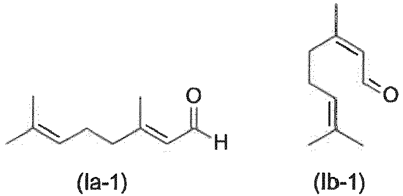 das optisch aktive Citronellal der Formel (III) einer Cyclisierung zu optisch aktivem Isopulegol unterzieht und das optisch aktive Isopulegol zu optisch aktivem Menthol hydriert.
 - Verfahren nach einem der Ansprüche 5 oder 6, wobei das erste Fluid eine nicht wasser-mischbare organische Flüssigkeit und das zweite Fluid eine wässrige Füssigkeit ist.
- Verfahren nach Anspruch 13 zur Herstellung eines β-Hydroxyketons, wobei das erste Fluid ein Dialkylketon umfasst und das zweite Fluid eine Formaldehyd-Quelle umfasst.
Applications Claiming Priority (2)
| Application Number | Priority Date | Filing Date | Title |
|---|---|---|---|
| EP18192755 | 2018-09-05 | ||
| PCT/EP2019/073472 WO2020048986A1 (de) | 2018-09-05 | 2019-09-03 | Reaktor zur durchführung einer reaktion zwischen zwei nicht mischbaren fluiden unterschiedlicher dichte |
Publications (2)
| Publication Number | Publication Date |
|---|---|
| EP3846927A1 EP3846927A1 (de) | 2021-07-14 |
| EP3846927B1 true EP3846927B1 (de) | 2022-11-23 |
Family
ID=63642509
Family Applications (1)
| Application Number | Title | Priority Date | Filing Date |
|---|---|---|---|
| EP19762155.0A Active EP3846927B1 (de) | 2018-09-05 | 2019-09-03 | Reaktor zur durchführung einer reaktion zwischen zwei nicht mischbaren fluiden unterschiedlicher dichte |
Country Status (6)
| Country | Link |
|---|---|
| US (1) | US11529607B2 (de) |
| EP (1) | EP3846927B1 (de) |
| CN (1) | CN112654421B (de) |
| ES (1) | ES2933963T3 (de) |
| MY (1) | MY206878A (de) |
| WO (1) | WO2020048986A1 (de) |
Families Citing this family (2)
| Publication number | Priority date | Publication date | Assignee | Title |
|---|---|---|---|---|
| CN113908733A (zh) * | 2021-10-18 | 2022-01-11 | 常州都铂高分子有限公司 | 一种可降解压敏胶生产装置及生产方法 |
| CN115041106B (zh) * | 2022-06-21 | 2023-11-07 | 湖北新轩宏新材料有限公司 | 一种制备三氯甲苯的反应器及制备方法 |
Family Cites Families (10)
| Publication number | Priority date | Publication date | Assignee | Title |
|---|---|---|---|---|
| US4000212A (en) * | 1971-07-29 | 1976-12-28 | Phillips Petroleum Company | Unitary acid-hydrocarbon reactor in hydrocarbon alkylation |
| DE10106482A1 (de) | 2001-02-13 | 2002-08-14 | Basf Ag | Hydroformylierung |
| DE60204873T2 (de) * | 2001-05-25 | 2006-05-18 | Bp Exploration Operating Co. Ltd. | Fischer-tropsch-syntheseverfahren |
| DE10206132A1 (de) | 2002-02-14 | 2003-08-21 | Basf Ag | Reaktorkaskade aus Haupt- und Nachreaktor |
| FR2850372B1 (fr) * | 2003-01-23 | 2006-06-09 | Inst Francais Du Petrole | Nouveau reacteur d'oxydation partielle |
| DE102004049631A1 (de) | 2004-10-11 | 2006-04-20 | Basf Ag | Verfahren zur Herstellung optisch aktiver Carbonylverbindungen |
| JP5479320B2 (ja) | 2007-04-25 | 2014-04-23 | ビーエーエスエフ ソシエタス・ヨーロピア | 光学活性カルボニル化合物の調製方法 |
| US20110137083A1 (en) * | 2008-05-27 | 2011-06-09 | Basf Se | Continuous method and reactor for hydrogenating organic compounds |
| DE102011082441A1 (de) * | 2011-09-09 | 2013-03-14 | Evonik Oxeno Gmbh | Strahlschlaufenreaktor mit Nanofiltration |
| EP3489213B1 (de) * | 2014-12-19 | 2021-04-28 | Basf Se | Zusammensetzung zur verwendung in einem verfahren zur herstellung optisch aktiver carbonylverbindungen |
-
2019
- 2019-09-03 ES ES19762155T patent/ES2933963T3/es active Active
- 2019-09-03 US US17/274,148 patent/US11529607B2/en active Active
- 2019-09-03 WO PCT/EP2019/073472 patent/WO2020048986A1/de not_active Ceased
- 2019-09-03 MY MYPI2021001128A patent/MY206878A/en unknown
- 2019-09-03 CN CN201980057894.9A patent/CN112654421B/zh active Active
- 2019-09-03 EP EP19762155.0A patent/EP3846927B1/de active Active
Also Published As
| Publication number | Publication date |
|---|---|
| MY206878A (en) | 2025-01-12 |
| EP3846927A1 (de) | 2021-07-14 |
| US11529607B2 (en) | 2022-12-20 |
| US20210275987A1 (en) | 2021-09-09 |
| CN112654421B (zh) | 2023-05-09 |
| ES2933963T3 (es) | 2023-02-15 |
| WO2020048986A1 (de) | 2020-03-12 |
| CN112654421A (zh) | 2021-04-13 |
Similar Documents
| Publication | Publication Date | Title |
|---|---|---|
| EP2318129B1 (de) | Parallelisierte strahlschlaufenreaktoren | |
| EP1114017B1 (de) | Verfahren zur herstellung von aldehyden und/oder alkoholen oder aminen | |
| EP1057524B1 (de) | Verfahren zur katalytischen Durchführung von Hydroformylierungen | |
| EP1586372B1 (de) | Alkoxylierungen in mikrostrukturierten Kapillarreaktoren | |
| EP3233778B1 (de) | Verfahren zur herstellung optisch aktiver carbonylverbindungen | |
| EP1318128B1 (de) | Verfahren zur selektiven Hydrierung von olefinisch ungesättigten Carbonylverbindungen | |
| WO2000030743A1 (de) | Reaktor zur kontinuierlichen durchführung von gas-flüssig-, flüssig-flüssig- oder gas-flüssig-fest-reaktionen | |
| EP1713762B1 (de) | Verfahren zur hydrocyanierung von butadien | |
| EP1231198B1 (de) | Hydroformylierung | |
| EP3394022A1 (de) | Zylindrischer reaktor und dessen verwendung zur kontinuierlichen hydroformylierung | |
| EP0947493A1 (de) | Verfahren zur selektiven Flüssigphasenhydrierung von alpha,beta-ungesättigten Carbonylverbindungen | |
| EP3846927A1 (de) | Reaktor zur durchführung einer reaktion zwischen zwei nicht mischbaren fluiden unterschiedlicher dichte | |
| KR101291015B1 (ko) | 올레핀의 하이드로포밀화 반응장치 및 이를 이용하는 하이드로포밀화 방법 | |
| EP3846929B1 (de) | Reaktor zur durchführung einer gas/flüssig-zweiphasigen hochdruckreaktion mit einem schäumenden medium | |
| EP3847151B1 (de) | Kontinuierliche herstellung einer optisch aktiven carbonylverbindung durch asymmetrische hydrierung | |
| EP3846931A1 (de) | Verfahren zur durchführung einer gas/flüssig-zweiphasigen hochdruckreaktion | |
| KR101298343B1 (ko) | 올레핀의 하이드로포밀화 반응장치 및 이를 이용하는 하이드로포밀화 방법 |
Legal Events
| Date | Code | Title | Description |
|---|---|---|---|
| STAA | Information on the status of an ep patent application or granted ep patent |
Free format text: STATUS: UNKNOWN |
|
| STAA | Information on the status of an ep patent application or granted ep patent |
Free format text: STATUS: THE INTERNATIONAL PUBLICATION HAS BEEN MADE |
|
| PUAI | Public reference made under article 153(3) epc to a published international application that has entered the european phase |
Free format text: ORIGINAL CODE: 0009012 |
|
| STAA | Information on the status of an ep patent application or granted ep patent |
Free format text: STATUS: REQUEST FOR EXAMINATION WAS MADE |
|
| 17P | Request for examination filed |
Effective date: 20210406 |
|
| AK | Designated contracting states |
Kind code of ref document: A1 Designated state(s): AL AT BE BG CH CY CZ DE DK EE ES FI FR GB GR HR HU IE IS IT LI LT LU LV MC MK MT NL NO PL PT RO RS SE SI SK SM TR |
|
| DAV | Request for validation of the european patent (deleted) | ||
| DAX | Request for extension of the european patent (deleted) | ||
| STAA | Information on the status of an ep patent application or granted ep patent |
Free format text: STATUS: EXAMINATION IS IN PROGRESS |
|
| 17Q | First examination report despatched |
Effective date: 20220222 |
|
| GRAP | Despatch of communication of intention to grant a patent |
Free format text: ORIGINAL CODE: EPIDOSNIGR1 |
|
| STAA | Information on the status of an ep patent application or granted ep patent |
Free format text: STATUS: GRANT OF PATENT IS INTENDED |
|
| INTG | Intention to grant announced |
Effective date: 20220623 |
|
| GRAS | Grant fee paid |
Free format text: ORIGINAL CODE: EPIDOSNIGR3 |
|
| GRAA | (expected) grant |
Free format text: ORIGINAL CODE: 0009210 |
|
| STAA | Information on the status of an ep patent application or granted ep patent |
Free format text: STATUS: THE PATENT HAS BEEN GRANTED |
|
| AK | Designated contracting states |
Kind code of ref document: B1 Designated state(s): AL AT BE BG CH CY CZ DE DK EE ES FI FR GB GR HR HU IE IS IT LI LT LU LV MC MK MT NL NO PL PT RO RS SE SI SK SM TR |
|
| REG | Reference to a national code |
Ref country code: GB Ref legal event code: FG4D Free format text: NOT ENGLISH |
|
| REG | Reference to a national code |
Ref country code: CH Ref legal event code: EP |
|
| REG | Reference to a national code |
Ref country code: AT Ref legal event code: REF Ref document number: 1532803 Country of ref document: AT Kind code of ref document: T Effective date: 20221215 Ref country code: DE Ref legal event code: R096 Ref document number: 502019006360 Country of ref document: DE |
|
| REG | Reference to a national code |
Ref country code: IE Ref legal event code: FG4D Free format text: LANGUAGE OF EP DOCUMENT: GERMAN |
|
| REG | Reference to a national code |
Ref country code: NL Ref legal event code: FP Ref country code: ES Ref legal event code: FG2A Ref document number: 2933963 Country of ref document: ES Kind code of ref document: T3 Effective date: 20230215 |
|
| REG | Reference to a national code |
Ref country code: LT Ref legal event code: MG9D |
|
| PG25 | Lapsed in a contracting state [announced via postgrant information from national office to epo] |
Ref country code: SE Free format text: LAPSE BECAUSE OF FAILURE TO SUBMIT A TRANSLATION OF THE DESCRIPTION OR TO PAY THE FEE WITHIN THE PRESCRIBED TIME-LIMIT Effective date: 20221123 Ref country code: PT Free format text: LAPSE BECAUSE OF FAILURE TO SUBMIT A TRANSLATION OF THE DESCRIPTION OR TO PAY THE FEE WITHIN THE PRESCRIBED TIME-LIMIT Effective date: 20230323 Ref country code: NO Free format text: LAPSE BECAUSE OF FAILURE TO SUBMIT A TRANSLATION OF THE DESCRIPTION OR TO PAY THE FEE WITHIN THE PRESCRIBED TIME-LIMIT Effective date: 20230223 Ref country code: LT Free format text: LAPSE BECAUSE OF FAILURE TO SUBMIT A TRANSLATION OF THE DESCRIPTION OR TO PAY THE FEE WITHIN THE PRESCRIBED TIME-LIMIT Effective date: 20221123 Ref country code: FI Free format text: LAPSE BECAUSE OF FAILURE TO SUBMIT A TRANSLATION OF THE DESCRIPTION OR TO PAY THE FEE WITHIN THE PRESCRIBED TIME-LIMIT Effective date: 20221123 |
|
| PG25 | Lapsed in a contracting state [announced via postgrant information from national office to epo] |
Ref country code: RS Free format text: LAPSE BECAUSE OF FAILURE TO SUBMIT A TRANSLATION OF THE DESCRIPTION OR TO PAY THE FEE WITHIN THE PRESCRIBED TIME-LIMIT Effective date: 20221123 Ref country code: PL Free format text: LAPSE BECAUSE OF FAILURE TO SUBMIT A TRANSLATION OF THE DESCRIPTION OR TO PAY THE FEE WITHIN THE PRESCRIBED TIME-LIMIT Effective date: 20221123 Ref country code: LV Free format text: LAPSE BECAUSE OF FAILURE TO SUBMIT A TRANSLATION OF THE DESCRIPTION OR TO PAY THE FEE WITHIN THE PRESCRIBED TIME-LIMIT Effective date: 20221123 Ref country code: IS Free format text: LAPSE BECAUSE OF FAILURE TO SUBMIT A TRANSLATION OF THE DESCRIPTION OR TO PAY THE FEE WITHIN THE PRESCRIBED TIME-LIMIT Effective date: 20230323 Ref country code: HR Free format text: LAPSE BECAUSE OF FAILURE TO SUBMIT A TRANSLATION OF THE DESCRIPTION OR TO PAY THE FEE WITHIN THE PRESCRIBED TIME-LIMIT Effective date: 20221123 Ref country code: GR Free format text: LAPSE BECAUSE OF FAILURE TO SUBMIT A TRANSLATION OF THE DESCRIPTION OR TO PAY THE FEE WITHIN THE PRESCRIBED TIME-LIMIT Effective date: 20230224 |
|
| P01 | Opt-out of the competence of the unified patent court (upc) registered |
Effective date: 20230331 |
|
| PG25 | Lapsed in a contracting state [announced via postgrant information from national office to epo] |
Ref country code: SM Free format text: LAPSE BECAUSE OF FAILURE TO SUBMIT A TRANSLATION OF THE DESCRIPTION OR TO PAY THE FEE WITHIN THE PRESCRIBED TIME-LIMIT Effective date: 20221123 Ref country code: RO Free format text: LAPSE BECAUSE OF FAILURE TO SUBMIT A TRANSLATION OF THE DESCRIPTION OR TO PAY THE FEE WITHIN THE PRESCRIBED TIME-LIMIT Effective date: 20221123 Ref country code: EE Free format text: LAPSE BECAUSE OF FAILURE TO SUBMIT A TRANSLATION OF THE DESCRIPTION OR TO PAY THE FEE WITHIN THE PRESCRIBED TIME-LIMIT Effective date: 20221123 Ref country code: DK Free format text: LAPSE BECAUSE OF FAILURE TO SUBMIT A TRANSLATION OF THE DESCRIPTION OR TO PAY THE FEE WITHIN THE PRESCRIBED TIME-LIMIT Effective date: 20221123 Ref country code: CZ Free format text: LAPSE BECAUSE OF FAILURE TO SUBMIT A TRANSLATION OF THE DESCRIPTION OR TO PAY THE FEE WITHIN THE PRESCRIBED TIME-LIMIT Effective date: 20221123 |
|
| REG | Reference to a national code |
Ref country code: DE Ref legal event code: R097 Ref document number: 502019006360 Country of ref document: DE |
|
| PG25 | Lapsed in a contracting state [announced via postgrant information from national office to epo] |
Ref country code: SK Free format text: LAPSE BECAUSE OF FAILURE TO SUBMIT A TRANSLATION OF THE DESCRIPTION OR TO PAY THE FEE WITHIN THE PRESCRIBED TIME-LIMIT Effective date: 20221123 Ref country code: AL Free format text: LAPSE BECAUSE OF FAILURE TO SUBMIT A TRANSLATION OF THE DESCRIPTION OR TO PAY THE FEE WITHIN THE PRESCRIBED TIME-LIMIT Effective date: 20221123 |
|
| PLBE | No opposition filed within time limit |
Free format text: ORIGINAL CODE: 0009261 |
|
| STAA | Information on the status of an ep patent application or granted ep patent |
Free format text: STATUS: NO OPPOSITION FILED WITHIN TIME LIMIT |
|
| 26N | No opposition filed |
Effective date: 20230824 |
|
| PG25 | Lapsed in a contracting state [announced via postgrant information from national office to epo] |
Ref country code: SI Free format text: LAPSE BECAUSE OF FAILURE TO SUBMIT A TRANSLATION OF THE DESCRIPTION OR TO PAY THE FEE WITHIN THE PRESCRIBED TIME-LIMIT Effective date: 20221123 |
|
| PG25 | Lapsed in a contracting state [announced via postgrant information from national office to epo] |
Ref country code: LU Free format text: LAPSE BECAUSE OF NON-PAYMENT OF DUE FEES Effective date: 20230903 |
|
| PG25 | Lapsed in a contracting state [announced via postgrant information from national office to epo] |
Ref country code: LU Free format text: LAPSE BECAUSE OF NON-PAYMENT OF DUE FEES Effective date: 20230903 Ref country code: MC Free format text: LAPSE BECAUSE OF FAILURE TO SUBMIT A TRANSLATION OF THE DESCRIPTION OR TO PAY THE FEE WITHIN THE PRESCRIBED TIME-LIMIT Effective date: 20221123 |
|
| REG | Reference to a national code |
Ref country code: IE Ref legal event code: MM4A |
|
| PG25 | Lapsed in a contracting state [announced via postgrant information from national office to epo] |
Ref country code: IE Free format text: LAPSE BECAUSE OF NON-PAYMENT OF DUE FEES Effective date: 20230903 |
|
| PG25 | Lapsed in a contracting state [announced via postgrant information from national office to epo] |
Ref country code: IE Free format text: LAPSE BECAUSE OF NON-PAYMENT OF DUE FEES Effective date: 20230903 |
|
| PG25 | Lapsed in a contracting state [announced via postgrant information from national office to epo] |
Ref country code: BG Free format text: LAPSE BECAUSE OF FAILURE TO SUBMIT A TRANSLATION OF THE DESCRIPTION OR TO PAY THE FEE WITHIN THE PRESCRIBED TIME-LIMIT Effective date: 20221123 |
|
| PG25 | Lapsed in a contracting state [announced via postgrant information from national office to epo] |
Ref country code: BG Free format text: LAPSE BECAUSE OF FAILURE TO SUBMIT A TRANSLATION OF THE DESCRIPTION OR TO PAY THE FEE WITHIN THE PRESCRIBED TIME-LIMIT Effective date: 20221123 |
|
| PG25 | Lapsed in a contracting state [announced via postgrant information from national office to epo] |
Ref country code: CY Free format text: LAPSE BECAUSE OF FAILURE TO SUBMIT A TRANSLATION OF THE DESCRIPTION OR TO PAY THE FEE WITHIN THE PRESCRIBED TIME-LIMIT; INVALID AB INITIO Effective date: 20190903 |
|
| PG25 | Lapsed in a contracting state [announced via postgrant information from national office to epo] |
Ref country code: HU Free format text: LAPSE BECAUSE OF FAILURE TO SUBMIT A TRANSLATION OF THE DESCRIPTION OR TO PAY THE FEE WITHIN THE PRESCRIBED TIME-LIMIT; INVALID AB INITIO Effective date: 20190903 |
|
| REG | Reference to a national code |
Ref country code: CH Ref legal event code: U11 Free format text: ST27 STATUS EVENT CODE: U-0-0-U10-U11 (AS PROVIDED BY THE NATIONAL OFFICE) Effective date: 20251001 |
|
| PGFP | Annual fee paid to national office [announced via postgrant information from national office to epo] |
Ref country code: DE Payment date: 20250926 Year of fee payment: 7 |
|
| PGFP | Annual fee paid to national office [announced via postgrant information from national office to epo] |
Ref country code: IT Payment date: 20250922 Year of fee payment: 7 Ref country code: NL Payment date: 20250925 Year of fee payment: 7 |
|
| PGFP | Annual fee paid to national office [announced via postgrant information from national office to epo] |
Ref country code: BE Payment date: 20250925 Year of fee payment: 7 Ref country code: GB Payment date: 20250923 Year of fee payment: 7 |
|
| PGFP | Annual fee paid to national office [announced via postgrant information from national office to epo] |
Ref country code: FR Payment date: 20250925 Year of fee payment: 7 |
|
| REG | Reference to a national code |
Ref country code: AT Ref legal event code: MM01 Ref document number: 1532803 Country of ref document: AT Kind code of ref document: T Effective date: 20240903 |
|
| PG25 | Lapsed in a contracting state [announced via postgrant information from national office to epo] |
Ref country code: TR Free format text: LAPSE BECAUSE OF FAILURE TO SUBMIT A TRANSLATION OF THE DESCRIPTION OR TO PAY THE FEE WITHIN THE PRESCRIBED TIME-LIMIT Effective date: 20221123 |
|
| PG25 | Lapsed in a contracting state [announced via postgrant information from national office to epo] |
Ref country code: AT Free format text: LAPSE BECAUSE OF NON-PAYMENT OF DUE FEES Effective date: 20240903 |
|
| PGFP | Annual fee paid to national office [announced via postgrant information from national office to epo] |
Ref country code: CH Payment date: 20251001 Year of fee payment: 7 |
|
| PGFP | Annual fee paid to national office [announced via postgrant information from national office to epo] |
Ref country code: ES Payment date: 20251015 Year of fee payment: 7 |
|
| PGFP | Annual fee paid to national office [announced via postgrant information from national office to epo] |
Ref country code: AT Payment date: 20260410 Year of fee payment: 5 |