EP3846956B1 - Wellenfederelement für vorrichtungen zum laden und befördern von stangen zu werkzeugmaschinen - Google Patents
Wellenfederelement für vorrichtungen zum laden und befördern von stangen zu werkzeugmaschinen Download PDFInfo
- Publication number
- EP3846956B1 EP3846956B1 EP19779168.4A EP19779168A EP3846956B1 EP 3846956 B1 EP3846956 B1 EP 3846956B1 EP 19779168 A EP19779168 A EP 19779168A EP 3846956 B1 EP3846956 B1 EP 3846956B1
- Authority
- EP
- European Patent Office
- Prior art keywords
- turns
- wave
- spring element
- diameter
- bush means
- Prior art date
- Legal status (The legal status is an assumption and is not a legal conclusion. Google has not performed a legal analysis and makes no representation as to the accuracy of the status listed.)
- Active
Links
Images


Classifications
-
- B—PERFORMING OPERATIONS; TRANSPORTING
- B23—MACHINE TOOLS; METAL-WORKING NOT OTHERWISE PROVIDED FOR
- B23B—TURNING; BORING
- B23B13/00—Arrangements for automatically conveying or chucking or guiding stock
- B23B13/08—Arrangements for reducing vibrations in feeding-passages or for damping noise
Definitions
- the present invention relates to a wave-spring element for a loader-apparatus for loading bars which must be fed to a machine tool, for example a single or multispindle lathe.
- the wave-spring element serves to contain and guide a bar during its rotation and advancement towards the machine tool and acts to dampen the flexural vibrations to which the bar is subjected during its rotation.
- loading apparatuses are used for automatic bar feeding.
- These loading apparatuses have a support drum and special containment and guide devices for the bars themselves.
- the bars that are fed to the lathe, during processing, are rotated around their longitudinal axis.
- the bars especially if slender, that is thin, i.e. having a very small cross-section in relation to their longitudinal length, are subject to intense stresses and flexural vibrations due to the centrifugal effect.
- the aforementioned containment and guide devices can have helical springs which receive the bar to be worked inside to contain and guide it so as to damp its flexural vibrations.
- Such springs are composed by a plurality of turns which can have different diameters in different areas, and which follow one another so as to give the spring itself a side profile, with narrow-diameter zones - intended to come into contact directly with the bar received inside them - and areas of greater diameter, intended to be separated and not in contact with the surface of the bar.
- a spring element for guiding pipes is known from SU617172.
- An object of the present invention is to improve the devices for guiding and damping the flexural vibrations of the bars within bar loading apparatuses for lathes or other machine tools.
- Another object is to provide a structurally and functionally simplified solution for damping the flexural vibrations of the bars within the loading apparatus for machine tools.
- Another object is to provide an affordable wave-spring element but highly capable of preserving the bars from any type of damage.
- a method is also provided for producing the aforementioned wave-spring element as specified in claim 8.
- the wave-spring element according to the invention is able to effectively carry out its function as a damper-element of flexural vibrations while preserving the surface of the bars from undesired damage caused by relative sliding with the turns that make up the wave-spring element itself.
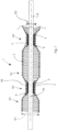
- a wave-spring element 1 according to the invention is described below, suitable for a bar loader apparatus arranged to feed the bars themselves to a machine tool, such as for example a mono or multi-spindle-lathe.
- the wave-spring element 1 comprises a plurality of turn elements 2 arranged one adjacent to the other.
- the turn elements 2 have different diameters and are grouped in first groups G1 of turn elements with a larger diameter D1 and second groups G2 of turn elements with a smaller diameter D2.
- the turn elements 2 are made of curved metal wire according to the desired helical path.
- Intermediate turns 2' placed between each first group G1 and the second adjacent group G2 are also provided, these intermediate turns 2' having a variable diameter ranging from the aforementioned diameter D1 to the diameter D2. Substantially, the intermediate turns 2' act as a gradual connection between the groups G1 and the groups G2 and contribute to give the wave-spring element 1 the sinusoidal or wavy shape.
- first groups G1 and the second groups G2 alternate one after the other along a longitudinal axis AL and between each first G1 and each second group G2 the aforesaid intermediate turns 2' with variable diameter are interposed.
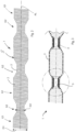
- the first groups G1 and the second groups G2, together with the intermediate turns 2' alternate so as to define, for the wave-spring element 1, a surface S having a sinusoidal profile, i.e. wavy. For this reason, it can be assumed that the wave-spring element 1 develops with a "sea wave" shape.
- the wave-spring element 1 thus defined is suitable to contain and guide a bar B, so as to damp the flexural vibrations to which the same bar B is subjected during its rotation.
- the wave-spring element 1 according to the invention is also provided with one or more bush or sleeve means, each one arranged inside a respective second group G2 of turns with a smaller diameter D2.
- the bush means 3 are configured to come into contact with, and receive inside, respective portions of the bar B to avoid contact with, and avoid the sliding with respect to, all the turns which are included in the wave-spring element 1. It is possible to provide any number of bush means 3 distributed along the longitudinal axis AL and spaced apart from one another by an amount appropriately chosen in relation to the diameter of the bar B to be supported and based on the thickness of the metal wire of the turns.
- the bush means 3 comprises a tubular element 3A having a cylindrical portion C on which the turn elements 2 of a respective second group G2 of turns with smaller diameter D2 are wound.
- the bush means 3 are provided with widened edge portions 8 at each of the two ends E1, E2 of a tubular element 3A.
- the aforesaid widened edge portions 8 are configured to couple externally with the inner surface of intermediate turns 2' having a larger diameter than the diameter D2 and placed at the ends of the respective second group G2.
- the widened edge portions 8 constrain, by means of a shape coupling, the bush means 3 to the wave-spring element 1.
- the flared shape of the ends of the bush means 3 causes the latter to remain stuck stably in the plurality of turns of variable diameter which make up the wave-spring element 1.
- the widened edge portions 8 have internally a truncated cone-shaped surface diverging towards the outside to favour the advancement of the bar B and to promote its insertion inside the respective bush means 3.
- the turns 2 with smaller diameter D2 of each second group G2 are wound tightly, and therefore tight, on the respective tubular elements 3A.
- the tight winding of these turns on the tubular 3A elements makes their position stable without risk of separation.
- the aforesaid turns 2 with a smaller diameter D2 of each second group G2 can be glued or welded or are connected through melting to the respective tubular elements 3A.
- the wave-spring element 1 rotates together with the bar B contained therein. There is therefore no relative rotation of the bar B with respect to the bush means 3.
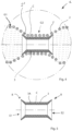
- recess housing seats 21 are obtained extending sinusoidally around the longitudinal axis AL and shaped to house the respective turns 2 and keep them in a firm position with respect to said bush means 3.
- the corrugated profile or in any case provided with housing seats of the external surface 20, which conforms to the wavy profile of the sequence of turns 2, ensures that there are no relative displacements of the bush means 3 with respect to the turns 2 themselves.
- the bush means 3 comprise an annular element 3B located internally to the respective tubular element 3A, rotatable with respect to the latter.
- annular element 3B and the respective tubular element 3A together define a bush unit 3 or sliding bearing unit 3.
- the annular element 3B is rotatable, together with the bar B, around the longitudinal axis AL and relative to the tubular element 3A which instead, during operation, can remain in a stationary position together with the plurality of turns 2.
- At least the turns 2 of the first G1 groups are made of plasticized metal wire or covered with a layer of material suitable for not scratching or damaging the bars B.
- These housing seats 21 with a recess extend sinusoidally about the longitudinal axis AL and are shaped to house the respective turns 2 and keep them in a fixed position with respect to said bush means 3.
- the corrugated profile, or in any case provided with recessed areas of the external surface 20 of the bush means 3, conforming to the corrugated profile of the sequence of turns 2 ensures that there are no relative displacements of the bush means 3 compared to the same turns 2.
- the wave-spring element 1 in the various versions just described, can be made by a method that includes the following steps:
- the described wave-spring element 1 although structurally and functionally simplified and therefore also affordable and simple to implement, effectively performs its function as a damper for the flexural vibrations of the bars while at the same time preserving the bars from any type of damages (due for example due to the relative sliding with the turns), owing to the presence of the bush means 3.
- the bar B is in contact, on several zones distributed along the longitudinal axis AL, with the cylindrical internal surfaces of the bush means 3, which being smooth and not presenting peak and valley areas (as instead would occur with the contact direct with the turns) they do not exert localized pressures and are not able to scratch the surface of the bar B.
- any component forming the wave-spring element 1 according to the invention can be replaced with other equivalents in structural and functional terms, and the materials, insofar as they are compatible with the specific use for which they are intended, can be suitably chosen according to the requirements and the available state of art.
Landscapes
- Engineering & Computer Science (AREA)
- Mechanical Engineering (AREA)
- Springs (AREA)
Claims (8)
- Wellenfederelement für eine Einrichtung zum Laden von Stangen, umfassend eine Vielzahl von Windungselementen (2), die angrenzend aneinander angeordnet sind, wobei die Vielzahl von Windungselementen (2) durch erste Gruppen (G1) von Windungselementen mit einem größeren Durchmesser (D1), und zweite Gruppen (G2) von Windungselementen mit einem geringeren Durchmesser (D2) definiert sind, wobei die ersten Gruppen (G1) und die zweiten Gruppen (G2) einander entlang einer Längsachse (AL) abwechseln, um eine Oberfläche (S) zu definieren, die ein Sinusprofil aufweist, wobei die Vielzahl von Windungselementen (2) konfiguriert sind, um eine Stange (B) zu enthalten und zu einem Maschinenwerkzeug zu führen, wie eine Drehmaschine, und zum Dämpfen der Biegeschwingungen, welchen die Stange (B) bei deren Drehung ausgesetzt ist, wobei weiter ein Buchsenmittel (3) bereitgestellt ist, das innerhalb jeder zweiten Gruppe (G2) von Windungen angeordnet ist, die einen geringeren Durchmesser (D2) aufweisen, wobei die Buchsenmittel (3) konfiguriert sind, um in Kontakt mit jeweiligen Abschnitten der Stange (B) zu treten, und diese innen aufzunehmen, um deren Kontakt mit den Windungen (2) zu vermeiden, und in Bezug dazu zu gleiten,
wobei das Wellenfederelement dadurch gekennzeichnet ist, dass auf einer Außenoberfläche (20) der Buchsenmittel (3) Aussparungs-Einhausungs-Sitze (21) erhalten werden, die sich sinusförmig erstrecken, und zum Einhausen der jeweiligen Windungen (2) und Halten der Windungen in einer stationären Position in Bezug auf die Buchsenmittel (3) geformt sind. - Wellenfederelement nach Anspruch 1, wobei die Buchsenmittel (3) ein röhrenförmiges Element (3A) umfassen, das einen zylindrischen Abschnitt (C) aufweist, auf den die Windungselemente (2) von einer jeweiligen zweiten Gruppe (G2) von Windungen mit einem geringeren Durchmesser (D2) gewickelt sind, und wobei zwischen jeder ersten Gruppe (G1) und einer angrenzenden zweiten Gruppe (G2) Zwischenwindungselemente (2') bereitgestellt sind, die einen Durchmesser aufweisen, der zwischen dem ersten Durchmesser (D1) und dem zweiten Durchmesser (D2) liegt.
- Wellenfederelement nach Anspruch 2, wobei die Buchsenmittel (3) mit erweiterten Kantenabschnitten (8) an jedem der beiden Enden (E1,E2) des röhrenförmigen Elements (3A) bereitgestellt sind, wobei die erweiterten Kantenabschnitte (8) konfiguriert sind, um außen mit der Innenoberfläche der Windungen (2') mit einem größeren Durchmesser als dem Durchmesser (D2) gekoppelt zu werden, und an den Enden der jeweiligen zweiten Gruppe (G2) platziert sind, um die Buchsenmittel (3) in einer formschlüssigen Weise an das Wellenfederelement (1) zu binden.
- Wellenfederelement nach Anspruch 3, wobei der erweiterte Kantenabschnitt (8) innen eine kegelstumpfförmige Oberfläche aufweist, die nach außen divergiert, um das Vorankommen der Stange (B) zu fördern, und deren Einführung in die jeweiligen Buchsenmittel (3) zu unterstützen.
- Wellenfederelement nach einem der Ansprüche 2 bis 4, wobei die Buchsenmittel (3) jeweils ein ringförmiges Element (3B) umfassen, das innerhalb des jeweiligen röhrenförmigen Elements (3A) platziert ist, und in Bezug auf letzteres drehend beweglich ist, wobei das ringförmige Element (3B) und das röhrenförmige Element (3A) gemeinsam eine Buchseneinheit oder ein Gleitlager definieren, wobei das ringförmige Element (3B) gemeinsam mit der Stange (B) um die Längsachse in Bezug auf das röhrenförmige Element (3A) drehbar ist, welches während des Vorgangs gemeinsam mit der Vielzahl von Drehelementen (2) in einer stationären Position verbleiben kann.
- Wellenfederelement nach einem vorstehenden Anspruch, wobei mindestens die Windungen (2) der ersten Gruppen (G1) aus einem Metalldraht gefertigt sind, welcher plastifiziert, oder mit einer Schicht aus einem Material beschichtet ist, das geeignet ist, um die Stangen (B) nicht zu zerkratzen oder zu beschädigen.
- Wellenfederelement nach einem vorstehenden Anspruch, wobei die Windungen (2) aus gekrümmtem Metalldraht gefertigt sind, und die Buchsenmittel (3) in einer gewünschten Anzahl entlang der Längsachse (AL) verteilt sind, und voneinander durch eine Menge beabstandet sind, die in Bezug auf den Durchmesser der Stange (B), die zu tragen ist, und auf der Grundlage der Dicke des Metalldrahtes ausgewählt wird.
- Verfahren zur Herstellung eines Wellenfederelements nach Anspruch 1, die folgenden Schritte umfassend:- a) Wickeln eines ersten Abschnitts eines Metalldrahts zum Erzeugen einer ersten Gruppe (G1) von Windungen (2), die aneinander angrenzen und einen ersten Durchmesser (D1) aufweisen,- b) Wickeln eines zweiten Abschnitts, nach dem ersten Abschnitt, des Metalldrahts um Buchsenmittel (3) herum, um eine zweite Gruppe (G2) von Windungen (2) zu erzeugen, die aneinander angrenzend sind, und einen zweiten Durchmesser (D2) aufweisen, der geringer als der erste Durchmesser (D1) ist, wobei die Windungen (2) der zweiten Gruppe (G2) um die Buchsenmittel (3) herum gestrafft sind, um letztere in einer stabilen Position zu halten,- abwechselnd Wiederholen der Schritte a) und b), um ein Federelement (1) mit einem Sinusprofil zu erhalten, das sich entlang einer Längsachse (AL) erstreckt, bis eine gewünschte Länge erreicht wird,wobei das Verfahren dadurch gekennzeichnet ist, dass es weiter die folgenden Schritte umfasst:- Erhalten von Aussparungs-Einhausungs-Sitzen (21) auf einer Außenoberfläche (20) des röhrenförmigen Elements (3A) der Buchsenmittel (3), wobei sich die Aussparungs-Einhausungs-Sitze (21) sinusförmig um die Längsachse (AL) herum erstrecken, und geformt sind, um die jeweiligen Windungen (2) einzuhausen, und die Windungen (2) in einer festen Position in Bezug auf die Buchsenmittel (3) zu halten.
Applications Claiming Priority (2)
| Application Number | Priority Date | Filing Date | Title |
|---|---|---|---|
| IT201800008314 | 2018-09-03 | ||
| PCT/IB2019/057387 WO2020049439A1 (en) | 2018-09-03 | 2019-09-02 | Wave-spring element for apparatuses for loading and advancing bars to machine tools |
Publications (2)
| Publication Number | Publication Date |
|---|---|
| EP3846956A1 EP3846956A1 (de) | 2021-07-14 |
| EP3846956B1 true EP3846956B1 (de) | 2023-11-08 |
Family
ID=64316815
Family Applications (1)
| Application Number | Title | Priority Date | Filing Date |
|---|---|---|---|
| EP19779168.4A Active EP3846956B1 (de) | 2018-09-03 | 2019-09-02 | Wellenfederelement für vorrichtungen zum laden und befördern von stangen zu werkzeugmaschinen |
Country Status (3)
| Country | Link |
|---|---|
| EP (1) | EP3846956B1 (de) |
| ES (1) | ES2968848T3 (de) |
| WO (1) | WO2020049439A1 (de) |
Citations (1)
| Publication number | Priority date | Publication date | Assignee | Title |
|---|---|---|---|---|
| EP0370240B1 (de) * | 1988-11-21 | 1994-01-05 | CUCCHI GIOVANNI & C. S.r.l. | Stangenvorschub-Vorrichtung |
Family Cites Families (2)
| Publication number | Priority date | Publication date | Assignee | Title |
|---|---|---|---|---|
| US3930568A (en) * | 1973-05-29 | 1976-01-06 | Bti Company | Bar stock silencer tube |
| SU617172A2 (ru) * | 1977-03-04 | 1978-07-30 | Ростовский-На-Дону Институт Сельскохозяйственного Машиностроения | Направл юща труба к токарно-револьверным станкам и автоматам |
-
2019
- 2019-09-02 EP EP19779168.4A patent/EP3846956B1/de active Active
- 2019-09-02 WO PCT/IB2019/057387 patent/WO2020049439A1/en not_active Ceased
- 2019-09-02 ES ES19779168T patent/ES2968848T3/es active Active
Patent Citations (1)
| Publication number | Priority date | Publication date | Assignee | Title |
|---|---|---|---|---|
| EP0370240B1 (de) * | 1988-11-21 | 1994-01-05 | CUCCHI GIOVANNI & C. S.r.l. | Stangenvorschub-Vorrichtung |
Also Published As
| Publication number | Publication date |
|---|---|
| ES2968848T3 (es) | 2024-05-14 |
| WO2020049439A1 (en) | 2020-03-12 |
| EP3846956A1 (de) | 2021-07-14 |
Similar Documents
| Publication | Publication Date | Title |
|---|---|---|
| US9718139B2 (en) | Tool for grinding toothed workpieces having collision contours | |
| CN103495755A (zh) | 一种不通孔薄壁套筒类零件外壁加工夹具及其使用方法 | |
| CN110064790B (zh) | 一种卡盘扩张式金属硬管旋转切割机 | |
| CA2080463A1 (en) | Method of manufacturing a coil of a continuous flexible object and enveloping the coil to form a parcel | |
| EP3846956A1 (de) | Wellenfederelement für vorrichtungen zum laden und befördern von stangen zu werkzeugmaschinen | |
| CN107020524A (zh) | 一种夹持薄壁套类零件的工装 | |
| ITBO20080240A1 (it) | Dispositivo rotante di centraggio per il trasferimento guidato di barre da un caricatore ad un tornio | |
| KR20160143417A (ko) | 봉재 지지어댑터 | |
| KR20160076259A (ko) | 공작기계 | |
| RU153048U1 (ru) | Токарный патрон для закрепления ракетного двигателя | |
| JP5445544B2 (ja) | 複合旋盤及び複合加工方法 | |
| JP6568941B2 (ja) | チャック装置 | |
| CN109483328B (zh) | 加工机构及具有其的机加工装置 | |
| RU2678721C2 (ru) | Конструкция механизма поддержки прутка с демпфирующими втулками | |
| KR102177689B1 (ko) | 샤프트 가공 장치 | |
| US1786876A (en) | Feeding device for machine tools | |
| US5193826A (en) | Face plate adapter for a machine tool | |
| CA2882322C (en) | Improved spindle liner component for turning machines | |
| US1020460A (en) | Reel for metal-working machines. | |
| US1413680A (en) | Chuck collet | |
| CN210676994U (zh) | 一种数控自动转台 | |
| US3933062A (en) | Sound deadening means for screw machine | |
| CN114260736B (zh) | 薄壁台阶盖板用开口套及薄壁台阶盖板加工方法 | |
| SU808213A1 (ru) | Патрон дл обработки тонкостенныхдЕТАлЕй | |
| US3935763A (en) | Machining vulcanized fibre |
Legal Events
| Date | Code | Title | Description |
|---|---|---|---|
| STAA | Information on the status of an ep patent application or granted ep patent |
Free format text: STATUS: UNKNOWN |
|
| STAA | Information on the status of an ep patent application or granted ep patent |
Free format text: STATUS: THE INTERNATIONAL PUBLICATION HAS BEEN MADE |
|
| PUAI | Public reference made under article 153(3) epc to a published international application that has entered the european phase |
Free format text: ORIGINAL CODE: 0009012 |
|
| STAA | Information on the status of an ep patent application or granted ep patent |
Free format text: STATUS: REQUEST FOR EXAMINATION WAS MADE |
|
| 17P | Request for examination filed |
Effective date: 20210401 |
|
| AK | Designated contracting states |
Kind code of ref document: A1 Designated state(s): AL AT BE BG CH CY CZ DE DK EE ES FI FR GB GR HR HU IE IS IT LI LT LU LV MC MK MT NL NO PL PT RO RS SE SI SK SM TR |
|
| DAV | Request for validation of the european patent (deleted) | ||
| DAX | Request for extension of the european patent (deleted) | ||
| RAP3 | Party data changed (applicant data changed or rights of an application transferred) |
Owner name: CUCCHI GIOVANNI & C. S.R.L. |
|
| GRAP | Despatch of communication of intention to grant a patent |
Free format text: ORIGINAL CODE: EPIDOSNIGR1 |
|
| STAA | Information on the status of an ep patent application or granted ep patent |
Free format text: STATUS: GRANT OF PATENT IS INTENDED |
|
| INTG | Intention to grant announced |
Effective date: 20230413 |
|
| P01 | Opt-out of the competence of the unified patent court (upc) registered |
Effective date: 20230608 |
|
| GRAS | Grant fee paid |
Free format text: ORIGINAL CODE: EPIDOSNIGR3 |
|
| RIN1 | Information on inventor provided before grant (corrected) |
Inventor name: CUCCHI, CESARE |
|
| GRAA | (expected) grant |
Free format text: ORIGINAL CODE: 0009210 |
|
| STAA | Information on the status of an ep patent application or granted ep patent |
Free format text: STATUS: THE PATENT HAS BEEN GRANTED |
|
| AK | Designated contracting states |
Kind code of ref document: B1 Designated state(s): AL AT BE BG CH CY CZ DE DK EE ES FI FR GB GR HR HU IE IS IT LI LT LU LV MC MK MT NL NO PL PT RO RS SE SI SK SM TR |
|
| REG | Reference to a national code |
Ref country code: GB Ref legal event code: FG4D |
|
| REG | Reference to a national code |
Ref country code: CH Ref legal event code: EP |
|
| REG | Reference to a national code |
Ref country code: DE Ref legal event code: R096 Ref document number: 602019041127 Country of ref document: DE |
|
| REG | Reference to a national code |
Ref country code: IE Ref legal event code: FG4D |
|
| REG | Reference to a national code |
Ref country code: LT Ref legal event code: MG9D |
|
| REG | Reference to a national code |
Ref country code: NL Ref legal event code: MP Effective date: 20231108 |
|
| PG25 | Lapsed in a contracting state [announced via postgrant information from national office to epo] |
Ref country code: GR Free format text: LAPSE BECAUSE OF FAILURE TO SUBMIT A TRANSLATION OF THE DESCRIPTION OR TO PAY THE FEE WITHIN THE PRESCRIBED TIME-LIMIT Effective date: 20240209 |
|
| PG25 | Lapsed in a contracting state [announced via postgrant information from national office to epo] |
Ref country code: IS Free format text: LAPSE BECAUSE OF FAILURE TO SUBMIT A TRANSLATION OF THE DESCRIPTION OR TO PAY THE FEE WITHIN THE PRESCRIBED TIME-LIMIT Effective date: 20240308 |
|
| PG25 | Lapsed in a contracting state [announced via postgrant information from national office to epo] |
Ref country code: LT Free format text: LAPSE BECAUSE OF FAILURE TO SUBMIT A TRANSLATION OF THE DESCRIPTION OR TO PAY THE FEE WITHIN THE PRESCRIBED TIME-LIMIT Effective date: 20231108 |
|
| REG | Reference to a national code |
Ref country code: AT Ref legal event code: MK05 Ref document number: 1629183 Country of ref document: AT Kind code of ref document: T Effective date: 20231108 |
|
| PG25 | Lapsed in a contracting state [announced via postgrant information from national office to epo] |
Ref country code: NL Free format text: LAPSE BECAUSE OF FAILURE TO SUBMIT A TRANSLATION OF THE DESCRIPTION OR TO PAY THE FEE WITHIN THE PRESCRIBED TIME-LIMIT Effective date: 20231108 |
|
| PG25 | Lapsed in a contracting state [announced via postgrant information from national office to epo] |
Ref country code: AT Free format text: LAPSE BECAUSE OF FAILURE TO SUBMIT A TRANSLATION OF THE DESCRIPTION OR TO PAY THE FEE WITHIN THE PRESCRIBED TIME-LIMIT Effective date: 20231108 |
|
| PG25 | Lapsed in a contracting state [announced via postgrant information from national office to epo] |
Ref country code: NL Free format text: LAPSE BECAUSE OF FAILURE TO SUBMIT A TRANSLATION OF THE DESCRIPTION OR TO PAY THE FEE WITHIN THE PRESCRIBED TIME-LIMIT Effective date: 20231108 Ref country code: LT Free format text: LAPSE BECAUSE OF FAILURE TO SUBMIT A TRANSLATION OF THE DESCRIPTION OR TO PAY THE FEE WITHIN THE PRESCRIBED TIME-LIMIT Effective date: 20231108 Ref country code: IS Free format text: LAPSE BECAUSE OF FAILURE TO SUBMIT A TRANSLATION OF THE DESCRIPTION OR TO PAY THE FEE WITHIN THE PRESCRIBED TIME-LIMIT Effective date: 20240308 Ref country code: GR Free format text: LAPSE BECAUSE OF FAILURE TO SUBMIT A TRANSLATION OF THE DESCRIPTION OR TO PAY THE FEE WITHIN THE PRESCRIBED TIME-LIMIT Effective date: 20240209 Ref country code: BG Free format text: LAPSE BECAUSE OF FAILURE TO SUBMIT A TRANSLATION OF THE DESCRIPTION OR TO PAY THE FEE WITHIN THE PRESCRIBED TIME-LIMIT Effective date: 20240208 Ref country code: AT Free format text: LAPSE BECAUSE OF FAILURE TO SUBMIT A TRANSLATION OF THE DESCRIPTION OR TO PAY THE FEE WITHIN THE PRESCRIBED TIME-LIMIT Effective date: 20231108 Ref country code: PT Free format text: LAPSE BECAUSE OF FAILURE TO SUBMIT A TRANSLATION OF THE DESCRIPTION OR TO PAY THE FEE WITHIN THE PRESCRIBED TIME-LIMIT Effective date: 20240308 |
|
| REG | Reference to a national code |
Ref country code: ES Ref legal event code: FG2A Ref document number: 2968848 Country of ref document: ES Kind code of ref document: T3 Effective date: 20240514 |
|
| PG25 | Lapsed in a contracting state [announced via postgrant information from national office to epo] |
Ref country code: SE Free format text: LAPSE BECAUSE OF FAILURE TO SUBMIT A TRANSLATION OF THE DESCRIPTION OR TO PAY THE FEE WITHIN THE PRESCRIBED TIME-LIMIT Effective date: 20231108 Ref country code: RS Free format text: LAPSE BECAUSE OF FAILURE TO SUBMIT A TRANSLATION OF THE DESCRIPTION OR TO PAY THE FEE WITHIN THE PRESCRIBED TIME-LIMIT Effective date: 20231108 Ref country code: PL Free format text: LAPSE BECAUSE OF FAILURE TO SUBMIT A TRANSLATION OF THE DESCRIPTION OR TO PAY THE FEE WITHIN THE PRESCRIBED TIME-LIMIT Effective date: 20231108 Ref country code: NO Free format text: LAPSE BECAUSE OF FAILURE TO SUBMIT A TRANSLATION OF THE DESCRIPTION OR TO PAY THE FEE WITHIN THE PRESCRIBED TIME-LIMIT Effective date: 20240208 Ref country code: LV Free format text: LAPSE BECAUSE OF FAILURE TO SUBMIT A TRANSLATION OF THE DESCRIPTION OR TO PAY THE FEE WITHIN THE PRESCRIBED TIME-LIMIT Effective date: 20231108 Ref country code: HR Free format text: LAPSE BECAUSE OF FAILURE TO SUBMIT A TRANSLATION OF THE DESCRIPTION OR TO PAY THE FEE WITHIN THE PRESCRIBED TIME-LIMIT Effective date: 20231108 |
|
| PG25 | Lapsed in a contracting state [announced via postgrant information from national office to epo] |
Ref country code: DK Free format text: LAPSE BECAUSE OF FAILURE TO SUBMIT A TRANSLATION OF THE DESCRIPTION OR TO PAY THE FEE WITHIN THE PRESCRIBED TIME-LIMIT Effective date: 20231108 |
|
| PG25 | Lapsed in a contracting state [announced via postgrant information from national office to epo] |
Ref country code: CZ Free format text: LAPSE BECAUSE OF FAILURE TO SUBMIT A TRANSLATION OF THE DESCRIPTION OR TO PAY THE FEE WITHIN THE PRESCRIBED TIME-LIMIT Effective date: 20231108 |
|
| PG25 | Lapsed in a contracting state [announced via postgrant information from national office to epo] |
Ref country code: SK Free format text: LAPSE BECAUSE OF FAILURE TO SUBMIT A TRANSLATION OF THE DESCRIPTION OR TO PAY THE FEE WITHIN THE PRESCRIBED TIME-LIMIT Effective date: 20231108 |
|
| PG25 | Lapsed in a contracting state [announced via postgrant information from national office to epo] |
Ref country code: SM Free format text: LAPSE BECAUSE OF FAILURE TO SUBMIT A TRANSLATION OF THE DESCRIPTION OR TO PAY THE FEE WITHIN THE PRESCRIBED TIME-LIMIT Effective date: 20231108 Ref country code: SK Free format text: LAPSE BECAUSE OF FAILURE TO SUBMIT A TRANSLATION OF THE DESCRIPTION OR TO PAY THE FEE WITHIN THE PRESCRIBED TIME-LIMIT Effective date: 20231108 Ref country code: RO Free format text: LAPSE BECAUSE OF FAILURE TO SUBMIT A TRANSLATION OF THE DESCRIPTION OR TO PAY THE FEE WITHIN THE PRESCRIBED TIME-LIMIT Effective date: 20231108 Ref country code: EE Free format text: LAPSE BECAUSE OF FAILURE TO SUBMIT A TRANSLATION OF THE DESCRIPTION OR TO PAY THE FEE WITHIN THE PRESCRIBED TIME-LIMIT Effective date: 20231108 Ref country code: DK Free format text: LAPSE BECAUSE OF FAILURE TO SUBMIT A TRANSLATION OF THE DESCRIPTION OR TO PAY THE FEE WITHIN THE PRESCRIBED TIME-LIMIT Effective date: 20231108 Ref country code: CZ Free format text: LAPSE BECAUSE OF FAILURE TO SUBMIT A TRANSLATION OF THE DESCRIPTION OR TO PAY THE FEE WITHIN THE PRESCRIBED TIME-LIMIT Effective date: 20231108 |
|
| REG | Reference to a national code |
Ref country code: DE Ref legal event code: R097 Ref document number: 602019041127 Country of ref document: DE |
|
| PLBE | No opposition filed within time limit |
Free format text: ORIGINAL CODE: 0009261 |
|
| STAA | Information on the status of an ep patent application or granted ep patent |
Free format text: STATUS: NO OPPOSITION FILED WITHIN TIME LIMIT |
|
| PGFP | Annual fee paid to national office [announced via postgrant information from national office to epo] |
Ref country code: GB Payment date: 20240927 Year of fee payment: 6 |
|
| 26N | No opposition filed |
Effective date: 20240809 |
|
| PG25 | Lapsed in a contracting state [announced via postgrant information from national office to epo] |
Ref country code: SI Free format text: LAPSE BECAUSE OF FAILURE TO SUBMIT A TRANSLATION OF THE DESCRIPTION OR TO PAY THE FEE WITHIN THE PRESCRIBED TIME-LIMIT Effective date: 20231108 |
|
| PG25 | Lapsed in a contracting state [announced via postgrant information from national office to epo] |
Ref country code: SI Free format text: LAPSE BECAUSE OF FAILURE TO SUBMIT A TRANSLATION OF THE DESCRIPTION OR TO PAY THE FEE WITHIN THE PRESCRIBED TIME-LIMIT Effective date: 20231108 |
|
| PG25 | Lapsed in a contracting state [announced via postgrant information from national office to epo] |
Ref country code: MC Free format text: LAPSE BECAUSE OF FAILURE TO SUBMIT A TRANSLATION OF THE DESCRIPTION OR TO PAY THE FEE WITHIN THE PRESCRIBED TIME-LIMIT Effective date: 20231108 |
|
| REG | Reference to a national code |
Ref country code: CH Ref legal event code: PL |
|
| PG25 | Lapsed in a contracting state [announced via postgrant information from national office to epo] |
Ref country code: LU Free format text: LAPSE BECAUSE OF NON-PAYMENT OF DUE FEES Effective date: 20240902 |
|
| REG | Reference to a national code |
Ref country code: BE Ref legal event code: MM Effective date: 20240930 |
|
| PG25 | Lapsed in a contracting state [announced via postgrant information from national office to epo] |
Ref country code: BE Free format text: LAPSE BECAUSE OF NON-PAYMENT OF DUE FEES Effective date: 20240930 |
|
| PG25 | Lapsed in a contracting state [announced via postgrant information from national office to epo] |
Ref country code: CH Free format text: LAPSE BECAUSE OF NON-PAYMENT OF DUE FEES Effective date: 20240930 |
|
| PG25 | Lapsed in a contracting state [announced via postgrant information from national office to epo] |
Ref country code: IE Free format text: LAPSE BECAUSE OF NON-PAYMENT OF DUE FEES Effective date: 20240902 |
|
| PG25 | Lapsed in a contracting state [announced via postgrant information from national office to epo] |
Ref country code: FI Free format text: LAPSE BECAUSE OF FAILURE TO SUBMIT A TRANSLATION OF THE DESCRIPTION OR TO PAY THE FEE WITHIN THE PRESCRIBED TIME-LIMIT Effective date: 20231108 |
|
| PGFP | Annual fee paid to national office [announced via postgrant information from national office to epo] |
Ref country code: DE Payment date: 20250929 Year of fee payment: 7 |
|
| PGFP | Annual fee paid to national office [announced via postgrant information from national office to epo] |
Ref country code: IT Payment date: 20250924 Year of fee payment: 7 |
|
| PGFP | Annual fee paid to national office [announced via postgrant information from national office to epo] |
Ref country code: FR Payment date: 20250925 Year of fee payment: 7 |
|
| PG25 | Lapsed in a contracting state [announced via postgrant information from national office to epo] |
Ref country code: CY Free format text: LAPSE BECAUSE OF FAILURE TO SUBMIT A TRANSLATION OF THE DESCRIPTION OR TO PAY THE FEE WITHIN THE PRESCRIBED TIME-LIMIT; INVALID AB INITIO Effective date: 20190902 |
|
| PGFP | Annual fee paid to national office [announced via postgrant information from national office to epo] |
Ref country code: ES Payment date: 20251001 Year of fee payment: 7 |
|
| PG25 | Lapsed in a contracting state [announced via postgrant information from national office to epo] |
Ref country code: HU Free format text: LAPSE BECAUSE OF FAILURE TO SUBMIT A TRANSLATION OF THE DESCRIPTION OR TO PAY THE FEE WITHIN THE PRESCRIBED TIME-LIMIT; INVALID AB INITIO Effective date: 20190902 |