EP3846997B1 - Systeme und ansätze zur steuerung einer spritzgiessmaschine - Google Patents
Systeme und ansätze zur steuerung einer spritzgiessmaschine Download PDFInfo
- Publication number
- EP3846997B1 EP3846997B1 EP19772942.9A EP19772942A EP3846997B1 EP 3846997 B1 EP3846997 B1 EP 3846997B1 EP 19772942 A EP19772942 A EP 19772942A EP 3846997 B1 EP3846997 B1 EP 3846997B1
- Authority
- EP
- European Patent Office
- Prior art keywords
- screw
- injection molding
- molding machine
- pressure
- back pressure
- Prior art date
- Legal status (The legal status is an assumption and is not a legal conclusion. Google has not performed a legal analysis and makes no representation as to the accuracy of the status listed.)
- Active
Links
Images


Classifications
-
- B—PERFORMING OPERATIONS; TRANSPORTING
- B29—WORKING OF PLASTICS; WORKING OF SUBSTANCES IN A PLASTIC STATE IN GENERAL
- B29C—SHAPING OR JOINING OF PLASTICS; SHAPING OF MATERIAL IN A PLASTIC STATE, NOT OTHERWISE PROVIDED FOR; AFTER-TREATMENT OF THE SHAPED PRODUCTS, e.g. REPAIRING
- B29C45/00—Injection moulding, i.e. forcing the required volume of moulding material through a nozzle into a closed mould; Apparatus therefor
- B29C45/17—Component parts, details or accessories; Auxiliary operations
- B29C45/76—Measuring, controlling or regulating
- B29C45/7646—Measuring, controlling or regulating viscosity
-
- B—PERFORMING OPERATIONS; TRANSPORTING
- B29—WORKING OF PLASTICS; WORKING OF SUBSTANCES IN A PLASTIC STATE IN GENERAL
- B29C—SHAPING OR JOINING OF PLASTICS; SHAPING OF MATERIAL IN A PLASTIC STATE, NOT OTHERWISE PROVIDED FOR; AFTER-TREATMENT OF THE SHAPED PRODUCTS, e.g. REPAIRING
- B29C45/00—Injection moulding, i.e. forcing the required volume of moulding material through a nozzle into a closed mould; Apparatus therefor
- B29C45/17—Component parts, details or accessories; Auxiliary operations
- B29C45/76—Measuring, controlling or regulating
- B29C45/77—Measuring, controlling or regulating of velocity or pressure of moulding material
-
- B—PERFORMING OPERATIONS; TRANSPORTING
- B29—WORKING OF PLASTICS; WORKING OF SUBSTANCES IN A PLASTIC STATE IN GENERAL
- B29C—SHAPING OR JOINING OF PLASTICS; SHAPING OF MATERIAL IN A PLASTIC STATE, NOT OTHERWISE PROVIDED FOR; AFTER-TREATMENT OF THE SHAPED PRODUCTS, e.g. REPAIRING
- B29C2945/00—Indexing scheme relating to injection moulding, i.e. forcing the required volume of moulding material through a nozzle into a closed mould
- B29C2945/76—Measuring, controlling or regulating
- B29C2945/76003—Measured parameter
- B29C2945/76006—Pressure
-
- B—PERFORMING OPERATIONS; TRANSPORTING
- B29—WORKING OF PLASTICS; WORKING OF SUBSTANCES IN A PLASTIC STATE IN GENERAL
- B29C—SHAPING OR JOINING OF PLASTICS; SHAPING OF MATERIAL IN A PLASTIC STATE, NOT OTHERWISE PROVIDED FOR; AFTER-TREATMENT OF THE SHAPED PRODUCTS, e.g. REPAIRING
- B29C2945/00—Indexing scheme relating to injection moulding, i.e. forcing the required volume of moulding material through a nozzle into a closed mould
- B29C2945/76—Measuring, controlling or regulating
- B29C2945/76003—Measured parameter
- B29C2945/7611—Velocity
- B29C2945/7612—Velocity rotational movement
-
- B—PERFORMING OPERATIONS; TRANSPORTING
- B29—WORKING OF PLASTICS; WORKING OF SUBSTANCES IN A PLASTIC STATE IN GENERAL
- B29C—SHAPING OR JOINING OF PLASTICS; SHAPING OF MATERIAL IN A PLASTIC STATE, NOT OTHERWISE PROVIDED FOR; AFTER-TREATMENT OF THE SHAPED PRODUCTS, e.g. REPAIRING
- B29C2945/00—Indexing scheme relating to injection moulding, i.e. forcing the required volume of moulding material through a nozzle into a closed mould
- B29C2945/76—Measuring, controlling or regulating
- B29C2945/76177—Location of measurement
- B29C2945/7618—Injection unit
- B29C2945/76187—Injection unit screw
-
- B—PERFORMING OPERATIONS; TRANSPORTING
- B29—WORKING OF PLASTICS; WORKING OF SUBSTANCES IN A PLASTIC STATE IN GENERAL
- B29C—SHAPING OR JOINING OF PLASTICS; SHAPING OF MATERIAL IN A PLASTIC STATE, NOT OTHERWISE PROVIDED FOR; AFTER-TREATMENT OF THE SHAPED PRODUCTS, e.g. REPAIRING
- B29C2945/00—Indexing scheme relating to injection moulding, i.e. forcing the required volume of moulding material through a nozzle into a closed mould
- B29C2945/76—Measuring, controlling or regulating
- B29C2945/76177—Location of measurement
- B29C2945/7618—Injection unit
- B29C2945/7619—Injection unit barrel
-
- B—PERFORMING OPERATIONS; TRANSPORTING
- B29—WORKING OF PLASTICS; WORKING OF SUBSTANCES IN A PLASTIC STATE IN GENERAL
- B29C—SHAPING OR JOINING OF PLASTICS; SHAPING OF MATERIAL IN A PLASTIC STATE, NOT OTHERWISE PROVIDED FOR; AFTER-TREATMENT OF THE SHAPED PRODUCTS, e.g. REPAIRING
- B29C2945/00—Indexing scheme relating to injection moulding, i.e. forcing the required volume of moulding material through a nozzle into a closed mould
- B29C2945/76—Measuring, controlling or regulating
- B29C2945/76344—Phase or stage of measurement
- B29C2945/76367—Metering
-
- B—PERFORMING OPERATIONS; TRANSPORTING
- B29—WORKING OF PLASTICS; WORKING OF SUBSTANCES IN A PLASTIC STATE IN GENERAL
- B29C—SHAPING OR JOINING OF PLASTICS; SHAPING OF MATERIAL IN A PLASTIC STATE, NOT OTHERWISE PROVIDED FOR; AFTER-TREATMENT OF THE SHAPED PRODUCTS, e.g. REPAIRING
- B29C2945/00—Indexing scheme relating to injection moulding, i.e. forcing the required volume of moulding material through a nozzle into a closed mould
- B29C2945/76—Measuring, controlling or regulating
- B29C2945/76494—Controlled parameter
- B29C2945/76498—Pressure
-
- B—PERFORMING OPERATIONS; TRANSPORTING
- B29—WORKING OF PLASTICS; WORKING OF SUBSTANCES IN A PLASTIC STATE IN GENERAL
- B29C—SHAPING OR JOINING OF PLASTICS; SHAPING OF MATERIAL IN A PLASTIC STATE, NOT OTHERWISE PROVIDED FOR; AFTER-TREATMENT OF THE SHAPED PRODUCTS, e.g. REPAIRING
- B29C2945/00—Indexing scheme relating to injection moulding, i.e. forcing the required volume of moulding material through a nozzle into a closed mould
- B29C2945/76—Measuring, controlling or regulating
- B29C2945/76494—Controlled parameter
- B29C2945/76538—Viscosity
-
- B—PERFORMING OPERATIONS; TRANSPORTING
- B29—WORKING OF PLASTICS; WORKING OF SUBSTANCES IN A PLASTIC STATE IN GENERAL
- B29C—SHAPING OR JOINING OF PLASTICS; SHAPING OF MATERIAL IN A PLASTIC STATE, NOT OTHERWISE PROVIDED FOR; AFTER-TREATMENT OF THE SHAPED PRODUCTS, e.g. REPAIRING
- B29C2945/00—Indexing scheme relating to injection moulding, i.e. forcing the required volume of moulding material through a nozzle into a closed mould
- B29C2945/76—Measuring, controlling or regulating
- B29C2945/76494—Controlled parameter
- B29C2945/76595—Velocity
- B29C2945/76605—Velocity rotational movement
-
- B—PERFORMING OPERATIONS; TRANSPORTING
- B29—WORKING OF PLASTICS; WORKING OF SUBSTANCES IN A PLASTIC STATE IN GENERAL
- B29C—SHAPING OR JOINING OF PLASTICS; SHAPING OF MATERIAL IN A PLASTIC STATE, NOT OTHERWISE PROVIDED FOR; AFTER-TREATMENT OF THE SHAPED PRODUCTS, e.g. REPAIRING
- B29C2945/00—Indexing scheme relating to injection moulding, i.e. forcing the required volume of moulding material through a nozzle into a closed mould
- B29C2945/76—Measuring, controlling or regulating
- B29C2945/76655—Location of control
- B29C2945/76658—Injection unit
- B29C2945/76668—Injection unit barrel
-
- B—PERFORMING OPERATIONS; TRANSPORTING
- B29—WORKING OF PLASTICS; WORKING OF SUBSTANCES IN A PLASTIC STATE IN GENERAL
- B29C—SHAPING OR JOINING OF PLASTICS; SHAPING OF MATERIAL IN A PLASTIC STATE, NOT OTHERWISE PROVIDED FOR; AFTER-TREATMENT OF THE SHAPED PRODUCTS, e.g. REPAIRING
- B29C2945/00—Indexing scheme relating to injection moulding, i.e. forcing the required volume of moulding material through a nozzle into a closed mould
- B29C2945/76—Measuring, controlling or regulating
- B29C2945/76822—Phase or stage of control
- B29C2945/76846—Metering
-
- B—PERFORMING OPERATIONS; TRANSPORTING
- B29—WORKING OF PLASTICS; WORKING OF SUBSTANCES IN A PLASTIC STATE IN GENERAL
- B29C—SHAPING OR JOINING OF PLASTICS; SHAPING OF MATERIAL IN A PLASTIC STATE, NOT OTHERWISE PROVIDED FOR; AFTER-TREATMENT OF THE SHAPED PRODUCTS, e.g. REPAIRING
- B29C2945/00—Indexing scheme relating to injection moulding, i.e. forcing the required volume of moulding material through a nozzle into a closed mould
- B29C2945/76—Measuring, controlling or regulating
- B29C2945/76929—Controlling method
- B29C2945/76936—The operating conditions are corrected in the next phase or cycle
Definitions
- the present disclosure relates generally to injection molding and, more particularly, to approaches for controlling injection molding machines using specific pressure profiles.
- Injection molding is a technology commonly used for high-volume manufacturing of parts constructed of thermoplastic materials.
- a thermoplastic resin typically in the form of small pellets or beads, is introduced into an injection molding machine which melts the pellets under heat and pressure.
- the molten material is forcefully injected into a mold cavity having a particular desired cavity shape.
- the injected plastic is held under pressure in the mold cavity and is subsequently cooled and removed as a solidified part having a shape closely resembling the cavity shape of the mold.
- a single mold may have any number of individual cavities which can be connected to a flow channel by a gate that directs the flow of the molten resin into the cavity.
- a typical injection molding procedure generally includes four basic operations: (1) heating the plastic in the injection molding machine to allow the plastic to flow under pressure; (2) injecting the melted plastic into a mold cavity or cavities defined between two mold halves that have been closed; (3) allowing the plastic to cool and harden in the cavity or cavities while under pressure; and (4) opening the mold halves and ejecting the part from the mold.
- the device that injects the melted plastic into the mold cavity or cavities e.g., a screw or an auger
- a control system controls the injection molding process according to an injection cycle that defines a series of control values for the various components of the injection molding machine.
- the injection cycle can be driven by a fixed and/or a variable melt pressure profile wherein the controller uses (for example) sensed pressures at a nozzle as the input for determining a driving force applied to the material.
- the injection cycle may also be controlled by a fixed or variable screw velocity profile wherein the control senses the velocity of the injection screw as input for determining the driving speed applied to the material.
- Changes in molding conditions can significantly affect properties of the molten plastic material.
- material specification differences between resin batches and changes in environmental conditions can raise or lower the viscosity of the molten plastic material.
- quality of the molded part may be adversely impacted.
- the viscosity of the molten plastic material increases, the molded part may be "under-packed” or less dense, due to a higher required pressure, after filling, to achieve optimal part quality.
- the viscosity of the molten plastic material decreases, the molded part may experience flashing as the thinner molten plastic material is pressed into the seam of the mold cavity.
- recycled plastic material that is mixed with virgin material may impact the melt flow index (MFI) of the combined plastic material. Inconsistent mixing of the two materials may also create MFI variation between cycles.
- MFI melt flow index
- Some conventional injection molding machines do not adjust the molding cycle to account for changes in viscosity, MFI, or other material properties. As a result, these injection molding machines may produce lower quality parts, which must be removed during quality-control inspections, thereby leading to operational inefficiencies.
- Some systems may account for changes in material viscosities by sensing a mold characteristic (e.g., a cavity pressure measurement) and reacting to the characteristic. For example, if the viscosity of the material increases, the cavity pressure measurement will be delayed, and thus the system will react upon sensing this delay. Conversely, if the viscosity of the material decreases, the cavity pressure measurement will occur earlier, and thus the system will react upon this earlier measurement.
- a mold characteristic e.g., a cavity pressure measurement
- a driving pressure may be adjusted in order to normalize a time required to measure an initial cavity pressure value, thereby compensating for viscosity changes that may occur in the material.
- these systems are still reactionary to the oftentimes variable incoming viscosity of the material.
- US 3 642 402 A recites a control for an injection molding machine measuring the viscosity characteristics of the plasticized material by monitoring pressure in the melt stream being injected at a predetermined position of the forward stroke of the ram during flow of the material into the mold.
- US 2005/161847 A1 recites a controller of the injection unit arranged to continuously rotate the screw during both conventional plasticizing operation and shot injection. In this way the RS unit is more efficient, utilizing less energy and producing greater resin output.
- the injection unit includes a non-return valve adjacent a nozzle, which non-return valve is either configured to rotate with the screw to reduce wear or presented as a ball check style noon-return valve.
- EP 1418040 A2 recites an injection screw rotated at a set speed and retreated by performing back pressure control for keeping a resin pressure at a set pressure.
- the back pressure control for keeping the resin pressure at a set resin pressure is stopped and a command for positioning the screw at a metering completion position is output to position the screw at the metering completion position.
- Embodiments within the scope of the present invention are directed to the control of injection molding machines to produce repeatably consistent parts by using machine parameters and measurements to ensure the molten plastic material being ejected maintains a desired viscosity (and/or density) value and/or falls within a specified allowable range of viscosity (and/or density) values.
- Systems and approaches for controlling the injection molding machine include injecting a molten polymer into the mold cavity according to the injection cycle using a screw that moves from a first position to a second position.
- a recovery profile commences where the screw is moved to the first position.
- At least one variable is measured during the recovery profile.
- At least one operational parameter of the injection molding machine is adjusted based on the at least one measured variable during the recovery profile.
- a target variable recovery profile may be first created and relied upon during commencement of the recovery profile.
- the at least one operational parameter may be in the form of at least one of a back pressure value or a screw rotational speed.
- the at least one variable may be in the form of a pressure (e.g., a backpressure) value of molten polymer being urged towards a nozzle of the screw.
- the sensor is located at a leading end of the screw near the nozzle. The sensor may alternatively be located at any position ahead of a check ring of the screw.
- the described system will in turn ensure that the viscosity remains constant or near-constant; meaning in a subsequent injection cycle, the plastic material will begin with uniform or near-uniform viscosities, thereby limiting or reducing changes to the quality of the molded part.
- any number of additional real and/or virtual sensors capable of sensing any number of characteristics of the mold 118 and/or the machine 100 may be used and placed at desired locations of the machine 100.
- any type of sensor capable of detecting flow front progression in the mold cavity 122 may be used.
- the sensor 128 may be any type of sensor adapted to measure (either directly or indirectly) one or more characteristics of the molten plastic material 114 and/or portions of the machine 100.
- the sensor 128 may measure any characteristics of the molten plastic material 114 that are known and used in the art, such as, for example, a back pressure, temperature, viscosity, flow rate, hardness, strain, optical characteristics such as translucency, color, light refraction, and/or light reflection, or any one or more of any number of additional characteristics which are indicative of these.
- the sensor 128 may or may not be in direct contact with the molten plastic material 114.
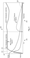
- the molten plastic material 114 first fills the mold cavity 122.
- the controller 140 increases the melt pressure to a substantially constant pressure value (e.g., approximately 10,000 psi) and then causes the melt pressure to hold at or close to this pressure value while the molten plastic material 114 fills the mold cavity 122.
- the molten plastic material 114 then enters a pack/hold stage 204 where the melt pressure is maintained to ensure that all gaps in the mold cavity 122 are back filled.
- the mold cavity 122 is filled from the end of the flow channel back towards the gate 120.
- the melt pressure is either raised or lowered based on the amount of cavity pressure measured. The degree of change is dependent on the amount of cavity pressure and a multiplier, as will be discussed below, which are determined during process validation and adjusted as needed.
- step time is equal to the time required to fill the mold cavity 122 (e.g., a "fill time") plus a process factor adjustment (“PFA") value.
- PFA is a multiplier to the amount of cavity pressure measured in the mold. As cavity pressure is measured, an adjustment to the melt pressure set point takes place based on a multiplier that is determined during the validation of the process (PFA). This multiplier can be adjusted as necessary to make a quality part.
- the overall step time corresponds to the duration of stage 202, and therefore is intended to remain a fixed value. However, in some examples, the actual step time for each injection cycle may vary depending on material characteristics.
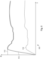
- a recovery profile 300 commences where the screw 112 returns to the first position 112a.
- an ideal recovery pattern in the form of an ideal back pressure set point 310 is identified and used as an input to control operation of the injection molding machine 100.
- the back pressure set point 310 is used as the input which determines how the machine 100 should operate, while the sensor 128 provides feedback to the controller 140 to determine whether adjustments should be made to match the back pressure set point 310.
Landscapes
- Engineering & Computer Science (AREA)
- Manufacturing & Machinery (AREA)
- Mechanical Engineering (AREA)
- Injection Moulding Of Plastics Or The Like (AREA)
Claims (15)
- Verfahren zum Steuern einer Spritzgießmaschine, die eine Gießform aufweist, die einen Gießformhohlraum ausbildet, wobei die Spritzgießmaschine gemäß einem Einspritzzyklus gesteuert wird, das Verfahren umfassend:Einspritzen eines geschmolzenen Polymers in den Gießformhohlraum gemäß dem Einspritzzyklus unter Verwendung einer Schnecke, die sich von einer ersten Position in eine zweite Position bewegt;nach Abschluss des Einspritzzyklus, Beginnen eines Rückstellungsprofils, bei dem die Schnecke in die erste Position bewegt wird;Messen, unter Verwendung eines Sensors, wenigstens einer Variablen während des Rückstellungsprofils; undEinstellen wenigstens eines Betriebsparameters der Spritzgießmaschine basierend auf der wenigstens einen gemessenen Variable während des Rückstellungsprofils,dadurch gekennzeichnet, dass die wenigstens eine Variable einen Düsendruck umfasst und der Betriebsparameter einen Gegendruck umfasst, wobei der Gegendruck gemäß dem erfassten Düsendruck eingestellt wird.
- Verfahren nach Anspruch 1, ferner umfassend ein Erstellen, durch einen oder mehrere Prozessoren, eines Rückstellungsprofils einer Zielvariablen für einen Einspritzzyklus der Spritzgießmaschine.
- Verfahren nach Anspruch 1 oder 2, wobei der wenigstens eine Betriebsparameter wenigstens eines von einem Gegendrucksollwert oder einer Schneckendrehgeschwindigkeit umfasst.
- Verfahren nach einem der Ansprüche 1 bis 3, wobei die wenigstens eine Variable einen Druckbetrag eines geschmolzenen Polymers umfasst, das in Richtung einer Düse der Schnecke gedrückt wird.
- Verfahren nach einem der Ansprüche 1 bis 4, wobei die wenigstens eine Variable einen Gegendruckbetrag umfasst.
- Verfahren nach einem der Ansprüche 1 bis 5, wobei der Sensor an einem Vorderende der Schnecke nahe der Düse angeordnet ist und/oder wobei der Sensor an einer Position vor einem Prüfring der Schnecke angeordnet ist.
- Verfahren nach einem der Ansprüche 1 bis 6, wobei die wenigstens eine Variable einen Düsendruck umfasst und wobei der Betriebsparameter einen einstellbaren Gegendruck, der eine Vielzahl von diskreten Sollwerten aufweist, umfasst, wobei der Gegendruck gemäß dem erfassten Düsendruck eingestellt wird.
- Spritzgießmaschine, umfassend:eine Einspritzeinheit, die eine Gießform, die einen Gießformhohlraum ausbildet, und eine Schnecke aufweist, die sich von einer ersten Position in eine zweite Position bewegt, wobei die Einspritzeinheit angepasst ist, um ein geschmolzenes Kunststoffmaterial aufzunehmen und über die Schnecke in den Gießformhohlraum einzuspritzen, um ein gegossenes Teil auszubilden;einen Regler, der angepasst ist, um einen Betrieb der Spritzgießmaschine gemäß einem Einspritzzyklus und einem Rückstellungsprofil zu regeln;einen Sensor, der mit der Spritzgießmaschine und dem Regler gekoppelt ist, wobei der Sensor angepasst ist, um während des Rückstellungsprofil wenigstens eine Variable zu messen;wobei der Regler nach Abschluss des Einspritzzyklus das Rückstellungsprofil beginnt, bei dem die Schnecke in die erste Position bewegt wird, wobei der Regler ferner einen Betriebsparameter der Spritzgießmaschine basierend auf der wenigstens einen gemessenen Variable einstellt,dadurch gekennzeichnet, dass die wenigstens eine Variable einen Düsendruck umfasst und der Betriebsparameter einen Gegendruck umfasst, wobei der Gegendruck gemäß dem erfassten Düsendruck eingestellt wird.
- Spritzgießmaschine nach Anspruch 8, wobei der Betriebsparameter wenigstens eines von einem Gegendrucksollwert oder einer Schneckendrehgeschwindigkeit umfasst.
- Spritzgießmaschine nach Anspruch 8 oder 9, wobei die wenigstens eine Variable einen Druckbetrag des geschmolzenen Polymers umfasst, das in Richtung einer Düse der Schnecke gedrückt wird.
- Spritzgießmaschine nach einem der Ansprüche 8 bis 10, wobei die wenigstens eine Variable einen Gegendruckbetrag umfasst.
- Spritzgießmaschine nach einem der Ansprüche 8 bis 11, wobei der Sensor an einem Vorderende der Schnecke nahe der Düse angeordnet ist und/oder wobei der Sensor an einer Position vor einem Prüfring der Schnecke angeordnet ist.
- Spritzgießmaschine nach einem der Ansprüche 8 bis 12, wobei die wenigstens eine Variable einen Düsendruck umfasst und wobei der Betriebsparameter einen ununterbrochen variablen Gegendruck umfasst, wobei der variable Gegendruck gemäß dem erfassten Düsendruck eingestellt wird.
- Nichtflüchtiges computerlesbares Speicherungsmedium, das prozessorausführbare Anweisungen speichert, die, wenn sie ausgeführt werden, die Spritzgießmaschine nach den Ansprüchen 8 bis 13 veranlassen zum:Einspritzen eines geschmolzenen Polymers in den Gießformhohlraum gemäß dem Einspritzzyklus unter Verwendung einer Schnecke, die sich von einer ersten Position in eine zweite Position bewegt;nach Abschluss des Einspritzzyklus, Beginnen eines Rückstellungsprofils, bei dem die Schnecke in die erste Position bewegt wird;Messen, unter Verwendung eines Sensors, wenigstens einer Variablen während des Rückstellungsprofils; undEinstellen wenigstens eines Betriebsparameters der Spritzgießmaschine basierend auf der wenigstens einen gemessenen Variablen während des Rückstellungsprofils;dadurch gekennzeichnet, dass die wenigstens eine Variable einen Düsendruck umfasst und der Betriebsparameter einen Gegendruck umfasst, wobei der Gegendruck gemäß dem erfassten Düsendruck eingestellt wird.
- Client-Vorrichtung, umfassend:einen oder mehrere Prozessoren;eine oder mehrere Schnittstellen;die Spritzgießmaschine nach den Ansprüchen 8 bis 13;einen nichtflüchtigen computerlesbaren Speicher, der darauf Anweisungen speichert, die, wenn sie durch den einen oder die mehreren Prozessoren ausgeführt werden, die Client-Vorrichtung veranlassen zum:Einspritzen eines geschmolzenen Polymers in den Gießformhohlraum gemäß dem Einspritzzyklus unter Verwendung einer Schnecke, die sich von einer ersten Position in eine zweite Position bewegt;nach Abschluss des Einspritzzyklus, Beginnen eines Rückstellungsprofils, bei dem die Schnecke in die erste Position bewegt wird;Messen, unter Verwendung eines Sensors, wenigstens einer Variablen während des Rückstellungsprofils; undEinstellen wenigstens eines Betriebsparameters der Spritzgießmaschine basierend auf der wenigstens einen gemessenen Variable während des Rückstellungsprofils,dadurch gekennzeichnet, dass die wenigstens eine Variable einen Düsendruck umfasst und der Betriebsparameter einen Gegendruck umfasst, wobei der Gegendruck gemäß dem erfassten Düsendruck eingestellt wird.
Applications Claiming Priority (2)
| Application Number | Priority Date | Filing Date | Title |
|---|---|---|---|
| US201862728272P | 2018-09-07 | 2018-09-07 | |
| PCT/US2019/049840 WO2020051391A1 (en) | 2018-09-07 | 2019-09-06 | Systems and approaches for controlling an injection molding machine |
Publications (2)
| Publication Number | Publication Date |
|---|---|
| EP3846997A1 EP3846997A1 (de) | 2021-07-14 |
| EP3846997B1 true EP3846997B1 (de) | 2025-07-09 |
Family
ID=67998752
Family Applications (1)
| Application Number | Title | Priority Date | Filing Date |
|---|---|---|---|
| EP19772942.9A Active EP3846997B1 (de) | 2018-09-07 | 2019-09-06 | Systeme und ansätze zur steuerung einer spritzgiessmaschine |
Country Status (7)
| Country | Link |
|---|---|
| US (1) | US20200078999A1 (de) |
| EP (1) | EP3846997B1 (de) |
| JP (1) | JP2021535852A (de) |
| CN (1) | CN112969564A (de) |
| CA (1) | CA3111342A1 (de) |
| MX (1) | MX2021002491A (de) |
| WO (1) | WO2020051391A1 (de) |
Families Citing this family (5)
| Publication number | Priority date | Publication date | Assignee | Title |
|---|---|---|---|---|
| JP7693542B2 (ja) | 2018-12-20 | 2025-06-17 | ベーアーエスエフ・エスエー | ポリアクリレートポリマー |
| JP7274348B2 (ja) * | 2019-05-21 | 2023-05-16 | 芝浦機械株式会社 | 溶融樹脂の流動性指標測定方法 |
| WO2021257116A1 (en) * | 2020-06-15 | 2021-12-23 | iMFLUX Inc. | Injection molding having variable volume recovery |
| AT525104A1 (de) * | 2021-05-18 | 2022-12-15 | Wittmann Tech Gmbh | Verfahren zur Verarbeitung von wiederverwendetem oder rezykliertem Schüttgut, insbesondere Feststoffen, wie Granulate, Pulver, Körner, Folien, Schnipsel, o. dgl., vorzugsweise für kunststoffverarbeitende Maschinen und Kunststoffverarbeitungsanlagen hierfür |
| JP7795503B2 (ja) * | 2023-08-07 | 2026-01-07 | 日精樹脂工業株式会社 | 粉砕材混合材料の成形支援方法及び装置 |
Citations (3)
| Publication number | Priority date | Publication date | Assignee | Title |
|---|---|---|---|---|
| EP1063073B1 (de) * | 1999-05-25 | 2010-12-22 | Fanuc Ltd | Dosierungsregelung für eine Spritzgiessmaschine |
| WO2012173224A1 (ja) * | 2011-06-16 | 2012-12-20 | 富士フイルム株式会社 | 射出成形方法 |
| DE102013009368A1 (de) * | 2012-06-11 | 2013-12-12 | Fanuc Corporation | Druckregelvorrichtung für eine Spritzgießmaschine |
Family Cites Families (10)
| Publication number | Priority date | Publication date | Assignee | Title |
|---|---|---|---|---|
| US3642402A (en) * | 1970-03-10 | 1972-02-15 | Pennwalt Corp | Injection molding process control |
| JPS60199623A (ja) * | 1984-03-26 | 1985-10-09 | Ube Ind Ltd | 射出成形機の可塑化制御方法 |
| JP3475725B2 (ja) * | 1997-06-20 | 2003-12-08 | 松下電工株式会社 | 射出成形方法およびその装置 |
| JP3649714B2 (ja) * | 2002-11-05 | 2005-05-18 | ファナック株式会社 | 射出成形機の制御装置 |
| JP3940101B2 (ja) * | 2003-07-18 | 2007-07-04 | 東洋機械金属株式会社 | 射出成形機の計量制御方法 |
| US7291297B2 (en) * | 2004-01-23 | 2007-11-06 | Husky Injection Molding Systems Ltd. | Injection molding method and apparatus for continuous plastication |
| US20090057938A1 (en) * | 2007-08-28 | 2009-03-05 | Husky Injection Molding Systems Ltd. | Closed Loop Control for an Injection Unit |
| CN101890792B (zh) * | 2009-05-22 | 2013-09-11 | 田贵熙 | 塑料注塑和挤出过程中的能量分配与消耗控制方法 |
| JP5698294B2 (ja) * | 2013-03-28 | 2015-04-08 | 株式会社日本製鋼所 | 成形サイクル開始のための準備工程における計量方法 |
| CN107787270B (zh) * | 2015-07-20 | 2020-08-25 | 克劳斯玛菲科技有限公司 | 用于运行注塑成型机的方法 |
-
2019
- 2019-09-06 CA CA3111342A patent/CA3111342A1/en active Pending
- 2019-09-06 MX MX2021002491A patent/MX2021002491A/es unknown
- 2019-09-06 WO PCT/US2019/049840 patent/WO2020051391A1/en not_active Ceased
- 2019-09-06 CN CN201980071899.7A patent/CN112969564A/zh not_active Withdrawn
- 2019-09-06 US US16/562,510 patent/US20200078999A1/en not_active Abandoned
- 2019-09-06 JP JP2021512793A patent/JP2021535852A/ja active Pending
- 2019-09-06 EP EP19772942.9A patent/EP3846997B1/de active Active
Patent Citations (4)
| Publication number | Priority date | Publication date | Assignee | Title |
|---|---|---|---|---|
| EP1063073B1 (de) * | 1999-05-25 | 2010-12-22 | Fanuc Ltd | Dosierungsregelung für eine Spritzgiessmaschine |
| WO2012173224A1 (ja) * | 2011-06-16 | 2012-12-20 | 富士フイルム株式会社 | 射出成形方法 |
| DE102013009368A1 (de) * | 2012-06-11 | 2013-12-12 | Fanuc Corporation | Druckregelvorrichtung für eine Spritzgießmaschine |
| JP2013256019A (ja) * | 2012-06-11 | 2013-12-26 | Fanuc Ltd | 射出成形機の圧力制御装置 |
Also Published As
| Publication number | Publication date |
|---|---|
| CA3111342A1 (en) | 2020-03-12 |
| MX2021002491A (es) | 2021-03-25 |
| CN112969564A (zh) | 2021-06-15 |
| WO2020051391A1 (en) | 2020-03-12 |
| JP2021535852A (ja) | 2021-12-23 |
| US20200078999A1 (en) | 2020-03-12 |
| EP3846997A1 (de) | 2021-07-14 |
Similar Documents
| Publication | Publication Date | Title |
|---|---|---|
| EP3846997B1 (de) | Systeme und ansätze zur steuerung einer spritzgiessmaschine | |
| US20230031650A1 (en) | Systems and Approaches for Controlling an Injection Molding Machine | |
| US20220168938A1 (en) | Closed Loop Control for Injection Molding Processes | |
| EP3849772B1 (de) | Verfahren zur steuerung von spritzgiessprozessen auf basis von tatsächlichem kunststoffschmelzdruck oder hohlraumdruck | |
| EP3642001B1 (de) | Spritzgiessen von vernetzten polymeren mit dehnungsdaten | |
| US20210206041A1 (en) | Melt Pressure Control of Injection Molding | |
| US20230041317A1 (en) | Systems and approaches for controlling an injection molding machine | |
| US20230234271A1 (en) | Methods for controlling co-injection plastic pressure ratio between individual flow front layers | |
| US20240308123A1 (en) | Systems and Approaches for Manufacturing Parts | |
| US20210387391A1 (en) | Independent startup mode for injection molding |
Legal Events
| Date | Code | Title | Description |
|---|---|---|---|
| STAA | Information on the status of an ep patent application or granted ep patent |
Free format text: STATUS: UNKNOWN |
|
| STAA | Information on the status of an ep patent application or granted ep patent |
Free format text: STATUS: THE INTERNATIONAL PUBLICATION HAS BEEN MADE |
|
| PUAI | Public reference made under article 153(3) epc to a published international application that has entered the european phase |
Free format text: ORIGINAL CODE: 0009012 |
|
| STAA | Information on the status of an ep patent application or granted ep patent |
Free format text: STATUS: REQUEST FOR EXAMINATION WAS MADE |
|
| 17P | Request for examination filed |
Effective date: 20210305 |
|
| AK | Designated contracting states |
Kind code of ref document: A1 Designated state(s): AL AT BE BG CH CY CZ DE DK EE ES FI FR GB GR HR HU IE IS IT LI LT LU LV MC MK MT NL NO PL PT RO RS SE SI SK SM TR |
|
| DAV | Request for validation of the european patent (deleted) | ||
| DAX | Request for extension of the european patent (deleted) | ||
| STAA | Information on the status of an ep patent application or granted ep patent |
Free format text: STATUS: EXAMINATION IS IN PROGRESS |
|
| 17Q | First examination report despatched |
Effective date: 20230913 |
|
| GRAP | Despatch of communication of intention to grant a patent |
Free format text: ORIGINAL CODE: EPIDOSNIGR1 |
|
| STAA | Information on the status of an ep patent application or granted ep patent |
Free format text: STATUS: GRANT OF PATENT IS INTENDED |
|
| INTG | Intention to grant announced |
Effective date: 20250206 |
|
| GRAS | Grant fee paid |
Free format text: ORIGINAL CODE: EPIDOSNIGR3 |
|
| GRAA | (expected) grant |
Free format text: ORIGINAL CODE: 0009210 |
|
| STAA | Information on the status of an ep patent application or granted ep patent |
Free format text: STATUS: THE PATENT HAS BEEN GRANTED |
|
| RAP1 | Party data changed (applicant data changed or rights of an application transferred) |
Owner name: THE PROCTER & GAMBLE COMPANY |
|
| AK | Designated contracting states |
Kind code of ref document: B1 Designated state(s): AL AT BE BG CH CY CZ DE DK EE ES FI FR GB GR HR HU IE IS IT LI LT LU LV MC MK MT NL NO PL PT RO RS SE SI SK SM TR |
|
| P01 | Opt-out of the competence of the unified patent court (upc) registered |
Free format text: CASE NUMBER: APP_26212/2025 Effective date: 20250603 |
|
| REG | Reference to a national code |
Ref country code: GB Ref legal event code: FG4D |
|
| REG | Reference to a national code |
Ref country code: CH Ref legal event code: EP |
|
| REG | Reference to a national code |
Ref country code: IE Ref legal event code: FG4D |
|
| REG | Reference to a national code |
Ref country code: DE Ref legal event code: R096 Ref document number: 602019072316 Country of ref document: DE |
|
| PGFP | Annual fee paid to national office [announced via postgrant information from national office to epo] |
Ref country code: DE Payment date: 20250730 Year of fee payment: 7 |
|
| REG | Reference to a national code |
Ref country code: NL Ref legal event code: MP Effective date: 20250709 |
|
| PG25 | Lapsed in a contracting state [announced via postgrant information from national office to epo] |
Ref country code: PT Free format text: LAPSE BECAUSE OF FAILURE TO SUBMIT A TRANSLATION OF THE DESCRIPTION OR TO PAY THE FEE WITHIN THE PRESCRIBED TIME-LIMIT Effective date: 20251110 |
|
| PG25 | Lapsed in a contracting state [announced via postgrant information from national office to epo] |
Ref country code: NL Free format text: LAPSE BECAUSE OF FAILURE TO SUBMIT A TRANSLATION OF THE DESCRIPTION OR TO PAY THE FEE WITHIN THE PRESCRIBED TIME-LIMIT Effective date: 20250709 |
|
| REG | Reference to a national code |
Ref country code: AT Ref legal event code: MK05 Ref document number: 1811464 Country of ref document: AT Kind code of ref document: T Effective date: 20250709 |
|
| PG25 | Lapsed in a contracting state [announced via postgrant information from national office to epo] |
Ref country code: IS Free format text: LAPSE BECAUSE OF FAILURE TO SUBMIT A TRANSLATION OF THE DESCRIPTION OR TO PAY THE FEE WITHIN THE PRESCRIBED TIME-LIMIT Effective date: 20251109 |
|
| PG25 | Lapsed in a contracting state [announced via postgrant information from national office to epo] |
Ref country code: NO Free format text: LAPSE BECAUSE OF FAILURE TO SUBMIT A TRANSLATION OF THE DESCRIPTION OR TO PAY THE FEE WITHIN THE PRESCRIBED TIME-LIMIT Effective date: 20251009 |
|
| REG | Reference to a national code |
Ref country code: LT Ref legal event code: MG9D |
|
| PG25 | Lapsed in a contracting state [announced via postgrant information from national office to epo] |
Ref country code: AT Free format text: LAPSE BECAUSE OF FAILURE TO SUBMIT A TRANSLATION OF THE DESCRIPTION OR TO PAY THE FEE WITHIN THE PRESCRIBED TIME-LIMIT Effective date: 20250709 |
|
| PG25 | Lapsed in a contracting state [announced via postgrant information from national office to epo] |
Ref country code: FI Free format text: LAPSE BECAUSE OF FAILURE TO SUBMIT A TRANSLATION OF THE DESCRIPTION OR TO PAY THE FEE WITHIN THE PRESCRIBED TIME-LIMIT Effective date: 20250709 |
|
| PG25 | Lapsed in a contracting state [announced via postgrant information from national office to epo] |
Ref country code: HR Free format text: LAPSE BECAUSE OF FAILURE TO SUBMIT A TRANSLATION OF THE DESCRIPTION OR TO PAY THE FEE WITHIN THE PRESCRIBED TIME-LIMIT Effective date: 20250709 |
|
| PG25 | Lapsed in a contracting state [announced via postgrant information from national office to epo] |
Ref country code: GR Free format text: LAPSE BECAUSE OF FAILURE TO SUBMIT A TRANSLATION OF THE DESCRIPTION OR TO PAY THE FEE WITHIN THE PRESCRIBED TIME-LIMIT Effective date: 20251010 |
|
| PG25 | Lapsed in a contracting state [announced via postgrant information from national office to epo] |
Ref country code: SE Free format text: LAPSE BECAUSE OF FAILURE TO SUBMIT A TRANSLATION OF THE DESCRIPTION OR TO PAY THE FEE WITHIN THE PRESCRIBED TIME-LIMIT Effective date: 20250709 |
|
| PG25 | Lapsed in a contracting state [announced via postgrant information from national office to epo] |
Ref country code: LV Free format text: LAPSE BECAUSE OF FAILURE TO SUBMIT A TRANSLATION OF THE DESCRIPTION OR TO PAY THE FEE WITHIN THE PRESCRIBED TIME-LIMIT Effective date: 20250709 |
|
| PG25 | Lapsed in a contracting state [announced via postgrant information from national office to epo] |
Ref country code: PL Free format text: LAPSE BECAUSE OF FAILURE TO SUBMIT A TRANSLATION OF THE DESCRIPTION OR TO PAY THE FEE WITHIN THE PRESCRIBED TIME-LIMIT Effective date: 20250709 Ref country code: BG Free format text: LAPSE BECAUSE OF FAILURE TO SUBMIT A TRANSLATION OF THE DESCRIPTION OR TO PAY THE FEE WITHIN THE PRESCRIBED TIME-LIMIT Effective date: 20250709 |
|
| PG25 | Lapsed in a contracting state [announced via postgrant information from national office to epo] |
Ref country code: RS Free format text: LAPSE BECAUSE OF FAILURE TO SUBMIT A TRANSLATION OF THE DESCRIPTION OR TO PAY THE FEE WITHIN THE PRESCRIBED TIME-LIMIT Effective date: 20251009 |
|
| PG25 | Lapsed in a contracting state [announced via postgrant information from national office to epo] |
Ref country code: ES Free format text: LAPSE BECAUSE OF FAILURE TO SUBMIT A TRANSLATION OF THE DESCRIPTION OR TO PAY THE FEE WITHIN THE PRESCRIBED TIME-LIMIT Effective date: 20250709 |
|
| PG25 | Lapsed in a contracting state [announced via postgrant information from national office to epo] |
Ref country code: RO Free format text: LAPSE BECAUSE OF FAILURE TO SUBMIT A TRANSLATION OF THE DESCRIPTION OR TO PAY THE FEE WITHIN THE PRESCRIBED TIME-LIMIT Effective date: 20250709 |
|
| PG25 | Lapsed in a contracting state [announced via postgrant information from national office to epo] |
Ref country code: SM Free format text: LAPSE BECAUSE OF FAILURE TO SUBMIT A TRANSLATION OF THE DESCRIPTION OR TO PAY THE FEE WITHIN THE PRESCRIBED TIME-LIMIT Effective date: 20250709 |
|
| PG25 | Lapsed in a contracting state [announced via postgrant information from national office to epo] |
Ref country code: DK Free format text: LAPSE BECAUSE OF FAILURE TO SUBMIT A TRANSLATION OF THE DESCRIPTION OR TO PAY THE FEE WITHIN THE PRESCRIBED TIME-LIMIT Effective date: 20250709 |
|
| PG25 | Lapsed in a contracting state [announced via postgrant information from national office to epo] |
Ref country code: IT Free format text: LAPSE BECAUSE OF FAILURE TO SUBMIT A TRANSLATION OF THE DESCRIPTION OR TO PAY THE FEE WITHIN THE PRESCRIBED TIME-LIMIT Effective date: 20250709 |