EP3847002B1 - Procédé d'impression pour l'impression fdm de surfaces lisses d'articles - Google Patents
Procédé d'impression pour l'impression fdm de surfaces lisses d'articles Download PDFInfo
- Publication number
- EP3847002B1 EP3847002B1 EP19759001.1A EP19759001A EP3847002B1 EP 3847002 B1 EP3847002 B1 EP 3847002B1 EP 19759001 A EP19759001 A EP 19759001A EP 3847002 B1 EP3847002 B1 EP 3847002B1
- Authority
- EP
- European Patent Office
- Prior art keywords
- shell
- core
- layer
- item
- nozzle
- Prior art date
- Legal status (The legal status is an assumption and is not a legal conclusion. Google has not performed a legal analysis and makes no representation as to the accuracy of the status listed.)
- Active
Links
Images


Classifications
-
- B—PERFORMING OPERATIONS; TRANSPORTING
- B29—WORKING OF PLASTICS; WORKING OF SUBSTANCES IN A PLASTIC STATE IN GENERAL
- B29C—SHAPING OR JOINING OF PLASTICS; SHAPING OF MATERIAL IN A PLASTIC STATE, NOT OTHERWISE PROVIDED FOR; AFTER-TREATMENT OF THE SHAPED PRODUCTS, e.g. REPAIRING
- B29C64/00—Additive manufacturing, i.e. manufacturing of three-dimensional [3D] objects by additive deposition, additive agglomeration or additive layering, e.g. by 3D printing, stereolithography or selective laser sintering
- B29C64/10—Processes of additive manufacturing
- B29C64/106—Processes of additive manufacturing using only liquids or viscous materials, e.g. depositing a continuous bead of viscous material
- B29C64/118—Processes of additive manufacturing using only liquids or viscous materials, e.g. depositing a continuous bead of viscous material using filamentary material being melted, e.g. fused deposition modelling [FDM]
-
- B—PERFORMING OPERATIONS; TRANSPORTING
- B29—WORKING OF PLASTICS; WORKING OF SUBSTANCES IN A PLASTIC STATE IN GENERAL
- B29C—SHAPING OR JOINING OF PLASTICS; SHAPING OF MATERIAL IN A PLASTIC STATE, NOT OTHERWISE PROVIDED FOR; AFTER-TREATMENT OF THE SHAPED PRODUCTS, e.g. REPAIRING
- B29C64/00—Additive manufacturing, i.e. manufacturing of three-dimensional [3D] objects by additive deposition, additive agglomeration or additive layering, e.g. by 3D printing, stereolithography or selective laser sintering
- B29C64/20—Apparatus for additive manufacturing; Details thereof or accessories therefor
- B29C64/205—Means for applying layers
- B29C64/209—Heads; Nozzles
-
- B—PERFORMING OPERATIONS; TRANSPORTING
- B29—WORKING OF PLASTICS; WORKING OF SUBSTANCES IN A PLASTIC STATE IN GENERAL
- B29C—SHAPING OR JOINING OF PLASTICS; SHAPING OF MATERIAL IN A PLASTIC STATE, NOT OTHERWISE PROVIDED FOR; AFTER-TREATMENT OF THE SHAPED PRODUCTS, e.g. REPAIRING
- B29C64/00—Additive manufacturing, i.e. manufacturing of three-dimensional [3D] objects by additive deposition, additive agglomeration or additive layering, e.g. by 3D printing, stereolithography or selective laser sintering
- B29C64/20—Apparatus for additive manufacturing; Details thereof or accessories therefor
- B29C64/245—Platforms or substrates
-
- B—PERFORMING OPERATIONS; TRANSPORTING
- B29—WORKING OF PLASTICS; WORKING OF SUBSTANCES IN A PLASTIC STATE IN GENERAL
- B29C—SHAPING OR JOINING OF PLASTICS; SHAPING OF MATERIAL IN A PLASTIC STATE, NOT OTHERWISE PROVIDED FOR; AFTER-TREATMENT OF THE SHAPED PRODUCTS, e.g. REPAIRING
- B29C64/00—Additive manufacturing, i.e. manufacturing of three-dimensional [3D] objects by additive deposition, additive agglomeration or additive layering, e.g. by 3D printing, stereolithography or selective laser sintering
- B29C64/30—Auxiliary operations or equipment
- B29C64/307—Handling of material to be used in additive manufacturing
- B29C64/321—Feeding
- B29C64/336—Feeding of two or more materials
-
- B—PERFORMING OPERATIONS; TRANSPORTING
- B29—WORKING OF PLASTICS; WORKING OF SUBSTANCES IN A PLASTIC STATE IN GENERAL
- B29C—SHAPING OR JOINING OF PLASTICS; SHAPING OF MATERIAL IN A PLASTIC STATE, NOT OTHERWISE PROVIDED FOR; AFTER-TREATMENT OF THE SHAPED PRODUCTS, e.g. REPAIRING
- B29C71/00—After-treatment of articles without altering their shape; Apparatus therefor
- B29C71/0009—After-treatment of articles without altering their shape; Apparatus therefor using liquids, e.g. solvents, swelling agents
-
- B—PERFORMING OPERATIONS; TRANSPORTING
- B33—ADDITIVE MANUFACTURING TECHNOLOGY
- B33Y—ADDITIVE MANUFACTURING, i.e. MANUFACTURING OF THREE-DIMENSIONAL [3D] OBJECTS BY ADDITIVE DEPOSITION, ADDITIVE AGGLOMERATION OR ADDITIVE LAYERING, e.g. BY 3D PRINTING, STEREOLITHOGRAPHY OR SELECTIVE LASER SINTERING
- B33Y10/00—Processes of additive manufacturing
-
- B—PERFORMING OPERATIONS; TRANSPORTING
- B33—ADDITIVE MANUFACTURING TECHNOLOGY
- B33Y—ADDITIVE MANUFACTURING, i.e. MANUFACTURING OF THREE-DIMENSIONAL [3D] OBJECTS BY ADDITIVE DEPOSITION, ADDITIVE AGGLOMERATION OR ADDITIVE LAYERING, e.g. BY 3D PRINTING, STEREOLITHOGRAPHY OR SELECTIVE LASER SINTERING
- B33Y40/00—Auxiliary operations or equipment, e.g. for material handling
-
- B—PERFORMING OPERATIONS; TRANSPORTING
- B33—ADDITIVE MANUFACTURING TECHNOLOGY
- B33Y—ADDITIVE MANUFACTURING, i.e. MANUFACTURING OF THREE-DIMENSIONAL [3D] OBJECTS BY ADDITIVE DEPOSITION, ADDITIVE AGGLOMERATION OR ADDITIVE LAYERING, e.g. BY 3D PRINTING, STEREOLITHOGRAPHY OR SELECTIVE LASER SINTERING
- B33Y70/00—Materials specially adapted for additive manufacturing
-
- B—PERFORMING OPERATIONS; TRANSPORTING
- B29—WORKING OF PLASTICS; WORKING OF SUBSTANCES IN A PLASTIC STATE IN GENERAL
- B29K—INDEXING SCHEME ASSOCIATED WITH SUBCLASSES B29B, B29C OR B29D, RELATING TO MOULDING MATERIALS OR TO MATERIALS FOR MOULDS, REINFORCEMENTS, FILLERS OR PREFORMED PARTS, e.g. INSERTS
- B29K2101/00—Use of unspecified macromolecular compounds as moulding material
- B29K2101/12—Thermoplastic materials
-
- B—PERFORMING OPERATIONS; TRANSPORTING
- B29—WORKING OF PLASTICS; WORKING OF SUBSTANCES IN A PLASTIC STATE IN GENERAL
- B29K—INDEXING SCHEME ASSOCIATED WITH SUBCLASSES B29B, B29C OR B29D, RELATING TO MOULDING MATERIALS OR TO MATERIALS FOR MOULDS, REINFORCEMENTS, FILLERS OR PREFORMED PARTS, e.g. INSERTS
- B29K2995/00—Properties of moulding materials, reinforcements, fillers, preformed parts or moulds
- B29K2995/0037—Other properties
- B29K2995/0072—Roughness, e.g. anti-slip
- B29K2995/0073—Roughness, e.g. anti-slip smooth
-
- B—PERFORMING OPERATIONS; TRANSPORTING
- B33—ADDITIVE MANUFACTURING TECHNOLOGY
- B33Y—ADDITIVE MANUFACTURING, i.e. MANUFACTURING OF THREE-DIMENSIONAL [3D] OBJECTS BY ADDITIVE DEPOSITION, ADDITIVE AGGLOMERATION OR ADDITIVE LAYERING, e.g. BY 3D PRINTING, STEREOLITHOGRAPHY OR SELECTIVE LASER SINTERING
- B33Y80/00—Products made by additive manufacturing
-
- D—TEXTILES; PAPER
- D01—NATURAL OR MAN-MADE THREADS OR FIBRES; SPINNING
- D01F—CHEMICAL FEATURES IN THE MANUFACTURE OF ARTIFICIAL FILAMENTS, THREADS, FIBRES, BRISTLES OR RIBBONS; APPARATUS SPECIALLY ADAPTED FOR THE MANUFACTURE OF CARBON FILAMENTS
- D01F8/00—Conjugated, i.e. bi- or multicomponent, artificial filaments or the like; Manufacture thereof
- D01F8/04—Conjugated, i.e. bi- or multicomponent, artificial filaments or the like; Manufacture thereof from synthetic polymers
Definitions
- the invention relates to a method for manufacturing a 3D (printed) item and to a software product for executing such method.
- the invention also relates to the 3D (printed) item obtainable with such method. Further, the invention relates to a lighting device including such 3D (printed) item.
- extruded 3D printer inputs containing layers is known in the art.
- WO2015/077262 describes 3D printer inputs including filaments comprising separated layers or sections. These inputs particularly including filaments may be prepared by coextrusion, microlayer coextrusion or multicomponent/fractal coextrusion. These inputs and specifically filaments enable layering or combining different materials simultaneously through one or more nozzles during the so-called 3D printing process. These techniques facilitate smaller layer sizes (milli, micro, and nano) different layer configurations as well as the potential to incorporate materials that would otherwise not be usable in standard 3D printer methods.
- WO2018/106705 discloses a 3D printed core-shell filament having an elongated core that is radially surrounded by an outer shell with a barrier layer in between.
- the elongated core comprises a ductile polymer and the outer shell comprises a stiff polymer having a Young's modulus higher than that of the ductile polymer.
- 3D printing One of the aspects of digital fabrication is 3D printing.
- 3D printing can also be used in producing molds which can then be used for replicating objects.
- FDM Fused Deposition Modeling
- FDM Fused deposition modeling
- FDM is an additive manufacturing technology commonly used for modeling, prototyping, and production applications. FDM works on an "additive" principle by laying down material in layers; a plastic filament or metal wire is unwound from a coil and supplies material to produce a part. Possibly, (for thermoplastics for example) the filament is melted and extruded before being laid down. FDM is a rapid prototyping technology. Other terms for FDM are "fused filament fabrication” (FFF) or “filament 3D printing” (FDP), which are considered to be equivalent to FDM.
- FFF fused filament fabrication
- FDP filament 3D printing
- FDM printers use a thermoplastic filament, which is heated to its melting point and then extruded, layer by layer, (or in fact filament after filament) to create a three-dimensional object. FDM printers are relatively fast and can be used for printing complicated object.
- FDM printers are relatively fast, low cost and can be used for printing complicated 3D objects. Such printers are used in printing various shapes using various polymers. The technique is also being further developed in the production of LED luminaires and lighting solutions.
- FDM Fused Deposition Modelling
- a heat treatment of the entire 3D printed product may lead to weakening of the product, and thus loss of shape and/or functionality.
- Solvent or solvent vapor treatment may also be used for obtaining smooth surfaces.
- the object may e.g. be dipped in a solvent or gets subjected to a solvent vapor.
- solvent molecules penetrate the polymer ("3D printed material") and partially dissolve it. When a thin layer is used it leads to crack formation and or delamination and deformation of the object.
- the present invention may have as object to overcome or ameliorate at least one of the disadvantages of the prior art, or to provide a useful alternative.
- a filament having essentially concentric layers or using a printer nozzle and filament feeders so that two kinds of materials come out of the nozzle and form core-shell layers stacked next to each other or on top of each other.
- Materials can be chosen so that the outer surface is made of a polymer with which is soluble in the solvent which is to be used in the solvent treatment, whereas the core material does not get swollen or dissolved in this polymer.
- the object printed in this way may have a layer which has an outer surface which can at least partly be dissolved by the solvent while the inner material is not affected by the solvent. Placing the object in a solvent or subjecting it to the solvent vapor makes the outer polymer flow leading to a smooth surface structure while the inner polymer may essentially preserve the mechanical integrity and avoids the structure from cracking and collapsing.
- the invention provides a method for producing a 3D item by means of fused deposition modelling, the method comprising a 3D printing stage and an exposure stage (especially of the 3D printed item obtained in the 3D printing stage).
- the 3D printing stage comprises layer-wise depositing an extrudate comprising 3D printable material, wherein during at least part of the 3D printing stage the extrudate comprises a core-shell extrudate comprising (i) a core comprising a core material, and (ii) a shell (or "jacket"), comprising a shell material.
- the 3D item may be provided, comprising 3D printed material, wherein the 3D item especially comprises a plurality of layers of 3D printed material, wherein one or more of layers comprises one or more core-shell layer parts, wherein each of the core-shell layer parts comprises a layer core comprising the core material, and a layer shell comprising the shell material, wherein the 3D item has an item surface defined by at least part of the 3D printed material.
- the exposure stage may especially comprise exposing at least part of the item surface to a liquid, wherein the shell material may dissolve.
- the core material has core material solubility SC1 for the liquid and the shell material has a shell material solubility SS1 for the liquid, wherein SC1 ⁇ SS2.
- the core material comprises one or more of polycarbonate (PC), polyethylene
- the shell material comprises one or more of acrylonitrile butadiene styrene (ABS), poly(methyl methacrylate) (PMMA), polystyrene (PS), and styrene acrylic copolymers (SMMA).
- ABS acrylonitrile butadiene styrene
- PMMA poly(methyl methacrylate)
- PS polystyrene
- SMMA styrene acrylic copolymers
- the invention especially provides a method for producing a 3D item by means of fused deposition modelling, the method comprising:
- a 3D printed item may be provided wherein at least part of the item surface may be much smoother than would the surface not have been exposed to the liquid. Further, crack formation and/or delamination may be improved.
- the item surface may have the characteristic ribbed structure such as provided with FDM printed 3D items. However, due to the exposure, the part of the item surface that is exposed to the liquid obtains a smoother surface, with less roughness. Especially part of the shell material may be dissolved by which a smoothening effect of at least part of the item surface may be created. Further, with the present invention the mechanical properties which may especially be provided with the core material may be less effected, or not effected at all, as the core material may not essentially dissolve in the liquid.
- the aspect of dissolving may also have a time component.
- the shell material and core material may be chosen such that within a predetermined time period the part of the item surface that is exposed to the liquid becomes smoother and may reach a desired smoothness, while during that time period the core material is essentially not dissolved.
- surface roughness may be diminished from e.g. ⁇ m dimensions of the filaments to nm dimensions after heating.
- relatively easily smoothening may be executed. If desired, the entire item can be exposed to the liquid essentially without loss of shape and/or functionality.
- the backbone material which may essentially consist of the core material in each filament may stay essentially unaltered, while the surface is smoothened. Hence, a strong device with a relative smooth surface may be provided.
- the method is especially used for producing a 3D item by means of fused deposition modelling (FDM).
- FDM fused deposition modelling
- the method comprises two stages, a 3D printing stage and an exposure stage, wherein the latter is in general later than the former, though there maybe some overlap in time in other embodiments (see also below).
- the method may also comprise one or more further stages, like a heating stage for also smoothening the surface.
- there may be a finishing stage comprising an exposure stage to liquid and optionally a heating stage.
- finishing stage also the term "post processing" or similar terms may be applied.
- Other stages may also be available.
- stage may also refer to a sequence of stages, such as e.g. a sequence of printing stages wherein in between one or more functional components or other components are integrated in or arranged on the thus obtained 3D printed material.
- the 3D printing stage comprises layer-wise depositing an extrudate comprising 3D printable material, wherein during at least part of the 3D printing stage the extrudate comprises a core-shell extrudate comprising a core comprising a core material, and a shell comprising a shell material, to provide the 3D item comprising 3D printed material.
- the 3D printing process especially provides the 3D item which comprises a plurality of layers of 3D printed material, which are especially formed due to the layer-wise deposition.
- the extrudate comprises a core-shell extrudate.
- 3D printing may be executed wherein no core-shell extrudate is provided, but an extrudate of a single material, without essential composition differences throughout the cross-section of the extrude (i.e. "normal" 3D printing with a single nozzle).
- a way to accomplish this may be to stop feeding material to a core part or to a shell part of the printer head, by which from the nozzle as extrudate only a single material may escape and be deposited (see further also below).
- the core-shell extrudate may in some embodiments be obtained by using a core-shell filament that is fed to the printer head and leave (at least partially molten) the nozzle of the printer head.
- the core shell extrudate is obtained by using a core-shell nozzle, i.e. a nozzle that includes two opening, which, when 3D printable material is forced through the nozzle, provides the core-shell extrudate.
- core-shell may in specific embodiments also indicate a core-shell with a plurality of different shells.
- core-shell extrudate or core-shell layer parts consisting of a core and a (single) shell.
- the core may consist of a core and one or more shells, which together form the core. This core is at least partially surrounded with the shell.
- shell especially refers to the outer layer or set of outer layers (for instance in embodiments when the shell may comprise a plurality of shells).
- a (printer head with a) core-shell nozzle may be applied, as known in the art (see also above).
- the extrudate comprises a core-shell extrudate.
- the core-shell extrudate comprises a core comprising a core material, and a shell comprising a shell material.
- One or more of layers comprises one or more core-shell layer parts, wherein each of the core-shell layer parts comprises a layer core comprising the core material, and a layer shell comprising the shell material.
- each of the core-shell layer parts comprises a layer core comprising the core material, and a layer shell comprising the shell material.
- the entire layer can be indicated as core-shell layer part or as core-shell layer.
- part of the layer will not be of the core-shell type, leading to a layer comprising a core-shell layer part (or parts) (and a non-core-shell part or parts).
- core-shell layer part is used. This reflects the fact that in embodiments all layers may be core-shell layers, in embodiments part of the total number of layers may be core-shell layers, and in embodiments a part of a layer (or parts of layers) may be of the core-shell type. Hence, in embodiments not all layers maybe of the core-shell type, and in other embodiments all layers may be of the core-shell type.
- the core-shell layer part may have a length of less than 1 mm to a few mm, or much longer.
- the thickness and height may essentially be the same as a possible adjacent non-core-shell layer (part), as (in embodiments) the same nozzle may be used to provide core-shell layer (parts) and non-core shell layer parts.
- the thus obtained 3D item has an item surface defined by at least part of the 3D printed material. Especially, this item surface is (thus) defined by the shell material.
- the method comprises depositing during a printing stage 3D printable material.
- 3D printable material refers to the material to be deposited or printed
- 3D printed material refers to the material that is obtained after deposition. These materials may be essentially the same, as the 3D printable material may especially refer to the material in a printer head or extruder at elevated temperature and the 3D printed material refers to the same material, but in a later stage when deposited.
- the 3D printable material is printed as a filament and deposited as such.
- the 3D printable material may be provided as filament or may be formed into a filament. Hence, whatever starting materials are applied, a filament comprising 3D printable material is provided by the printer head and 3D printed.
- extrudate may be used to define the 3D printable material downstream of the printer head, but not yet deposited. The latter is indicated as “3D printed material”. In fact, the extrudate comprises 3D printable material, as the material is not yet deposited. Upon deposition of the 3D printable material or extrudate, the material is thus indicated as 3D printed material. Essentially, the materials are the same material, as the thermoplastic material upstream of the printer head, downstream of the printer head, and when deposited, is essentially the same material.
- 3D printable material may also be indicated as "printable material.
- polymeric material may in embodiments refer to a blend of different polymers, but may in embodiments also refer to essentially a single polymer type with different polymer chain lengths.
- polymeric material or polymer may refer to a single type of polymers but may also refer to a plurality of different polymers.
- printable material may refer to a single type of printable material but may also refer to a plurality of different printable materials.
- printed material may refer to a single type of printed material but may also refer to a plurality of different printed materials.
- the term "3D printable material” may also refer to a combination of two or more materials.
- these (polymeric) materials have a glass transition temperature T g and/or a melting temperature T m .
- the 3D printable material will be heated by the 3D printer before it leaves the nozzle to a temperature of at least the glass transition temperature, and in general at least the melting temperature.
- the 3D printable material comprises a thermoplastic polymer having a glass transition temperature (T g ) and /or a melting point (T m ), and the printer head action comprises heating the 3D printable material above the glass transition and if it is a semi-crystalline polymer above the melting temperature.
- the 3D printable material comprises a (thermoplastic) polymer having a melting point (T m ), and the printer head action comprises heating the 3D printable material to be deposited on the receiver item to a temperature of at least the melting point.
- T m melting point
- the glass transition temperature is in general not the same thing as the melting temperature. Melting is a transition which occurs in crystalline polymers. Melting happens when the polymer chains fall out of their crystal structures, and become a disordered liquid. The glass transition is a transition which happens to amorphous polymers; that is, polymers whose chains are not arranged in ordered crystals, but are just strewn around in any fashion, even though they are in the solid state.
- Polymers can be amorphous, essentially having a glass transition temperature and not a melting temperature or can be (semi) crystalline, in general having both a glass transition temperature and a melting temperature, with in general the latter being larger than the former.
- the glass temperature may e.g. be determined with differential scanning calorimetry.
- the melting point or melting temperature can also be determined with differential scanning calorimetry.
- the invention thus provides a method comprising providing a filament of 3D printable material and printing during a printing stage said 3D printable material on a substrate, to provide said 3D item.
- thermoplastic material optionally including additives, to a volume percentage of at maximum about 60%, especially at maximum about 30 vol.%, such as at maximum 20 vol.% (of the additives relative to the total volume of the thermoplastic material and additives).
- the printable material may thus in embodiments comprise two phases.
- the printable material may comprise a phase of printable polymeric material, especially thermoplastic material (see also below), which phase is especially an essentially continuous phase.
- thermoplastic material polymer additives such as one or more of antioxidant, heat stabilizer, light stabilizer, ultraviolet light stabilizer, ultraviolet light absorbing additive, near infrared light absorbing additive, infrared light absorbing additive, plasticizer, lubricant, release agent, antistatic agent, anti-fog agent, antimicrobial agent, colorant, laser marking additive, surface effect additive, radiation stabilizer, flame retardant, anti-drip agent may be present.
- the additive may have useful properties selected from optical properties, mechanical properties, electrical properties, thermal properties, and mechanical properties (see also above).
- the printable material in embodiments may comprise particulate material, i.e. particles embedded in the printable polymeric material, which particles form a substantially discontinuous phase.
- the number of particles in the total mixture is especially not larger than 60 vol.%, relative to the total volume of the printable material (including the (anisotropically conductive) particles) especially in applications for reducing thermal expansion coefficient.
- For optical and surface related effect number of particles in the total mixture is equal to or less than 20 vol.%, such as up to 10 vol.%, relative to the total volume of the printable material (including the particles).
- the 3D printable material especially refers to a continuous phase of essentially thermoplastic material, wherein other materials, such as particles, may be embedded.
- the 3D printed material especially refers to a continuous phase of essentially thermoplastic material, wherein other materials, such as particles, are embedded.
- the particles may comprise one or more additives as defined above.
- the 3D printable materials may comprises particulate additives.
- the 3D printable material of the shell differs from the 3D printable material of the core.
- the core material has a different composition than the shell material.
- the core material and the shell material comprise thermoplastic polymers, respectively.
- the compositions of the thermoplastic polymers differ. This may be useful for forming good core-shell extrudates (or filaments) and this may allow the shell to dissolve relatively fast, whereas the core is essentially not dissolved.
- the polymers are incompatible. Polymers which are incompatible cannot be mixed on a molecular level. When mixed together they become phase separated.
- the core material may comprise a first polymer and the shell material may comprise a second polymer, wherein the first polymer and the second polymer are not compatible. Therefore, in specific embodiments the core material and the shell material comprise different thermoplastic materials.
- the core material may comprise a first thermoplastic material and the shell material may comprise a second thermoplastic material that differs from the first thermoplastic material.
- solubilities of the core material and shell material
- the core material has core material solubility SC1 for the liquid and wherein the shell material has a shell material solubility SS1 for the liquid, wherein SC1 ⁇ SS2, especially SC1/SS2 ⁇ 0.5 (such as at room temperature (in general to be considered 20 °C)), like in embodiments in the range of 0.1-0.8.
- the core material comprises one or more of polycarbonate (PC), polyethylene (PE), high-density polyethylene (HDPE), polypropylene (PP), polyoxymethylene (POM), polyethylene naphthalate (PEN), styrene-acrylonitrile resin (SAN), polysulfone (PSU), polyphenylene sulfide (PPS), and (semi-crystalline) polytethylene terephthalate (PET).
- PC polycarbonate
- PE polyethylene
- HDPE high-density polyethylene
- PP polypropylene
- POM polyoxymethylene
- PEN polyethylene naphthalate
- SAN styrene-acrylonitrile resin
- PSU polysulfone
- PPS polyphenylene sulfide
- PET polytethylene terephthalate
- the core material may comprise one or more different thermoplastic materials.
- other materials may be available, like particulate material embedded in the core material.
- the shell material comprises one or more of acrylonitrile butadiene styrene (ABS), poly(methyl methacrylate) (PMMA), polystyrene (PS), and styrene acrylic copolymers (SMMA).
- ABS acrylonitrile butadiene styrene
- PMMA poly(methyl methacrylate)
- PS polystyrene
- SMMA styrene acrylic copolymers
- the shell material may comprise one or more different thermoplastic materials.
- other materials may be available, like particulate material embedded in the core material.
- the core material has a core material viscosity and the shell material has a shell material viscosity, wherein at a temperature above the core glass temperature (Tg1) or core melting temperature Tm the core material viscosity is especially higher.
- Tg1 or core melting temperature Tm the core material viscosity is especially higher.
- the melt flow rate especially as specified by ISO-113 under conditions (300 °C; 1.2 kg), is especially higher than 20 cm 3 /10 min, more especially higher than 50 cm 3 /10 min and most especially higher than 100 cm 3 /10 min.
- the polymeric materials of the core and the shell may be incompatible. This may especially imply that there is essentially no mixing at the interface of the two layers (of core and shell). Bonding between the filaments may especially be provided by the shells.
- the core material has a lower viscosity. This may facilitate smearing out the shell layer at the surface of the item.
- the core material has a higher viscosity than the shell material at a temperature where both the core material and the shell material are fluidic.
- the core material has a core dynamic viscosity ⁇ 1 and wherein the shell material has a shell dynamic viscosity ⁇ 2, wherein ⁇ 2/ ⁇ 1 ⁇ 0.8, like in the range of 0.1-0.8.
- the printable material is printed on a receiver item.
- the receiver item can be the building platform or can be comprised by the building platform.
- the receiver item can also be heated during 3D printing.
- the receiver item may also be cooled during 3D printing.
- the phrase "printing on a receiver item” and similar phrases include amongst others directly printing on the receiver item, or printing on a coating on the receiver item, or printing on 3D printed material earlier printed on the receiver item.
- the term "receiver item” may refer to a printing platform, a print bed, a substrate, a support, a build plate, or a building platform, etc.. Instead of the term “receiver item” also the term “substrate” may be used.
- the phrase “printing on a receiver item” and similar phrases include amongst others also printing on a separate substrate on or comprised by a printing platform, a print bed, a support, a build plate, or a building platform, etc..
- the phrase "printing on a substrate” and similar phrases include amongst others directly printing on the substrate, or printing on a coating on the substrate or printing on 3D printed material earlier printed on the substrate.
- substrate is used, which may refer to a printing platform, a print bed, a substrate, a support, a build plate, or a building platform, etc., or a separate substrate thereon or comprised thereby.
- Layer by layer printable material is deposited, by which the 3D printed item is generated (during the printing stage).
- the 3D printed item may show a characteristic ribbed structures (originating from the deposited filaments).
- a further stage is executed, such as a finalization stage.
- This stage may include removing the printed item from the receiver item and/or one or more post processing actions.
- One or more post processing actions may be executed before removing the printed item from the receiver item and/or one more post processing actions may be executed after removing the printed item from the receiver item.
- Post processing may include e.g. one or more of polishing, coating, adding a functional component, etc..
- Post-processing may include smoothening the ribbed structures, which may lead to an essentially smooth surface.
- the exposure stage may comprise one or more of providing a hot gas comprising the liquid to the 3D printed material, providing a spray of droplets comprising the liquid to the 3D printed material, washing the 3D printed material with the liquid, and dipping the 3D printed material in the liquid.
- a hot gas comprising the liquid to the 3D printed material
- a spray of droplets comprising the liquid to the 3D printed material
- washing the 3D printed material with the liquid and dipping the 3D printed material in the liquid.
- dipping the 3D printed material in the liquid may be done in different ways.
- the exposure stage may comprise one or more of providing a hot gas comprising the liquid to the 3D printed material, providing a spray of droplets comprising the liquid to the 3D printed material, washing the 3D printed material with the liquid, and dipping the 3D printed material in the liquid.
- that part may also be exposed to some pressure and/or shear.
- the liquid may be applied by one or more of flowing the liquid over at least part of the item surface, spraying the liquid to at least part of the item surface, exposing at least part of the item surface to a vapor comprising the liquid, and dipping at least part of the item surface in the liquid.
- spraying may include atomizing.
- the exposure to the liquid can be executed after the 3D item has been provided, or after part thereof has been 3D printed.
- the exposure stage may take place during printing or after printing or both.
- Liquid exposure may be done locally, e.g. local exposure of a just printed part, or the liquid exposure may to the entire 3D printed item.
- the exposure stage is of course after the 3D printing stage.
- Combinations of liquid exposure methods may also be applied.
- the printing stage and the exposure stage may in time be combined or may be executed one after the other.
- one or more of the item surface or the liquid during the exposure stage has a temperature of at maximum of 80 °C, such as at maximum 50 °C, like at maximum 40 °C.
- the liquid may have a temperature not larger than one of the indicated maximum temperatures.
- Suitable liquids are those that have a larger solubility for the shell material than for the core material, such as SC1 ⁇ SS2, especially SC1/SS2 ⁇ 0.5.
- the liquid comprises one or more of acetone and methyl ethyl ketone. These liquids are especially useful as solvent for one or more of ABS,PMMA, PS, or SMMA.
- the term “liquid” may also refer to a plurality of different liquids.
- the term “liquid” may refer to a plurality of different solvents. One or more of these may be solvents for the shell material (and essentially not for the core material).
- the exposure stage may lead to a removal of part of the shell material at at least part of the item surface.
- a reduction in layer thickness occurs (i.e. especially the layer shell in the width of the respective layer).
- the liquid exposure may lead to a relative smooth surface.
- surface roughness below 10 ⁇ m, or even below 5 ⁇ m, or even below 1 ⁇ m may be obtained.
- heating may be subject to the roughness reduction. This may e.g. be measured with laser scattering.
- the method may further comprising heating the 3D printed material until a predetermined average surface roughness (Ra) of a surface of the 3D item is obtained, wherein especially the predetermined average surface roughness (Ra) is equal to or lower than 5 ⁇ m for an area of at least 25 mm 2 , such as at least 100 mm 2 .
- the entire external surface of the 3D printed item may have such average surface roughness.
- the core-shell extrudate has a core diameter (d1) selected from the range of 100 - 3000 ⁇ m and wherein the shell thickness (d2) is selected from the range of 100 - 2000 ⁇ m, especially up to about 1000 ⁇ m, such as in the range of 100-500 ⁇ m.
- the core-shell extrudate may be provided and printed as such or may be generated in the printer head, such as with coextrusion printer head.
- the largest width may be chosen. This largest width may also be in the range of about 100 - 3000 ⁇ m.
- the shell thickness may then be defined as the largest shell thickness, which may be in the range of about 100-3000 ⁇ m, such as about 100-2000 ⁇ m.
- the thickness of the shell(s) between the filaments in the 3D printed material relatively thin, and especially thinner than of the 3D printable material (i.e. the material not yet printed).
- pressure is applied on the printable material while being deposited on the support or receiver item (i.e. including on 3D printed material on the receiver item).
- This pressure may especially be applied with the printer head.
- (core-shell) extrudate may be printed that have no essentially round cross-sectional shape but a compressed tubular shape, like extended along an axis.
- a deposited (core-shell) layer part which in the case of core-shell layers may have in embodiments a deformed core with a first dimension (hi) and a second dimension (w1) perpendicular to each other and perpendicular to a longitudinal axis (A) of the core-shell extrudate, that may especially have a ratio (h1/w1) of less than 1, such as less than 0.9, like less than 0.8, such as in the range of 0.2-0.6.
- the pressure may be applied with the printer head during depositing of the 3D printable material.
- the method comprises providing during the printing stage the one or more of layers wherein the layer shell has a thickness that varies over a circumference of the layer core, wherein the thickness (d4) of the layer shell in height of a respective layer of the one or more layers is smaller than the thickness (d22) the layer shell in the width of the respective layer.
- the thickness (d4) of the layer shell in height of a respective layer may even be zero ⁇ m at some positions between adjacent layers.
- adjacent layers may be in physical contact with each other (and the core-core distance is essentially zero ⁇ m).
- the layer thickness d22 may be reduced.
- the layer thickness d22 may be considered the largest layer thickness of the shell in the width of the respective layer.
- the thickness d4 may be considered the largest layer thickness of the shell in the height of the layer. In general, d22>d4, or even d22>>d4.
- the layers have layer heights (H) and layer widths (W)
- the shell thickness (d2) of the filament or extrudate may (substantially) be reduced when the extrudate is deposited. Due to the pressure, d4 is reduced when compared to a situation wherein less or no pressure is applied. Further, due to the pressure d22 may be increased relative to a situation wherein less or no pressure is applied, though this is not necessarily the case.
- a specific nozzle geometry may be chosen to facilitate that the thickness of the shell between layers is small and relatively (much) larger at those parts of the layers that are not in contact with an adjacent layer (i.e. the side(s) of the layers).
- the method may further comprise using a printer nozzle, wherein the printer nozzle comprises a core feed nozzle and a shell feed nozzle configured for providing the core-shell extrudate, wherein especially the core feed nozzle has a largest core nozzle width (w11) and a smallest core nozzle width (w12), wherein the shell feed nozzle has a largest shell nozzle width (w21) and a smallest core nozzle width (w22), wherein w21>w22, w21>w11, w21>w12, and w12 ⁇ w11.
- the nozzles are configured in line with each other, i.e.
- w21 may also be essentially identical to w22, but in specific embodiments w21>w22.
- the shell nozzle is round or square.
- the core nozzle is round or square.
- the core nozzle may be round (“circular"), and the shell nozzle is oval or rectangular. Note that in such embodiments the shell thickness d2 of the extrudate downstream of the nozzle varies over the core.
- the largest core nozzle width (w11) is selected from the range of 100 - 3000 ⁇ m. Further, in embodiments the largest shell nozzle width (w21) is selected from the range of 100 - 3000 ⁇ m , such as in the range of 100 - 2000 ⁇ m. In yet further embodiments the largest core nozzle width (w11) is larger than the largest shell nozzle width (w21) (such as oval or rectangular).
- the method may further comprise application of a fused deposition modeling 3D printer, comprising (a) the printer nozzle, and (b) a substrate, wherein the fused deposition modeling 3D printer is configured to provide the 3D printable material to the substrate, wherein the nozzle and substrate are configured rotatable relative to each other, and wherein the method further comprises maintaining the nozzle and the substrate in configuration such that the largest core nozzle width (w11) is configured perpendicular to a 3D printing direction during at least part of the printing stage.
- the 3D printer software maybe adapted to allow control of the printing direction and nozzle-substrate configuration.
- a software product when running on a computer may be capable of bringing about the method as described herein.
- the computer may be functionally coupled to a fused deposition modeling 3D printer or may be comprised by such fused deposition modeling 3D printer.
- such software product may be used for maintaining the nozzle and the substrate in configuration such that the largest core nozzle width (w11) is configured perpendicular to a 3D printing direction during at least part of the printing stage.
- the invention also provides in a further aspect a 3D printed item obtainable with the herein described method.
- the invention provides a 3D item comprising 3D printed material, wherein the 3D item comprises a plurality of layers of 3D printed material, wherein one or more of layers comprise one or more core-shell layer parts, wherein each of the core-shell layer parts comprises a layer core comprising the core material, and a layer shell comprising the shell material, wherein the 3D item has an item surface defined by at least part of the 3D printed material.
- the layer shell has a layer thickness (d22) at the item surface, wherein the layer shell has an intermediate layer thickness (d4) between adjacent layers, wherein the layer thickness (d22) is larger than the intermediate layer thickness (d4).
- the intermediate thickness may in some embodiments be essentially zero ⁇ m, leading to physical contact or optionally even admixing, of adjacent layers.
- the core material comprises one or more of polycarbonate (PC), polyethylene (PE), high-density polyethylene (HDPE), polypropylene (PP), polyoxymethylene (POM), polyethylene naphthalate (PEN), styrene-acrylonitrile resin (SAN), polysulfone (PSU), polyphenylene sulfide (PPS), and (semi-crystalline) polytethylene terephthalate (PET).
- the shell material comprises one or more of acrylonitrile butadiene styrene (ABS), poly(methyl methacrylate) (PMMA), polystyrene (PS), and styrene acrylic copolymers (SMMA).
- At least part of a surface of the 3D item has an average surface roughness (Ra) equal to or lower than 5 ⁇ m for an area of at least 25 mm 2 , such as an area of at least 100 mm 2 .
- the core material has core material solubility SC1 for the liquid and wherein the shell material has a shell material solubility SS1 for the liquid, wherein SC1 ⁇ SS2, such as SC1/SS2 ⁇ 0.5.
- the layers of the 3D printed material on the substrate may have layer heights (H) smaller than the layer widths (W).
- the layer shell has a thickness that varies over a circumference of the layer core, wherein the thickness (d4) of the layer shell in height of a respective layer of the one or more layers is smaller than the thickness (d22) the layer shell in the width of the respective layer.
- the core material may have a higher viscosity than the shell material at a temperature where both the core material and the shell material are fluidic.
- the core material has a core dynamic viscosity ⁇ 1 and wherein the shell material has a shell dynamic viscosity ⁇ 2, wherein ⁇ 2/ ⁇ 1 ⁇ 0.8.
- one or more of the core-shell layer parts (of 3D printed material)s have a deformed core with a first dimension (h1) and a second dimension (w1) perpendicular to each other and perpendicular to a longitudinal axis (A) of the core-shell layer (of 3D printed material) that have a ratio (h1/w1) of less than 1.
- this may apply to at least 50%, such as at least 70% of all layers.
- at least 50% over the summed length of the layers has a deformed core.
- adjacent cores may have a core-core distance (d23) selected from the range of at maximum 200 ⁇ m, such as at maximum 100 ⁇ m, like at maximum 50 ⁇ m, or even smaller, such as at maximum 20 ⁇ m.
- the core-core distance may be zero.
- the core-core distance is especially defined as the shortest distance between cores of adjacent layers.
- the 3D item as described herein, and as obtainable with the method as described herein, may be substantially any kind of item.
- the 3D item herein is especially a body, which may be partly hollow or which may be a massive body.
- the 3D item may be a plate, a shaped article, etc., etc..
- Specific examples of items that may be created with the present invention and may be the result of the method described herein are e.g. an optical (translucent) filter, a reflector, a light mixing chamber, a collimator, a compound parabolic concentrator, etc..
- the thus obtained 3D printed item maybe functional per se.
- the 3D printed item may be a lens, a collimator, a reflector, etc..
- the thus obtained 3D item may (alternatively) be used for decorative or artistic purposes.
- the 3D printed item may include or be provided with a functional component.
- the functional component may especially be selected from the group consisting of an optical component, an electrical component, and a magnetic component.
- optical component especially refers to a component having an optical functionality, such as a lens, a mirror, a light source (like a LED), etc.
- electrical component may e.g.
- the functional component may comprise a thermal component (e.g. configured to cool or to heat an electrical component). Hence, the functional component may be configured to generate heat or to scavenge heat, etc..
- the 3D printed item maybe used for different purposes.
- the 3D printed item maybe used in lighting.
- the invention also provides a lighting device comprising the 3D item as defined herein.
- the 3D item may be configured as one or more of at least part of a lighting device housing, a wall of a lighting chamber, and an optical element.
- the 3D printed item maybe used as mirror or lens, etc..
- a specific 3D printer may be used to provide the 3D printed item described herein, such as a fused deposition modeling 3D printer comprising (a) a printer head comprising a printer nozzle, and (b) a 3D printable material providing device configured to provide 3D printable material to the printer head, wherein the fused deposition modeling 3D printer is configured to provide said 3D printable material to a substrate, wherein the printer nozzle comprises a core feed nozzle and a shell feed nozzle configured for providing the core-shell extrudate, wherein the core feed nozzle has a largest core nozzle width (w11) and a smallest core nozzle width (w12), wherein the shell feed nozzle has a largest shell nozzle width (w21) and a smallest core nozzle width (w22), wherein the fused deposition modeling 3D printer may further comprise a control system (C), wherein the control system (C) is configured to execute the method as defined above.
- a fused deposition modeling 3D printer comprising (a) a printer head compris
- the control system (C) may be configured to execute the method maintaining the nozzle and the substrate in configuration such that the largest core nozzle width (w11) is configured perpendicular to a 3D printing direction during at least part of the printing stage.
- the 3D printable material providing device may provide a filament comprising 3D printable material to the printer head or may provide the 3D printable material as such, with the printer head creating the filament comprising 3D printable material.
- the invention provides a fused deposition modeling 3D printer, comprising (a) a printer head comprising a printer nozzle, and (b) a filament providing device configured to provide a filament comprising 3D printable material to the printer head, wherein the fused deposition modeling 3D printer is configured to provide said 3D printable material to the substrate, wherein the printer nozzle comprises a core feed nozzle and a shell feed nozzle configured for providing the core-shell extrudate, wherein the core feed nozzle has a largest core nozzle width (w11) and a smallest core nozzle width (w12), wherein the shell feed nozzle has a largest shell nozzle width (w21) and a smallest core nozzle width (w22), wherein in embodiments the fused deposition modeling 3D printer further comprises a control system (C), wherein the
- the control system (C) may be configured to execute the method maintaining the nozzle and the substrate in configuration such that the largest core nozzle width (w11) is configured perpendicular to a 3D printing direction during at least part of the printing stage.
- FDM printer fused deposition modeling (FDM) 3D printer
- printer nozzle may also be indicated as “nozzle” or sometimes as “extruder nozzle”.
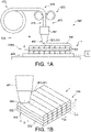
- Fig. 1a schematically depicts some aspects of the 3D printer.
- Reference 500 indicates a 3D printer.
- Reference 530 indicates the functional unit configured to 3D print, especially FDM 3D printing; this reference may also indicate the 3D printing stage unit.
- the printer head for providing 3D printed material such as a FDM 3D printer head is schematically depicted.
- Reference 501 indicates the printer head.
- the 3D printer of the present invention may especially include a plurality of printer heads, though other embodiments are also possible.
- Reference 502 indicates a printer nozzle.
- the 3D printer of the present invention may especially include a plurality of printer nozzles, though other embodiments are also possible.
- Reference 321 indicates a filament of printable 3D printable material (such as indicated above). For the sake of clarity, not all features of the 3D printer have been depicted, only those that are of especial relevance for the present invention (see further also below).
- the 3D printer 500 is configured to generate a 3D item 1 by layer-wise depositing on a receiver item 550, which may in embodiments at least temporarily be cooled, a plurality of filaments 321 wherein each filament 310 comprises 3D printable material 201, such as having a melting point T m .
- the 3D printable material 201 may be deposited on a substrate 1550 (during the printing stage).
- the 3D printer 500 is configured to heat the filament material upstream of the printer nozzle 502. This may e.g. be done with a device comprising one or more of an extrusion and/or heating function. Such device is indicated with reference 573, and is arranged upstream from the printer nozzle 502 (i.e. in time before the filament material leaves the printer nozzle 502).
- the printer head 501 may (thus) include a liquefier or heater.
- Reference 201 indicates printable material. When deposited, this material is indicated as (3D) printed material, which is indicated with reference 202.
- Reference 572 indicates a spool or roller with material, especially in the form of a wire, which may be indicated as filament 320.
- the 3D printer 500 transforms this in a filament 321 downstream of the printer nozzle which becomes a layer 322 on the receiver item or on already deposited printed material.
- the diameter of the filament 321 downstream of the nozzle is reduced relative to the diameter of the filament 322 upstream of the printer head.
- the printer nozzle is sometimes (also) indicated as extruder nozzle.
- a 3D item 1 may be formed.
- Reference 575 indicates the filament providing device, which here amongst others include the spool or roller and the driver wheels, indicated with reference 576.
- Reference A indicates a longitudinal axis or filament axis.
- Reference C schematically depicts a control system, such as especially a temperature control system configured to control the temperature of the receiver item 550.
- the control system C may include a heater which is able to heat the receiver item 550 to at least a temperature of 50 °C, but especially up to a range of about 350 °C, such as at least 200 °C.
- the receiver plate may also be moveable in one or two directions in the x-y plane (horizontal plane). Further, alternatively or additionally, in embodiments the receiver plate may also be rotatable about z axis (vertical). Hence, the control system may move the receiver plate in one or more of the x-direction, y-direction, and z-direction.
- the printer can have a head can also rotate during printing.
- Such a printer has an advantage that the printed material cannot rotate during printing.
- Layers are indicated with reference 322, and have a layer height H and a layer width W.
- the 3D printable material is not necessarily provided as filament 320 to the printer head. Further, the filament 320 may also be produced in the 3D printer 500 from pieces of 3D printable material.
- Reference D indicates the diameter of the nozzle (through which the 3D printable material 201 is forced).
- Fig. 1b schematically depicts in 3D in more detail the printing of the 3D item 1 under construction.
- the ends of the filaments 321 in a single plane are not interconnected, though in reality this may in embodiments be the case.
- Reference H indicates the height of a layer.
- Layers are indicated with reference 203.
- the layers have an essentially circular cross-section. Often, however, they may be flattened, such as having an outer shape resembling a flat oval tube or flat oval duct (i.e. a circular shaped bar having a diameter that is compressed to have a smaller height than width, wherein the sides (defining the width) are (still) rounded).
- Figs. 1a-1b schematically depict some aspects of a fused deposition modeling 3D printer 500, comprising (a) a first printer head 501 comprising a printer nozzle 502, (b) a filament providing device 575 configured to provide a filament 321 comprising 3D printable material 201 to the first printer head 501, and optionally (c) a receiver item 550.
- the first or second printable material or the first or second printed material are indicated with the general indications printable material 201 and printed material 202.
- the filament 321 with 3D printable material becomes, when deposited, layer 322 with 3D printed material 202.
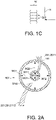
- Fig. 1c schematically depicts a stack of 3D printed layers 322, each having a layer height H and a layer width W. Note that in embodiments the layer width and/or layer height may differ for two or more layers 322.
- the filament of 3D printable material that is deposited leads to a layer having a height H (and width W). Depositing layer 322 after layer 322, the 3D item 1 is generated.
- Figs. 1a-1c show embodiments of amongst the method in general.
- Figs. 2a-2f schematically depict some aspects in more detail, wherein the core-shell 3D printing is further schematically elucidated.
- a core-shell nozzle 502 may be applied, see Figs. 2a , 2c and 2f , wherein different 3D printable materials 201 maybe introduced, to provide the 3D item 1 comprising 3D printed material 202, see Fig. 2d .
- Fig. 2a schematically depicts an embodiment printer nozzle 502, wherein the printer nozzle 502 comprises a core feed nozzle 5021 and a shell feed nozzle 5022 configured for providing the core-shell extrudate, wherein the core feed nozzle 5021 has a largest core nozzle width w11 and a smallest core nozzle width w12, wherein the shell feed nozzle 5022 has a largest shell nozzle width w21 and a smallest core nozzle width w22.
- Fig. 2b schematically depicts an embodiment of a core-shell type filament 201, but this schematic drawing may also be used to shown an embodiment of a core-shell type extrudate 321.
- the extrudate 321, which is of the core-shell type is herein also indicated as core-shell extrudate 1321.
- the dimensions may differ between the filament and the extrudate.
- the core is indicated with reference 321, and comprises core material 1321.
- the shell is indicated with reference 322, and comprises shell material 1322.
- the filament 320 shown may be printable 3D material 201, i.e. before depositing, or may refer to extrudate 321 escaping from the nozzle. Hence both reference 201 and 321 are applied.
- the core-shell filament 320 or extrudate 321 may in embodiments have a core diameter d1 selected from the range of 100 - 3000 ⁇ m.
- the shell thickness (d2) may be selected from the range of 100 - 2000 ⁇ m. In general, the shell thickness is smaller than the core diameter.
- the extrudate 321 comprises a core-shell extrudate 1321 comprising a core 2321 comprising a core material 2011, and a shell 2322 comprising a shell material 2012, wherein the core material 2011 and the shell material 2012 comprise different thermoplastic materials.
- Fig. 2c-2d very schematically depict that in embodiments the method may further comprise controlling the relative amounts of the first thermoplastic material 111 and the second thermoplastic material 112 during the 3D printing stage.
- the core material 2011 downstream from the nozzle comprises the first thermoplastic material 111. From right to left, it appears that 3D printing was started with only the first thermoplastic material. Thereafter, only the second thermoplastic material was deposited. Since then, the core-shell extrudate 1321 was provided and deposited as core-shell 3D printed material 202.
- the method may further comprise providing during one or more time periods of the 3D printing stage the core-shell extrudate 1321 and providing during one or more other time periods of the 3D printing stage extrudate comprising one of the first thermoplastic material 111 and the second thermoplastic material 112.
- Fig. 2d schematically depicts some layers 202 of the second thermoplastic material 112, some core-shell layers 3322 with both the first thermoplastic material 111 and the second thermoplastic material, wherein one is comprised by the core and the other is comprised by the shell, and again some layers 202 of the second thermoplastic material 112.
- Fig. 2e schematically depict a lowest layer 202 of the second thermoplastic material 112, a two core-shell layers 3322 with both the first thermoplastic material 111 and the second thermoplastic material, wherein one is comprised by the core and the other is comprised by the shell.
- thermoplastic material 111 is comprised by the core 2321 and the second thermoplastic material is comprised by the shell 2322.
- the core material 2011 comprises the first thermoplastic material 111 having the first glass transition temperature Tg1 of at maximum 0 °C and wherein the shell material 2012 comprises the second thermoplastic material having the second glass transition temperature Tg2 of at minimum 60 °C, and/or during one or more time periods of the 3D printing stage the core material 2011 comprises the second thermoplastic material having the second glass transition temperature Tg2 of at minimum 60 °C, and wherein the shell material 2012 comprises the first thermoplastic material 111 having the first glass transition temperature Tg1 of at maximum 0 °C
- Figs. 2d and 2e also schematically depict embodiments of a 3D item 1 comprising 3D printed material 202 wherein the 3D item 1 comprises a plurality of layers 322 of 3D printed material 202, wherein the plurality of layers 322 comprises one or more core-shell layer parts 3322, wherein each of the core-shell layer parts 3322 comprises a core 3321 comprising a core material 3021, and a shell 3322 comprising a shell material 3022, wherein the core material 3021 and the shell material 3022 comprise different thermoplastic materials selected from the group consisting of a first thermoplastic material 111 being an elastomeric material (having a first glass transition temperature Tg1 of at maximum 0 °C) and a second thermoplastic material 112 (having a second glass transition temperature Tg2 of at minimum 60 °C).
- a first thermoplastic material 111 being an elastomeric material (having a first glass transition temperature Tg1 of at maximum 0 °C) and a second thermoplastic material
- the relative amounts of the first thermoplastic material 111 and the second thermoplastic material 112 vary over a length L3 of one or more of the one or more core-shell layer parts 3322.
- This length L3 may be part of the layer or may be the entire layer.
- the plurality of layers 322 comprise one or more layer parts 3320 comprising one of the first thermoplastic material 111 and the second thermoplastic material 112.
- the thickness d22 may be reduced and a smoothening effect may occur (see also Figs. 3a-3c ).
- the printer nozzle 502 comprises a core feed nozzle 5021 and a shell feed nozzle 5022 configured for providing the core-shell extrudate 1321
- the core feed nozzle 5021 has a largest core nozzle width w11 and a smallest core nozzle width w12
- the shell feed nozzle 5022 has a largest shell nozzle width w21 and a smallest core
- the distances between the nozzles may be at minimum w52 and at maximum w51. Note that in such embodiments the shell thickness d2 of the extrudate downstream of the nozzle varies over the core, unlike the example in Fig. 2b (assuming to depict Fig. 2b an embodiment of an extrudate).
- FIG 3a schematically the cross-section of a structure made of core shell layers is shown. Core and jacket materials can be chosen as described herein.
- the surface is indicated with reference 205. Exposing the 3D printed material, or at least part of its surface 205 to the solvent comprising liquid, leads to a smooth(er) surface structure as schematically shown in Fig. 3b . An example of a treated surface is shown in Fig. 3c and is also shown in Fig. 4 .
- the product is printed in one go, which means the core material is one long fiber which is embedded in a shell matrix.
- d23 may at some parts between adjacent layer cores 3321 may be essentially zero ⁇ m. Hence, at some parts adjacent layer cores 3321 may be in physical contact with each other (or may even form a single phase, as the core materials may be the same).
- the distance d23 may be formed by the shell layer thickness d4 of one of the adjacent layer cores 3321 and d4 of the other of the adjacent layer cores 3321.
- Fig. 4 surface roughness of an object having a layer thickness of 800 ⁇ m (i.e. reference W in Fig. 2e ), measured using a DEKTAK 6M surface profiler before and after the treatment with acetone is shown.
- the surface roughness of a non-treated object U1 and U2, which relate to different surface parts
- the surface roughness indicated by line A i.e. after the treatment with acetone, shows that the roughness is reduced to about 30 ⁇ m.
- the item that was subjected to the acetone liquid showed less or no crack formation and essentially no delamination, neither deformation of the item.
- polypropylene was used as core material and ABS jacket material to print a cylinder as object.
- Acetone was used as solvent for surface smoothing.
- Acetone is a solvent for ABS however it does not dissolve PP.
- the outer surface (ABS) is partly dissolved and smoothened as shown in 4 (and schematically shown in Figs. 3b and 3c ).
- the inner part PP is not affected, as acetone is a non-solvent for PP.
- the skeleton (PP) remained unaffected during the smoothening and no delamination or cracking was observed.
- Fig. 5 schematically depicts an embodiment of a lamp or luminaire, indicated with reference 2, which comprises a light source 10 for generating light 11.
- the lamp may comprise a housing or shade or other element, which may comprise or be the 3D printed item 1.
- the present invention may produce 3D structures with ribbon like internal structures but with a relative smooth surface, at least having a roughness much smaller than of the ribbon like internal structure.
- substantially herein, such as “substantially consists”, will be understood by the person skilled in the art.
- the term “substantially” may also include embodiments with “entirely”, “completely”, “all”, etc. Hence, in embodiments the adjective substantially may also be removed.
- the term “substantially” may also relate to 90% or higher, such as 95% or higher, especially 99% or higher, even more especially 99.5% or higher, including 100%.
- the term “comprise” includes also embodiments wherein the term “comprises” means “consists of'.
- the term “and/or” especially relates to one or more of the items mentioned before and after "and/or”.
- a phrase “item 1 and/or item 2" and similar phrases may relate to one or more of item 1 and item 2.
- the term “comprising” may in an embodiment refer to “consisting of' but may in another embodiment also refer to "containing at least the defined species and optionally one or more other species”.
- the disclosure also provides a control system that may control the apparatus or device or system, or that may execute the herein described method or process. Yet further, the disclosure also provides a computer program product, when running on a computer which is functionally coupled to or comprised by the apparatus or device or system, controls one or more controllable elements of such apparatus or device or system.
- one or more of the first (printable or printed) material and second (printable or printed) material may contain fillers such as glass and fibers which do not have (to have) influence on the on T g or T m of the material(s).
Landscapes
- Chemical & Material Sciences (AREA)
- Engineering & Computer Science (AREA)
- Materials Engineering (AREA)
- Manufacturing & Machinery (AREA)
- Physics & Mathematics (AREA)
- Mechanical Engineering (AREA)
- Optics & Photonics (AREA)
Claims (11)
- Procédé de production d'un article 3D (1) au moyen d'une modélisation par dépôt en fusion, le procédé comprenant :- une phase d'impression 3D comprenant un dépôt en couches d'un extrudat (321) comprenant un matériau imprimable en 3D (201), dans lequel pendant au moins une partie de la phase d'impression 3D l'extrudat (321) comprend un extrudat à noyau-enveloppe (1321) comprenant un noyau (2321) comprenant un matériau de noyau (2011) et une enveloppe (2322) comprenant un matériau d'enveloppe (2012), pour fournir l'article 3D (1) comprenant un matériau imprimé en 3D (202), dans lequel l'article 3D (1) comprend une pluralité de couches (322) de matériau imprimé en 3D (202), dans lequel une ou plusieurs des couches (322) comprennent une ou plusieurs parties de couche à noyau-enveloppe (3322), dans lequel chacune des parties de couche à noyau-enveloppe (3322) comprend un noyau de couche (3321) comprenant le matériau de noyau (2011) et une enveloppe de couche (3322) comprenant le matériau d'enveloppe (2012), dans lequel l'article 3D (1) a une surface d'article (252) définie par au moins une partie du matériau imprimé en 3D (202) ;- une phase d'exposition comprenant l'exposition d'au moins une partie de la surface d'article (252) à un liquide (402), dans lequel le matériau de noyau (2011) a une solubilité de matériau de noyau SC1 pour le liquide (402) et dans lequel le matériau d'enveloppe (2012) a une solubilité de matériau d'enveloppe SS1 pour le liquide (402), dans lequel SC1<SS2, dans lequel :- le matériau de noyau (2011) comprend un ou plusieurs éléments parmi polycarbonate (PC), polyéthylène (PE), polyéthylène haute densité (PEHD), polypropylène (PP), polyoxyméthylène (POM), naphtalate de polyéthylène (PEN), résine de styrène-acrylonitrile (SAN), polysulfone (PSU), sulfure de polyphénylène (PPS) et téréphtalate de polyéthylène semi-cristallin (PET) ; et- le matériau d'enveloppe (2012) comprend un ou plusieurs éléments parmi acrylonitrile butadiène styrène (ABS), poly(méthacrylate de méthyle) (PMMA), polystyrène (PS) et copolymère acryliques de styrène (SMMA).
- Procédé selon la revendication 1, dans lequel le liquide (402) comprend une ou plusieurs éléments parmi acétone et méthyl-éthyl-cétone et dans lequel le liquide (402) est appliqué par un ou plusieurs parmi un écoulement du liquide (402) par-dessus au moins une partie de la surface d'article (252), pulvérisation du liquide (402) sur au moins une partie de la surface d'article (252), exposition d'au moins une partie de la surface d'article (252) à une vapeur comprenant le liquide (402) et immersion d'au moins une partie de la surface d'article (252) dans le liquide (402).
- Procédé selon l'une quelconque des revendications précédentes, dans lequel un ou plusieurs parmi la surface d'article (252) ou le liquide (402) pendant la phase d'exposition a une température d'au maximum 40 °C et dans lequel SC1/SS2≤0,5.
- Procédé selon l'une quelconque des revendications précédentes, dans lequel les couches (322) ont des hauteurs de couche (H) et des largeurs de couche (W), dans lequel les hauteurs de couche (H) sont plus petites que les largeurs de couche (W), dans lequel le procédé comprend la fourniture pendant la phase d'impression de la ou des couches (322) dans lequel l'enveloppe de couche (3322) a une épaisseur qui varie sur une circonférence (3331) du noyau de couche (3321), dans lequel l'épaisseur (d4) de l'enveloppe de couche (3322) dans la hauteur d'une couche respective (322) de la ou des couches (322) est plus petite que l'épaisseur (d22) de l'enveloppe de couche (3322) dans la largeur de la couche respective (322).
- Procédé selon l'une quelconque des revendications précédentes, dans lequel le matériau de noyau (2011) a une viscosité plus élevée que le matériau d'enveloppe (2012) à une température où tant le matériau de noyau (2011) que le matériau d'enveloppe (2012) sont fluides.
- Procédé selon l'une quelconque des revendications précédentes, dans lequel les couches (322) ont des hauteurs de couche (H) et des largeurs de couche (W), dans lequel pendant la phase d'impression une pression est appliquée à l'extrudat à noyau-enveloppe (1321) sur un substrat (1550) pour fournir aux couches (322) de matériau imprimé en 3D (202) sur le substrat (1550) des hauteurs de couche (H) plus petites que les largeurs de couche (W).
- Procédé selon l'une quelconque des revendications précédentes, comprenant en outre l'utilisation d'une buse d'imprimante (502), dans lequel la buse d'imprimante (502) comprend une buse d'alimentation de noyau (5021) et une buse d'alimentation d'enveloppe (5022) configurées pour fournir l'extrudat à noyau-enveloppe (1321), dans lequel la buse d'alimentation de noyau (5021) a une largeur de buse de noyau la plus grande (w11) et une largeur de buse de noyau la plus petite (w12), dans lequel la buse d'alimentation d'enveloppe (5022) a une largeur de buse d'enveloppe la plus grande (w21) et une largeur de buse de noyau la plus petite (w22), dans lequel w21 >w22, w21 >w11, w21>w12 et dans lequel w12≥w11.
- Procédé selon la revendication 7, le procédé comprenant l'application d'une imprimante 3D de modélisation par dépôt en fusion (500), comprenant (a) la buse d'imprimante (502) et (b) un substrat (1550), dans lequel l'imprimante 3D de modélisation par dépôt en fusion (500) est configurée pour fournir le matériau imprimable en 3D (201) au substrat (1550), dans lequel la buse (502) et le substrat (1550) sont configurés rotatifs l'un par rapport à l'autre et dans lequel le procédé comprend en outre le maintien de la buse (502) et du substrat (1550) dans une configuration telle que la largeur de buse de noyau la plus grande (w11) est configurée perpendiculaire à une direction d'impression 3D pendant au moins une partie de la phase d'impression.
- Procédé selon l'une quelconque des revendications précédentes, comprenant en outre l'exposition d'au moins une partie de la surface d'article (252) au liquide (402) jusqu'à ce qu'une rugosité moyenne prédéterminée de surface (Ra) d'une surface (205) de l'article 3D soit obtenue, dans lequel la rugosité moyenne prédéterminée de surface (Ra) est égale ou inférieure à 5 µm pour une zone d'au moins 25 mm2.
- Article 3D (1) comprenant un matériau imprimé en 3D (202), dans lequel l'article 3D (1) comprend une pluralité de couches (322) de matériau imprimé en 3D (202), dans lequel une ou plusieurs des couches (322) comprennent une ou plusieurs parties de couche à noyau-enveloppe (3322), dans lequel chacune des parties de couche à noyau-enveloppe (3322) comprend un noyau de couche (3321) comprenant le matériau de noyau (2011) et une enveloppe de couche (3322) comprenant le matériau d'enveloppe (2012), dans lequel l'article 3D (1) a une surface d'article (252) définie par au moins une partie du matériau imprimé en 3D (202), dans lequel l'enveloppe de couche (3322) a une épaisseur de couche (d22) au niveau de la surface d'article (252), dans lequel l'enveloppe de couche (3322) a une épaisseur de couche intermédiaire (d4) entre des couches adjacentes (322), dans lequel l'épaisseur moyenne de couche (d3) est plus grande que l'épaisseur de couche intermédiaire (d4), dans lequel :- le matériau de noyau (2011) comprend un ou plusieurs éléments parmi polycarbonate (PC), polyéthylène (PE), polyéthylène haute densité (PEHD), polypropylène (PP), polyoxyméthylène (POM), naphtalate de polyéthylène (PEN), résine de styrène-acrylonitrile (SAN), polysulfone (PSU), sulfure de polyphénylène (PPS) et téréphtalate de polyéthylène semi-cristallin (PET) ; et- le matériau d'enveloppe (2012) comprend un ou plusieurs éléments parmi acrylonitrile butadiène styrène (ABS), poly(méthacrylate de méthyle) (PMMA), polystyrène (PS) et copolymère acryliques de styrène (SMMA),dans lequel le matériau de noyau (2011) a une solubilité de matériau de noyau SC1 pour un liquide (402) et dans lequel le matériau d'enveloppe (2012) a une solubilité de matériau d'enveloppe SS1 pour le liquide (402), dans lequel SC1<SS2 etdans lequel la surface d'article 3D (252) a une rugosité moyenne de surface (Ra), la rugosité moyenne de surface (Ra) étant égale ou inférieure à 5 µm pour une zone d'au moins 25 mm2.
- Dispositif d'éclairage (1000) comprenant l'article 3D (1) selon la revendication 10, dans lequel l'article 3D (1) est configuré en tant qu'un ou plusieurs parmi au moins une partie d'un logement de dispositif d'éclairage, une paroi d'une chambre d'éclairage et un élément optique.
Applications Claiming Priority (2)
| Application Number | Priority Date | Filing Date | Title |
|---|---|---|---|
| EP18192205 | 2018-09-03 | ||
| PCT/EP2019/073225 WO2020048889A1 (fr) | 2018-09-03 | 2019-08-30 | Procédé d'impression permettant d'imprimer par dépôt de filament fondu des surfaces lisses d'articles |
Publications (2)
| Publication Number | Publication Date |
|---|---|
| EP3847002A1 EP3847002A1 (fr) | 2021-07-14 |
| EP3847002B1 true EP3847002B1 (fr) | 2022-04-06 |
Family
ID=63490301
Family Applications (1)
| Application Number | Title | Priority Date | Filing Date |
|---|---|---|---|
| EP19759001.1A Active EP3847002B1 (fr) | 2018-09-03 | 2019-08-30 | Procédé d'impression pour l'impression fdm de surfaces lisses d'articles |
Country Status (5)
| Country | Link |
|---|---|
| US (1) | US11718017B2 (fr) |
| EP (1) | EP3847002B1 (fr) |
| JP (1) | JP7036987B2 (fr) |
| CN (1) | CN112638620B (fr) |
| WO (1) | WO2020048889A1 (fr) |
Families Citing this family (16)
| Publication number | Priority date | Publication date | Assignee | Title |
|---|---|---|---|---|
| US12291823B2 (en) * | 2015-04-15 | 2025-05-06 | Robert A. Flitsch | Methods, materials and apparatus for mobile additive manufacturing of advanced structures and roadways |
| EP3765547B1 (fr) * | 2018-03-13 | 2025-08-13 | Eastman Chemical Company | Matériaux de construction pour des applications de fabrication additive |
| CN112888550A (zh) * | 2018-10-01 | 2021-06-01 | 昕诺飞控股有限公司 | 用于以相对于建筑板小于45°的倾斜角度打印物体的方法 |
| US20230158733A1 (en) * | 2020-04-16 | 2023-05-25 | Signify Holding B.V. | Luminaire with texture perforation |
| US12472681B2 (en) | 2020-08-06 | 2025-11-18 | Signify Holding B.V. | Mechanically stable core-shell FDM prints containing porous core |
| EP4192670B1 (fr) | 2020-08-06 | 2024-10-09 | Signify Holding B.V. | Procédé et objets obtenus par impression à l'aide d'un tube creux en continu utilisant le modelage par dépôt en fusion |
| CN116529054A (zh) * | 2020-11-13 | 2023-08-01 | 昕诺飞控股有限公司 | Fff制造的光反射表面 |
| KR20230121613A (ko) * | 2020-12-14 | 2023-08-18 | 롬 앤드 하스 캄파니 | 향상된 층간 접착력을 갖는 3d 프린팅 |
| WO2022211777A1 (fr) | 2021-03-29 | 2022-10-06 | Hewlett-Packard Development Company, L.P. | Fabrication d'objets imprimés en 3d |
| WO2022269143A1 (fr) * | 2021-06-22 | 2022-12-29 | Safran Reosc | Procédé de fabrication de miroir par impression 3d |
| WO2023031099A1 (fr) * | 2021-09-02 | 2023-03-09 | Signify Holding B.V. | Méthode et appareil de production d'un article 3d avec une buse double coeur-enveloppe fdm |
| JP2023080444A (ja) * | 2021-11-30 | 2023-06-09 | 東レ・モノフィラメント株式会社 | ポリフェニレンスルフィド樹脂モノフィラメント |
| DE102021214529A1 (de) | 2021-12-16 | 2023-06-22 | Volkswagen Aktiengesellschaft | Filament-Element für additive Fertigungsverfahren, Extrudiervorrichtung zur Herstellung eines Filament-Elements, Produktionsvorrichtung zur additiven Herstellung von 3D-Bauteilen |
| JP2023173061A (ja) * | 2022-05-25 | 2023-12-07 | セイコーエプソン株式会社 | 成形型の製造方法、および成形型 |
| JP7794086B2 (ja) * | 2022-07-28 | 2026-01-06 | トヨタ紡織株式会社 | 造形装置 |
| CN118991032B (zh) * | 2024-10-25 | 2024-12-31 | 内蒙古工业大学 | 一种方便脱模的3d打印工作台 |
Family Cites Families (17)
| Publication number | Priority date | Publication date | Assignee | Title |
|---|---|---|---|---|
| US7236166B2 (en) * | 2005-01-18 | 2007-06-26 | Stratasys, Inc. | High-resolution rapid manufacturing |
| CA3121870A1 (fr) | 2013-03-22 | 2014-09-25 | Markforged, Inc. | Impression tridimensionnelle |
| WO2015077262A1 (fr) | 2013-11-19 | 2015-05-28 | Guill Tool & Engineering | Entrées d'impression 3d coextrudées, multicouche et multicomposant |
| US20170210063A1 (en) * | 2014-08-04 | 2017-07-27 | 3M Innovative Properties Company | Finishing system for 3d printed components |
| DE102014112227A1 (de) * | 2014-08-26 | 2016-03-03 | Continental Automotive Gmbh | Tank für eine Betriebsflüssigkeit für ein Kraftfahrzeug |
| WO2016037563A1 (fr) * | 2014-09-09 | 2016-03-17 | Jf Polymers (Suzhou) Co., Ltd. | Composition polymère destinée à être utilisée comme matériau de support temporaire au cours d'une fabrication additive basée sur une extrusion |
| US11566349B2 (en) * | 2015-03-27 | 2023-01-31 | The United States Of America As Represented By The Secretary Of The Army | High strength 3D-printed polymer structures and methods of formation |
| EP3344442B1 (fr) | 2015-09-04 | 2020-04-29 | SABIC Global Technologies B.V. | Compositions de poudre, procédé de préparation d'articles et de revêtements à partir des compositions de poudre, et articles ainsi préparés |
| JP2017207549A (ja) | 2016-05-16 | 2017-11-24 | キヤノン株式会社 | 画像形成装置 |
| CN105881913B (zh) * | 2016-06-08 | 2018-07-27 | 珠海天威飞马打印耗材有限公司 | 三维打印机、打印方法及三维物体 |
| WO2018015192A1 (fr) | 2016-07-21 | 2018-01-25 | Philips Lighting Holding B.V. | Procédé et matériaux pour améliorer l'adhérence à un lit d'impression pour des objets imprimés par fdm |
| US11207831B2 (en) * | 2016-12-08 | 2021-12-28 | President And Fellows Of Harvard College | 3D printed core-shell filament and method of 3D printing a core-shell filament |
| JP2018119026A (ja) | 2017-01-23 | 2018-08-02 | キヤノン株式会社 | 造形材料、および、立体物の製造方法 |
| US10899940B2 (en) | 2017-01-25 | 2021-01-26 | Xerox Corporation | Interlayer printing process |
| EP3363619B1 (fr) | 2017-02-21 | 2020-01-22 | Signify Holding B.V. | Luminaires imprimés en 3d au moyen de fibres optiques |
| CN110382205B (zh) * | 2017-03-09 | 2021-10-22 | 昕诺飞控股有限公司 | 用于打印光滑fdm 3d物品的芯-壳型丝 |
| CN110637113A (zh) | 2017-04-27 | 2019-12-31 | 科思创有限公司 | 用于3-d打印的结构化长丝 |
-
2019
- 2019-08-30 US US17/272,617 patent/US11718017B2/en active Active
- 2019-08-30 JP JP2021512233A patent/JP7036987B2/ja active Active
- 2019-08-30 EP EP19759001.1A patent/EP3847002B1/fr active Active
- 2019-08-30 CN CN201980057421.9A patent/CN112638620B/zh active Active
- 2019-08-30 WO PCT/EP2019/073225 patent/WO2020048889A1/fr not_active Ceased
Also Published As
| Publication number | Publication date |
|---|---|
| CN112638620B (zh) | 2023-05-23 |
| EP3847002A1 (fr) | 2021-07-14 |
| JP2021528294A (ja) | 2021-10-21 |
| CN112638620A (zh) | 2021-04-09 |
| WO2020048889A1 (fr) | 2020-03-12 |
| US11718017B2 (en) | 2023-08-08 |
| JP7036987B2 (ja) | 2022-03-15 |
| US20210339463A1 (en) | 2021-11-04 |
Similar Documents
| Publication | Publication Date | Title |
|---|---|---|
| EP3847002B1 (fr) | Procédé d'impression pour l'impression fdm de surfaces lisses d'articles | |
| JP7113839B2 (ja) | 滑らかなfdm3d物品を印刷するためのコア-シェルフィラメント | |
| EP3102391B1 (fr) | Moule obtenue par modélisation par dépôt de fil en fusion pour le moulage et la réplication d'objets, procédé pour sa fabrication et système de modélisation en 3d par dépôt de fil en fusion | |
| EP3544792B1 (fr) | Article revêtu de poudre imprimé par le procédé fdm, procédé et dispositif de fabrication associés | |
| US12162208B2 (en) | Method for printing objects with inclination angles less than 45° with respect to building plate | |
| EP3774288B1 (fr) | Polymère réticulé chargé de particules de polymères pour des articles imprimés en 3d | |
| EP4192670B1 (fr) | Procédé et objets obtenus par impression à l'aide d'un tube creux en continu utilisant le modelage par dépôt en fusion | |
| US20210138721A1 (en) | Printed structure with metallic appearance | |
| WO2020064375A1 (fr) | Matériau imprimé par fdm résistant à la fissuration induite par un solvant | |
| EP3642011B1 (fr) | Tête d'imprimante pour impression 3d | |
| US11828438B2 (en) | Printing structures with openings in a side surface |
Legal Events
| Date | Code | Title | Description |
|---|---|---|---|
| STAA | Information on the status of an ep patent application or granted ep patent |
Free format text: STATUS: UNKNOWN |
|
| STAA | Information on the status of an ep patent application or granted ep patent |
Free format text: STATUS: THE INTERNATIONAL PUBLICATION HAS BEEN MADE |
|
| PUAI | Public reference made under article 153(3) epc to a published international application that has entered the european phase |
Free format text: ORIGINAL CODE: 0009012 |
|
| STAA | Information on the status of an ep patent application or granted ep patent |
Free format text: STATUS: REQUEST FOR EXAMINATION WAS MADE |
|
| 17P | Request for examination filed |
Effective date: 20210406 |
|
| AK | Designated contracting states |
Kind code of ref document: A1 Designated state(s): AL AT BE BG CH CY CZ DE DK EE ES FI FR GB GR HR HU IE IS IT LI LT LU LV MC MK MT NL NO PL PT RO RS SE SI SK SM TR |
|
| GRAP | Despatch of communication of intention to grant a patent |
Free format text: ORIGINAL CODE: EPIDOSNIGR1 |
|
| STAA | Information on the status of an ep patent application or granted ep patent |
Free format text: STATUS: GRANT OF PATENT IS INTENDED |
|
| DAV | Request for validation of the european patent (deleted) | ||
| DAX | Request for extension of the european patent (deleted) | ||
| INTG | Intention to grant announced |
Effective date: 20211029 |
|
| GRAS | Grant fee paid |
Free format text: ORIGINAL CODE: EPIDOSNIGR3 |
|
| GRAA | (expected) grant |
Free format text: ORIGINAL CODE: 0009210 |
|
| STAA | Information on the status of an ep patent application or granted ep patent |
Free format text: STATUS: THE PATENT HAS BEEN GRANTED |
|
| AK | Designated contracting states |
Kind code of ref document: B1 Designated state(s): AL AT BE BG CH CY CZ DE DK EE ES FI FR GB GR HR HU IE IS IT LI LT LU LV MC MK MT NL NO PL PT RO RS SE SI SK SM TR |
|
| REG | Reference to a national code |
Ref country code: GB Ref legal event code: FG4D |
|
| REG | Reference to a national code |
Ref country code: CH Ref legal event code: EP |
|
| REG | Reference to a national code |
Ref country code: AT Ref legal event code: REF Ref document number: 1480919 Country of ref document: AT Kind code of ref document: T Effective date: 20220415 |
|
| REG | Reference to a national code |
Ref country code: IE Ref legal event code: FG4D |
|
| REG | Reference to a national code |
Ref country code: DE Ref legal event code: R096 Ref document number: 602019013517 Country of ref document: DE |
|
| REG | Reference to a national code |
Ref country code: LT Ref legal event code: MG9D |
|
| REG | Reference to a national code |
Ref country code: NL Ref legal event code: MP Effective date: 20220406 |
|
| REG | Reference to a national code |
Ref country code: AT Ref legal event code: MK05 Ref document number: 1480919 Country of ref document: AT Kind code of ref document: T Effective date: 20220406 |
|
| PG25 | Lapsed in a contracting state [announced via postgrant information from national office to epo] |
Ref country code: NL Free format text: LAPSE BECAUSE OF FAILURE TO SUBMIT A TRANSLATION OF THE DESCRIPTION OR TO PAY THE FEE WITHIN THE PRESCRIBED TIME-LIMIT Effective date: 20220406 |
|
| PG25 | Lapsed in a contracting state [announced via postgrant information from national office to epo] |
Ref country code: SE Free format text: LAPSE BECAUSE OF FAILURE TO SUBMIT A TRANSLATION OF THE DESCRIPTION OR TO PAY THE FEE WITHIN THE PRESCRIBED TIME-LIMIT Effective date: 20220406 Ref country code: PT Free format text: LAPSE BECAUSE OF FAILURE TO SUBMIT A TRANSLATION OF THE DESCRIPTION OR TO PAY THE FEE WITHIN THE PRESCRIBED TIME-LIMIT Effective date: 20220808 Ref country code: NO Free format text: LAPSE BECAUSE OF FAILURE TO SUBMIT A TRANSLATION OF THE DESCRIPTION OR TO PAY THE FEE WITHIN THE PRESCRIBED TIME-LIMIT Effective date: 20220706 Ref country code: LT Free format text: LAPSE BECAUSE OF FAILURE TO SUBMIT A TRANSLATION OF THE DESCRIPTION OR TO PAY THE FEE WITHIN THE PRESCRIBED TIME-LIMIT Effective date: 20220406 Ref country code: HR Free format text: LAPSE BECAUSE OF FAILURE TO SUBMIT A TRANSLATION OF THE DESCRIPTION OR TO PAY THE FEE WITHIN THE PRESCRIBED TIME-LIMIT Effective date: 20220406 Ref country code: GR Free format text: LAPSE BECAUSE OF FAILURE TO SUBMIT A TRANSLATION OF THE DESCRIPTION OR TO PAY THE FEE WITHIN THE PRESCRIBED TIME-LIMIT Effective date: 20220707 Ref country code: FI Free format text: LAPSE BECAUSE OF FAILURE TO SUBMIT A TRANSLATION OF THE DESCRIPTION OR TO PAY THE FEE WITHIN THE PRESCRIBED TIME-LIMIT Effective date: 20220406 Ref country code: ES Free format text: LAPSE BECAUSE OF FAILURE TO SUBMIT A TRANSLATION OF THE DESCRIPTION OR TO PAY THE FEE WITHIN THE PRESCRIBED TIME-LIMIT Effective date: 20220406 Ref country code: BG Free format text: LAPSE BECAUSE OF FAILURE TO SUBMIT A TRANSLATION OF THE DESCRIPTION OR TO PAY THE FEE WITHIN THE PRESCRIBED TIME-LIMIT Effective date: 20220706 Ref country code: AT Free format text: LAPSE BECAUSE OF FAILURE TO SUBMIT A TRANSLATION OF THE DESCRIPTION OR TO PAY THE FEE WITHIN THE PRESCRIBED TIME-LIMIT Effective date: 20220406 |
|
| PG25 | Lapsed in a contracting state [announced via postgrant information from national office to epo] |
Ref country code: RS Free format text: LAPSE BECAUSE OF FAILURE TO SUBMIT A TRANSLATION OF THE DESCRIPTION OR TO PAY THE FEE WITHIN THE PRESCRIBED TIME-LIMIT Effective date: 20220406 Ref country code: PL Free format text: LAPSE BECAUSE OF FAILURE TO SUBMIT A TRANSLATION OF THE DESCRIPTION OR TO PAY THE FEE WITHIN THE PRESCRIBED TIME-LIMIT Effective date: 20220406 Ref country code: LV Free format text: LAPSE BECAUSE OF FAILURE TO SUBMIT A TRANSLATION OF THE DESCRIPTION OR TO PAY THE FEE WITHIN THE PRESCRIBED TIME-LIMIT Effective date: 20220406 Ref country code: IS Free format text: LAPSE BECAUSE OF FAILURE TO SUBMIT A TRANSLATION OF THE DESCRIPTION OR TO PAY THE FEE WITHIN THE PRESCRIBED TIME-LIMIT Effective date: 20220806 |
|
| REG | Reference to a national code |
Ref country code: DE Ref legal event code: R097 Ref document number: 602019013517 Country of ref document: DE |
|
| PG25 | Lapsed in a contracting state [announced via postgrant information from national office to epo] |
Ref country code: SM Free format text: LAPSE BECAUSE OF FAILURE TO SUBMIT A TRANSLATION OF THE DESCRIPTION OR TO PAY THE FEE WITHIN THE PRESCRIBED TIME-LIMIT Effective date: 20220406 Ref country code: SK Free format text: LAPSE BECAUSE OF FAILURE TO SUBMIT A TRANSLATION OF THE DESCRIPTION OR TO PAY THE FEE WITHIN THE PRESCRIBED TIME-LIMIT Effective date: 20220406 Ref country code: RO Free format text: LAPSE BECAUSE OF FAILURE TO SUBMIT A TRANSLATION OF THE DESCRIPTION OR TO PAY THE FEE WITHIN THE PRESCRIBED TIME-LIMIT Effective date: 20220406 Ref country code: EE Free format text: LAPSE BECAUSE OF FAILURE TO SUBMIT A TRANSLATION OF THE DESCRIPTION OR TO PAY THE FEE WITHIN THE PRESCRIBED TIME-LIMIT Effective date: 20220406 Ref country code: DK Free format text: LAPSE BECAUSE OF FAILURE TO SUBMIT A TRANSLATION OF THE DESCRIPTION OR TO PAY THE FEE WITHIN THE PRESCRIBED TIME-LIMIT Effective date: 20220406 Ref country code: CZ Free format text: LAPSE BECAUSE OF FAILURE TO SUBMIT A TRANSLATION OF THE DESCRIPTION OR TO PAY THE FEE WITHIN THE PRESCRIBED TIME-LIMIT Effective date: 20220406 |
|
| PLBE | No opposition filed within time limit |
Free format text: ORIGINAL CODE: 0009261 |
|
| STAA | Information on the status of an ep patent application or granted ep patent |
Free format text: STATUS: NO OPPOSITION FILED WITHIN TIME LIMIT |
|
| 26N | No opposition filed |
Effective date: 20230110 |
|
| PG25 | Lapsed in a contracting state [announced via postgrant information from national office to epo] |
Ref country code: MC Free format text: LAPSE BECAUSE OF FAILURE TO SUBMIT A TRANSLATION OF THE DESCRIPTION OR TO PAY THE FEE WITHIN THE PRESCRIBED TIME-LIMIT Effective date: 20220406 Ref country code: AL Free format text: LAPSE BECAUSE OF FAILURE TO SUBMIT A TRANSLATION OF THE DESCRIPTION OR TO PAY THE FEE WITHIN THE PRESCRIBED TIME-LIMIT Effective date: 20220406 |
|
| REG | Reference to a national code |
Ref country code: CH Ref legal event code: PL |
|
| PG25 | Lapsed in a contracting state [announced via postgrant information from national office to epo] |
Ref country code: LU Free format text: LAPSE BECAUSE OF NON-PAYMENT OF DUE FEES Effective date: 20220830 Ref country code: LI Free format text: LAPSE BECAUSE OF NON-PAYMENT OF DUE FEES Effective date: 20220831 Ref country code: CH Free format text: LAPSE BECAUSE OF NON-PAYMENT OF DUE FEES Effective date: 20220831 |
|
| REG | Reference to a national code |
Ref country code: BE Ref legal event code: MM Effective date: 20220831 |
|
| PG25 | Lapsed in a contracting state [announced via postgrant information from national office to epo] |
Ref country code: SI Free format text: LAPSE BECAUSE OF FAILURE TO SUBMIT A TRANSLATION OF THE DESCRIPTION OR TO PAY THE FEE WITHIN THE PRESCRIBED TIME-LIMIT Effective date: 20220406 |
|
| P01 | Opt-out of the competence of the unified patent court (upc) registered |
Effective date: 20230425 |
|
| PG25 | Lapsed in a contracting state [announced via postgrant information from national office to epo] |
Ref country code: IE Free format text: LAPSE BECAUSE OF NON-PAYMENT OF DUE FEES Effective date: 20220830 |
|
| PG25 | Lapsed in a contracting state [announced via postgrant information from national office to epo] |
Ref country code: BE Free format text: LAPSE BECAUSE OF NON-PAYMENT OF DUE FEES Effective date: 20220831 |
|
| PG25 | Lapsed in a contracting state [announced via postgrant information from national office to epo] |
Ref country code: IT Free format text: LAPSE BECAUSE OF FAILURE TO SUBMIT A TRANSLATION OF THE DESCRIPTION OR TO PAY THE FEE WITHIN THE PRESCRIBED TIME-LIMIT Effective date: 20220406 |
|
| PG25 | Lapsed in a contracting state [announced via postgrant information from national office to epo] |
Ref country code: CY Free format text: LAPSE BECAUSE OF FAILURE TO SUBMIT A TRANSLATION OF THE DESCRIPTION OR TO PAY THE FEE WITHIN THE PRESCRIBED TIME-LIMIT Effective date: 20220406 |
|
| PG25 | Lapsed in a contracting state [announced via postgrant information from national office to epo] |
Ref country code: MK Free format text: LAPSE BECAUSE OF FAILURE TO SUBMIT A TRANSLATION OF THE DESCRIPTION OR TO PAY THE FEE WITHIN THE PRESCRIBED TIME-LIMIT Effective date: 20220406 Ref country code: HU Free format text: LAPSE BECAUSE OF FAILURE TO SUBMIT A TRANSLATION OF THE DESCRIPTION OR TO PAY THE FEE WITHIN THE PRESCRIBED TIME-LIMIT; INVALID AB INITIO Effective date: 20190830 |
|
| PG25 | Lapsed in a contracting state [announced via postgrant information from national office to epo] |
Ref country code: MT Free format text: LAPSE BECAUSE OF FAILURE TO SUBMIT A TRANSLATION OF THE DESCRIPTION OR TO PAY THE FEE WITHIN THE PRESCRIBED TIME-LIMIT Effective date: 20220406 |
|
| PG25 | Lapsed in a contracting state [announced via postgrant information from national office to epo] |
Ref country code: BG Free format text: LAPSE BECAUSE OF FAILURE TO SUBMIT A TRANSLATION OF THE DESCRIPTION OR TO PAY THE FEE WITHIN THE PRESCRIBED TIME-LIMIT Effective date: 20220406 |
|
| PG25 | Lapsed in a contracting state [announced via postgrant information from national office to epo] |
Ref country code: BG Free format text: LAPSE BECAUSE OF FAILURE TO SUBMIT A TRANSLATION OF THE DESCRIPTION OR TO PAY THE FEE WITHIN THE PRESCRIBED TIME-LIMIT Effective date: 20220406 |
|
| PGFP | Annual fee paid to national office [announced via postgrant information from national office to epo] |
Ref country code: GB Payment date: 20250826 Year of fee payment: 7 |
|
| PGFP | Annual fee paid to national office [announced via postgrant information from national office to epo] |
Ref country code: FR Payment date: 20250825 Year of fee payment: 7 |
|
| PG25 | Lapsed in a contracting state [announced via postgrant information from national office to epo] |
Ref country code: TR Free format text: LAPSE BECAUSE OF FAILURE TO SUBMIT A TRANSLATION OF THE DESCRIPTION OR TO PAY THE FEE WITHIN THE PRESCRIBED TIME-LIMIT Effective date: 20220406 |
|
| PGFP | Annual fee paid to national office [announced via postgrant information from national office to epo] |
Ref country code: DE Payment date: 20251028 Year of fee payment: 7 |