EP3847047B1 - Dispositif de regulation d'un flux d'air pour une entree d'air d'un vehicule automobile - Google Patents
Dispositif de regulation d'un flux d'air pour une entree d'air d'un vehicule automobile Download PDFInfo
- Publication number
- EP3847047B1 EP3847047B1 EP19769845.9A EP19769845A EP3847047B1 EP 3847047 B1 EP3847047 B1 EP 3847047B1 EP 19769845 A EP19769845 A EP 19769845A EP 3847047 B1 EP3847047 B1 EP 3847047B1
- Authority
- EP
- European Patent Office
- Prior art keywords
- air
- flow
- housing
- duct
- sealing means
- Prior art date
- Legal status (The legal status is an assumption and is not a legal conclusion. Google has not performed a legal analysis and makes no representation as to the accuracy of the status listed.)
- Active
Links
Images

Classifications
-
- B—PERFORMING OPERATIONS; TRANSPORTING
- B60—VEHICLES IN GENERAL
- B60K—ARRANGEMENT OR MOUNTING OF PROPULSION UNITS OR OF TRANSMISSIONS IN VEHICLES; ARRANGEMENT OR MOUNTING OF PLURAL DIVERSE PRIME-MOVERS IN VEHICLES; AUXILIARY DRIVES FOR VEHICLES; INSTRUMENTATION OR DASHBOARDS FOR VEHICLES; ARRANGEMENTS IN CONNECTION WITH COOLING, AIR INTAKE, GAS EXHAUST OR FUEL SUPPLY OF PROPULSION UNITS IN VEHICLES
- B60K11/00—Arrangement in connection with cooling of propulsion units
- B60K11/02—Arrangement in connection with cooling of propulsion units with liquid cooling
- B60K11/04—Arrangement or mounting of radiators, radiator shutters, or radiator blinds
-
- B—PERFORMING OPERATIONS; TRANSPORTING
- B60—VEHICLES IN GENERAL
- B60K—ARRANGEMENT OR MOUNTING OF PROPULSION UNITS OR OF TRANSMISSIONS IN VEHICLES; ARRANGEMENT OR MOUNTING OF PLURAL DIVERSE PRIME-MOVERS IN VEHICLES; AUXILIARY DRIVES FOR VEHICLES; INSTRUMENTATION OR DASHBOARDS FOR VEHICLES; ARRANGEMENTS IN CONNECTION WITH COOLING, AIR INTAKE, GAS EXHAUST OR FUEL SUPPLY OF PROPULSION UNITS IN VEHICLES
- B60K11/00—Arrangement in connection with cooling of propulsion units
- B60K11/08—Air inlets for cooling; Shutters or blinds therefor
- B60K11/085—Air inlets for cooling; Shutters or blinds therefor with adjustable shutters or blinds
-
- B—PERFORMING OPERATIONS; TRANSPORTING
- B60—VEHICLES IN GENERAL
- B60K—ARRANGEMENT OR MOUNTING OF PROPULSION UNITS OR OF TRANSMISSIONS IN VEHICLES; ARRANGEMENT OR MOUNTING OF PLURAL DIVERSE PRIME-MOVERS IN VEHICLES; AUXILIARY DRIVES FOR VEHICLES; INSTRUMENTATION OR DASHBOARDS FOR VEHICLES; ARRANGEMENTS IN CONNECTION WITH COOLING, AIR INTAKE, GAS EXHAUST OR FUEL SUPPLY OF PROPULSION UNITS IN VEHICLES
- B60K11/00—Arrangement in connection with cooling of propulsion units
- B60K11/06—Arrangement in connection with cooling of propulsion units with air cooling
-
- B—PERFORMING OPERATIONS; TRANSPORTING
- B60—VEHICLES IN GENERAL
- B60K—ARRANGEMENT OR MOUNTING OF PROPULSION UNITS OR OF TRANSMISSIONS IN VEHICLES; ARRANGEMENT OR MOUNTING OF PLURAL DIVERSE PRIME-MOVERS IN VEHICLES; AUXILIARY DRIVES FOR VEHICLES; INSTRUMENTATION OR DASHBOARDS FOR VEHICLES; ARRANGEMENTS IN CONNECTION WITH COOLING, AIR INTAKE, GAS EXHAUST OR FUEL SUPPLY OF PROPULSION UNITS IN VEHICLES
- B60K11/00—Arrangement in connection with cooling of propulsion units
- B60K11/08—Air inlets for cooling; Shutters or blinds therefor
-
- B—PERFORMING OPERATIONS; TRANSPORTING
- B60—VEHICLES IN GENERAL
- B60Y—INDEXING SCHEME RELATING TO ASPECTS CROSS-CUTTING VEHICLE TECHNOLOGY
- B60Y2306/00—Other features of vehicle sub-units
- B60Y2306/09—Reducing noise
Definitions
- the invention relates to a device for regulating an air flow for an air intake of a motor vehicle and more specifically to a motor vehicle, and in particular an electric motor vehicle comprising such an air intake regulation device.
- a motor vehicle comprises an air inlet in the form of an opening located on the front face of said motor vehicle.
- the incoming air is used to enable heat exchange between the latter and the cooling system of the motor vehicle, said cooling system being located near the front face of said vehicle.
- the air entering the engine compartment of the motor vehicle is guided towards the cooling system of said motor vehicle to enable heat exchange between the incoming air and the heat exchanger of the cooling system. It is important to minimize losses of the air flow between the air inlet and the heat exchanger. Indeed, any air flow entering the interior of the vehicle, and escaping towards the engine compartment before having contributed to the heat exchange inside the motor vehicle, negatively influences the coefficient of air resistance of said motor vehicle.
- the air intake control device may comprise an air duct arranged downstream of the cooling system and configured to guide the air flow towards the exterior of the vehicle.
- a duct may be advantageous for generating a venturi effect downstream of the cooling unit so that a greater air flow can pass through the cooling system thereby improving thermal efficiency.
- conduits as known in the prior art are relatively leaky and air leaks, causing a reduction in the flow of incoming air, can quickly reduce the thermal performance of the cooling system.
- the motor fan unit of the cooling system is activated in order to ensure cooling of the battery and prevent it from overheating.
- such operation generates noise pollution for the user.
- the present invention seeks to overcome this drawback and proposes a device for regulating an air flow for an air intake of a motor vehicle, according to the characteristics of claim 1.
- the regulating device comprises several elements and at least one sealing means is arranged between at least two elements.
- the flap is used to close the flow duct and in particular the duct leading the air flow to the outside of the vehicle.
- the noise pollution thus generated during the recharging of the battery is contained inside the vehicle and can no longer be perceived outside the vehicle.
- the invention also relates to a vehicle comprising a device for regulating an air flow for an air inlet as claimed.
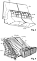
- FIG. 1 illustrates the regulating device 1 of an air flow for an air intake of a motor vehicle according to the invention.
- the regulating device 1 extends in a longitudinal (X), transverse (Y) and vertical (Z) direction, for example relative to the vehicle axes, as represented by the axes on the Figures 1 and 2 .
- the terms “downstream”, “upstream”, “in series” and “parallel” qualify the position of one component relative to another, according to the direction of flow of an air flow in a device 1 for regulating an air flow according to the present invention.
- the air flow regulating device 1 comprises a housing 2 corresponding to an envelope, or a sheath, thus defining, by its walls, a flow duct 4 with an air inlet 20 and an air outlet 22 in which an air flow flows.
- the housing 2 is made of flexible material in order to absorb the vibrations of the vehicle when it is moving, and of sufficiently strong material in order to carry elements such as heat exchangers, certain plastics for example polypropylene or polyamide-6 are suitable for such use.
- the air flow regulating device 1 further comprises a cooling unit 6.
- the cooling unit 6 comprises at least one heat exchanger intended to allow a heat exchange between the air flow and the fluid circulating within the heat exchanger.
- the cooling unit 6 here comprises a first and a second heat exchanger 8, 10.
- the first heat exchanger 8 corresponds for example to a condenser while the second heat exchanger 10 corresponds for example to a radiator.
- the cooling unit 6 further comprises a motor-fan unit 12 corresponding to a fan with blades and an associated motor so as to be able to suck in and release an air flow through the regulating device 1, even when the vehicle is stationary.
- the cooling unit 6 also comprises a supporting frame 62, visible on the figure 4 , corresponding to a rigid structure, more precisely a rigid plastic frame with four uprights delimiting a surface in which the heat exchangers 8, 10 and said motor-fan unit 12 are arranged.
- the housing 2 is fixed in a sealed manner to the supporting frame 62.
- the supporting frame 62 ensures the continuity of the flow duct 4, or in other words, the supporting frame 62 corresponds to a part of the flow duct 4.
- the air flow regulating device 1 further comprises a shut-off device 14 comprising a set of shut-off flaps 18 capable of pivoting in rotation so as to vary the flow rate of the air flow, said shut-off device 14 is arranged in the flow duct 4 upstream of the cooling unit 6 relative to the flow of the air flow.
- the shut-off device 14 further comprises a support frame 16 having bearings so as to support the shut-off flaps 18.
- Each shutter 18 comprises a rotation axis materialized by a journal which is inserted into the bearings of the support frame 16.
- the rotation axes allow the shutters 18 to pass from an opening configuration to a closing configuration.
- the opening configuration or in other words opening a shutter 18, amounts to placing (by rotation) the shutters 18 so that they oppose the passage of the air flow as little as possible while orienting it appropriately.
- the shutters 18 are arranged in a horizontal position, in other words they extend in a longitudinal (X) and transverse (Y) direction, and thus ensure that the flow rate for the air flow is maximum, the air inlet 20 being clear.
- the closing configuration or in other words closing a shutter 18, amounts to placing the shutters 18 so that they oppose each other by their surface frontal at most to the flow of the air flow F, in cooperation with the other shutters 18.
- the shutters 18 are arranged in a vertical position, in other words they extend in a transverse (Y) and vertical (Z) direction, and thus ensure that the flow rate for the air flow is minimal or even zero, the air inlet 20 being closed.
- the shutters 18 are able to adopt any intermediate position between these two configurations.
- the housing 2 is made in two parts, a first part 2a connecting the inlet of the housing 2, and therefore the air inlet 20 of the flow duct 4, where the closing device 14 is arranged, to the cooling unit 6, in particular to the supporting frame 62, and a second part 2b connecting the cooling unit 6, and more precisely the supporting frame 62, to the outlet of the housing 2 and therefore to the air outlet 22 of the flow duct 4.
- the parts 2a, 2b of the housing comprise fixing means 70 such as clips, hooks, screws with threaded rod/nuts with tapping, bolts, etc. of shapes complementary to the fixing means 70 arranged on the supporting frame 62. It is therefore understood that the supporting frame 62 ensures the continuity of the flow duct 4 between the two parts 2a, 2b of the housing 2.
- the parts 2a, 2b may also comprise means for fixing complementary shapes so that each part 2a, 2b can be fixed to each other. It is also conceivable to have a housing 2 in a single piece forming continuity of material between the air inlet 20 and the air outlet 22 of the flow duct 4.
- each part 2a, 2b may comprise two half-housings 2a 1 ,2a 2 ,2b 1 ,2b 2 .
- Each pair of half-housings 2a 1 ,2a 2 or 2b 1 ,2b 2 together form a part of the flow conduit 4.
- the first pair of half-boxes 2a 1 ,2a 2 as illustrated in figure 4 constitutes the part 2a of the housing 2, namely the part of the flow duct 4 connecting the inlet of the housing 2, in particular the air inlet 20 of the flow duct 4, where the closing device 14 is arranged, to the cooling unit 6, in particular to the supporting frame 62.
- the second pair of half-housings 2b 1 , 2b 2 illustrated in figure 3 , constitutes the second part 2b, namely the part of the flow duct 4 connecting the cooling unit 6, and more precisely the supporting frame 62, to the outlet of the housing 2 and therefore to the air outlet 22 of the flow duct 4.
- Each pair of half-housings 2a 1 , 2a 2 , or 2b 1 , 2b 2 comprises fixing means 72 of complementary shape such as clips where the female part is arranged on a half-housing 2a 1 and the male part is arranged on the other corresponding half-housing 2a 2 or vice versa.
- These fixing means 72 can be reversible so that the half-housings 2a 1 , 2a 2 , 2b 1 , 2b 2 are fixed to each other in a removable manner, in other words the half-housings 2a 1 , 2a 2 , 2b 1 , 2b 2 can be separated by a reversible connection.
- the housing 2 of the air flow regulating device 1 comprises at least one sealing means 64 to prevent any air leakage outside the flow duct 4.
- the sealing means 64 ensure that the entire air flow passing through the air inlet 20 of the flow duct 4 exits through the air outlet 22 of the flow duct 4.
- the sealing means 64 may be arranged at different locations of the regulating device 1. Indeed, each sealing means 64 is arranged at the interface of, that is to say between, two elements of the regulating device 1 that are disjointed, in other words, dissociable or not forming continuity of material. More precisely, in order to achieve optimum sealing, the sealing means 64 is arranged on the peripheral periphery of each element forming a portion of the dissociated flow duct 4. In other words, between two elements forming a part of the flow duct 4, a sealing means 64 is arranged on the peripheral bonding surface at the peripheral edges of each of these elements.
- the sealing means 64 can therefore be arranged between each half-housing 2a 1 , 2a 2 and 2b 1 , 2b 2 and/or between a part 2a or 2b of the housing 2 and the supporting frame 62 and/or between each half-housing 2a 1 , 2a 2 and 2b 1 , 2b 2 and the supporting frame 62. It is also possible to envisage positioning a sealing means 64 between the housing 2 and the support frame 16 of the closing device 14 at the air inlet 20.
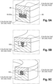
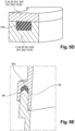
- the sealing means 64 may for example correspond to a seal, more precisely an O-ring 64c ( FIG.5C And FIG.5E ), to a 64a foam strip ( FIG.5A And FIG.5D ) or even to an overmolded elastomer lip 64b ( FIG.5B ).
- the sealing means 64 may be airtight or air and watertight.
- the subsequent description relating to the Figures 5A to 5E incorporates the concept of elements of the regulating device 1. It should be understood for the following that these elements correspond to two elements of the regulating device 1 which are separate, removable, separable, or assembled to each other by a reversible connection. These elements include the housing 2, each part 2a, 2b of the housing 2, each half-housing 2a 1 , 2a 2 , 2b 1 , 2b 2 , the support frame 16 of the shutter device 14 or the carrier frame 62 without any particular distinction or limitation.
- the sealing means 64 may correspond to a foam strip 64a arranged at the interface between two elements 2, 2a, 2b, 2a1, 2a2, 2b1, 2b2, 16, 62 of the regulating device.
- one of these elements say the first element, may comprise a groove 66 in which the foam strip 64b is arranged and the other element, say the second element, may comprise a protuberance 68 extending within the groove 66, that is to say in the direction of the bottom wall of the groove 66, and thus come to bear against the foam strip 64a, the foam strip 64a deforms so as to remain in contact with the protuberance 68 and the air flow can no longer pass through this cooperation.
- the foam strip 64a which may be a polyurethane foam, is particularly suitable for airtightness only.
- the foam strip 64a is arranged at the interface between two elements 2, 2a, 2b, 2a1, 2a2, 2b1, 2b2, 16, 62 of the regulating device 1 within a groove 66 present on the first element, and the second element comes directly into abutment against the foam strip 64a without protuberance, the foam strip 64a deforms so as to remain in contact with the second element 2, 2a, 2b, 2a1, 2a2, 2b1, 2b2, 16, 62 and the air flow can no longer pass through this cooperation.
- the sealing means 64 may correspond to an O-ring 64c arranged at the interface between two elements 2, 2a, 2b, 2a1, 2a2, 2b1, 2b2, 16, 62 of the regulating device 1.
- one of these elements say the first element, may comprise a groove 66 in which the O-ring 64c is arranged and the other element, say the second element, may come directly to bear against the O-ring 64c, the O-ring 64c deforms so as to remain in contact with the second element 2, 2a, 2b, 2a1, 2a2, 2b1, 2b2, 16, 62 and the air flow can no longer pass through this cooperation.
- the O-ring 64c which may be made of rubber or any other elastomer, is particularly suitable for air and water tightness.
- the second element can also include a protrusion 68 extending within the groove 66 and bearing against the O-ring 64c as illustrated in Figure 5E .
- the sealing means 64 may correspond to an overmolded lip 64b arranged at the interface between two elements 2, 2a, 2b, 2a1, 2a2, 2b1, 2b2, 16, 62 of the regulating device.
- one of these elements say the first element, may comprise a groove 66 and an overmolded lip 64b may be overmolded on the other element, say the second element, and come directly to bear against the bottom wall of the groove 66, that is to say against the first element, the overmolded lip 64b deforms so as to remain in contact with the first element 2, 2a, 2b, 2a1, 2a2, 2b1, 2b2, 16, 62 and the air flow can no longer pass through this cooperation.
- the overmolded lip 64b which may be made of rubber or any other elastomer (for example SEBS or polystyrene-b-poly(ethylene-butylene)-b-polystyrene), is particularly suitable for air and water sealing.
- SEBS polystyrene-b-poly(ethylene-butylene)-b-polystyrene
- the flow duct 4 comprises an air inlet 20 and an air outlet 22, the latter being composed of at least two separate ducts, the flap which will be described later being capable of closing each of said ducts.
- the air outlet 22 of the flow duct 4 comprises a clearing duct 24 arranged to guide the air flow towards the outside of the vehicle and a cooling duct 26 arranged to guide the air flow towards the engine compartment of the vehicle.
- the cooling duct 26 here corresponds to a duct where an opening 28 provided with a grid 30 is made within a wall of the housing 2 thus allowing the air flow to flow from the flow duct 4 towards the engine compartment.
- the cleaning duct 24 here corresponds to a duct where an opening 32 is made within a wall of the housing 2 thus allowing the air flow to flow from the flow duct 4 towards the outside of the vehicle.
- the device 1 for regulating an air flow comprises: further comprises a flap 34 arranged within the flow duct 4 downstream of the cooling unit 6 relative to the flow of the air flow.
- the flap 34 is of the drum type as illustrated in the figure 2 because, given that such a regulating device extends over a large part of the width of the vehicle (Y axis) and thus reaches more than one meter, the drum shutter, due to its structure which has better mechanical resistance, is better suited for such use.
- shutters may be envisaged such as a sliding shutter (also known as a sliding door) comprising a sliding door on which is arranged at least one rack and a gear complementary to the rack rotated about an axis by an actuator in order to set this shutter in motion, in particular according to a translational movement, according to an embodiment not illustrated.
- a sliding shutter also known as a sliding door
- a gear complementary to the rack rotated about an axis by an actuator in order to set this shutter in motion, in particular according to a translational movement, according to an embodiment not illustrated.
- the drum shutter 34 comprises a rotation axis 36 in the form of a shaft allowing the pivoting of the shutter 34.
- the drum shutter 34 further comprises three solid walls. Two side walls 38 arranged at the two opposite ends of the rotation axis 36, these two side walls 38 are parallel and are inscribed in a plane defined by the XZ axes perpendicular to the rotation axis 36, and a transverse wall 40 connecting the side walls to each other.
- the transverse wall 40 is inscribed in a plane defined by the XZ axes of curved shape allows the flow or drying up of the air flow in a duct 24, 26 of air outlet 22 of the flow duct 4 according to its positioning.
- the volume between the side walls 38, the transverse wall 40 and the axis of rotation 36 is unoccupied so that the air flow is able to pass between these elements as illustrated by the arrow F2 on the figure 2 .
- the transverse wall 40 of the drum shutter 34 is capable of closing the clearing duct 24 as illustrated in the figure 2
- the transverse wall 40 of the drum shutter 34 is also capable of closing the cooling duct 26 according to an embodiment not illustrated.
- the flap 34 match the shape of the walls of the housing 2 so as to ensure good sealing, the flap 34 may also further comprise elastomer lips 42 overmolded at the ends of the walls.
- the wall of the housing 2 where the cooling duct 26 is arranged is of substantially rounded shape, so that the curved transverse wall 40 of the flap 34 can completely close this outlet duct.
- the flap 34 When the vehicle is moving, the flap 34 is arranged to block the cooling duct 26, the air flow therefore passing through the cleaning duct 24. When the vehicle is parked at a terminal (the battery being recharged), the flap 34 is arranged to block the cleaning duct 24 cooling duct 26, the air flow therefore passing through the cooling duct 26 as illustrated in the figure. figure 2 .
- Shutter 34 is capable of adopting any intermediate position.
- the cooling unit 6 is inclined relative to the shutter device 14.
- the median planes of the cooling unit 6 and the shutter device 14 form an angle other than 0° (non-zero), in particular an angle comprised in a range between 10 and 80°, more precisely in a range between 30° and 60°.
- vanes 44 may prove advantageous for vanes 44 to be arranged upstream and/or downstream of the cooling unit 6 relative to the flow of the air flow.
- the vanes 44 correspond to air guides in the form of walls with rounded shapes defining corridors for the air flow in order to distribute the air flow F1 ( figure 2 ) over the entire surface of the heat exchangers 8, 10 of the unit cooling 6, this results in better thermal efficiency.
- the blades 44 may for example extend the continuity of the shutter flaps 18 of the shutter device 14 when they are in the opening configuration.
- the blades 44 may also have a general S shape with a leading edge corresponding to one end of the blade extending in a horizontal plane defined by the X and Y axes, a trailing edge substantially parallel to the leading edge but at a different height (Z) and an inclined section or ramp connecting the leading edge and the trailing edge which extends mainly along a vertical axis (Z).
- the invention is not limited to the shape of the blades 44 as long as they serve as a guide for the air flow, the blades 44 may for example be in the shape of a quarter circle.
- the first flat end portion of the blade 44 intended to be crossed by the air flow F1 corresponds to the leading edge and is flat.
- the second and last flat end portion intended to be crossed by the air flow F1 corresponds to the trailing edge and is also flat.
- the inclined section is not part of the leading and trailing edges.
- the passage section of the flow duct 4 increases from the air inlet 20 of the flow duct 4 to the cooling unit 6 and decreases from the cooling unit 6 to the air outlet 22 of the flow duct 4 according to the flow direction of the flow. air.
- the passage section of the flow duct 4 has at least one dimension (width and/or height) which increases as the length increases, or as one moves closer to the cooling unit 6 starting from the air inlet 20, depending on the direction of flow of the air flow.
- the passage section of the flow duct 4 has at least one dimension (width and/or height) which decreases as the length increases, or as one moves away from the cooling unit 6 as one moves closer to the air outlet 22, depending on the direction of flow of the air flow.
- sound-absorbing parts can be arranged within the housing 2, thus ensuring a sound-insulating coating of the flow duct 4 by eliminating or limiting the propagation of noise to the outside.
- the sound-absorbing part can for example correspond to a layer of polyurethane foam which has open or closed pores and preferably impregnated with a vinylidene copolymer, or to a cavity functioning as a Helmholtz resonator.
- the motor vehicle according to the invention therefore comprises an air intake provided with a grille and a device 1 for regulating this air intake.
- the air outlet 22 of the flow duct 4 comprises a clearing duct 24 arranged to lead the air flow towards the outside of the vehicle and a cooling duct 26 arranged to lead the air flow towards the engine compartment of the vehicle.
- the vehicle according to the invention may further comprise an additional inlet as well as an additional duct connecting said additional inlet with the cleaning duct leading the air flow towards the outside of the vehicle.
- This makes it possible to accentuate the venturi effect of the cleaning duct, thus increasing the flow rate of circulating air, thereby improving the thermal efficiency.
- the additional inlet may also be provided with a grid in order to prevent any foreign body (branches, leaves, etc.) from entering the additional duct.
Landscapes
- Engineering & Computer Science (AREA)
- Chemical & Material Sciences (AREA)
- Combustion & Propulsion (AREA)
- Transportation (AREA)
- Mechanical Engineering (AREA)
- Cooling, Air Intake And Gas Exhaust, And Fuel Tank Arrangements In Propulsion Units (AREA)
Description
- L'invention a pour objet un dispositif de régulation d'un flux d'air pour une entrée d'air d'un véhicule automobile et plus précisément ainsi qu'un véhicule automobile, et notamment un véhicule automobile électrique comprenant un tel dispositif de régulation d'entrée d'air.
- De manière générale, un véhicule automobile comprend une entrée d'air se présentant sous la forme d'une ouverture située sur la face avant dudit véhicule automobile. L'air entrant est utilisé pour permettre un échange de chaleur entre celui-ci et le système de refroidissement du véhicule automobile, ledit système de refroidissement étant situé à proximité de la face avant dudit véhicule. Plus précisément, l'air qui pénètre dans le compartiment moteur du véhicule automobile est guidé vers le système de refroidissement dudit véhicule automobile pour permettre un échange thermique entre l'air entrant et l'échangeur de chaleur du système de refroidissement. Il est important de minimiser les déperditions du flux d'air entre l'entrée d'air et l'échangeur de chaleur. En effet, tout flux d'air pénétrant à l'intérieur du véhicule, et s'échappant vers le compartiment moteur avant d'avoir contribué à l'échange de chaleur à l'intérieur du véhicule automobile, influence de manière négative le coefficient de résistance à l'air dudit véhicule automobile.
- Il est connu d'utiliser des guides d'air se présentant sous la forme d'un boîtier généralement en plastique ou autre matériau flexible reliant l'entrée d'air au système de refroidissement.
- Des dispositifs de régulation d'un flux d'air pour une entrée d'air d'un véhicule automobile sont notamment connus des documents
FR3013302 A1 FR2950574 A1 - Dans le cadre d'un véhicule électrique, le dispositif de régulation d'entrée d'air peut comprendre un conduit d'air agencé en aval du système de refroidissement et conçu pour guider le flux d'air vers l'extérieur du véhicule. Un tel conduit peut s'avérer avantageux pour générer un effet venturi en aval de l'unité de refroidissement de sorte qu'un plus grand débit d'air puisse passer au travers du système de refroidissement améliorant ainsi le rendement thermique.
- Un tel conduit présente cependant certains inconvénients. En effet, les conduits tels que connus dans l'art antérieur sont relativement peu étanches or des fuites d'air, provoquant une diminution du débit d'air entrant, peuvent vite réduire les performances thermiques du système de refroidissement. De plus, lors qu'un véhicule électrique est à l'arrêt et branché à une station, ou borne électrique, afin de recharger la batterie, le groupe moto ventilateur du système de refroidissement est activé afin d'assurer un refroidissement de la batterie et éviter que celle-ci ne surchauffe. Toutefois un tel fonctionnement génère des nuisances sonores pour l'utilisateur.
- La présente invention cherche à surmonter cet inconvénient et propose un dispositif de régulation d'un flux d'air pour une entrée d'air d'un véhicule automobile,selon les caractéristiques de la revendication 1. En d'autres termes, le dispositif de régulation comprend plusieurs éléments et au moins un moyen d'étanchéité est agencé entre au moins deux éléments.
- Le volet permet d'obturer le conduit d'écoulement et notamment le conduit menant le flux d'air vers l'extérieur du véhicule. Les nuisances sonores ainsi générées lors du rechargement de la batterie sont contenues à l'intérieur du véhicule et ne peuvent plus être perçues à l'extérieur du véhicule.
- D'autres modes de réalisation du dispositif de régulation selon l'invention sont tels que définis par les revendications dépendantes.
- D'autres modes de réalisation encore d'un dispositif de régulation d'entrée d'air ne faisant pas tous partie de l'invention et pris isolément ou en combinaison proposent que :
- le moyen d'étanchéité correspond à un joint ou une bande en mousse, ou bande de mousse ;
- le moyen d'étanchéité est étanche à l'air et à l'eau ;
- le dispositif de régulation comprend un volet agencé au sein du conduit d'écoulement en aval de l'unité de refroidissement par rapport à l'écoulement du flux d'air ;
- le conduit d'écoulement comprend une entrée et une sortie, la dite sortie étant composée d'au moins deux conduits distincts, ledit dispositif comprenant au moins un volet étant apte à obturer chacun desdits conduits ;
- un dispositif d'obturation comprenant un ensemble de volets d'obturation aptes à pivoter en rotation de manière à faire varier le débit de flux d'air, est agencé dans le conduit d'écoulement en amont de l'unité de refroidissement par rapport à l'écoulement du flux d'air ;
- l'unité de refroidissement est inclinée par rapport au dispositif d'obturation ;
- le volet est de type tambour ou coulissant;
- le conduit d'écoulement comprend une entrée et une sortie, la dite sortie étant composée d'au moins deux conduits distincts, le volet étant apte à obturer chacun desdits conduits ;
- un dispositif d'obturation comprenant un ensemble de volets d'obturation aptes à pivoter en rotation de manière à faire varier le débit de flux d'air, est agencé dans le conduit d'écoulement en amont de l'unité de refroidissement par rapport à l'écoulement du flux d'air ;
- l'unité de refroidissement est inclinée par rapport au dispositif d'obturation ;
- des aubes sont agencées en amont et/ou en aval de l'unité de refroidissement par rapport à l'écoulement du flux d'air ;
- les aubes s'étendent du dispositif d'obturation jusqu'à l'unité de refroidissement ;
- la section de passage du conduit d'écoulement s'agrandit depuis l'entrée jusqu'à l'unité de refroidissement et rétrécit depuis l'unité de refroidissement jusqu'à la sortie.
- L'invention concerne également un véhicule comprenant un dispositif de régulation d'un flux d'air pour une entrée d'air selon tel que revendiqué.
- D'autres modes de réalisation d'un véhicule non-couverts par l'invention pris isolément ou en combinaison proposent que :
- le véhicule comprend une entrée d'air, éventuellement dotée d'une calandre, la sortie du conduit d'écoulement comprend un conduit de débourrage agencé pour mener le flux d'air vers l'extérieur du véhicule et un conduit de refroidissement agencé pour mener le flux d'air vers le compartiment moteur du véhicule ;
- le véhicule comprend en outre une entrée d'air additionnelle et un conduit additionnel reliant ladite entrée additionnelle au conduit de débourrage.
- D'autres caractéristiques et avantages de l'invention apparaîtront à la lecture de la description qui va suivre. Celle-ci est purement illustrative et doit être lue en regard des dessins annexés sur lesquels :
- la
figure 1 illustre un dispositif de régulation d'un flux d'air selon l'invention selon une vue de profil, - la
figure 2 illustre une coupe du dispositif de régulation d'un flux d'air de lafigure 1 selon une vue de profil, - la
figure 3 illustre une partie du dispositif de régulation d'un flux d'air selon une vue en perspective, - la
figure 4 illustre le dispositif de régulation selon l'invention selon une vue en perspective, - Les
figures 5A - 5E illustrent différents modes de réalisation du moyen d'étanchéité. - La
figure 1 illustre le dispositif de régulation 1 d'un flux d'air pour une entrée d'air d'un véhicule automobile selon l'invention. Le dispositif de régulation 1 s'étend selon une direction longitudinale (X), transversale (Y) et verticale (Z), par exemple par rapport aux axes du véhicule, comme représenté par les axes sur lesfigures 1 et 2 . - Selon la présente invention, les termes "aval", "amont", "en série" et "parallèle" qualifient la position d'un composant par rapport à un autre, selon le sens de d'écoulement d'un flux d'air dans un dispositif de régulation 1 d'un flux d'air selon la présente invention.
- Le dispositif de régulation 1 d'un flux d'air selon l'invention comprend un boîtier 2 correspondant à une enveloppe, ou encore une gaine, définissant ainsi, de par ses parois, un conduit d'écoulement 4 avec une entrée d'air 20 et une sortie d'air 22 dans lequel s'écoule un flux d'air. Le boîtier 2 est réalisé en matériau flexible afin d'absorber les vibrations du véhicule lorsque celui-ci roule, et en matériau suffisamment résistant afin de porter des éléments tels que des échangeurs de chaleur, certains plastiques par exemple en polypropylène ou en polyamide-6 se prêtent à une telle utilisation.
- Le dispositif de régulation 1 d'un flux d'air selon l'invention comprend en outre une unité de refroidissement 6. L'unité de refroidissement 6 comprend au moins un échangeur de chaleur destiné à permettre un échange thermique entre le flux d'air et le fluide circulant au sein de l'échangeur de chaleur. Telle qu'illustrée en
figure 2 , l'unité de refroidissement 6 comprend ici un premier et un second échangeur de chaleur 8, 10. Le premier échangeur de chaleur 8 correspond par exemple à un condenseur tandis que le second échangeur de chaleur 10 correspond par exemple à un radiateur. L'unité de refroidissement 6 comprend en outre un groupe moto-ventilateur 12 correspondant à un ventilateur avec des pâles et un moteur associé de manière à pouvoir aspirer et relâcher un flux d'air à travers le dispositif de régulation 1, et ce même lorsque le véhicule est à l'arrêt. L'unité de refroidissement 6 comprend également un cadre porteur 62, visible sur lafigure 4 , correspondant à une structure rigide, plus précisément un cadre rigide en plastique avec quatre montants délimitant une surface dans laquelle sont agencés les échangeurs de chaleur 8,10 et ledit groupe moto-ventilateur 12. Afin de garantir la continuité du conduit d'écoulement 4, le boitier 2 est fixé de manière étanche au cadre porteur 62. Autrement dit le cadre porteur 62 assure la continuité du conduit d'écoulement 4, ou en d'autres termes, le cadre porteur 62 correspond à une partie du conduit d'écoulement 4. - Le dispositif de régulation 1 d'un flux d'air selon l'invention comprend en outre un dispositif d'obturation 14 comprenant un ensemble de volets d'obturation 18 aptes à pivoter en rotation de manière à faire varier le débit du flux d'air, ledit dispositif d'obturation 14 est agencé dans le conduit d'écoulement 4 en amont de l'unité de refroidissement 6 par rapport à l'écoulement du flux d'air. Le dispositif d'obturation 14 comprend en outre un cadre support 16 présentant des paliers de manière à porter les volets d'obturation 18.
- Chaque volet d'obturation 18 comprend un axe de rotation se matérialisant par un tourillon qui est inséré dans les paliers du cadre support 16. Les axes de rotation permettent aux volets d'obturation 18 de passer d'une configuration d'ouverture à une configuration de fermeture. La configuration d'ouverture, ou autrement dit ouvrir un volet d'obturation 18, revient à placer (par rotation) les volets d'obturation 18 de manière à ce qu'ils s'opposent le moins possible au passage du flux d'air tout en l'orientant de manière appropriée. Comme illustré sur la
figure 2 , dans la configuration d'ouverture, les volets d'obturation 18 sont agencés dans une position horizontale, en d'autres termes ils s'étendent selon une direction longitudinale (X) et transversale (Y), et assurent ainsi que le débit pour le flux d'air soit maximal, l'entrée d'air 20 d'air étant dégagée. La configuration de fermeture, ou autrement dit fermer un volet d'obturation 18, revient à placer les volets d'obturation 18 de manière à ce qu'ils s'opposent par leur surface frontale au maximum à l'écoulement du flux d'air F, en coopération avec les autres volets d'obturation 18. Dans cette configuration, les volets d'obturation 18 sont agencés dans une position verticale, autrement dit ils s'étendent selon une direction transversale (Y) et verticale (Z), et assurent ainsi que le débit pour le flux d'air soit minimal voire nul, l'entrée d'air 20 d'air étant obturée. Bien évidement, les volets d'obturation 18 sont aptes à adopter toute position intermédiaire entre ces deux configurations. - Le boîtier 2 selon l'invention, et tel qu'illustré aux
figures 1 et4 , est réalisé en deux parties, une première partie 2a reliant l'entrée du boîtier 2, et donc l'entrée d'air 20 du conduit découlement 4, où est agencée le dispositif d'obturation 14, à l'unité de refroidissement 6, notamment au cadre porteur 62, et une deuxième partie 2b reliant l'unité de refroidissement 6, et plus précisément le cadre porteur 62, à la sortie du boîtier 2 et donc à la sortie d'air 22 du conduit d'écoulement 4. Les parties 2a, 2b du boîtier comprennent des moyens de fixation 70 tels que des clips, crochets, vis avec tige filetée/écrous avec taraudage, boulons, etc. de formes complémentaires aux moyens de fixation 70 agencés sur le cadre porteur 62. On comprend donc que le cadre porteur 62 assure la continuité du conduit d'écoulement 4 entre les deux parties 2a,2b du boitier 2. - Selon d'autres modes de réalisation, les parties 2a,2b peuvent aussi comprendre des moyens de fixation de formes complémentaires de manière à ce que chaque partie 2a,2b puisse se fixer l'une à l'autre. Il est également envisageable d'avoir un boîtier 2 en une seule pièce monobloc formant continuité de matière entre l'entrée d'air 20 et la sortie d'air 22 du conduit d'écoulement 4.
- Le boitier 2, et plus précisément chaque partie 2a,2b, selon l'invention et tel qu'illustré en
figure 3 et 4 , peut comprendre deux demi-boitiers 2a1,2a2,2b1,2b2. Chaque paire de demi-boitier 2a1,2a2 ou 2b1,2b2 forment ensemble une partie du conduit d'écoulement 4. Autrement dit, la première paire de demi-boitier 2a1,2a2 telle qu'illustrée enfigure 4 , constitue, la partie 2a du boitier 2 à savoir la partie du conduit d'écoulement 4 reliant l'entrée du boîtier 2, notamment l'entrée d'air 20 du conduit d'écoulement 4, où est agencé le dispositif d'obturation 14, à l'unité de refroidissement 6, notamment au cadre porteur 62. La deuxième paire de demi boîtier 2b1,2b2, illustré enfigure 3 , constitue la deuxième partie 2b à savoir la partie du conduit d'écoulement 4 reliant l'unité de refroidissement 6, et plus précisément le cadre porteur 62, à la sortie du boîtier 2 et donc à la sortie d'air 22 du conduit d'écoulement 4. Chaque paire de demi-boitier 2a1,2a2, ou 2b1,2b2 comprend des moyens de fixation 72 de forme complémentaire tel que des clips où la partie femelle est agencé sur un demi-boitier 2a1 et la partie mâle est agencé sur l'autre demi-boitier 2a2 correspondant ou inversement. Ces moyens de fixation 72 peuvent être réversibles de sorte que les demi-boitiers 2a1,2a2,2b1,2b2 soient fixés l'un à l'autre de manière amovible, autrement dit que les demi-boitiers 2a1,2a2,2b1,2b2 soient dissociables par une liaison réversible. - Le boitier 2 du dispositif de régulation 1 d'un flux d'air selon l'invention comprend au moins un moyen d'étanchéité 64 pour éviter toute fuite d'air en dehors du conduit d'écoulement 4. Autrement dit, le ou les moyens d'étanchéité 64 assurent que l'intégralité du flux d'air passant par l'entrée d'air 20 du conduit d'écoulement 4 ressorte par la sortie d'air 22 du conduit d'écoulement 4. Le ou les moyens d'étanchéité 64 peuvent être agencés à différents endroits du dispositif de régulation 1. En effet, chaque moyen d'étanchéité 64 est agencé à l'interface de, c'est-à-dire entre, deux éléments du dispositif de régulation 1 disjoints, autrement dit, dissociables ou encore ne formant pas continuité de matière. Plus précisément, afin de réaliser une étanchéité optimale, le moyen d'étanchéité 64 est agencé sur le pourtour périphérique de chaque élément formant une partie du conduit d'écoulement 4 dissociés. Autrement dit, entre deux éléments formant une partie du conduit d'écoulement 4, un moyen d'étanchéité 64 est agencé sur la surface de liaison périphérique au niveau des bords périphériques de chacun de ces éléments.
- Le moyen d'étanchéité 64 peut donc être agencé entre chaque demi-boitier 2a1,2a2 et 2b1,2b2 et/ou entre une partie 2a ou 2b du boitier 2 et le cadre porteur 62 et/ou entre chaque demi-boitier 2a1,2a2 et 2b1,2b2 et le cadre porteur 62. Il est aussi possible d'envisager de positionner un moyen d'étanchéité 64 entre le boitier 2 et le cadre support 16 du dispositif d'obturation 14 au niveau de l'entrée d'air 20.
- Evidement l'invention ne se limite pas à l'agencement même des moyens d'étanchéité 64, il est possible de combiner les différents agencements cités ci-dessus.
- Comme illustré sur les
figures 5A à 5E, le moyen d'étanchéité 64 peut par exemple correspondre à un joint, plus précisément un joint torique 64c (FIG.5C etFIG.5E ), à une bande en mousse 64a (FIG.5A etFIG.5D ) ou encore à une lèvre en élastomère surmoulée 64b (FIG.5B ). - Le moyen d'étanchéité 64 peut être étanche à l'air ou à l'air et à l'eau.
- Afin de mieux décrire les moyens d'étanchéité, la description ultérieure portant sur les
figures 5A à 5E, incorpore la notion d'éléments du dispositif de régulation 1. Il faut comprendre pour la suite, que ces éléments correspondent à deux éléments du dispositif de régulation 1 disjoints, amovible, dissociable, ou encore assemblés l'un à l'autre par une liaison réversible. Dans ces éléments sont compris le boitier 2, chaque partie 2a,2b du boitier 2, chaque demi-boitier 2a1,2a2,2b1,2b2, le cadre support 16 du dispositif d'obturation 14 ou encore le cadre porteur 62 sans distinction ou limitation particulière. - Comme illustré en
figure 5A , le moyen d'étanchéité 64 peut corresponde à une bande en mousse 64a agencée à l'interface entre deux éléments 2,2a, 2b,2a1,2a2,2b1,2b2,16,62 du dispositif de régulation. Pour cela un de ces éléments, disons premier élément, peut comprendre une rainure 66 dans laquelle est agencée la bande en mousse 64b et l'autre élément, disons second élément, peut comprendre une protubérance 68 s'étendant au sein de la rainure 66, c'est-à-dire en direction de la paroi de fond de la rainure 66, et venir ainsi en appui contre la bande en mousse 64a, la bande en mousse 64a se déforme de manière à rester au contact de la protubérance 68 et le flux d'air ne peut plus passer à travers cette coopération. La bande en mousse 64a, pouvant être une mousse en polyuréthane, est particulièrement adapté pour une étanchéité à l'air uniquement. - Selon une variante illustrée en
figure 5D , la bande en mousse 64a est agencée à l'interface entre deux éléments 2, 2a, 2b, 2a1, 2a2, 2b1, 2b2, 16, 62 du dispositif de régulation 1 au sein d'une rainure 66 présente sur le premier élément, et le second élément vient directement en appui contre la bande en mousse 64a sans protubérance, la bande en mousse 64a se déforme de manière à rester au contact du second élément 2, 2a, 2b, 2a1, 2a2, 2b1, 2b2, 16, 62 et le flux d'air ne peut plus passer à travers cette coopération. - Comme illustré en
figure 5C , le moyen d'étanchéité 64 peut corresponde à un joint torique 64c agencé à l'interface entre deux éléments 2,2a,2b,2a1, 2a2,2b1,2b2,16,62 du dispositif de régulation 1. Pour cela un de ces éléments, disons premier élément, peut comprendre une rainure 66 dans laquelle est agencé le joint torique 64c et l'autre élément, disons second élément, peut venir directement en appui contre le joint torique 64c, le joint torique 64c se déforme de manière à rester au contact du deuxième élément 2, 2a, 2b, 2a1, 2a2, 2b1, 2b2, 16, 62 et le flux d'air ne peut plus passer à travers cette coopération. Le joint torique 64c, pouvant être en caoutchouc ou tout autre élastomère, est particulièrement adapté pour une étanchéité à l'air et à l'eau. Bien évidemment, le second élément peut aussi comprendre une protubérance 68 s'étendant au sein de la rainure 66 et venant en appui contre le joint torique 64c comme illustré enfigure 5E . - Comme illustré en
figure 5B , le moyen d'étanchéité 64 peut corresponde à une lèvre surmoulée 64b agencée à l'interface entre deux éléments 2, 2a, 2b, 2a1, 2a2, 2b1, 2b2, 16, 62 du dispositif de régulation. Pour cela un de ces éléments, disons premier élément, peut comprendre une rainure 66 et une lèvre surmoulée 64b peut être surmoulée sur l'autre élément, disons second élément, et venir directement en appui contre la paroi de fond de la rainure 66 c'est-à-dire contre le premier élément, la lèvre surmoulée 64b se déforme de manière à rester au contact du premier élément 2, 2a, 2b, 2a1, 2a2, 2b1, 2b2, 16, 62 et le flux d'air ne peut plus passer à travers cette coopération. La lèvre surmoulée 64b, pouvant être en caoutchouc ou tout autre élastomère (par exemple du SEBS ou polystyrène-b-poly(éthylène-butylène)-b-polystyrène), est particulièrement adapté pour une étanchéité à l'air et à l'eau. - Le conduit d'écoulement 4 comprend une entrée d'air 20 et une sortie d'air 22 cette dernière est composée d'au moins deux conduits distincts, le volet qui sera décrit ultérieurement étant apte à obturer chacun desdits conduits. La sortie d'air 22 du conduit d'écoulement 4 comprend un conduit de débourrage 24 agencé pour guider le flux d'air vers l'extérieur du véhicule et un conduit de refroidissement 26 agencé pour guider le flux d'air vers le compartiment moteur du véhicule. Comme illustré sur la
figure 3 , le conduit de refroidissement 26 correspond ici un conduit où une ouverture 28 dotée d'une grille 30 est réalisée au sein d'une paroi du boîtier 2 permettant ainsi au flux d'air de s'écouler du conduit d'écoulement 4 vers le compartiment moteur. Le conduit de débourrage 24 correspond ici à un conduit où une ouverture 32 est réalisée au sein d'une paroi du boîtier 2 permettant ainsi au flux d'air de s'écouler du conduit d'écoulement 4 vers l'extérieur du véhicule. - Le dispositif de régulation 1 d'un flux d'air selon l'invention comprend en outre comprend un volet 34 agencé au sein du conduit d'écoulement 4 en aval de l'unité de refroidissement 6 par rapport à l'écoulement du flux d'air. Le volet 34 est de type tambour comme illustré sur la
figure 2 car, étant donné qu'un tel dispositif de régulation s'étend sur une grande partie de la largeur du véhicule (Axe Y) pendant ainsi atteindre plus d'un mètre, le volet tambour, de par sa structure qui présente une meilleure résistance mécanique, est mieux adapté pour un tel usage. D'autres volets peuvent être envisageables tels qu'un volet coulissant (également connu sous l'appellation anglaise sliding door) comprenant une porte coulissante sur laquelle est agencée au moins une crémaillère et un engrenage complémentaire à la crémaillère mis en rotation autour d'un axe par un actionneur afin de mettre ce volet en mouvement, notamment selon un mouvement de translation, selon un mode de réalisation non illustré. - Le volet 34 tambour comprend un axe de rotation 36 sous la forme d'un arbre permettant le pivotement du volet 34. Le volet 34 tambour comprend en outre trois parois pleines. Deux parois latérales 38 agencées aux deux extrémités opposées de l'axe de rotation 36, ces deux parois latérales 38 sont parallèles et s'inscrivent dans un plan défini par les axes XZ perpendiculaire à l'axe de rotation 36, et une paroi transversale 40 reliant les parois latérales l'unes à l'autre. La paroi transversale 40 s'inscrit dans un plan défini par les axes XZ de forme galbée permet l'écoulement ou le tarissement du flux d'air dans un conduit 24,26 de sortie d'air 22 du conduit d'écoulement 4 selon son positionnement. Le volume entre les parois latérales 38, la paroi transversale 40 et l'axe de rotation 36 est inoccupé si bien que le flux d'air est apte à passer entre ces éléments comme illustré par la flèche F2 sur la
figure 2 . - La paroi transversale 40 du volet 34 tambour est apte à obturer le conduit de débourrage 24 comme illustré sur la
figure 2 . La paroi transversale 40 du volet 34 tambour est également apte à obturer le conduit de refroidissement 26 selon un mode de réalisation non illustré. - Les différentes parois du volet 34 épousent la forme des parois du boîtier 2 de manière à assurer une bonne étanchéité, le volet 34 peut également comprendre en outre des lèvres 42 en élastomère surmoulées aux extrémités des parois. Ainsi la paroi du boîtier 2 où est agencé le conduit de refroidissement 26 est de forme sensiblement arrondie, de manière à ce que la paroi transversale 40 de forme galbée du volet 34 puisse obturer intégralement ce conduit de sortie.
- Lorsque le véhicule est en train de rouler, le volet 34 est agencé de manière à obturer le conduit de refroidissement 26, le flux d'air passant donc par le conduit de débourrage 24. Lorsque le véhicule est en stationnement à une borne (la batterie étant en train d'être rechargée), le volet 34 est agencé de manière à obturer le conduit de débourrage 24 conduit de refroidissement 26, le flux d'air passant donc par le conduit de refroidissement 26 comme illustré sur la
figure 2 . Le volet 34 est apte à adopter toute position intermédiaire. - Toujours selon l'invention, l'unité de refroidissement 6 est inclinée par rapport au dispositif d'obturation 14. En d'autres termes, les plans médians de l'unité de refroidissement 6 et du dispositif d'obturation 14 forment un angle différent de 0° (non nul), en particulier un angle compris dans un écart entre 10 et 80°, plus précisément dans un écart entre 30° et 60°. Un tel agencement permet de diminuer l'encombrement stérique du dispositif de régulation 1.
- Toujours selon l'invention, il peut s'avérer avantageux que des aubes 44 soient agencées en amont et/ou en aval de l'unité de refroidissement 6 par rapport à l'écoulement du flux d'air. Les aubes 44 correspondent à des guides d'air sous forme de parois aux formes arrondies définissant des couloirs pour le flux d'air afin de répartir le flux d'air F1 (
figure 2 ) sur l'intégralité de la surface des échangeurs de chaleur 8, 10 de l'unité de refroidissement 6, il en résulte un meilleur rendement thermique. - Afin d'améliorer ce rendement thermique, il s'avère bénéfique que les aubes 44 s'étendent du dispositif d'obturation 14 jusqu'à l'unité de refroidissement 6. Les aubes 44 peuvent par exemple prolonger la continuité des volets d'obturation 18 du dispositif d'obturation 14 lorsqu'ils sont en configuration d'ouverture. Les aubes 44 peuvent également avoir une forme générale en S avec un bord d'attaque correspondant à une extrémité de l'aube s'étendant dans un plan horizontal définit par les axes X et Y, un bord de fuite sensiblement parallèle au bord d'attaque toutefois à une hauteur (Z) différente et un tronçon incliné ou rampe reliant le bord d'attaque et le bord de fuite qui s'étend principalement selon un axe vertical (Z). L'invention ne se limite pas à la forme des aubes 44 tant qu'elles servent de guide pour le flux d'air, les aubes 44 peuvent par exemple être en forme de quart de cercle.
- La première partie plane extrémale de l'aube 44 destinée à être traversée par le flux d'air F1 correspond au bord d'attaque et est plane. La seconde et dernière partie plane extrémale destinée à être traversée par le flux d'air F1 correspond au bord de fuite est également plane. Le tronçon incliné ne fait pas partie des bords d'attaque et de fuite.
- Les aubes 44 s'étendent entre le dispositif d'obturation 14 jusqu'à l'unité de refroidissement 6 sans pour autant être en contact avec ces éléments. Afin de mieux guider l'air, les bords d'attaque et de fuite des aubes 44 sont agencés à proximité respective du dispositif d'obturation 14 et de l'unité de refroidissement 6, sans pour autant être en butée contre ces éléments.
- Toujours selon l'invention, la section de passage du conduit d'écoulement 4 s'agrandit depuis l'entrée d'air 20 du conduit d'écoulement 4 jusqu'à l'unité de refroidissement 6 et rétrécit depuis l'unité de refroidissement 6 jusqu'à la sortie d'air 22 du conduit d'écoulement 4 selon le sens d'écoulement du flux d'air. Autrement dit, la section de passage du conduit d'écoulement 4 a au moins une dimension (largeur et/ou hauteur) qui augmente au fur et à mesure de la longueur, ou au fur et à mesure que l'on se rapproche de l'unité de refroidissement 6 en partant de l'entrée d'air 20, selon le sens d'écoulement du flux d'air. De manière analogue, la section de passage du conduit d'écoulement 4 a au moins une dimension (largeur et/ou hauteur) qui diminue au fur et à mesure de la longueur, ou au fur et à mesure que l'on s'éloigne de l'unité de refroidissement 6 en se rapprochant de la sortie d'air 22, selon le sens d'écoulement du flux d'air.
- Toujours selon l'invention, des pièces d'absorption acoustique peuvent être agencé au sein du boîtier 2 assurant ainsi un revêtement isolant acoustique du conduit d'écoulement 4 en supprimant ou limitant la propagation de bruit vers l'extérieur. La pièce d'absorption acoustique peut par exemple correspondre à une couche de mousse en polyuréthanne qui possède des pores ouverts ou fermés et préférentiellement imprégnée par un copolymère de vinylidène, ou encore à une cavité fonctionnant comme un résonateur d'Helmholtz.
- Selon un mode de réalisation non illustré, un véhicule automobile comprend une poutre de pare-chocs en dessous de laquelle est placée une calandre ou grille. Cette calandre est fixe et reste en position ouverte pour laisser passer un flux d'air entrant. Le véhicule selon l'invention comprend un dispositif 1 de régulation d'entrée d'air tel que décrit ci-dessus.
- Le véhicule automobile selon l'invention comprend donc une entrée d'air dotée d'une calandre et un dispositif de régulation 1 de cette entrée d'air. La sortie d'air 22 du conduit d'écoulement 4 comprend un conduit de débourrage 24 agencé pour mener le flux d'air vers l'extérieur du véhicule et un conduit de refroidissement 26 agencé pour mener le flux d'air vers le compartiment moteur du véhicule.
- Le véhicule selon l'invention peut comprendre en outre une entrée additionnelle ainsi qu'un conduit additionnel reliant ladite entrée additionnelle avec le conduit de débourrage menant le flux d'air vers l'extérieur du véhicule. Ceci permet d'accentuer l'effet venturi du conduit de débourrage augmentant ainsi le débit d'air circulant améliorant ainsi le rendement thermique. L'entrée additionnelle peut également être dotée d'une grille afin d'éviter tout corps étranger (branches, feuilles,...) de pénétrer au sein du conduit additionnel.
- Il doit être bien entendu toutefois que ces exemples de réalisation sont donnés à titre d'illustration de l'objet de l'invention. L'invention n'est pas limitée à ces modes de réalisation décrits précédemment et fournis uniquement à titre d'exemple. Elle englobe diverses modifications, formes alternatives et autres variantes que pourra envisager l'homme du métier dans le cadre de la présente invention telle que définie par les revendications.
Claims (9)
- Dispositif de régulation (1) d'un flux d'air pour une entrée d'air d'un véhicule automobile, comprenant un boitier (2) définissant un conduit d'écoulement (4)où s'écoule un flux d'air, dans lequel est agencé au moins partiellement une unité de refroidissement (6) comprenant au moins un échangeur de chaleur (8,10) et un groupe moto-ventilateur (12), le boitier (2) comprenant un moyen d'étanchéité (64, 64a, 64b, 64c) pour éviter toute fuite d'air en dehors du conduit d'écoulement (4),l'unité de refroidissement (6) comprend un cadre porteur (62) dans lequel est agencé ledit au moins un échangeur de chaleur (8 ; 10) et ledit groupe moto-ventilateur (2), le boîtier (2) étant fixé au cadre porteur (62), de manière à ce que le cadre porteur (62) corresponde à une partie du conduit d'écoulement (4),caractérisé en ce quele boitier (2) comprend une première partie (2a) agencée en amont du cadre porteur (62) reliant une entrée d'air (20) du conduit d'écoulement (4) au cadre porteur (62), et une deuxième partie (2b) agencée en aval du cadre porteur (62), ledit moyen d'étanchéité (64, 64a, 64b, 64c) étant agencé entre le cadre porteur (62) et chaque partie (2a,2b), et,en ce que la première partie (2a) est constituée de deux demi-boitiers (2a1,2a2), formant ensemble ledit conduit d'écoulement (4), le moyen d'étanchéité (64, 64a, 64b, 64c) étant agencé entre chaque demi-boitier (2a1,2a2).
- Dispositif de régulation (1) selon l'une des revendication 1 dans lequel le moyen d'étanchéité (64, 64a, 64b, 64c) correspond à un joint torique (64c), une lèvre surmoulée (64b) ou une bande en mousse (64a).
- Dispositif de régulation (1) selon l'une des revendications 1 ou 2, dans lequel le moyen d'étanchéité est étanche à l'air et/ou à l'eau.
- Dispositif de régulation (1) selon l'une des revendications précédentes, dans lequel le conduit d'écoulement (4) comprend une entrée d'air (20) et une sortie d'air (22), la dite sortie d'air (22) étant composée d'au moins deux conduits (24,26) distincts, ledit dispositif comprenant au moins un volet (34) étant apte à obturer chacun desdits conduits (24,26).
- Dispositif de régulation (1) selon l'une des revendications précédentes, dans lequel un dispositif d'obturation (14) comprenant un ensemble de volets d'obturation (18) aptes à pivoter en rotation de manière à faire varier le débit de flux d'air, est agencé dans le conduit d'écoulement (4) en amont de l'unité de refroidissement (6) par rapport à l'écoulement du flux d'air.
- Dispositif de régulation (1) selon la revendication 5, dans lequel l'unité de refroidissement (6) est inclinée par rapport au dispositif d'obturation (14).
- Dispositif de régulation (1) selon l'une des revendications précédentes, dans lequel le boitier (2) ou chaque partie du boitier (2a,2b) est constituée de deux demi-boitiers (2a1,2a2,2b1,2b2), formant ensemble ledit conduit d'écoulement (4), un moyen d'étanchéité (64, 64a, 64b, 64c) étant agencé entre chaque demi-boitier (2a1,2a2,2b1,2b2).
- Dispositif de régulation (1) selon l'une des revendications précédentes, dans lequel un moyen d'étanchéité (64, 64a, 64b, 64c) est agencé entre le dispositif d'obturation (14) et le boitier (2).
- Véhicule automobile comprenant une entrée d'air et un dispositif de régulation (1) pour ladite entrée d'air selon l'une des revendications 1 à 9.
Applications Claiming Priority (2)
| Application Number | Priority Date | Filing Date | Title |
|---|---|---|---|
| FR1858034A FR3085629B1 (fr) | 2018-09-07 | 2018-09-07 | Dispositif de regulation d'un flux d'air pour une entree d'air d'un vehicule automobile |
| PCT/FR2019/051924 WO2020049236A1 (fr) | 2018-09-07 | 2019-08-14 | Dispositif de regulation d'un flux d'air pour une entree d'air d'un vehicule automobile |
Publications (2)
| Publication Number | Publication Date |
|---|---|
| EP3847047A1 EP3847047A1 (fr) | 2021-07-14 |
| EP3847047B1 true EP3847047B1 (fr) | 2025-02-26 |
Family
ID=63963234
Family Applications (1)
| Application Number | Title | Priority Date | Filing Date |
|---|---|---|---|
| EP19769845.9A Active EP3847047B1 (fr) | 2018-09-07 | 2019-08-14 | Dispositif de regulation d'un flux d'air pour une entree d'air d'un vehicule automobile |
Country Status (6)
| Country | Link |
|---|---|
| US (1) | US11827090B2 (fr) |
| EP (1) | EP3847047B1 (fr) |
| JP (1) | JP2021536398A (fr) |
| CN (1) | CN112654520B (fr) |
| FR (1) | FR3085629B1 (fr) |
| WO (1) | WO2020049236A1 (fr) |
Families Citing this family (5)
| Publication number | Priority date | Publication date | Assignee | Title |
|---|---|---|---|---|
| US12377724B2 (en) * | 2019-11-26 | 2025-08-05 | Adval Tech Holding Ag | Radiator shutter for motor vehicles |
| JP2021084518A (ja) * | 2019-11-27 | 2021-06-03 | ヤマハ発動機株式会社 | 車両 |
| FR3120021B1 (fr) * | 2021-02-23 | 2025-04-18 | Valeo Systemes Thermiques | Dispositif de régulation de flux d’air de face avant ayant une pluralité de cadres support |
| FR3126243B1 (fr) * | 2021-08-19 | 2023-07-07 | Psa Automobiles Sa | Système d’échange de chaleur à étanchéité par double chicane |
| JP7701580B1 (ja) * | 2025-02-06 | 2025-07-01 | 豊田鉄工株式会社 | 車両前部構造 |
Citations (1)
| Publication number | Priority date | Publication date | Assignee | Title |
|---|---|---|---|---|
| EP1216872B1 (fr) * | 2000-12-22 | 2004-09-01 | FIAT AUTO S.p.A. | Véhicule automobile équipé d'une structure pour encaisser une unité d'échange de chaleur dans le compartiment moteur |
Family Cites Families (27)
| Publication number | Priority date | Publication date | Assignee | Title |
|---|---|---|---|---|
| US4164262A (en) * | 1977-09-23 | 1979-08-14 | Hans List | Motor vehicle |
| JPH03130710U (fr) * | 1990-04-17 | 1991-12-27 | ||
| US7022008B1 (en) * | 2005-01-06 | 2006-04-04 | Denso International America, Inc. | Air duct seal for HVAC case |
| DE102008020399A1 (de) * | 2008-04-24 | 2009-10-29 | Dr. Ing. H.C. F. Porsche Aktiengesellschaft | Kühleinrichtung |
| US20090302544A1 (en) * | 2008-06-05 | 2009-12-10 | Pugh Jr Charles A | Air Duct Sealing System |
| FR2950574B1 (fr) * | 2009-09-29 | 2012-03-23 | Valeo Systemes Thermiques | Bloc d'echange thermique pour vehicule automobile |
| WO2011145215A1 (fr) * | 2010-05-21 | 2011-11-24 | トヨタ自動車株式会社 | Structure pour introduction d'air de refroidissement |
| EP2565069B1 (fr) * | 2010-06-03 | 2015-09-30 | Toyota Jidosha Kabushiki Kaisha | Structure d'admission d'air de refroidissement |
| DE102010017636A1 (de) * | 2010-06-29 | 2011-12-29 | Aksys Gmbh | Kühlluftführungssystem für ein Fahrzeug |
| CN103038081B (zh) * | 2010-08-03 | 2015-12-16 | 丰田自动车株式会社 | 车辆用冷却结构 |
| US8479853B2 (en) * | 2011-05-17 | 2013-07-09 | GM Global Technology Operations LLC | Control of an airstream flow rate through a covered compartment by an adjustable shutter |
| US8892314B2 (en) * | 2011-06-15 | 2014-11-18 | GM Global Technology Operations LLC | Rejection of under-hood airflow |
| US20130081888A1 (en) * | 2011-09-30 | 2013-04-04 | GM Global Technology Operations LLC | Reconfigurable baseline opening for under-hood airflow |
| KR101418847B1 (ko) * | 2011-10-20 | 2014-07-11 | 한라비스테온공조 주식회사 | 차량용 공조장치 |
| FR2981887B1 (fr) | 2011-11-02 | 2015-04-17 | Renault Sas | Guide d'air structurel et modulaire a fonction de face avant technique de moteur de vehicule automobile et vehicule ainsi equipe. |
| CN103998271A (zh) * | 2011-12-16 | 2014-08-20 | 丰田自动车株式会社 | 车辆前部结构 |
| JP5278620B1 (ja) * | 2012-03-01 | 2013-09-04 | トヨタ自動車株式会社 | 車両前部構造 |
| EP2842782A4 (fr) * | 2012-04-24 | 2015-12-02 | Toyota Motor Co Ltd | Dispositif de refroidissement pour véhicule |
| JP6201621B2 (ja) * | 2013-10-21 | 2017-09-27 | 株式会社デンソー | 車両用空調ユニット |
| FR3013302B1 (fr) * | 2013-11-19 | 2015-12-11 | Renault Sas | Guide d'air monopiece pour face avant de vehicule automobile et vehicule ainsi equipe |
| DE102014220119A1 (de) * | 2014-10-02 | 2016-04-07 | Röchling Automotive SE & Co. KG | Funktionsraum mit, vorzugsweise thermo-akustisch, isolierender Einfassung und mit dieser zusammenwirkender Luftklappenanordnung |
| WO2017094351A1 (fr) * | 2015-12-02 | 2017-06-08 | 株式会社デンソー | Système de régulation de flux d'air |
| US9744848B2 (en) * | 2015-12-21 | 2017-08-29 | Thunder Power New Energy Vehicle Development Company Limited | Vehicle radiator V type layout |
| FR3047204B1 (fr) * | 2016-02-03 | 2019-06-14 | Valeo Systemes Thermiques | Systeme de gestion d'entree d'air pour face avant de vehicule automobile |
| FR3050404B1 (fr) * | 2016-04-22 | 2019-08-02 | Compagnie Plastic Omnium | Dispositif d'ouverture et de fermeture de volets |
| CN105966231B (zh) * | 2016-06-17 | 2019-08-09 | 郑州宇通客车股份有限公司 | 一种导风罩及安装该导风罩的车辆 |
| DE102016219485A1 (de) * | 2016-10-07 | 2018-04-12 | Audi Ag | Kraftfahrzeug und Energiespeichereinrichtung |
-
2018
- 2018-09-07 FR FR1858034A patent/FR3085629B1/fr active Active
-
2019
- 2019-08-14 WO PCT/FR2019/051924 patent/WO2020049236A1/fr not_active Ceased
- 2019-08-14 JP JP2021512800A patent/JP2021536398A/ja not_active Withdrawn
- 2019-08-14 EP EP19769845.9A patent/EP3847047B1/fr active Active
- 2019-08-14 CN CN201980058509.2A patent/CN112654520B/zh active Active
- 2019-08-14 US US17/273,513 patent/US11827090B2/en active Active
Patent Citations (1)
| Publication number | Priority date | Publication date | Assignee | Title |
|---|---|---|---|---|
| EP1216872B1 (fr) * | 2000-12-22 | 2004-09-01 | FIAT AUTO S.p.A. | Véhicule automobile équipé d'une structure pour encaisser une unité d'échange de chaleur dans le compartiment moteur |
Also Published As
| Publication number | Publication date |
|---|---|
| US20210339622A1 (en) | 2021-11-04 |
| CN112654520A (zh) | 2021-04-13 |
| FR3085629A1 (fr) | 2020-03-13 |
| CN112654520B (zh) | 2026-02-17 |
| EP3847047A1 (fr) | 2021-07-14 |
| FR3085629B1 (fr) | 2021-01-01 |
| WO2020049236A1 (fr) | 2020-03-12 |
| JP2021536398A (ja) | 2021-12-27 |
| US11827090B2 (en) | 2023-11-28 |
Similar Documents
| Publication | Publication Date | Title |
|---|---|---|
| EP3847047B1 (fr) | Dispositif de regulation d'un flux d'air pour une entree d'air d'un vehicule automobile | |
| EP3774429B1 (fr) | Dispositif de regulation d'un flux d'air pour une entree d'air d'un vehicule automobile | |
| EP0856423B1 (fr) | Registre à volets multiples, notamment pour un système de climatisation de véhicule automobile | |
| EP3621840B1 (fr) | Dispositif de regulation d'un flux d'air pour une entree d'air d'un vehicule automobile | |
| EP1764245B1 (fr) | Appareil de chauffage, ventilation et/ou clilmatisation à acoustique améliorée | |
| FR2925400A1 (fr) | Aerateur pour habitacle de vehicule automobile et tableau de bord equipe d'un tel aerateur | |
| EP1595771A2 (fr) | Clapet d'obturation pour boíte à eau de véhicule automobile et boíte à eau correspondante | |
| EP1387774B1 (fr) | Bo tier de guidage d'air | |
| EP3463959B1 (fr) | Organe de fermeture de palier pour système de gestion d'une entrée d'air et module de face avant pour véhicule automobile | |
| EP2154013B1 (fr) | Appareil de chauffage, ventilation et/ou climatisation à acoustique améliorée | |
| FR2920044A1 (fr) | Boitier constitutif d'une installation de ventilation, de chauffage et/ou de climatisation pourvu de moyens d'attenuation acoustique d'ondes sonores et installation comprenant un tel boitier | |
| EP1683949A1 (fr) | Buse de canalisation d'un flux d'air vers un échangeur de chaleur d'un véhicule automobile, et véhicule correspondant | |
| WO2017134383A1 (fr) | Dispositif d'obturation d'entrée d'air de face avant de véhicule automobile | |
| WO2017103395A2 (fr) | Hélice pour un groupe moto-ventilateur d'un système de refroidissement d'un moteur de véhicule | |
| FR3071594B1 (fr) | Volet pour un dispositif de chauffage, ventilation et/ou climatisation d'un vehicule automobile | |
| WO2020260793A1 (fr) | Dispositif de regulation d'un flux d'air pour une entree d'air d'un vehicule automobile | |
| EP1818197A1 (fr) | Extracteur d'air pour véhicule automobile | |
| FR3134042A1 (fr) | Guide d’air pour dispositif de refroidissement de véhicule automobile | |
| EP1695848A1 (fr) | Boitier d'entrée d'air pour une installation de chauffage et/ou de climatisation dans des véhicules | |
| FR3145703A1 (fr) | Calandre de véhicule automobile à entrée d’air modulable | |
| FR3097811A1 (fr) | Boîtier pour module de face avant d’un véhicule automobile | |
| FR2934969A1 (fr) | Appareil de chauffage, ventilation et/ou climatisation a acoustique amelioree | |
| FR3067401A1 (fr) | Systeme de ventilation pour vehicule automobile | |
| EP1044835A1 (fr) | Dispositif de chauffage et/ou climatisation de véhicule automobile, comprenant un volet mobile | |
| FR2921711A1 (fr) | Dispositif de connexion de l'entree/sortie d'un aerotherme d'un vehicule automobile et vehicule automobile comportant un tel dispositif |
Legal Events
| Date | Code | Title | Description |
|---|---|---|---|
| STAA | Information on the status of an ep patent application or granted ep patent |
Free format text: STATUS: UNKNOWN |
|
| STAA | Information on the status of an ep patent application or granted ep patent |
Free format text: STATUS: THE INTERNATIONAL PUBLICATION HAS BEEN MADE |
|
| PUAI | Public reference made under article 153(3) epc to a published international application that has entered the european phase |
Free format text: ORIGINAL CODE: 0009012 |
|
| STAA | Information on the status of an ep patent application or granted ep patent |
Free format text: STATUS: REQUEST FOR EXAMINATION WAS MADE |
|
| 17P | Request for examination filed |
Effective date: 20210317 |
|
| AK | Designated contracting states |
Kind code of ref document: A1 Designated state(s): AL AT BE BG CH CY CZ DE DK EE ES FI FR GB GR HR HU IE IS IT LI LT LU LV MC MK MT NL NO PL PT RO RS SE SI SK SM TR |
|
| DAV | Request for validation of the european patent (deleted) | ||
| DAX | Request for extension of the european patent (deleted) | ||
| STAA | Information on the status of an ep patent application or granted ep patent |
Free format text: STATUS: EXAMINATION IS IN PROGRESS |
|
| 17Q | First examination report despatched |
Effective date: 20220818 |
|
| P01 | Opt-out of the competence of the unified patent court (upc) registered |
Effective date: 20230528 |
|
| GRAP | Despatch of communication of intention to grant a patent |
Free format text: ORIGINAL CODE: EPIDOSNIGR1 |
|
| STAA | Information on the status of an ep patent application or granted ep patent |
Free format text: STATUS: GRANT OF PATENT IS INTENDED |
|
| INTG | Intention to grant announced |
Effective date: 20240924 |
|
| RAP3 | Party data changed (applicant data changed or rights of an application transferred) |
Owner name: VALEO SYSTEMES THERMIQUES |
|
| GRAS | Grant fee paid |
Free format text: ORIGINAL CODE: EPIDOSNIGR3 |
|
| GRAA | (expected) grant |
Free format text: ORIGINAL CODE: 0009210 |
|
| STAA | Information on the status of an ep patent application or granted ep patent |
Free format text: STATUS: THE PATENT HAS BEEN GRANTED |
|
| AK | Designated contracting states |
Kind code of ref document: B1 Designated state(s): AL AT BE BG CH CY CZ DE DK EE ES FI FR GB GR HR HU IE IS IT LI LT LU LV MC MK MT NL NO PL PT RO RS SE SI SK SM TR |
|
| REG | Reference to a national code |
Ref country code: GB Ref legal event code: FG4D Free format text: NOT ENGLISH |
|
| REG | Reference to a national code |
Ref country code: CH Ref legal event code: EP |
|
| REG | Reference to a national code |
Ref country code: DE Ref legal event code: R096 Ref document number: 602019066519 Country of ref document: DE |
|
| REG | Reference to a national code |
Ref country code: IE Ref legal event code: FG4D Free format text: LANGUAGE OF EP DOCUMENT: FRENCH |
|
| REG | Reference to a national code |
Ref country code: NL Ref legal event code: MP Effective date: 20250226 |
|
| PG25 | Lapsed in a contracting state [announced via postgrant information from national office to epo] |
Ref country code: RS Free format text: LAPSE BECAUSE OF FAILURE TO SUBMIT A TRANSLATION OF THE DESCRIPTION OR TO PAY THE FEE WITHIN THE PRESCRIBED TIME-LIMIT Effective date: 20250526 |
|
| PG25 | Lapsed in a contracting state [announced via postgrant information from national office to epo] |
Ref country code: FI Free format text: LAPSE BECAUSE OF FAILURE TO SUBMIT A TRANSLATION OF THE DESCRIPTION OR TO PAY THE FEE WITHIN THE PRESCRIBED TIME-LIMIT Effective date: 20250226 |
|
| PG25 | Lapsed in a contracting state [announced via postgrant information from national office to epo] |
Ref country code: PL Free format text: LAPSE BECAUSE OF FAILURE TO SUBMIT A TRANSLATION OF THE DESCRIPTION OR TO PAY THE FEE WITHIN THE PRESCRIBED TIME-LIMIT Effective date: 20250226 |
|
| PG25 | Lapsed in a contracting state [announced via postgrant information from national office to epo] |
Ref country code: ES Free format text: LAPSE BECAUSE OF FAILURE TO SUBMIT A TRANSLATION OF THE DESCRIPTION OR TO PAY THE FEE WITHIN THE PRESCRIBED TIME-LIMIT Effective date: 20250226 |
|
| REG | Reference to a national code |
Ref country code: LT Ref legal event code: MG9D |
|
| PG25 | Lapsed in a contracting state [announced via postgrant information from national office to epo] |
Ref country code: IS Free format text: LAPSE BECAUSE OF FAILURE TO SUBMIT A TRANSLATION OF THE DESCRIPTION OR TO PAY THE FEE WITHIN THE PRESCRIBED TIME-LIMIT Effective date: 20250626 Ref country code: NO Free format text: LAPSE BECAUSE OF FAILURE TO SUBMIT A TRANSLATION OF THE DESCRIPTION OR TO PAY THE FEE WITHIN THE PRESCRIBED TIME-LIMIT Effective date: 20250526 |
|
| PG25 | Lapsed in a contracting state [announced via postgrant information from national office to epo] |
Ref country code: NL Free format text: LAPSE BECAUSE OF FAILURE TO SUBMIT A TRANSLATION OF THE DESCRIPTION OR TO PAY THE FEE WITHIN THE PRESCRIBED TIME-LIMIT Effective date: 20250226 |
|
| PG25 | Lapsed in a contracting state [announced via postgrant information from national office to epo] |
Ref country code: HR Free format text: LAPSE BECAUSE OF FAILURE TO SUBMIT A TRANSLATION OF THE DESCRIPTION OR TO PAY THE FEE WITHIN THE PRESCRIBED TIME-LIMIT Effective date: 20250226 |
|
| PG25 | Lapsed in a contracting state [announced via postgrant information from national office to epo] |
Ref country code: PT Free format text: LAPSE BECAUSE OF FAILURE TO SUBMIT A TRANSLATION OF THE DESCRIPTION OR TO PAY THE FEE WITHIN THE PRESCRIBED TIME-LIMIT Effective date: 20250626 Ref country code: LV Free format text: LAPSE BECAUSE OF FAILURE TO SUBMIT A TRANSLATION OF THE DESCRIPTION OR TO PAY THE FEE WITHIN THE PRESCRIBED TIME-LIMIT Effective date: 20250226 |
|
| PG25 | Lapsed in a contracting state [announced via postgrant information from national office to epo] |
Ref country code: BG Free format text: LAPSE BECAUSE OF FAILURE TO SUBMIT A TRANSLATION OF THE DESCRIPTION OR TO PAY THE FEE WITHIN THE PRESCRIBED TIME-LIMIT Effective date: 20250226 Ref country code: GR Free format text: LAPSE BECAUSE OF FAILURE TO SUBMIT A TRANSLATION OF THE DESCRIPTION OR TO PAY THE FEE WITHIN THE PRESCRIBED TIME-LIMIT Effective date: 20250527 |
|
| REG | Reference to a national code |
Ref country code: AT Ref legal event code: MK05 Ref document number: 1770319 Country of ref document: AT Kind code of ref document: T Effective date: 20250226 |
|
| PG25 | Lapsed in a contracting state [announced via postgrant information from national office to epo] |
Ref country code: SE Free format text: LAPSE BECAUSE OF FAILURE TO SUBMIT A TRANSLATION OF THE DESCRIPTION OR TO PAY THE FEE WITHIN THE PRESCRIBED TIME-LIMIT Effective date: 20250226 |
|
| PG25 | Lapsed in a contracting state [announced via postgrant information from national office to epo] |
Ref country code: SM Free format text: LAPSE BECAUSE OF FAILURE TO SUBMIT A TRANSLATION OF THE DESCRIPTION OR TO PAY THE FEE WITHIN THE PRESCRIBED TIME-LIMIT Effective date: 20250226 |
|
| PG25 | Lapsed in a contracting state [announced via postgrant information from national office to epo] |
Ref country code: DK Free format text: LAPSE BECAUSE OF FAILURE TO SUBMIT A TRANSLATION OF THE DESCRIPTION OR TO PAY THE FEE WITHIN THE PRESCRIBED TIME-LIMIT Effective date: 20250226 |
|
| PGFP | Annual fee paid to national office [announced via postgrant information from national office to epo] |
Ref country code: DE Payment date: 20250812 Year of fee payment: 7 |
|
| PG25 | Lapsed in a contracting state [announced via postgrant information from national office to epo] |
Ref country code: IT Free format text: LAPSE BECAUSE OF FAILURE TO SUBMIT A TRANSLATION OF THE DESCRIPTION OR TO PAY THE FEE WITHIN THE PRESCRIBED TIME-LIMIT Effective date: 20250226 |
|
| PG25 | Lapsed in a contracting state [announced via postgrant information from national office to epo] |
Ref country code: AT Free format text: LAPSE BECAUSE OF FAILURE TO SUBMIT A TRANSLATION OF THE DESCRIPTION OR TO PAY THE FEE WITHIN THE PRESCRIBED TIME-LIMIT Effective date: 20250226 |
|
| PGFP | Annual fee paid to national office [announced via postgrant information from national office to epo] |
Ref country code: FR Payment date: 20250828 Year of fee payment: 7 |
|
| PG25 | Lapsed in a contracting state [announced via postgrant information from national office to epo] |
Ref country code: EE Free format text: LAPSE BECAUSE OF FAILURE TO SUBMIT A TRANSLATION OF THE DESCRIPTION OR TO PAY THE FEE WITHIN THE PRESCRIBED TIME-LIMIT Effective date: 20250226 Ref country code: CZ Free format text: LAPSE BECAUSE OF FAILURE TO SUBMIT A TRANSLATION OF THE DESCRIPTION OR TO PAY THE FEE WITHIN THE PRESCRIBED TIME-LIMIT Effective date: 20250226 |
|
| PG25 | Lapsed in a contracting state [announced via postgrant information from national office to epo] |
Ref country code: RO Free format text: LAPSE BECAUSE OF FAILURE TO SUBMIT A TRANSLATION OF THE DESCRIPTION OR TO PAY THE FEE WITHIN THE PRESCRIBED TIME-LIMIT Effective date: 20250226 |
|
| PG25 | Lapsed in a contracting state [announced via postgrant information from national office to epo] |
Ref country code: SK Free format text: LAPSE BECAUSE OF FAILURE TO SUBMIT A TRANSLATION OF THE DESCRIPTION OR TO PAY THE FEE WITHIN THE PRESCRIBED TIME-LIMIT Effective date: 20250226 |
|
| REG | Reference to a national code |
Ref country code: DE Ref legal event code: R097 Ref document number: 602019066519 Country of ref document: DE |
|
| PLBE | No opposition filed within time limit |
Free format text: ORIGINAL CODE: 0009261 |
|
| STAA | Information on the status of an ep patent application or granted ep patent |
Free format text: STATUS: NO OPPOSITION FILED WITHIN TIME LIMIT |
|
| REG | Reference to a national code |
Ref country code: CH Ref legal event code: L10 Free format text: ST27 STATUS EVENT CODE: U-0-0-L10-L00 (AS PROVIDED BY THE NATIONAL OFFICE) Effective date: 20260107 |
|
| 26N | No opposition filed |
Effective date: 20251127 |
|
| REG | Reference to a national code |
Ref country code: CH Ref legal event code: H13 Free format text: ST27 STATUS EVENT CODE: U-0-0-H10-H13 (AS PROVIDED BY THE NATIONAL OFFICE) Effective date: 20260324 |
|
| PG25 | Lapsed in a contracting state [announced via postgrant information from national office to epo] |
Ref country code: MC Free format text: LAPSE BECAUSE OF FAILURE TO SUBMIT A TRANSLATION OF THE DESCRIPTION OR TO PAY THE FEE WITHIN THE PRESCRIBED TIME-LIMIT Effective date: 20250226 |
|
| PG25 | Lapsed in a contracting state [announced via postgrant information from national office to epo] |
Ref country code: LU Free format text: LAPSE BECAUSE OF NON-PAYMENT OF DUE FEES Effective date: 20250814 |