EP3847524B1 - Système de surveillance - Google Patents
Système de surveillance Download PDFInfo
- Publication number
- EP3847524B1 EP3847524B1 EP19857504.5A EP19857504A EP3847524B1 EP 3847524 B1 EP3847524 B1 EP 3847524B1 EP 19857504 A EP19857504 A EP 19857504A EP 3847524 B1 EP3847524 B1 EP 3847524B1
- Authority
- EP
- European Patent Office
- Prior art keywords
- sensor data
- data
- processors
- monitoring system
- sensor
- Prior art date
- Legal status (The legal status is an assumption and is not a legal conclusion. Google has not performed a legal analysis and makes no representation as to the accuracy of the status listed.)
- Active
Links
Images



Classifications
-
- A—HUMAN NECESSITIES
- A61—MEDICAL OR VETERINARY SCIENCE; HYGIENE
- A61B—DIAGNOSIS; SURGERY; IDENTIFICATION
- A61B5/00—Measuring for diagnostic purposes; Identification of persons
- A61B5/68—Arrangements of detecting, measuring or recording means, e.g. sensors, in relation to patient
- A61B5/6801—Arrangements of detecting, measuring or recording means, e.g. sensors, in relation to patient specially adapted to be attached to or worn on the body surface
- A61B5/6813—Specially adapted to be attached to a specific body part
- A61B5/6823—Trunk, e.g., chest, back, abdomen, hip
-
- A—HUMAN NECESSITIES
- A61—MEDICAL OR VETERINARY SCIENCE; HYGIENE
- A61B—DIAGNOSIS; SURGERY; IDENTIFICATION
- A61B5/00—Measuring for diagnostic purposes; Identification of persons
- A61B5/68—Arrangements of detecting, measuring or recording means, e.g. sensors, in relation to patient
- A61B5/6801—Arrangements of detecting, measuring or recording means, e.g. sensors, in relation to patient specially adapted to be attached to or worn on the body surface
- A61B5/6813—Specially adapted to be attached to a specific body part
-
- A—HUMAN NECESSITIES
- A61—MEDICAL OR VETERINARY SCIENCE; HYGIENE
- A61B—DIAGNOSIS; SURGERY; IDENTIFICATION
- A61B5/00—Measuring for diagnostic purposes; Identification of persons
- A61B5/0002—Remote monitoring of patients using telemetry, e.g. transmission of vital signals via a communication network
- A61B5/0004—Remote monitoring of patients using telemetry, e.g. transmission of vital signals via a communication network characterised by the type of physiological signal transmitted
- A61B5/0006—ECG or EEG signals
-
- A—HUMAN NECESSITIES
- A61—MEDICAL OR VETERINARY SCIENCE; HYGIENE
- A61B—DIAGNOSIS; SURGERY; IDENTIFICATION
- A61B5/00—Measuring for diagnostic purposes; Identification of persons
- A61B5/08—Measuring devices for evaluating the respiratory organs
- A61B5/0816—Measuring devices for examining respiratory frequency
-
- A—HUMAN NECESSITIES
- A61—MEDICAL OR VETERINARY SCIENCE; HYGIENE
- A61B—DIAGNOSIS; SURGERY; IDENTIFICATION
- A61B5/00—Measuring for diagnostic purposes; Identification of persons
- A61B5/68—Arrangements of detecting, measuring or recording means, e.g. sensors, in relation to patient
- A61B5/6801—Arrangements of detecting, measuring or recording means, e.g. sensors, in relation to patient specially adapted to be attached to or worn on the body surface
- A61B5/683—Means for maintaining contact with the body
- A61B5/6832—Means for maintaining contact with the body using adhesives
-
- G—PHYSICS
- G06—COMPUTING OR CALCULATING; COUNTING
- G06F—ELECTRIC DIGITAL DATA PROCESSING
- G06F1/00—Details not covered by groups G06F3/00 - G06F13/00 and G06F21/00
- G06F1/26—Power supply means, e.g. regulation thereof
- G06F1/32—Means for saving power
- G06F1/3203—Power management, i.e. event-based initiation of a power-saving mode
- G06F1/3206—Monitoring of events, devices or parameters that trigger a change in power modality
-
- A—HUMAN NECESSITIES
- A61—MEDICAL OR VETERINARY SCIENCE; HYGIENE
- A61B—DIAGNOSIS; SURGERY; IDENTIFICATION
- A61B2560/00—Constructional details of operational features of apparatus; Accessories for medical measuring apparatus
- A61B2560/02—Operational features
- A61B2560/0204—Operational features of power management
- A61B2560/0209—Operational features of power management adapted for power saving
-
- A—HUMAN NECESSITIES
- A61—MEDICAL OR VETERINARY SCIENCE; HYGIENE
- A61B—DIAGNOSIS; SURGERY; IDENTIFICATION
- A61B2562/00—Details of sensors; Constructional details of sensor housings or probes; Accessories for sensors
- A61B2562/02—Details of sensors specially adapted for in-vivo measurements
- A61B2562/0219—Inertial sensors, e.g. accelerometers, gyroscopes, tilt switches
-
- A—HUMAN NECESSITIES
- A61—MEDICAL OR VETERINARY SCIENCE; HYGIENE
- A61B—DIAGNOSIS; SURGERY; IDENTIFICATION
- A61B2562/00—Details of sensors; Constructional details of sensor housings or probes; Accessories for sensors
- A61B2562/02—Details of sensors specially adapted for in-vivo measurements
- A61B2562/0247—Pressure sensors
-
- A—HUMAN NECESSITIES
- A61—MEDICAL OR VETERINARY SCIENCE; HYGIENE
- A61B—DIAGNOSIS; SURGERY; IDENTIFICATION
- A61B2562/00—Details of sensors; Constructional details of sensor housings or probes; Accessories for sensors
- A61B2562/16—Details of sensor housings or probes; Details of structural supports for sensors
-
- A—HUMAN NECESSITIES
- A61—MEDICAL OR VETERINARY SCIENCE; HYGIENE
- A61B—DIAGNOSIS; SURGERY; IDENTIFICATION
- A61B5/00—Measuring for diagnostic purposes; Identification of persons
- A61B5/01—Measuring temperature of body parts ; Diagnostic temperature sensing, e.g. for malignant or inflamed tissue
-
- A—HUMAN NECESSITIES
- A61—MEDICAL OR VETERINARY SCIENCE; HYGIENE
- A61B—DIAGNOSIS; SURGERY; IDENTIFICATION
- A61B5/00—Measuring for diagnostic purposes; Identification of persons
- A61B5/02—Detecting, measuring or recording for evaluating the cardiovascular system, e.g. pulse, heart rate, blood pressure or blood flow
- A61B5/024—Measuring pulse rate or heart rate
- A61B5/02438—Measuring pulse rate or heart rate with portable devices, e.g. worn by the patient
Definitions
- the present invention relates to monitoring, and more particularly, to health monitoring by a wearable device utilizing low-power, on-device processing.
- Monitoring systems are used in a variety of applications including monitoring the health of individual subjects.
- Some monitoring systems including some health monitoring systems, include a combination of underlying systems or device components such as sensors, recording systems, and storage units.
- Software may be integrated with the hardware of one or more device components to aid the communication of data between device components or between a device component and an external component, such as a display, server, analyzer, network, etc.
- Some monitoring systems also may have processing systems and associated components to process the data, including data analysis in some instances.
- processing systems and associated components to process the data, including data analysis in some instances.
- such monitoring systems commonly employ a processor to control most or all aspects of the data collection and processing, and are thus prone to high power consumption and issues related thereto, potentially including reduced battery life, excessive heat generation, high sampling jitter, maximum achievable bandwidth, and unpredictable timing of events related to the sensor data collection and processing.
- US 2015/346799 A1 discloses methods and apparatus relating to increasing energy efficiency of sensor controllers.
- logic e.g., within a sensor controller
- the logic performs the one or more tasks to allow a processor core of the sensor controller to enter (or stay in) a low power consumption state during performance of the one or more data acquisition tasks.
- Other embodiments are also disclosed.
- US 2010/312188 A1 discloses receivers, which may be external or implantable. Aspects of receivers include the presence of one or more of: a high power-low power module; an intermediary module; a power supply module configured to activate and deactivate one or more power supplies to a high-power processing block; a serial peripheral interface bus connecting master and slave blocks; and a multi-purpose connector. Receivers of the invention may be configured to receive a conductively transmitted signal. Also provided are systems that include the receivers, as well as methods of using the same. Additionally. systems and methods are disclosed for using a receiver for coordinating with dosage delivery systems.
- US 2015/347287 A1 discloses a system on a chip (SOC) including a component that remains powered when the remainder of the SOC is powered off.
- the component may include a sensor capture unit to capture data from various device sensors, and may filter the captured sensor data. Responsive to the filtering, the component may wake up the remainder of the SOC to permit the processing.
- the component may store programmable configuration data, matching the state at the time the SOC was most recently powered down, for the other components of the SOC, in order to reprogram them after wakeup.
- the component may be configured to wake up the memory controller within the SOC and the path to the memory controller, in order to write the data to memory. The remainder of the SOC may remain powered down.
- WO 2016/090565 A1 discloses systems and methods providing for a fitness sensor that is located and operates in a sensor hub.
- the fitness sensor may link to a Bluetooth link controller, a communications hub and numerous environmental and physical sensors in a platform that is conducive to low power utilization. Awakening a host processor only when valid content-oriented sensor data is available may assist to reduce a footprint of power consumption and time spent in computer processing fitness models.
- the present disclosure relates to a monitoring system and, more particularly, to devices and systems configured for reduced-power sensor data collection and processing in the field of health monitoring.
- the following description is presented to enable one of ordinary skill in the art to make and use the disclosed embodiments and modifications thereof, and is provided in the context of a patent application and its requirements.
- Various modifications to the disclosed embodiments and the principles and features described herein will be readily apparent to those of ordinary skill in the art.
- the present disclosure is not intended to limit the invention to the embodiments shown; rather, the invention is to be accorded the widest scope consistent with the principles and features described herein.
- Fig. 1 illustrates an example of a subject (e.g., patient) 100 wearing a wearable device 102.
- Wearable device 102 may be positioned at any location suitable for its monitoring function or functions.
- the location may be a region of the upper torso.
- a specific location suitable for monitoring certain conditions may include any of the left midclavicular line over intercostal space (ICS) 2 in a modified lead-II configuration, vertically over the upper sternum, and horizontally on the left midclavicular line over ICS 6.
- ICS intercostal space
- wearable device 102 may be utilized to monitor physiological characteristics or qualities related to subject 100 including but not limited to ECG and accelerometer signals.
- wearable device 102 may include hardware, firmware, and/or software to perform various sensing, processing, and transmitting of information related to the subject 100, as discussed more fully below.
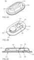
- Figs. 2A - 2C collectively illustrate a nonlimiting example of wearable device 102 as a wireless sensor device configured with one or more sensors to detect characteristics and/or qualities of subject 100. More particularly, Fig. 2A illustrates a wireless sensor device in accordance with one or more embodiments described herein, Fig. 2B illustrates an isometric view of the wireless sensor device of Fig. 2A with a top cover removed, in accordance with one or more embodiments described herein, and Fig. 2C illustrates a cross-section view of the wireless sensor device illustrated in Fig. 2A and components thereof illustrated in Fig. 2B , in accordance with one or more embodiments described herein.
- wearable device 102 may be disposable and/or reusable
- wearable device 102 may include a cover 202, one or more sensors (sensors 204 and 206 are illustrated), a battery 208, a base 210, a spacer 212, electronic circuitry 214, a transmitter or transceiver 216, a display 218, and a speaker 220.
- Electronic components within wearable device 102 such as some or all electronic components and related structure inside the device when cover 202 is in place, may be termed an "electronic assembly" elsewhere in this description.
- the electronic assembly may include a processing system and sensor data collection system, which are discussed below.
- the electronic assembly or parts thereof may be disposable and/or reusable relative to or with cover 202 and/or base 210.
- wearable device 102 may be attached to subject 100 via base 210 by, e.g., a skin-friendly adhesive or other device.
- Sensors 204, 206 may be in direct contact with subject 100 or separated from subject 100 by base 210 or other component(s) or device(s). Although two sensors are shown, wearable device 102 may have one sensor or more than two sensors.
- Spacer 212 may include a suitable insulating material to physically and/or electrically separate elements such as electronic circuitry 214 and sensor 206 or base 210, and additional insulating material may be employed instead of or together with spacer 212 for such a purpose.
- Such insulating material may include air, foam and/or Polyetheretherketone (PEEK) for insulation, for example.
- PEEK Polyetheretherketone
- sensors 204 and 206 are configured and placed to obtain data from subject 100.
- data is processed by wearable device 102, for example by a processor system-on-chip, to obtain data by any combination of analog, digital, and/or algorithmic processes.
- process may include “analysis” with respect to data; these terms thus may be used in combination, singly, interchangeably, or in the alternative as context dictates or permits.
- the obtained data may be stored in a memory on wearable device 102 or transmitted externally by transmitter/transceiver 216 as desired.
- the processor may execute instructions to process the data and obtain information regarding the subject, such as conditions related to the subject's health.
- the processed data or information may be displayed via display 218 of wearable device 102.
- data or “information” may be used in combination, singly, interchangeably, or in the alternative as context dictates or permits.
- the processed information may be provided to transmitter/transceiver 216 and, in turn, be transmitted externally to a user or device for any suitable purpose, such as information gathering, further processing, user or machine analysis, and/or storage.
- transmitter/transceiver 216 may transmit information such as physiological signals after analysis or in raw form to a remote device/server (e.g. a terrestrial or cloud-based server, or a mobile device such as a smartphone or tablet (not shown in FIG. 1 )).
- Information also may be provided in an audible form, such as a verbal report or nonverbal signal (e.g., alert).
- sensors can be utilized as or in addition to sensors 204 and 206 described above, including but not limited to temperature sensors; respiratory sensors; sensors of heart, brain, and other organ activity; body position accelerometers (e.g., tri-axial accelerometers, uni-axial accelerometers, bi-axial accelerometers, and/or gyroscopes); and/or pressure sensors.
- body position accelerometers e.g., tri-axial accelerometers, uni-axial accelerometers, bi-axial accelerometers, and/or gyroscopes
- pressure sensors e.g., pressure sensors.
- details of the electronic assembly, other electrical components, form factor, structural and electrical configuration, materials, etc. are illustrative and that various modifications of the same may be made in accordance with such factors as patient size, configuration, and comfort; physical environment; cost, etc..
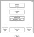
- Fig. 3 is a block diagram schematically illustrating basic elements that may comprise one or more embodiments of wearable device 102.
- wearable device 102 may include sensor 204, 206 to detect information, e.g., at least one physiological signal from subject 100; a processor 302 operably coupled to receive data collected from sensors 204, 206; and a memory 304 coupled to the processor, wherein memory 304 may store an application 306 including instructions that, when executed by the processor, cause the processor to perform operations related to the information detected by sensors 204, 206.
- Such operations may, for example, include processing and/or analyzing the collected data to determine a condition of subject 100 and/or derive information that, if provided to a user or other device, conveys information that can be used to determine a condition of subject 100.
- processor 302 may, for example, include processing and/or analyzing the collected data to determine a condition of subject 100 and/or derive information that, if provided to a user or other device, conveys information that can be used to determine a condition of subject 100.
- Operations related to detecting information by the sensors, collecting data from the information and providing the data to processor 302, executing application 306, and outputting the processed or related information via transmitter/transceiver 216, display 218, and/or speaker 220 are controlled by sequencing and scheduling schemes according to various clocks. Some such schemes rely heavily on processor 302 to control, collect, and process the sensor data which, while having some advantages, nevertheless may be prone to issues related to high power consumption such as reduced battery life, excessive heat generation, high sampling jitter, maximum achievable bandwidth, and unpredictable timing of events related to the sensor data collection and processing, to name a few.
- Fig. 4 shows a block diagram illustrating features of one such system.
- a system 400 may use a processor 402 to control, acquire, and process data from multiple sensors. These systems may schedule timing critical events related to sensor data collection and processing of the sensor data and data of peripherals such as a display 404a, a transmitter/transceiver 404b, or a speaker 404c via I/O interface(s) 404, for example using a combination of timers 406 and interrupts 408, 410.
- peripherals such as a display 404a, a transmitter/transceiver 404b, or a speaker 404c via I/O interface(s) 404, for example using a combination of timers 406 and interrupts 408, 410.
- sensor data may be analog data converted to digital data using an analog-to-digital converter (ADC) 412
- processed data output from processor 402 may be digital data output to one or more peripherals and/or converted to analog data via a digital-to-analog converter (DAC) 414.
- ADC analog-to-digital converter
- DAC digital-to-analog converter
- the output of DAC 414, via a driver 416, may provide the subject with a signal 418 to detect or permit measurement of a physiological sign or to stimulate a response, both of which may be sensed and input to ADC 412 as discussed above.
- signal 418 may cause light to be generated in a pulse oximeter, the output of which may be input to ADC 412.
- Timing related to critical events and priorities rely on accurate synchronization, and complex systems such as system 400 may have multiple such critical events and priorities, which may lead to uncertainty in timing of the events.
- critical events and priorities e.g., sensor selection, ADC triggering, buffering, data write/read, instruction processing, etc.
- Processor 402 and a memory 420 which may store application instructions for execution by processor 402, may be a significant part of the system in terms of transistors/gates. System 400 may thus run at a high system clock frequency and suffer significantly high dynamic and static power consumption.
- processor 402 is responsible for controlling and processing data of multiple sensors, the maximum bandwidth achievable for the system may be limited by high power consumption and few available processor cycles for data acquisition and processing.
- scheduling, sequencing, and data acquisition management may be decoupled from (i.e., not performed by) the processor.
- power to the processor and its operation can be managed synchronously with, e.g., data collection such that data may be collected and stored in the background during a low-power processor time.
- a clock setting a power supply to the processor can be shut down during (decoupled) data collection and, when a desired amount of data has been collected and/or stored, power is supplied to activate (e.g., "wake up") the processor to process the data and then shut down again when the processing is complete.
- a block diagram illustrating this and other features is shown schematically in Fig. 5 .
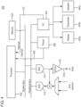
- Fig. 5 shows a block diagram of elements of a monitoring system in which certain functions may be decoupled from a processor, in accordance with one or more embodiments described herein.
- system 500 may be a System-on-Chip (SoC) capable of use with wirelessly connected sensory devices such as a wireless wearable device 102.
- SoC System-on-Chip
- system 500 may include a processor sub-system 502 and a sensor data collection system 503 comprising an analog front end (AFE) interface 504 and an analog front end (AFE) 506.
- AFE analog front end
- AFE analog front end
- processor sub-system 502 may include may include a processor 508, a shared system memory 510 (e.g., a static random access memory (SRAM) chip), a memory controller 512 (e.g., a direct memory access (DMA) controller), a system bus 514, and a peripheral bus 516.
- processor 508, system memory 510, and memory controller 512 are shown coupled to system bus 514.
- SoC SoC
- some of the foregoing components or other components may be provided on- or off-chip, although for convenience of description such components may be described herein as being components of system 500.
- AFE interface 504 includes a programmable event sequencer and scheduler (ESS) 518 coupled to system bus 514 via register controls 520 and peripheral bus 516, a timing generator 522, an optional hardware digital signal processor (DSP) 524, and a buffer 526.
- ESS programmable event sequencer and scheduler
- DSP hardware digital signal processor
- processor 508 may be a microprocessor that controls configuration and communication tasks.
- Processor 508 is shown decoupled from sensor scheduling, sequencing, and data acquisition, thereby allowing processor 508 to enter a low-power mode (e.g., "sleep"), through a SLEEP instruction or otherwise, while ESS 518 manages the sensor scheduling, sequencing, and data collection.
- a low-power mode e.g., "sleep”
- ESS 518 manages the sensor scheduling, sequencing, and data collection.
- one or more clocks to processor 508 may be turned off, excluding interface modules, for example. In some embodiments, these exclusions may be switched on independently of clock gating selection in order to keep processor 508 behaving normally to incoming requests.
- buffer 526 provides, according to the present invention, a wake signal to processor 508. Another determinant not part of the present invention, for waking processor 508 may be employed. Once awake, processor 508 or memory controller 512 can retrieve data from buffer 526 for processing.
- DSP 524 may be a microprocessor operating in either single processor mode or, with processor 508, in dual processor mode. DSP 524 may perform signal processing-intensive tasks when in dual processor mode, for example. When in single processor mode, DSP 524 may perform both control/communications and signal processing. DSP 524 is also capable of being set to a sleep mode.
- AFE 506 may include a selector 528 configured to receive analog sensor data and controllably output the analog data to an ADC 530 according to a sensor select signal 532 from ESS 518.
- ADC 530 may be configured to receive the selected analog data 534, convert analog data 534 to digital data 536, and output digital data 536 to buffer 526 (optionally via DSP 524) in accordance with a trigger signal 538 from ESS 518.
- processed data output from processor 508 may be digital data output to one or more peripherals via peripheral bus 516 and/or converted to analog data via a DAC 540 via ESS 518.
- the output of DAC 540 via a driver 542, may provide the subject with a signal 544 to detect or permit measurement of a physiological sign or to stimulate a response, both of which may be sensed and input to ADC 530 as discussed above.
- signal 544 may cause light to be generated in a pulse oximeter, the output of which may be input to ADC 530.
- the output of DAC 540 may be fed back to the output of selector 528 to improve the signal-to-noise ratio of the input to ADC 530.
- Sensory information may be output via suitable peripheral interfaces.
- SPI serial peripheral interface
- MEM microelectromechanical systems
- gyroscopes etc.
- UART interfaces also may be provided, one for Bluetooth Low Energy (BTLE) access and another debug access, by way of nonlimiting example.
- BTLE Bluetooth Low Energy
- I2C master interface may be provided for Altimeter access.
- system 500 may operate in two power domains - a "VDD" domain and a "VDD_SW' domain.
- the VDD domain may be an Always-ON domain whereas the VDD_SW may be switched to a low-power SLEEP-state to reduce dynamic and static power, for example.
- the VDD domain may include one or more of clock control, reset control, power-management, and the AFE interface.
- the processor subsystem, peripherals, and other components, one or more of which may be within the core block, may be in the VDD_SW domain.
- the sequencing of events from Normal Power mode (ON-mode) to Low Power mode (SLEEP-mode) may be managed by ESS 518.
- processor 508 may set up and synchronize timers and the wake-up. For example, processor 508 may enable a down-counting timer along with a master-timer, allowing the down-counting timer and master-timer to be in sync.
- SLEEP mode may be entered when the down-counting timer expires.
- Other determinants may be used to cause SLEEP mode, including but not limited to an interruption of sensor data collection or end of data retrieval from buffer 526.
- NORMAL power mode may resume in accordance with expiration of a sleep timer and/or a trigger.
- a sleep timer may begin to count down from a preloaded value and NORMAL mode may resume when the sleep timer expires.
- NORMAL mode may resume in response to a trigger, which may be an external interrupt as from a MEMS or BTLE device, from a buffer 526 Almost-Full flag or a battery-brownout signal. The countdown of the sleep timer may begin in accordance with the trigger.
- a clock to the core may be turned “OFF”.
- the clock to the core may be turned “ON”, and processor 508 may continue from where it was held.
- ESS 518 may be a time-driven sequencer to perform a sequence of "events.” Within each "event", multiple instructions and triggers can be scheduled, including but not limited to writing analog and digital control registers, triggering DAC 540 and ADC 530 at programmed times; passing a time stamp received from timing generator 522 at an identifiable trigger to buffer 526 to identify, e.g., when data is captured at selector 528 or an event happened; identifying ADC streams in accordance with the trigger to distinguish data by sensor; etc. ESS 518 also may enable one or more core components to be in low-power while it manages the AFE data capturing.
- ESS 518 can manage scheduling, sequencing, and data acquisition.
- Fig. 5 shows ESS 518 controlling sensor selection with sensor select signal 532, ADC output with trigger 538, and data write to buffer 528 with data_wr signal 546.
- ESS 518 itself may be operably coupled to timing generator 522, and ESS 518 and timing generator 522 may be coupled to system bus 514 via register controls 520.
- Timing generator 522 may act as a reference clock for timings provided by ESS 518 and, because ESS 518 can have a small instruction memory, ESS 518 may be programmable and maintain accurate timing in accordance with the reference clock provided by timing generator 522, while consuming less power than a system under single processor control such as system 400. In particular, the sum of power consumed by ESS 518 and processor 508 in performing their operations as part of wearable device 102 may be less than the power consumed by processor 402 in performing similar operations if part of wearable device 102.
- Fig. 6 illustrates an example of a system 600 that may implement monitoring in accordance with one or more embodiments described herein.
- System 600 may include a sensor data collection system 603, processor 608, system memory 610, DMA 612, system bus 614, and peripheral bus 616 corresponding structurally and/or functionally, at least in part, to sensor data collection system 503, processor 508, system memory 510, DMA 512, system bus 514, and peripheral bus 516, respectively, shown in Fig. 5 .
- System 600 may also include a display 604a, transmitter/transceiver 604b, speaker 604c, and/or other peripherals coupled to peripheral bus 616 via I/O interface(s) 604.
- Operations described herein may be implemented using any suitable controller or processor, and software application, which may be stored on any suitable storage location or computer-readable medium.
- the software application may provide instructions that enable processor 508 (608) and/or ESS 512 to perform one or more operations described herein.
- the disclosed processing may be performed by the wearable device or by an external device including but not limited to a sensor/relay/cloud processor, a smartphone device, and/or a cloud computing system.
- the electronic assembly or components thereof may include or comprise one or more of SoC hardware (SoC HW), an operating system, hardware layer abstraction, debug layers, test modules, and device drivers.
- SoC HW SoC hardware
- a nonlimiting example of a suitable SoC may include one or more of the following:
- ARC-610D 32-bit microprocessor as control processor (e.g., processor 508) may have one or more of the following (no limitation should be inferred):
- An example of an ARC-610D 32-bit microprocessor with XY Memory for DSP Processing may have one or more of the following (no limitation should be inferred):
- Embodiments described herein can take the form of an entirely hardware implementation, an entirely software implementation, or an implementation containing both hardware and software elements.
- Embodiments may be implemented in software, which includes, but is not limited to, application software, firmware, resident software, microcode, etc.
- Operations described herein may be implemented using any suitable controllers or processors, and software applications, which may be stored on any suitable storage location or computer-readable medium.
- the software application provides instructions that enable the processors or controllers to perform the operations described herein.
- embodiments may take the form of a computer program product accessible from a computer-usable or computer-readable medium providing program code for use by or in connection with a computer or any instruction execution system.
- a computer-usable or computer-readable medium can be any apparatus that can contain, store, communicate, propagate, or transport the program for use by or in connection with the instruction execution system, apparatus, or device.
- the medium may be an electronic, magnetic, optical, electromagnetic, infrared, semiconductor system (or apparatus or device), or a propagation medium.
- Examples of a computer-readable medium include a semiconductor or solid state memory, magnetic tape, a removable computer diskette, a random access memory (RAM), a read-only memory (ROM), a rigid magnetic disk, and an optical disk.
- Current examples of optical disks include DVD, compact disk-read-only memory (CD-ROM), and compact disk - read/write (CD-R/W).
Landscapes
- Health & Medical Sciences (AREA)
- Life Sciences & Earth Sciences (AREA)
- Engineering & Computer Science (AREA)
- Physics & Mathematics (AREA)
- Medical Informatics (AREA)
- Animal Behavior & Ethology (AREA)
- Biophysics (AREA)
- Pathology (AREA)
- Biomedical Technology (AREA)
- Heart & Thoracic Surgery (AREA)
- Veterinary Medicine (AREA)
- Molecular Biology (AREA)
- Surgery (AREA)
- Public Health (AREA)
- General Health & Medical Sciences (AREA)
- Physiology (AREA)
- Pulmonology (AREA)
- Theoretical Computer Science (AREA)
- Computer Networks & Wireless Communication (AREA)
- General Engineering & Computer Science (AREA)
- General Physics & Mathematics (AREA)
- Measuring And Recording Apparatus For Diagnosis (AREA)
- Power Sources (AREA)
Claims (10)
- Système de surveillance, comprenant :un bus de système (514, 614) ;un bus périphérique (516, 616) ;un système de collecte de données de capteur (503, 603) configuré pour commander la collecte de données de capteur associées à une ou plusieurs caractéristiques d'un sujet (100), le système de collecte de données de capteur (503, 603) comprenant :un séquenceur et ordonnanceur d'événements, ESS (518), couplé au bus de système (514, 614) via le bus périphérique (516, 616), l'ESS (518) étant configuré pour commander le séquencement et l'ordonnancement de la collecte de données de capteur, etun tampon (526) configuré pour recevoir et mettre en mémoire tampon des données correspondant aux données de capteur collectées à partir d'un ou de plusieurs capteurs (204, 206) conformément à un signal fourni par l'ESS (518) ; etun ou plusieurs processeurs (302, 402, 508, 608) configurés pour :recevoir les données mises en mémoire tampon du tampon (526) conformément à un signal de réveil ;traiter les données reçues ; etsortir les données traitées ;dans lequel le séquencement et la programmation de la collecte de données de capteur par le système de collecte de données de capteur (503, 603) sont découplés du ou des processeurs (302, 402, 508, 608) ;le ou les processeurs (302, 402, 508, 608) sont configurés pour entrer dans un mode veille à faible consommation d'énergie pendant la collecte de données de capteur par le système de collecte de données de capteur (503, 603), le mode veille à faible consommation empêchant le ou les processeurs (302, 402, 508, 608) de recevoir les données mises en mémoire tampon, pour traiter les données reçues et produire les données traitées ;le ou les processeurs (302, 402, 508, 608) étant configurés pour quitter le mode veille et reprendre la réception des données mises en mémoire tampon conformément au signal de réveil ; eten réponse à la saturation du tampon (526), le tampon (526) fournissant le signal de réveil au ou aux processeurs (302, 402, 508, 608).
- Système de surveillance selon la revendication 1, comprenant en outre :un convertisseur analogique-numérique, ADC (412, 530), configuré pour recevoir des données de capteur analogiques (534), convertir les données de capteur analogiques (534) en données de capteur numériques (536), et émettre les données de capteur numériques (536) en fonction d'un signal de déclenchement (538) ;les données reçues et mises en mémoire tampon par le tampon (526) comprenant les données de capteur numériques (536) émises par l'ADC (412, 530).
- Système de surveillance selon la revendication 2, comprenant en outre :
un émetteur (216, 404b) configuré pour recevoir et transmettre les données traitées 2mises par le ou les processeurs (302, 402, 508, 608). - Système de surveillance selon la revendication 3, comprenant en outre :le ou les capteurs (204, 206) configurés pour fournir les données de capteur (534) ; etune base (210) configurée pour supporter le ou les capteurs (204, 206), le système de collecte de données de capteur (503, 603) et le ou les processeurs (302, 402, 508, 608).
- Système de surveillance selon la revendication 4, comprenant en outre :un émetteur (216, 404b) configuré pour recevoir et transmettre les données traitées émises par le ou les processeurs (302, 402, 508, 608) ;la base (210) étant configurée pour supporter l'émetteur (216, 404b).
- Système de surveillance selon la revendication 4, comprenant en outre :une ou plusieurs batteries (208) configurées pour alimenter le système de collecte de données de capteur (503, 603) et le ou les processeurs (302, 402, 508, 608) ;la ou les batteries (208) étant supportées par la base (216, 404b).
- Système de surveillance selon la revendication 1, dans lequel le signal de réveil est fourni au ou aux processeurs (302, 402, 508, 608) conformément à une interruption externe.
- Système de surveillance selon la revendication 1, dans lequel le signal de réveil est fourni au ou aux processeurs (302, 402, 508, 608) conformément à l'expiration d'un temporisateur.
- Système de surveillance selon la revendication 4, dans lequel le ou les capteurs (204, 206) comprennent un capteur ECG et un capteur respiratoire.
- Dispositif portable, comprenant:une base (210) ; etun système de surveillance selon l'une quelconque des revendications 1 à 9 supporté par la base (210).
Applications Claiming Priority (2)
| Application Number | Priority Date | Filing Date | Title |
|---|---|---|---|
| US16/121,772 US11172882B2 (en) | 2018-09-05 | 2018-09-05 | Monitoring system |
| PCT/US2019/049439 WO2020051177A1 (fr) | 2018-09-05 | 2019-09-04 | Système de surveillance |
Publications (3)
| Publication Number | Publication Date |
|---|---|
| EP3847524A1 EP3847524A1 (fr) | 2021-07-14 |
| EP3847524A4 EP3847524A4 (fr) | 2022-05-25 |
| EP3847524B1 true EP3847524B1 (fr) | 2025-03-05 |
Family
ID=69640822
Family Applications (1)
| Application Number | Title | Priority Date | Filing Date |
|---|---|---|---|
| EP19857504.5A Active EP3847524B1 (fr) | 2018-09-05 | 2019-09-04 | Système de surveillance |
Country Status (5)
| Country | Link |
|---|---|
| US (1) | US11172882B2 (fr) |
| EP (1) | EP3847524B1 (fr) |
| JP (1) | JP7089312B2 (fr) |
| CN (1) | CN112585561B (fr) |
| WO (1) | WO2020051177A1 (fr) |
Families Citing this family (18)
| Publication number | Priority date | Publication date | Assignee | Title |
|---|---|---|---|---|
| CA2797980C (fr) | 2010-05-12 | 2015-08-18 | Irhythm Technologies, Inc. | Caracteristiques de dispositif et elements de construction pour adherence a long terme |
| JP6198849B2 (ja) | 2013-01-24 | 2017-09-20 | アイリズム・テクノロジーズ・インコーポレイテッドiRhythm Technologies,Inc. | 生理学的信号をモニターする電子装置、及び該電子装置の部分を除去交換する方法 |
| US20160120434A1 (en) | 2014-10-31 | 2016-05-05 | Irhythm Technologies, Inc. | Wireless physiological monitoring device and systems |
| AU2016315947B2 (en) | 2015-08-31 | 2021-02-18 | Masimo Corporation | Wireless patient monitoring systems and methods |
| US11076777B2 (en) | 2016-10-13 | 2021-08-03 | Masimo Corporation | Systems and methods for monitoring orientation to reduce pressure ulcer formation |
| JP7406001B2 (ja) | 2020-02-12 | 2023-12-26 | アイリズム・テクノロジーズ・インコーポレイテッド | 患者の生理学的特徴を推論するための、非侵襲的な心臓モニタ、および記録された心臓データの使用方法 |
| JP7737391B2 (ja) | 2020-03-20 | 2025-09-10 | マシモ・コーポレイション | 非侵襲的な体温測定のためのウェアラブルデバイス |
| USD974193S1 (en) | 2020-07-27 | 2023-01-03 | Masimo Corporation | Wearable temperature measurement device |
| USD980091S1 (en) | 2020-07-27 | 2023-03-07 | Masimo Corporation | Wearable temperature measurement device |
| WO2022032117A1 (fr) | 2020-08-06 | 2022-02-10 | Irhythm Technologies, Inc. | Dispositif adhésif de surveillance physiologique |
| JP7796108B2 (ja) | 2020-08-06 | 2026-01-08 | アイリズム・テクノロジーズ・インコーポレイテッド | 生理学的モニタリング装置の電気部品 |
| USD1072837S1 (en) | 2020-10-27 | 2025-04-29 | Masimo Corporation | Display screen or portion thereof with graphical user interface |
| KR102517472B1 (ko) * | 2021-03-12 | 2023-04-04 | 주식회사 휴이노 | 생체 신호 데이터를 추출하기 위한 방법, 디바이스 및 비일시성의 컴퓨터 판독 가능 기록 매체 |
| USD1063079S1 (en) | 2021-08-06 | 2025-02-18 | Irhythm Technologies, Inc. | Physiological monitoring device |
| USD1000975S1 (en) | 2021-09-22 | 2023-10-10 | Masimo Corporation | Wearable temperature measurement device |
| US12521021B2 (en) | 2021-09-22 | 2026-01-13 | Masimo Corporation | Wearable device for noninvasive body temperature measurement |
| USD1048908S1 (en) | 2022-10-04 | 2024-10-29 | Masimo Corporation | Wearable sensor |
| KR102819401B1 (ko) * | 2022-11-03 | 2025-06-13 | 인제대학교 산학협력단 | 심부 체온 측정이 가능한 비위관 |
Family Cites Families (6)
| Publication number | Priority date | Publication date | Assignee | Title |
|---|---|---|---|---|
| TWI424832B (zh) * | 2008-12-15 | 2014-02-01 | 波提亞斯數位康健公司 | 與身體有關的接收器及其方法 |
| JP5470556B2 (ja) * | 2010-07-16 | 2014-04-16 | 伊原電子工業株式会社 | 生体信号検出装置、その制御方法及びプログラム |
| US9665155B2 (en) * | 2013-12-28 | 2017-05-30 | Intel Corporation | Techniques for increasing energy efficiency of sensor controllers that receive data from one or more sensors |
| US9619377B2 (en) * | 2014-05-29 | 2017-04-11 | Apple Inc. | System on a chip with always-on processor which reconfigures SOC and supports memory-only communication mode |
| US20180329713A1 (en) | 2014-12-10 | 2018-11-15 | Intel Corporation | Fitness sensor with low power attributes in sensor hub |
| US10194264B2 (en) | 2015-09-22 | 2019-01-29 | Veniam, Inc. | Systems and methods for collecting sensor data in a network of moving things |
-
2018
- 2018-09-05 US US16/121,772 patent/US11172882B2/en active Active
-
2019
- 2019-09-04 EP EP19857504.5A patent/EP3847524B1/fr active Active
- 2019-09-04 CN CN201980054791.7A patent/CN112585561B/zh active Active
- 2019-09-04 WO PCT/US2019/049439 patent/WO2020051177A1/fr not_active Ceased
- 2019-09-04 JP JP2021504451A patent/JP7089312B2/ja active Active
Also Published As
| Publication number | Publication date |
|---|---|
| WO2020051177A1 (fr) | 2020-03-12 |
| JP2021534844A (ja) | 2021-12-16 |
| US11172882B2 (en) | 2021-11-16 |
| CN112585561B (zh) | 2025-01-10 |
| JP7089312B2 (ja) | 2022-06-22 |
| EP3847524A4 (fr) | 2022-05-25 |
| CN112585561A (zh) | 2021-03-30 |
| US20200069252A1 (en) | 2020-03-05 |
| EP3847524A1 (fr) | 2021-07-14 |
Similar Documents
| Publication | Publication Date | Title |
|---|---|---|
| EP3847524B1 (fr) | Système de surveillance | |
| US10959626B2 (en) | Self-powered wearable for continuous biometrics monitoring | |
| CN110192383B (zh) | 电子设备及其操作方法 | |
| US9510790B2 (en) | Method for measuring biological signal and wearable electronic device for the same | |
| US8904214B2 (en) | System and method for conserving power in a medical device | |
| CN103218906B (zh) | 跌倒数据采集分析平台 | |
| US20180097538A1 (en) | Ultra low power sensing platform with multimodal radios | |
| CN106175664A (zh) | 监测生物信号的可穿戴装置和方法 | |
| CN103239216A (zh) | 一种体能监测装置及体能监测方法 | |
| Dell’Agnola et al. | MBioTracker: Multimodal self-aware bio-monitoring wearable system for online workload detection | |
| TW201527951A (zh) | 用於增加感測器控制器之能源效率的技術 | |
| Ma et al. | Smart-clothes—Prototyping of a health monitoring platform | |
| CN113365550A (zh) | 用于基于rem睡眠阶段计算恢复指数的方法及其电子设备 | |
| CN107643787A (zh) | 可穿戴计算机 | |
| US10022051B2 (en) | Information provision system, electronic device, method and storage medium | |
| CN110638462A (zh) | 一种带步态分析的穿戴式足底生理信息采集系统 | |
| US20170315821A1 (en) | Activating an electronic device | |
| CN211022594U (zh) | 一种可穿戴式帕金森震颤监测手环装置 | |
| CN109316181A (zh) | 心电信号采集设备控制方法、装置、设备和存储介质 | |
| CN206648684U (zh) | 智能睡眠质量检测系统 | |
| EP3946024A1 (fr) | Appareil et procédé de mesure de contact peau à peau entre un nouveau-né et un parent | |
| Roggen | ARM cortex M4-based extensible multimodal wearable platform for sensor research and context sensing from motion & sound | |
| MingRui et al. | Design of Health Monitoring System Based on STM32 | |
| JP2017127371A (ja) | ライフロガー | |
| CN106662897B (zh) | 用于动态资源管理的分散体系架构 |
Legal Events
| Date | Code | Title | Description |
|---|---|---|---|
| STAA | Information on the status of an ep patent application or granted ep patent |
Free format text: STATUS: THE INTERNATIONAL PUBLICATION HAS BEEN MADE |
|
| PUAI | Public reference made under article 153(3) epc to a published international application that has entered the european phase |
Free format text: ORIGINAL CODE: 0009012 |
|
| STAA | Information on the status of an ep patent application or granted ep patent |
Free format text: STATUS: REQUEST FOR EXAMINATION WAS MADE |
|
| 17P | Request for examination filed |
Effective date: 20210120 |
|
| AK | Designated contracting states |
Kind code of ref document: A1 Designated state(s): AL AT BE BG CH CY CZ DE DK EE ES FI FR GB GR HR HU IE IS IT LI LT LU LV MC MK MT NL NO PL PT RO RS SE SI SK SM TR |
|
| DAV | Request for validation of the european patent (deleted) | ||
| DAX | Request for extension of the european patent (deleted) | ||
| A4 | Supplementary search report drawn up and despatched |
Effective date: 20220426 |
|
| RIC1 | Information provided on ipc code assigned before grant |
Ipc: G06F 1/32 20190101AFI20220420BHEP |
|
| GRAP | Despatch of communication of intention to grant a patent |
Free format text: ORIGINAL CODE: EPIDOSNIGR1 |
|
| STAA | Information on the status of an ep patent application or granted ep patent |
Free format text: STATUS: GRANT OF PATENT IS INTENDED |
|
| INTG | Intention to grant announced |
Effective date: 20241008 |
|
| GRAS | Grant fee paid |
Free format text: ORIGINAL CODE: EPIDOSNIGR3 |
|
| GRAA | (expected) grant |
Free format text: ORIGINAL CODE: 0009210 |
|
| STAA | Information on the status of an ep patent application or granted ep patent |
Free format text: STATUS: THE PATENT HAS BEEN GRANTED |
|
| P01 | Opt-out of the competence of the unified patent court (upc) registered |
Free format text: CASE NUMBER: APP_2151/2025 Effective date: 20250113 |
|
| AK | Designated contracting states |
Kind code of ref document: B1 Designated state(s): AL AT BE BG CH CY CZ DE DK EE ES FI FR GB GR HR HU IE IS IT LI LT LU LV MC MK MT NL NO PL PT RO RS SE SI SK SM TR |
|
| REG | Reference to a national code |
Ref country code: GB Ref legal event code: FG4D |
|
| REG | Reference to a national code |
Ref country code: CH Ref legal event code: EP |
|
| REG | Reference to a national code |
Ref country code: DE Ref legal event code: R096 Ref document number: 602019067007 Country of ref document: DE |
|
| REG | Reference to a national code |
Ref country code: IE Ref legal event code: FG4D |
|
| PG25 | Lapsed in a contracting state [announced via postgrant information from national office to epo] |
Ref country code: RS Free format text: LAPSE BECAUSE OF FAILURE TO SUBMIT A TRANSLATION OF THE DESCRIPTION OR TO PAY THE FEE WITHIN THE PRESCRIBED TIME-LIMIT Effective date: 20250605 |
|
| PG25 | Lapsed in a contracting state [announced via postgrant information from national office to epo] |
Ref country code: FI Free format text: LAPSE BECAUSE OF FAILURE TO SUBMIT A TRANSLATION OF THE DESCRIPTION OR TO PAY THE FEE WITHIN THE PRESCRIBED TIME-LIMIT Effective date: 20250305 |
|
| REG | Reference to a national code |
Ref country code: NL Ref legal event code: MP Effective date: 20250305 |
|
| PG25 | Lapsed in a contracting state [announced via postgrant information from national office to epo] |
Ref country code: ES Free format text: LAPSE BECAUSE OF FAILURE TO SUBMIT A TRANSLATION OF THE DESCRIPTION OR TO PAY THE FEE WITHIN THE PRESCRIBED TIME-LIMIT Effective date: 20250305 |
|
| REG | Reference to a national code |
Ref country code: LT Ref legal event code: MG9D |
|
| PG25 | Lapsed in a contracting state [announced via postgrant information from national office to epo] |
Ref country code: NO Free format text: LAPSE BECAUSE OF FAILURE TO SUBMIT A TRANSLATION OF THE DESCRIPTION OR TO PAY THE FEE WITHIN THE PRESCRIBED TIME-LIMIT Effective date: 20250605 |
|
| PG25 | Lapsed in a contracting state [announced via postgrant information from national office to epo] |
Ref country code: HR Free format text: LAPSE BECAUSE OF FAILURE TO SUBMIT A TRANSLATION OF THE DESCRIPTION OR TO PAY THE FEE WITHIN THE PRESCRIBED TIME-LIMIT Effective date: 20250305 |
|
| PG25 | Lapsed in a contracting state [announced via postgrant information from national office to epo] |
Ref country code: LV Free format text: LAPSE BECAUSE OF FAILURE TO SUBMIT A TRANSLATION OF THE DESCRIPTION OR TO PAY THE FEE WITHIN THE PRESCRIBED TIME-LIMIT Effective date: 20250305 |
|
| PG25 | Lapsed in a contracting state [announced via postgrant information from national office to epo] |
Ref country code: GR Free format text: LAPSE BECAUSE OF FAILURE TO SUBMIT A TRANSLATION OF THE DESCRIPTION OR TO PAY THE FEE WITHIN THE PRESCRIBED TIME-LIMIT Effective date: 20250606 Ref country code: BG Free format text: LAPSE BECAUSE OF FAILURE TO SUBMIT A TRANSLATION OF THE DESCRIPTION OR TO PAY THE FEE WITHIN THE PRESCRIBED TIME-LIMIT Effective date: 20250305 |
|
| REG | Reference to a national code |
Ref country code: AT Ref legal event code: MK05 Ref document number: 1773495 Country of ref document: AT Kind code of ref document: T Effective date: 20250305 |
|
| PG25 | Lapsed in a contracting state [announced via postgrant information from national office to epo] |
Ref country code: NL Free format text: LAPSE BECAUSE OF FAILURE TO SUBMIT A TRANSLATION OF THE DESCRIPTION OR TO PAY THE FEE WITHIN THE PRESCRIBED TIME-LIMIT Effective date: 20250305 |
|
| PG25 | Lapsed in a contracting state [announced via postgrant information from national office to epo] |
Ref country code: SE Free format text: LAPSE BECAUSE OF FAILURE TO SUBMIT A TRANSLATION OF THE DESCRIPTION OR TO PAY THE FEE WITHIN THE PRESCRIBED TIME-LIMIT Effective date: 20250305 |
|
| PG25 | Lapsed in a contracting state [announced via postgrant information from national office to epo] |
Ref country code: SM Free format text: LAPSE BECAUSE OF FAILURE TO SUBMIT A TRANSLATION OF THE DESCRIPTION OR TO PAY THE FEE WITHIN THE PRESCRIBED TIME-LIMIT Effective date: 20250305 |
|
| PG25 | Lapsed in a contracting state [announced via postgrant information from national office to epo] |
Ref country code: PT Free format text: LAPSE BECAUSE OF FAILURE TO SUBMIT A TRANSLATION OF THE DESCRIPTION OR TO PAY THE FEE WITHIN THE PRESCRIBED TIME-LIMIT Effective date: 20250707 |
|
| PGFP | Annual fee paid to national office [announced via postgrant information from national office to epo] |
Ref country code: DE Payment date: 20250917 Year of fee payment: 7 |
|
| PG25 | Lapsed in a contracting state [announced via postgrant information from national office to epo] |
Ref country code: PL Free format text: LAPSE BECAUSE OF FAILURE TO SUBMIT A TRANSLATION OF THE DESCRIPTION OR TO PAY THE FEE WITHIN THE PRESCRIBED TIME-LIMIT Effective date: 20250305 Ref country code: IT Free format text: LAPSE BECAUSE OF FAILURE TO SUBMIT A TRANSLATION OF THE DESCRIPTION OR TO PAY THE FEE WITHIN THE PRESCRIBED TIME-LIMIT Effective date: 20250305 |
|
| PGFP | Annual fee paid to national office [announced via postgrant information from national office to epo] |
Ref country code: GB Payment date: 20250924 Year of fee payment: 7 |
|
| PG25 | Lapsed in a contracting state [announced via postgrant information from national office to epo] |
Ref country code: AT Free format text: LAPSE BECAUSE OF FAILURE TO SUBMIT A TRANSLATION OF THE DESCRIPTION OR TO PAY THE FEE WITHIN THE PRESCRIBED TIME-LIMIT Effective date: 20250305 |
|
| PGFP | Annual fee paid to national office [announced via postgrant information from national office to epo] |
Ref country code: FR Payment date: 20250925 Year of fee payment: 7 |
|
| PG25 | Lapsed in a contracting state [announced via postgrant information from national office to epo] |
Ref country code: CZ Free format text: LAPSE BECAUSE OF FAILURE TO SUBMIT A TRANSLATION OF THE DESCRIPTION OR TO PAY THE FEE WITHIN THE PRESCRIBED TIME-LIMIT Effective date: 20250305 Ref country code: EE Free format text: LAPSE BECAUSE OF FAILURE TO SUBMIT A TRANSLATION OF THE DESCRIPTION OR TO PAY THE FEE WITHIN THE PRESCRIBED TIME-LIMIT Effective date: 20250305 |
|
| PG25 | Lapsed in a contracting state [announced via postgrant information from national office to epo] |
Ref country code: RO Free format text: LAPSE BECAUSE OF FAILURE TO SUBMIT A TRANSLATION OF THE DESCRIPTION OR TO PAY THE FEE WITHIN THE PRESCRIBED TIME-LIMIT Effective date: 20250305 |
|
| PG25 | Lapsed in a contracting state [announced via postgrant information from national office to epo] |
Ref country code: SK Free format text: LAPSE BECAUSE OF FAILURE TO SUBMIT A TRANSLATION OF THE DESCRIPTION OR TO PAY THE FEE WITHIN THE PRESCRIBED TIME-LIMIT Effective date: 20250305 |
|
| PG25 | Lapsed in a contracting state [announced via postgrant information from national office to epo] |
Ref country code: IS Free format text: LAPSE BECAUSE OF FAILURE TO SUBMIT A TRANSLATION OF THE DESCRIPTION OR TO PAY THE FEE WITHIN THE PRESCRIBED TIME-LIMIT Effective date: 20250705 |
|
| REG | Reference to a national code |
Ref country code: DE Ref legal event code: R097 Ref document number: 602019067007 Country of ref document: DE |
|
| PLBE | No opposition filed within time limit |
Free format text: ORIGINAL CODE: 0009261 |
|
| STAA | Information on the status of an ep patent application or granted ep patent |
Free format text: STATUS: NO OPPOSITION FILED WITHIN TIME LIMIT |
|
| PG25 | Lapsed in a contracting state [announced via postgrant information from national office to epo] |
Ref country code: DK Free format text: LAPSE BECAUSE OF FAILURE TO SUBMIT A TRANSLATION OF THE DESCRIPTION OR TO PAY THE FEE WITHIN THE PRESCRIBED TIME-LIMIT Effective date: 20250305 |
|
| REG | Reference to a national code |
Ref country code: CH Ref legal event code: L10 Free format text: ST27 STATUS EVENT CODE: U-0-0-L10-L00 (AS PROVIDED BY THE NATIONAL OFFICE) Effective date: 20260114 |
|
| 26N | No opposition filed |
Effective date: 20251208 |
|
| REG | Reference to a national code |
Ref country code: CH Ref legal event code: H13 Free format text: ST27 STATUS EVENT CODE: U-0-0-H10-H13 (AS PROVIDED BY THE NATIONAL OFFICE) Effective date: 20260425 |