EP3847532B1 - Ausziehbarer mechanismus und steuerung mit ausziehbarem mechanismus - Google Patents
Ausziehbarer mechanismus und steuerung mit ausziehbarem mechanismus Download PDFInfo
- Publication number
- EP3847532B1 EP3847532B1 EP18932788.5A EP18932788A EP3847532B1 EP 3847532 B1 EP3847532 B1 EP 3847532B1 EP 18932788 A EP18932788 A EP 18932788A EP 3847532 B1 EP3847532 B1 EP 3847532B1
- Authority
- EP
- European Patent Office
- Prior art keywords
- extension
- link
- guide element
- controller
- various embodiments
- Prior art date
- Legal status (The legal status is an assumption and is not a legal conclusion. Google has not performed a legal analysis and makes no representation as to the accuracy of the status listed.)
- Active
Links
Images




Classifications
-
- A—HUMAN NECESSITIES
- A63—SPORTS; GAMES; AMUSEMENTS
- A63F—CARD, BOARD, OR ROULETTE GAMES; INDOOR GAMES USING SMALL MOVING PLAYING BODIES; VIDEO GAMES; GAMES NOT OTHERWISE PROVIDED FOR
- A63F13/00—Video games, i.e. games using an electronically generated display having two or more dimensions
- A63F13/20—Input arrangements for video game devices
- A63F13/24—Constructional details thereof, e.g. game controllers with detachable joystick handles
-
- A—HUMAN NECESSITIES
- A63—SPORTS; GAMES; AMUSEMENTS
- A63F—CARD, BOARD, OR ROULETTE GAMES; INDOOR GAMES USING SMALL MOVING PLAYING BODIES; VIDEO GAMES; GAMES NOT OTHERWISE PROVIDED FOR
- A63F13/00—Video games, i.e. games using an electronically generated display having two or more dimensions
- A63F13/90—Constructional details or arrangements of video game devices not provided for in groups A63F13/20 or A63F13/25, e.g. housing, wiring, connections or cabinets
- A63F13/92—Video game devices specially adapted to be hand-held while playing
-
- G—PHYSICS
- G06—COMPUTING OR CALCULATING; COUNTING
- G06F—ELECTRIC DIGITAL DATA PROCESSING
- G06F1/00—Details not covered by groups G06F3/00 - G06F13/00 and G06F21/00
- G06F1/16—Constructional details or arrangements
- G06F1/1613—Constructional details or arrangements for portable computers
- G06F1/1632—External expansion units, e.g. docking stations
Definitions
- Various embodiments generally relate to an extendable mechanism for a body structure, an extendable mechanism between a first part of a body structure and a second part of a body structure, and a controller with an extendable mechanism.
- various embodiments generally relate to an extendable mechanism for a game controller and a game controller with an extendable mechanism.
- game controllers for mobile phones typically include a clamping mechanism for attaching the mobile phone to the respective game controller.
- the clamping mechanism uses a single stack slider with continuous spring loading such that a retraction force is always acting to close the clamping mechanism as long as the clamping mechanism is being pulled apart.
- the retraction force would be acting to close the clamping mechanism.
- the clamping mechanism already has a strong retraction force to close the clamping mechanism which may cause harm to a user if the user accidentally releases the clamping mechanism while opening. This can result in the clamping mechanism of the game controller pinching the hands of the user from the strong retraction force of the clamping mechanism.
- some conventional game controllers use a single slider mechanism which are configured in a manner such that the slider mechanism is an add-on part that always results in a very wobbly and unstable sliding experience for the user. Such game controllers might cause irritation to the user and such game controller may also not be aesthetically pleasing.
- some conventional game controllers may include a clip foldable to the body of the controller.
- Such foldable clip typically takes up a lot of the space of the controller and usually sacrifices the ergonomic placement of buttons in order to fit the foldable clip.
- Various embodiments generally relate to an extendable mechanism for a body structure, an extendable mechanism between a first part of a body structure and a second part of a body structure, and a controller with an extendable mechanism.
- the controller may be a game controller for a mobile phone or a personal electronic device.
- the body structure in the various embodiments may be a body of the game controller.
- the extendable mechanism may be configured to be extended from the body of the game controller so as to receive or retain or hold the mobile phone or the personal electronic devices therebetween such that the mobile phone or personal electronic devices may be removably attached or secured or coupled to the body of the game controller. While the body structure is illustrated as a body of a game controller, it is understood that the body structure may be a body of any suitable device that require an extension.
- FIG. 1A shows a schematic diagram of an extendable mechanism 102 in a retracted state according to various embodiments.
- FIG. 1B shows a schematic diagram of the extendable mechanism 102 of FIG. 1A in an extended state according to various embodiments.
- the extendable mechanism 102 may be for a body structure 104.
- the extendable mechanism 102 may be for being mounted or secured or attached or coupled to the body structure 104.
- the extendable mechanism 102 may serve to provide an extension to the body structure 104.
- an outline of the body structure 104 is illustrated by a dotted-line.
- the body structure 104 may be of any shape or size or configuration depending on what is the device embodied by the body structure 104.
- the body structure 104 as shown in FIG. 1A and FIG. 1B is provided by way of example only and not limitation.
- the body structure 104 may be a body of a game controller for a mobile phone or a personal electronic device.
- the extendable mechanism 102 for the body structure 104 may include an extension member 110 according to various embodiments.
- the extension member 110 may be shaped or dimensioned or configured such that it may be for being concealed or contained or kept or held within the body structure 104 in the retracted state of the extendable mechanism 102, and may be for being extended or drawn out from the body structure 104 in the extended state of the extendable mechanism 102.
- the extension member 110 may serve to be a part of the extendable mechanism 102 that may be physically extended from the body structure 104.
- the extendable member 110 may be of an elongate shape.
- the extendable member 110 may be an elongate plate or an elongate panel. Accordingly, the extendable member 110 may be extendable in a lengthwise direction relative to the body structure 104 along a longitudinal axis 112 of the extendable member 110.
- the extendable mechanism 102 may further include a link member 120 which may be provided with an extension-member-guide element 122.
- the extension-member-guide element 122 may be configured for guiding a relative movement of the extension member 110 with respect to the body structure 104.
- the extension-member-guide element 122 may be configured for guiding the movement of the extension member 110 as the extension member 110 is being extended or drawn out from the body structure 104.
- the extension member 110 may be in engagement with the extension-member-guide element 122 of the link member 120 in a manner so as to be retractably extendable from the link member 120 (or retractably movable relative to the link member 120) in an extension direction 111 along an axis of the extension member 110.
- the extension-member-guide element 122 may guide a relative movement between the extension member 110 and the link member 120 of the extendable mechanism 102 such that the extension member 110 may be extendable relative to the link member 120 (or the extension member 110 may be extended or drawn out from the link member 120).
- the extension direction 111 of the extension member 110 may be along the longitudinal axis 112 of the elongate extension member 110.
- the extension-member-guide element 122 of the link member 120 may be a separate part from a link body 124 of the link member 120.
- extension-member-guide element 122 and the link body 124 may be two separate parts fixedly coupled or joined or connected or attached to each other so as to form the link member 120. According to various other embodiments, the extension-member-guide element 122 and the link body 124 may also be integrally molded or formed as a single unitary piece to form the link member 120.
- the extendable mechanism 102 may further include a link-member-guide element 130.
- the link-member-guide element 130 may be for being disposed at the body structure 104. Accordingly, the link-member-guide element 130 may be a separate part from the body structure 104, whereby the link-member-guide element 130 may be for being attached or coupled or fixed or joined or connected to the body structure 104, or an integral portion of the body structure 104, whereby the link-member-guide element 130 may be integrally molded or formed with the body structure 104 as a single unitary piece. According to various embodiments, the link-member-guide element 130 may be configured for guiding a relative movement of the link member 120 with respect to the body structure 104.
- the link member 120 may be in engagement with the link-member-guide element 130 in a manner so as to be retractably extendable from the link-member-guide element 130 (or retractably movable relative to the link-member-guide element 130) in the extension direction 111 of the extension member 110.
- the link-member-guide element 130 may guide a relative movement between the link member 120 and the link-member-guide element 130 such that the link member 120 may be extendable relative to the link-member-guide element 130 (or the link member 120 may be extended or drawn out from the link-member-guide element 130).
- the relative movement between the link member 120 and the link-member-guide element 130 may be parallel to the relative movement between the extension member 110 and the link member 120.
- the extension member 110 of the extendable mechanism 102 may serve as a main extension from the body structure 104, and the link member 120 may serve as a secondary extension from the body structure 104.
- the extension member 110 and the link member 120 may be arranged in an overlapping or a stacked configuration such that, when the extendable mechanism 102 is in the retracted state, the link member 120 may extend over and cover the extension member 110.
- the extendable mechanism 102 may provide a compact mechanism with dual-stage extensions for the body structure 104 such that the extendable mechanism 102 may only occupy a small area in the body structure 104.
- the extendable mechanism 102 may further include a biasing member 140.
- the biasing member 140 may be for being arranged between the link member 120 and the body structure 104.
- the biasing member 140 may serve to apply a biasing force on the link member 120 in a direction opposite to the extension direction 111 of the extension member 110.
- the biasing member 140 may serve to provide a retraction force, which may be against the extension movement of the link member 120, for retracting the link member 120 towards the body structure 104.
- the biasing member 140 may include a tape spring, a clock spring, a coil spring, a torsion spring, a compression spring, a tension spring, or any combination thereof.
- the extension member 110 may include a stopper element 114 at an end (or an inner end) of the extension member 110 opposite the extension direction 111 of the extension member 110.
- the stopper element 114 may include a protrusion projecting at least substantially perpendicular to the extension member 110 so as to provide a physical barrier or limit between the extension member 110 and the extension-member-guide element 122 of the link member 120 for preventing the entire extension member 110 from being pulled out of the extension-member-guide element 122 of the link member 120.
- the stopper element 114 may fix or set a maximum relative extension between the extension member 110 and the extension-member-guide element 122 of the link member 120.
- any further force applied to the extension member 110 in the extension direction 111 may cause the force to be transferred to the link member 120 for extending or drawing out the link member 120 relative to the link-member-guide element 130.
- the extension member 110 may be extended or drawn out first before the link member 120 may be extended or drawn out from the link-member-guide element 130.
- the link-member-guide element 130 is fixed to the body structure 104.
- the extension member 110 may include a protruding lip 316 (e.g. see FIG. 3 ) at another end (or an outer end) of the extension member 110 in the extension direction 111 of the extension member 110.
- the protruding lip and the stopper element 114 are disposed at opposite ends of the extension member 110.
- the protruding lip 316 may be at least substantially perpendicular to the extension member 110.
- the protruding lip 316 may serve to contact an edge of an object, such as the mobile phone or the personal electronic device, being placed between the protruding lip 316 of the extension member 110 of the extendable mechanism 102 and the body structure 104 such that the object may be removably attached or secured or coupled between the protruding lip 316 of the extendable mechanism 102 and the body structure 104.
- the protruding lip 316 and an extension body 115 of the extension member 110 may be separate parts. Accordingly, the protruding lip 316 may be joined or coupled or fixed or connected or attached to the extension body 115 of the extension member 110.
- the protruding lip 316 may be integrally molded or formed with the extension body 115 as a single unitary piece to form the extension member 110.
- the extendable mechanism 102 may be free of biasing member between the extension member 110 and the link member 120. Accordingly, the extendable mechanism 102 may be free of a biasing force being applied to retract the extension member 110 relative to the link member 120. Hence, a user may easily extend or draw out the extension member 110 from the link member 120 without risk of having any of the user's fingers being clamped. Subsequently, with the extension member 110 fully extended or drawn out, the user may then apply a force to the extension member 110 so as to overcome the biasing force applied on the link member 120 in order to extend or draw out the link member 120 with respect to the link-member-guide element 130 for further extending the extendable mechanism 102 such that an object (e.g.
- the mobile phone or personal electronic device may be placed between the protruding lip 316 of the extension member 110 of the extendable mechanism 102 and the body structure 104. Accordingly, the object may be retained between the protruding lip 316 of the extension member 110 of the extendable mechanism 102 and the body structure 104 by the biasing force acting on the link member 120.
- the extension member 110 and the extension-member-guide element 122 of the link member 120 may be engaged in a tongue and groove sliding engagement.
- the extension member 110 may include a pair of tongue projections along opposite side edges of the extension member 110 parallel to the axis or the extension direction 111 of the extension member 110
- the extension-member-guide element 122 of the link member 120 may include a pair of grooves facing towards each other and parallel to the axis or the extension direction 111 of the extension member 110.
- the pair of tongue projections of the extension member 110 and the pair of grooves of the extension-member-guide element 122 of the link member 120 may be configured to engage such that the respective tongue projections are slidable relative to the corresponding groove.
- the extension member 110 may include a pair of grooves along opposite side edges of the extension member 110 parallel to the axis or the extension direction 111 of the extension member 110, and the extension-member-guide element 122 of the link member 120 may include a pair of tongue projections directed towards each other and parallel to the axis or the extension direction 111 of the extension member 110. Accordingly, the pair of grooves of the extension member 110 and the pair of tongue projections of the extension-member-guide element 122 of the link member 120 may be configured to engage such that the respective tongue projections are slidable relative to the corresponding groove.
- the tongue and groove sliding engagement may include a protrusion and groove sliding arrangement, or a dovetail tongue and groove sliding arrangement, or a T-shaped tongue and groove sliding arrangement, or a J-shaped tongue and groove sliding arrangement, or an L-shaped tongue and groove sliding arrangement, or a hooked-like tongue and groove sliding arrangement, or any other suitable sliding arrangement.
- the link member 120 and the link-member-guide element 130 may be engaged in a tongue and groove sliding engagement.
- the link member 120 may include a pair of tongue projections extending along opposite side edges of the link member 120 parallel to the axis or the extension direction 111 of the extension member 110
- the link-member-guide element 130 may include a pair of grooves facing towards each other and parallel to the axis or the extension direction 111 of the extension member 110.
- the pair of tongue projections of the link member 120 and the pair of grooves of the link-member-guide element 130 may be configured to engage such that the respective tongue projections are slidable relative to the corresponding groove.
- the link member 120 may include a pair of grooves extending along opposite side edges of the link member 120 parallel to the axis or the extension direction 111 of the extension member 110, and the link-member-guide element 130 may include a pair of tongue projections directed towards each other and parallel to the axis or the extension direction 111 of the extension member 110. Accordingly, the pair of grooves of the link member 120 and the pair of tongue projections of the link-member-guide element 130 may be configured to engage with each other such that respective tongue projections are slidable relative to the corresponding groove.
- the tongue and groove sliding engagement may include a protrusion and groove sliding arrangement, or a dovetail tongue and groove sliding arrangement, or a T-shaped tongue and groove sliding arrangement, or a J-shaped tongue and groove sliding arrangement, or an L-shaped tongue and groove sliding arrangement, or a hooked-like tongue and groove sliding arrangement, or any other suitable tongue and groove sliding arrangement.
- the extension member 110 may include two or more holes 218 (e.g. see FIG. 2 ) lined along a length of the extension member 110 at regular interval.
- the extendable mechanism 102 may further include a spring-loaded projection 445 (e.g. see FIG. 4A ) for being disposed at the body structure 104 to cooperate with the two or more holes 218 of the extension member 110 as the extension member 110 is being extended from the body structure 104. Accordingly, the cooperation between the two or more holes 218 along the extension member 110 and the spring-loaded projection 445 may serve to provide intermediate stoppages as the extension member 110 is being extended or drawn out from the body structure 104 so as to avoid the extension member 110 from being pulled out entirely at once.
- the two or more holes along the extension member 110 may provide discrete interval or length at which the extension movement of the extension member 110 may be disrupted or interrupted.
- the link-member-guide element 130 may be pivotable about a pivot-axis perpendicular to the extension direction 111 of the extension member 110 to incline the link-member-guide element 130 with respect to the body structure 104. Accordingly, the link-member-guide element 130 may be coupled to the body structure 104 via a hinge joint 546 (e.g. see FIG. 5A ) such that the link-member-guide element 130 may be pivotable with respect to the body structure 104 about the hinge joint 546.
- the hinge joint 546 may include a hinge, or a spring-loaded hinge.
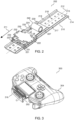
- FIG. 2 shows an extendable mechanism 202 for a body structure according to various embodiments.
- the extendable mechanism 102 may include an extension member 210 according to various embodiments.
- the extendable member 210 may be of an elongate shape, such as an elongate plate or an elongate panel. Accordingly, the extendable member 210 may be extendable in a lengthwise direction along a longitudinal axis 212 of the extendable member 210.
- the extendable mechanism 202 may further include a link member 220 which may be provided with an extension-member-guide element 222.
- the extension-member-guide element 222 may be configured for guiding a movement of the extension member 210 as the extension member 210 is being extended or drawn out.
- the extension member 210 may be in engagement with the extension-member-guide element 222 of the link member 220 in a manner so as to be retractably extendable from the link member 220 (or retractably movable relative to the link member 220) in an extension direction 211 along the longitudinal axis 212 of the extension member 210.
- the extension-member-guide element 222 may guide a relative movement between the extension member 210 and the link member 220 of the extendable mechanism 202 such that the extension member 210 may be extendable relative to the link member 220 (or the extension member 210 may be extended or drawn out from the link member 220).
- the extension-member-guide element 222 of the link member 220 and a link body 224 of the link member 220 may be separate parts of the link member 220.
- the extension-member-guide element 222 and the link body 224 may be two separate parts fixedly coupled or joined or connected or attached to each other so as to form the link member 220.
- the link body 224 of the link member 220 may be of an elongate shape, such as an elongate plate or an elongate panel.
- the extendable mechanism 202 may further include a link-member-guide element 230.
- the link-member-guide element 230 may be for being disposed at the body structure.
- the link-member-guide element 230 may be a separate part from the body structure such that the link-member-guide element 230 may be for being attached or coupled or fixed or joined or connected to the body structure.
- the link-member-guide element 230 may serve to couple or join or fix or attach or connect the extendable mechanism 202 to the body structure.
- the extendable mechanism 202 may include a mounting plate 232 for being configured to couple the link-member-guide element 230 to the body structure.
- the link member 220 may be in engagement with the link-member-guide element 230 in a manner so as to be retractably extendable from the link-member-guide element 230 (or retractably movable relative to the link-member-guide element 230) in the extension direction 211 of the extension member 210.
- the link-member-guide element 230 may guide a relative movement between the link member 220 and the link-member-guide element 230 such that the link member 220 may be extendable relative to the link-member-guide element 230 (or the link member 220 may be extended or drawn out from the link-member-guide element 230).
- the relative movement between the link member 220 and the link-member-guide element 230 may be parallel to the relative movement between the extension member 210 and the link member 220.
- the extension member 210 of the extendable mechanism 202 may serve as a main extension, and the link member 220 may serve as a secondary extension.
- the extension member 210 and the link member 220 which may be elongated in shape, may be arranged in an overlapping or a stacked configuration lengthwise such that, when the extendable mechanism 202 is in the retracted state, the link member 220 may extend over and cover a portion of the extension member 210.
- the extendable mechanism 202 may provide a compact mechanism with dual-stage extensions such that the extendable mechanism 202 may only occupy a small area in the retracted state.
- the extendable mechanism 202 may further include a biasing member 240.
- the biasing member 240 may be for being arranged between the link member 220 and the body structure.
- the biasing member 240 may serve to apply a biasing force on the link member 220 in a direction opposite to the extension direction 211 of the elongate extension member 210.
- the biasing member 240 may serve to provide a retraction force, which may be against the extension movement of the link member 220, for retracting the link member 220 relative to the link-member-guide element 230.
- the biasing member 240 may include a tape spring or a clock spring with one end (or an outer end) attached or fixed or coupled or joined to the link member 220.
- the extension member 210 may include a stopper element 214 at an end (or an inner end) of the extension member 210 opposite the extension direction 211 of the extension member 210.
- the stopper element 214 may include a protrusion projecting at least substantially perpendicular to the extension member 210 so as to provide a physical barrier or limit between the extension member 210 and the extension-member-guide element 222 of the link member 220 for preventing the entire extension member 210 from being pulled out of the extension-member-guide element 222 of the link member 220.
- the stopper element 214 may fix or set a maximum relative extension between the extension member 210 and the extension-member-guide element 222 of the link member 220.
- any further force applied to the extension member 210 in the extension direction 211 may cause the force to be transferred to the link member 220 for extending or drawing out the link member 220 relative to the link-member-guide element 230. Accordingly, in use, the extension member 210 may be extended or drawn out first before the link member 220 may be extended or drawn out from the link-member-guide element 230.
- the extension member 210 and the extension-member-guide element 222 of the link member 220 may be engaged in a tongue and groove sliding engagement.
- the extension member 210 may include a pair of tongue projections 217, 219 along opposite side edges of the extension member 210 parallel to the longitudinal axis 212 or the extension direction 211 of the extension member 210
- the extension-member-guide element 222 of the link member 220 may include a pair of grooves 221, 223 facing towards each other and parallel to the longitudinal axis 212 or the extension direction 211 of the extension member 210.
- the pair of tongue projections 217, 219 of the extension member 210 may be configured to slidably engage with the pair of grooves 221, 223 of the extension-member-guide element 222 of the link member 220 such that they may be slidable relative to each other.
- each of the pair of tongue projections 217, 219 of the extension member 210 may have a substantially L-shaped cross-section while each of the pair of grooves 221, 223 of the extension-member-guide element 222 of the link member 220 may have a substantially C-shaped cross-section.
- the pair of tongue projections 217, 219 of the extension member 210 and the pair of grooves 221, 223 of the extension-member-guide element 122 of the link member 220 may enable a stable and wobble-free relative sliding movement between the extension member 210 and the link member 220.
- the link member 220 and the link-member-guide element 230 may be engaged in a tongue and groove sliding engagement.
- the link member 220 may include a pair of tongue projections 227, 229 extending along opposite side edges of the link member 220 parallel to the longitudinal axis 212 or the extension direction 211 of the extension member 210
- the link-member-guide element 230 may include a pair of grooves 231, 233 facing towards each other and parallel to the longitudinal axis 212 or the extension direction 211 of the extension member 210.
- the pair of tongue projections of the link member 220 may be configured to slidably engage with the pair of grooves 231, 233 of the link-member-guide element 230 such that they may be slidable relative to each other.
- each of the pair of tongue projections 227, 229 of the link member 220 may have a substantially L-shaped cross-section while each of the pair of grooves 231, 233 of the link-member-guide element 230 may have a substantially C-shaped cross-section.
- the pair of tongue projections 227, 229 of the link member 220 and the pair of grooves 231, 233 of the link-member-guide element 230 may enable a stable and wobble-free relative sliding movement between the link member 220 and the link-member-guide element 230.
- the extension member 210 may include two or more holes 218 lined along a length of the extension member 210 at regular interval.
- the two or more holes 218 may be for cooperating with a spring-loaded projection 444 (e.g. see FIG. 4A ) to serve as intermediate stoppages as the as the extension member 210 is being extended or drawn out so as to avoid the extension member 210 from being pulled out entirely at once.
- the two or more holes along the extension member 210 may provide discrete interval or length at which the extension movement of the extension member 210 may be disrupted or interrupted.
- FIG. 3 shows a controller 300 with the extendable mechanism 202 of FIG. 2 according to various embodiments.
- the controller 300 may include a controller body 304.
- the extendable mechanism 202 may be disposed within or inside the controller body 304. Accordingly, the extendable mechanism 202 may be mounted or secured or attached or coupled to an interior of the controller body 304. According to various embodiments, the extendable mechanism 202 may serve to provide an extension to the controller body 304. Accordingly, while the extendable mechanism 202 may be within the controller body 304 in the retracted state, the extendable mechanism 202 may be extended or drawn out of the controller body 304 in the extended state. In FIG.
- the extendable mechanism 202 is shown to be disposed in the center region of the controller body 304. According to various embodiments, the extendable mechanism 202 may be disposed at other locations of the controller body 304 depending on the configuration of the controller body 304.
- the controller 300 as shown in FIG. 3 is provided by way of example only and not limitation.
- the extendable mechanism 202 may include a protruding lip 316 at an outer end of the extendable mechanism 202 with respect to the controller body 304. Accordingly, with reference to FIG. 2 , the protruding lip 316 may be disposed at an outer end of the extension member 210 of the extendable mechanism 202 in the extension direction 211 of the extension member 210. The protruding lip 316 may be at least substantially perpendicular to the extension member 210.
- the protruding lip 316 may serve to contact an edge of an object, such as the mobile phone or the personal electronic device, being placed between the protruding lip 316 of the extension member 210 of the extendable mechanism 202 and the controller body 304 such that the object may be removably attached or secured or coupled between the protruding lip 316 of the extendable mechanism 202 and the controller body 304.
- the protruding lip 316 and an extension body 215 of the extension member 210 may be separate parts. Accordingly, the protruding lip 316 may be joined or coupled or fixed or connected or attached to the extension body 215 of the extension member 210.
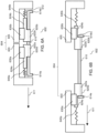
- FIG. 4A shows a cross sectional view of the controller 300 of FIG. 3 with the extendable mechanism 202 of FIG. 2 in a retracted state according to various embodiments.
- FIG. 4B shows a cross sectional view of the controller 300 of FIG. 3 with the extendable mechanism 202 of FIG. 2 in an extended state according to various embodiments.
- the controller 300 may include the controller body 304 and the extendable mechanism 202 of FIG. 2 .
- the extendable mechanism 202 may include the extension member 210, the link member 220, the link-member-guide element 230, and the biasing member 240.
- the link-member-guide element 230 of the extendable mechanism 202 may be disposed at the controller body 304.
- the link-member-guide element 230 of the extendable mechanism 202 may be mounted or secured or fixed or attached or coupled to an interior portion of the controller body 304 such that the link-member-guide element 230 may be fixed (or non-movable relative) to the controller body 304. Accordingly, with the link-member-guide element 230 of the extendable mechanism 202 fixed to the controller body 304, the extension member 210 and the link member 220 of the extendable mechanism 202 may be extendable relative to the controller body 304.
- the biasing member 240 of the extendable mechanism 202 may be arranged between the link member 220 of the extendable mechanism 202 and the controller body 304. According to various embodiments, one end of the biasing member 240 may be coupled to the link member 220 of the extendable mechanism 202 and another end of the biasing member 240 may be coupled to the controller body 304. According to various embodiments, the biasing member 240 may be configured to apply a biasing force on the link member 220 in a direction opposite to the extension direction 211 of the extension member 210.
- the biasing force of the biasing member 240 may provide a retraction force for retracting the link member 220 as the link member 230 is extended or drawn out from the link-member-guide element 220 which may be fixed to the controller body 304.
- the extendable mechanism 202 may be free of biasing member between the extension member 210 and the link member 220. Accordingly, the extendable mechanism 202 may be free of a biasing force being applied to retract the extension member 210 relative to the link member 220.
- a user may easily extend or draw out the extension member 210 from the link member 220 without risk of having any of the user's fingers being clamped between the protruding lip 316 and the controller body 304.
- the user may then apply a force to the extension member 210 so as to overcome the biasing force applied on the link member 220 in order to extend or draw out the link member 220 with respect to the link-member-guide element 230 (or the controller body 304) for further extending the extendable mechanism 202 such that the object (e.g. mobile phone or personal electronic device) may be placed between the protruding lip 316 and the controller body 304. Accordingly, the object may be retained between the protruding lip 316 and the controller body 304 by the biasing force acting on the link member 220 of the extendable mechanism 202.
- the object e.g. mobile phone or personal electronic device
- the controller body 304 may include the spring-loaded projection 445 disposed at the controller body 304.
- the spring-loaded projection 445 may be disposed inside the controller body 304 or at an interior portion of the controller body 304.
- the spring-loaded projection 445 may be disposed at the interior portion of the controller body 304 which may be immediately adjacent the extension member 210 of the extendable mechanism 202 when the extendable mechanism 202 is in the retracted state.
- the spring-loaded projection 445 may be configured to cooperate with the two or more holes 218 of the extension member 210 as the extension member 210 is being extended from the controller body 304.
- the cooperation between the two or more holes 218 along the extension member 210 and the spring-loaded projection 445 may serve to provide intermediate stoppages as the extension member 210 is being extended or drawn out from the controller body 304 so as to avoid the extension member 210 from being pulled out from the controller body 304 all at once.
- the spring-loaded projection 445 may include a ball or a rounded-tip pin or a finger-like projection placed on a spring.
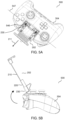
- FIG. 5A and FIG. 5B show a controller 500 with the extendable mechanism 202 of FIG. 2 configured to be pivotable according to various embodiments.
- the hinge joint 546 may couple the link-member-guide element 230 of the extendable mechanism 202 to the controller body 304 such that the link-member-guide element 230 may be pivotable about a pivot-axis 547 perpendicular to the extension direction 211 of the extension member 210 of the extendable mechanism 202 to incline the link-member-guide element 230 with respect to the controller body 304.
- the link-member-guide element 230 of the extendable mechanism 202 may be pivotable with respect to the controller body 304 about the hinge joint 546.
- the hinge joint 546 may include a hinge, or a spring-loaded hinge.
- the link-member-guide element 230 may be configured to be inclined with respect to a main surface of controller body 304, wherein the main surface is a surface of the controller body 304 with the control buttons and/or joysticks.
- the extension member 210 and/or the link member 220 of the extendable mechanism 202 may be required to be extended or drawn out with respect to the controller body 304 before the link-member-guide element 230 may be pivoted so as to be inclined with respect to the controller body 304. Accordingly, when the link-member-guide element 230 is pivoted to be inclined with respect to the controller body 304, the extendable mechanism 202 may be inclined with respect to the controller body 304 as shown in FIG. 5B .
- FIG. 6A shows a schematic diagram of an extendable mechanism 602 in a retracted state according to various embodiments.
- FIG. 6B shows a schematic diagram of the extendable mechanism 602 of FIG. 6A in an extended state according to various embodiments.
- the extendable mechanism 602 may be for being arranged between a first part 603 of a body structure 604 and a second part 605 of the body structure 604. As shown, one end of the extendable mechanism 602 may be for being mounted or secured or attached or coupled to the first part 603 of the body structure 604, and another end of the extendable mechanism 602 may be for being mounted or secured or attached or coupled to the second part 605 of the body structure 604.
- the extendable mechanism 602 may serve to provide an extendable link or bridge between the first part 603 of the body structure 604 and the second part 605 of the body structure 604.
- the second part 605 of the body structure 604 may be a main part of the body structure 604 and the first part 603 of the body structure 604 may be an auxiliary part of the body structure 604.
- an extension direction 611 of the extendable mechanism 602 may refer to a direction in which the first part 603 (or the auxiliary part) of the body structure 604 may be moved relatively away from the second part 605 (or the main part) of the body structure 604 (i.e.
- first part 603 and the second part 605 of the body structure 604 may be of any shape or size or configuration depending on what is the device embodied by the body structure 604.
- the body structure 604 as shown in FIG. 6A and FIG. 6B is provided by way of example only and not limitation.
- the body structure 604 may be a body of a game controller wherein a mobile phone or a personal electronic device may be sandwiched between the first part 603 of the body structure 604 and the second part 605 of the body structure 604.
- the extendable mechanism 602 between the first part 603 (or the auxiliary part) of the body structure 604 and the second part 605 (or the main part) of the body structure 604 may include an extension member 610 according to various embodiments.
- the extension member 610 may be shaped or dimensioned or configured such that it may be for being concealed or contained or kept or held within the body structure 604 in the retracted state of the extendable mechanism 602, and may be for being extended between the first part 603 of the body structure 604 and the second part 605 of the body structure 604 in the extended state of the extendable mechanism 602.
- the extension member 610 may serve to be a part of the extendable mechanism 602 that may be a physically extension between the first part 603 of the body structure 604 and the second part 605 of the body structure 604.
- the extendable member 610 may be of an elongate shape.
- the extendable member 610 may be an elongate plate or an elongate panel.
- the first part 603 of the body structure 604 may be extendable from the second part 605 of the body structure 604 via the extendable mechanism 602 in a lengthwise direction along a longitudinal axis 612 of the extendable member 610.
- the extendable mechanism 602 may further include a first link member 620a (or an auxiliary link member) which may be provided with a first extension-member-guide element 622a (or an auxiliary extension-member-guide element).
- the first extension-member-guide element 622a may be configured for guiding a relative movement of the first link member 620a with respect to the extension member 610.
- the extension member 610 may be in engagement with the first extension-member-guide element 622a of the first link member 620a in a manner such that the first link member 620a may be retractably movable relative to the extension member 610 in the extension direction 611 of the extendable mechanism 602 along the axis of the extension member 610.
- the first extension-member-guide element 622a may guide a relative movement between the first link member 620a and the extension member 610 of the extendable mechanism 602 such that the first link member 620a may be movable relative to the extension member 610.
- the extension direction 611 of the extendable mechanism 602 may be along the longitudinal axis 612 of the elongate extension member 610.
- the first extension-member-guide element 622a of the first link member 620a may be a separate part from a first link body 624a of the first link member 620a.
- first extension-member-guide element 622a and the first link body 624a may be two separate parts fixedly coupled or joined or connected or attached to each other so as to form the first link member 620a.
- first extension-member-guide element 622a and the first link body 624a may also be integrally molded or formed as a single unitary piece to form the first link member 620a.
- the extendable mechanism 602 may further include a first-link-member-guide element 630a (or an auxiliary-link-member-guide element).
- the first-link-member-guide element 630a may be for being disposed at the first part 603 of the body structure 604.
- the first-link-member-guide element 630a may be a separate part from the first part 603 of the body structure 604, whereby the first-link-member-guide element 630a may be for being attached or coupled or fixed or joined or connected to the first part 603 of the body structure 604, or an integral portion of first part 603 of the body structure 604, whereby the first-link-member-guide element 630a may be integrally molded or formed with the first part 603 of the body structure 604 as a single unitary piece.
- the first link member 620a may be in engagement with the first-link-member-guide element 630a in a manner such that the first-link-member-guide element 630a may be retractably movable relative to the first link member 620a in the extension direction 611 of the extendable mechanism 602. Accordingly, the first-link-member-guide element 630a may move relative to the first link member 620a.
- the relative movement between the first-link-member-guide element 630a and the first link member 620a may be parallel to the relative movement between the first link member 620a and the extension member 610.
- the extendable mechanism 602 may further include a first biasing member 640a (or an auxiliary biasing member).
- the first biasing member 640a may be for being arranged between the first link member 620a and the first part 603 of the body structure 604.
- the first biasing member 640a may serve to apply a biasing force on the first link member 620a in the extension direction 611 of the extension member 610.
- the first biasing member 640a may serve to provide a pulling force on the first link member 620a such that the pulling force may move the first link member 620a relative to the extension member 610 in the extension direction.
- the first biasing member 640a may be between the first link member 620a and the first part 603 of the body structure 604, the biasing force of the biasing member 640a may be against the relative movement between the first-link-member-guide element 630a and the first link member 620a.
- the first biasing member 640a may include a tape spring, a clock spring, a coil spring, a torsion spring, a compression spring, a tension spring, or any combination thereof.
- the extendable mechanism 602 may further include a second link member 620b (or a main link member) which may be provided with a second extension-member-guide element 622b (or a main extension-member-guide element).
- the second extension-member-guide element 622b may be configured for guiding a relative movement of the extension member 610 with respect to the second link member 620b.
- the extension member 610 may be in engagement with the second extension-member-guide element 622b of the second link member 620b in a manner such that the extension member 610 may be retractably movable relative to the second link member 620b in the extension direction 611 of the extendable mechanism 602 along the axis of the extension member 610.
- the second extension-member-guide element 622b may guide a relative movement between the extension member 610 and the second link member 620b such that the extension member 610 may be movable relative to the second link member 620b.
- the extension direction 611 of the extendable mechanism 602 may be along the longitudinal axis 612 of the elongate extension member 610.
- the second extension-member-guide element 622b of the second link member 620b may be a separate part from a second link body 624b of the second link member 620b.
- the second extension-member-guide element 622b and the second link body 624b may be two separate parts fixedly coupled or joined or connected or attached to each other so as to form the second link member 620b.
- the second extension-member-guide element 622b and the second link body 624b may also be integrally molded or formed as a single unitary piece to form the second link member 620b.
- the extendable mechanism 602 may further include a second-link-member-guide element 630b (or a main-link-member-guide element).
- the second-link-member-guide element 630b may be for being disposed at the second part 605 of the body structure 604.
- the second-link-member-guide element 630b may be a separate part from the second part 605 of the body structure 604, whereby the second-link-member-guide element 630b may be for being attached or coupled or fixed or joined or connected to the second part 605 of the body structure 604, or an integral portion of second part 605 of the body structure 604, whereby the second-link-member-guide element 630b may be integrally molded or formed with the second part 605 of the body structure 604 as a single unitary piece.
- the second-link-member-guide element 630b may be in engagement with the second link-member 620b in a manner such that the second link member 620b may be retractably movable relative to the second-link-member-guide element 630b in the extension direction 611 of the extendable mechanism 602. Accordingly, the second link member 620b may move relative to the second-link-member-guide element 630b.
- the relative movement between the second link member 620b and the second-link-member-guide element 630b may be parallel to the relative movement between the extension member 610 and the second link member 620b.
- the extendable mechanism 602 may further include a second biasing member 640b (or a main biasing member).
- the second biasing member 640b may be for being arranged between the second link member 620b and the second part 605 of the body structure 604.
- the second biasing member 640b may serve to apply a biasing force on the second link member 620b in a direction opposite to the extension direction 611 of the extendable mechanism 602.
- the second biasing member 640b may serve to provide a retraction force, which may be against the extension movement of the second link member 620b from the second-link-member-guide element 630b, for retracting the second link member 620b towards the second part 605 of the body structure 604.
- the second biasing member 640b may include a tape spring, a clock spring, a coil spring, a torsion spring, a compression spring, a tension spring, or any combination thereof.
- the extension member 610 of the extendable mechanism 602 may serve as a primary extension of the extendable mechanism 602 between the first part 603 of the body structure 604 and the second part 605 of the body structure 604.
- the first link member 620a and the second link member 620b may serve as secondary extensions from the extension member 610 of the extendable mechanism 602.
- the extension member 610 and the first link member 620a may be arranged in an overlapping or a stacked configuration.
- the extension member 610 and the second link member 620b may also be arranged in an overlapping or a stacked configuration.
- each of the first link member 620a and the second link member 620b may extend over and cover respective portions of the extension member 610.
- the extendable mechanism 602 may provide a compact mechanism with overlapping or stacked extensions for the body structure 604.
- the extension member 610 may include at least two stopper elements 614a and 614b, one stopper element 614a, 614b at each end of the extension member 610.
- each of the stopper elements 614a, 614b may include a protrusion projecting at least substantially perpendicular from the extension member 610 so as to provide a physical barrier or limit between the extension member 610 and the respective first and second extension-member-guide element 622a, 622b of the respective first and second link member 620a, 620b for preventing the extension member 610 from being pulled out or separated from the respective first and second extension-member-guide element 622a, 622b of the first and second link member 620a, 620b.
- the respective stopper element 614a, 614b may fix or set a maximum relative movable distance between the extension member 610 and the respective first and second extension-member-guide element 622a, 622b of the respective first and second link member 620a, 620b.
- the extendable mechanism 602 may be free of biasing member between the first link member 620a and the extension member 610. Accordingly, the extendable mechanism 602 may be free of a biasing force being applied to retract the first link member 620a relative to the extension member 610. According to various embodiments, the extendable mechanism 602 may also be free of biasing member between the extension member 610 and the second link member 620b. Accordingly, the extendable mechanism 602 may be free of a biasing force being applied to retract the extension member 610 relative to the second link member 620b.
- a user may easily pull apart the first part 603 of the body structure 604 from the second part 605 of the body structure 604 via the extendable mechanism 602 in a first stage such that the extension member 610 may be fully extended between the first link member 620a and the second link member 620b. Subsequently, with the extension member 610 fully extended between the first link member 620a and the second link member 620b, the user may then apply a force to pull apart the first part 603 of the body structure 604 from the second part 605 of the body structure 604 so as to overcome the respective biasing forces applied on the first link member 620a and the second link member 620b in order to further extend the extendable mechanism 602 such that an object (e.g.
- first part 603 of the body structure 604 may be placed between first part 603 of the body structure 604 and the second part 605 of the body structure 604. Accordingly, the object may be retained between the first part 603 of the body structure 604 and the second part 605 of the body structure 604 by the biasing forces acting on the respective first and second link member 620a, 620b.
- the extension member 610 may be engaged with the first extension-member-guide element 622a of the first link member 620a and the second extension-member-guide element 622b of the second link member 620b via tongue and groove sliding engagements. Accordingly, the extension member 610 may include a pair of tongue projections along opposite side edges of the extension member 610 parallel to the extension direction 611 of the extendable mechanism 602. The first extension-member-guide element 622a of the first link member 620a may include a pair of grooves facing towards each other and parallel to the extension direction 611 of the extension member 110.
- the second extension-member-guide element 622b of the second link member 620b may include a pair of grooves facing towards each other and parallel to the extension direction 611 of the extension member 610. Accordingly, the pair of grooves of the first extension-member-guide element 622a of the first link member 620a may be engaged with the respective tongue projections of the extension member 610 so as to be slidable relative to the respective tongue projections of the extension member 610. The tongue projections of the extension member 610 may then be engaged with the respective grooves of the second extension-member-guide element 622b of the second link member 620a so as to be slidable relative to the respective grooves of the second extension-member-guide element 622b of the second link member 620a.
- the extension member 610 may include a pair of grooves along opposite side edges of the extension member 610 parallel to the extension direction 611 of the extendable mechanism 602.
- the first extension-member-guide element 622a of the first link member 620a may include a pair of tongue projections directed towards each other and parallel to the extension direction 611 of the extension member 110.
- the second extension-member-guide element 622b of the second link member 620b may include a pair of tongue projections directed towards each other and parallel to the extension direction 611 of the extension member 610.
- the pair of tongue projections of the first extension-member-guide element 622a of the first link member 620a may be engaged with the respective grooves of the extension member 610 so as to be slidable relative to the respective grooves of the extension member 610.
- the pair of grooves of the extension member 610 may then be engaged with the respective tongue projections of the second extension-member-guide element 622b of the second link member 620a so as to be slidable relative to the respective tongue projections of the second extension-member-guide element 622b of the second link member 620a.
- the tongue and groove sliding engagement may include a protrusion and groove sliding arrangement, or a dovetail tongue and groove sliding arrangement, or a T-shaped tongue and groove sliding arrangement, or a J-shaped tongue and groove sliding arrangement, or an L-shaped tongue and groove sliding arrangement, or a hooked-like tongue and groove sliding arrangement, or any other suitable sliding arrangement.
- the first link member 620a and the first link-member-guide element 630a may be engaged in a tongue and groove sliding engagement.
- the first link member 620a may include a pair of tongue projections extending along opposite side edges of the first link member 620a parallel to the extension direction 611 of the extension member 610
- the first link-member-guide element 630a may include a pair of grooves facing towards each other and parallel to the extension direction 611 of the extension member 610.
- the pair of tongue projections of the first link member 620a and the pair of grooves of the first link-member-guide element 630a may be configured to engage such that the respective tongue projections are slidable relative to the corresponding groove.
- the first link member 620a may include a pair of grooves extending along opposite side edges of the first link member 620a parallel to the extension direction 611 of the extension member 610, and the first link-member-guide element 630a may include a pair of tongue projections directed towards each other and parallel to the extension direction 611 of the extension member 610. Accordingly, the pair of grooves of the first link member 620a and the pair of tongue projections of the first link-member-guide element 630a may be configured to engage with each other such that respective tongue projections are slidable relative to the corresponding groove.
- the tongue and groove sliding engagement may include a protrusion and groove sliding arrangement, or a dovetail tongue and groove sliding arrangement, or a T-shaped tongue and groove sliding arrangement, or a J-shaped tongue and groove sliding arrangement, or an L-shaped tongue and groove sliding arrangement, or a hooked-like tongue and groove sliding arrangement, or any other suitable tongue and groove sliding arrangement.
- the second link member 620b and the second link-member-guide element 630b may be engaged in a tongue and groove sliding engagement.
- the second link member 620b may include a pair of tongue projections extending along opposite side edges of the second link member 620b parallel to the extension direction 611 of the extension member 610
- the second link-member-guide element 630b may include a pair of grooves facing towards each other and parallel to the extension direction 611 of the extension member 610.
- the pair of tongue projections of the second link member 620b and the pair of grooves of the second link-member-guide element 630b may be configured to engage such that the respective tongue projections are slidable relative to the corresponding groove.
- the second link member 620b may include a pair of grooves extending along opposite side edges of the second link member 620b parallel to the extension direction 611 of the extension member 610, and the second link-member-guide element 630b may include a pair of tongue projections directed towards each other and parallel to the extension direction 611 of the extension member 610. Accordingly, the pair of grooves of the second link member 620b and the pair of tongue projections of the second link-member-guide element 630b may be configured to engage with each other such that respective tongue projections are slidable relative to the corresponding groove.
- the tongue and groove sliding engagement may include a protrusion and groove sliding arrangement, or a dovetail tongue and groove sliding arrangement, or a T-shaped tongue and groove sliding arrangement, or a J-shaped tongue and groove sliding arrangement, or an L-shaped tongue and groove sliding arrangement, or a hooked-like tongue and groove sliding arrangement, or any other suitable tongue and groove sliding arrangement.
- FIG. 7 shows an extendable mechanism 702 according to various embodiments.
- the extendable mechanism 702 may include an extension member 710 according to various embodiments.
- the extendable member 710 may be of an elongate shape, such as an elongate plate or an elongate panel.
- the extendable mechanism 702 may further include a first link member 720a which may be provided with a first extension-member-guide element 722a.
- the first extension-member-guide element 722a may be configured for guiding a relative movement of the first link member 720a with respect to the extension member 710.
- the extension member 710 may be in engagement with the first extension-member-guide element 722a of the first link member 720a in a manner such that the first link member 720a may be retractably movable relative to the extension member 710 in the extension direction 711 of the extendable mechanism 702 along the longitudinal axis 712 of the extension member 710.
- the first extension-member-guide element 722a may guide a relative movement between the first link member 720a and the extension member 710 of the extendable mechanism 702 such that the first link member 720a may be movable relative to the extension member 710.
- the first extension-member-guide element 722a of the first link member 720a may be a separate part from a first link body 724a of the first link member 720a.
- the first extension-member-guide element 722a and the first link body 724a may be two separate parts fixedly coupled or joined or connected or attached to each other so as to form the first link member 720a.
- the extendable mechanism 702 may further include a first-link-member-guide element 730a.
- the first-link-member-guide element 730a may be for being disposed at a first part of a body structure. As shown, according to various embodiments, the first-link-member-guide element 730a may be a separate part from the first part of the body structure. Accordingly, the first-link-member-guide element 730a may be for being attached or coupled or fixed or joined or connected to the first part of the body structure.
- the first link member 720a may be in engagement with the first-link-member-guide element 730a in a manner such that the first-link-member-guide element 730a may be retractably movable relative to the first link member 720a in the extension direction 711 of the extendable mechanism 702. Accordingly, the first-link-member-guide element 730a may move relative to the first link member 720a.
- the relative movement between the first-link-member-guide element 730a and the first link member 720a may be parallel to the relative movement between the first link member 720a and the extension member 710.
- the extendable mechanism 702 may further include a first biasing member 740a.
- the first biasing member 740a may be for being arranged between the first link member 720a and the first part of the body structure.
- the first biasing member 740a may serve to apply a biasing force on the first link member 720a in the extension direction 711 of the extension member 710.
- the first biasing member 740a may serve to provide a pulling force on the first link member 720a such that the pulling force may move the first link member 720a relative to the extension member 710 in the extension direction.
- the biasing force of the biasing member 740a may be against the relative movement between the first-link-member-guide element 730a and the first link member 720a.
- the first biasing member 740a may include a tape spring, or a clock spring.
- the extendable mechanism 702 may further include a second link member 720b which may be provided with a second extension-member-guide element 722b.
- the second extension-member-guide element 722b may be configured for guiding a relative movement of the extension member 710 with respect to the second link member 720b.
- the extension member 710 may be in engagement with the second extension-member-guide element 722b of the second link member 720b in a manner such that the extension member 710 may be retractably movable relative to the second link member 720b in the extension direction 711 of the extendable mechanism 702 along the longitudinal axis 712 of the extension member 710.
- the second extension-member-guide element 722b may guide a relative movement between the extension member 710 and the second link member 720b such that the extension member 710 may be movable relative to the second link member 720b.
- the second extension-member-guide element 722b of the second link member 720b may be a separate part from a second link body 724b of the second link member 720b.
- the second extension-member-guide element 722b and the second link body 724b may be two separate parts fixedly coupled or joined or connected or attached to each other so as to form the second link member 720b.
- the extendable mechanism 702 may further include a second-link-member-guide element 730b.
- the second-link-member-guide element 730b may be for being disposed at a second part of the body structure.
- the second-link-member-guide element 730b may be a separate part from the second part of the body structure. Accordingly, the second-link-member-guide element 730b may be for being attached or coupled or fixed or joined or connected to the second part of the body structure.
- the second-link-member-guide element 730b may be in engagement with the second link-member 720b in a manner such that the second link member 720b may be retractably movable relative to the second-link-member-guide element 730b in the extension direction 711 of the extendable mechanism 702. Accordingly, the second link member 720b may move relative to the second-link-member-guide element 730b.
- the relative movement between the second link member 720b and the second-link-member-guide element 730b may be parallel to the relative movement between the extension member 710 and the second link member 720b.
- the extendable mechanism 702 may further include a second biasing member 740b.
- the second biasing member 740b may be for being arranged between the second link member 720b and the second part of the body structure.
- the second biasing member 740b may serve to apply a biasing force on the second link member 720b in a direction opposite to the extension direction 711 of the extendable mechanism 702.
- the second biasing member 740b may serve to provide a retraction force, which may be against the extension movement of the second link member 720b from the second-link-member-guide element 730b, for retracting the second link member 720b towards the second part of the body structure.
- the second biasing member 740b may include a tape spring or a clock spring.
- the extension member 710 of the extendable mechanism 702 may serve as a primary extension of the extendable mechanism 702.
- the first link member 720a and the second link member 720b may serve as secondary extensions from the extension member 610 of the extendable mechanism 702.
- the extension member 710 and the first link member 720a may be arranged in an overlapping or a stacked configuration.
- the extension member 710 and the second link member 720b may also be arranged in an overlapping or a stacked configuration. Accordingly, when the extendable mechanism 702 is in the retracted state, each of the first link member 720a and the second link member 720b may extend over and cover respective portions of the extension member 710.
- the extendable mechanism 702 may provide a compact mechanism with overlapping or stacked extensions.
- the extension member 710 may include at least two stopper elements 714a and 714b, one stopper element 714a, 714b at each end of the extension member 710.
- each of the stopper elements 714a, 714b may include a protrusion projecting at least substantially perpendicular from the extension member 710 so as to provide a physical barrier or limit between the extension member 710 and the respective first and second extension-member-guide element 722a, 722b of the respective first and second link member 720a, 720b for preventing the extension member 710 from being pulled out or separated from the respective first and second extension-member-guide element 722a, 722b of the first and second link member 720a, 720b.
- the respective stopper element 714a, 714b may fix or set a maximum relative movable distance between the extension member 710 and the respective first and second extension-member-guide element 722a, 722b of the respective first and second link member 720a, 720b.
- the extendable mechanism 702 may be free of biasing member between the first link member 720a and the extension member 710. Accordingly, the extendable mechanism 702 may be free of a biasing force being applied to retract the first link member 720a relative to the extension member 710. According to various embodiments, the extendable mechanism 702 may also be free of biasing member between the extension member 710 and the second link member 720b. Accordingly, the extendable mechanism 702 may be free of a biasing force being applied to retract the extension member 710 relative to the second link member 720b. Hence, a user may easily pull apart the extendable mechanism 702 in a first stage such that the extension member 710 may be fully extended between the first link member 720a and the second link member 720b.
- the user may then apply a force to overcome the respective biasing forces applied on the first link member 720a and the second link member 720b in order to further extend the extendable mechanism 702.
- the extension member 710 may be engaged with the first extension-member-guide element 722a of the first link member 720a and the second extension-member-guide element 722b of the second link member 720b via tongue and groove sliding engagements. Accordingly, the extension member 710 may include a pair of tongue projections along opposite side edges of the extension member 710 parallel to the extension direction 711 of the extendable mechanism 702. The first extension-member-guide element 722a of the first link member 720a may include a pair of grooves facing towards each other and parallel to the extension direction 711 of the extension member 710.
- the second extension-member-guide element 722b of the second link member 720b may include a pair of grooves facing towards each other and parallel to the extension direction 711 of the extension member 710. Accordingly, the pair of grooves of the first extension-member-guide element 722a of the first link member 720a may be engaged with the respective tongue projections of the extension member 710 so as to be slidable relative to the respective tongue projections of the extension member 710. The tongue projections of the extension member 610 may then be engaged with the respective grooves of the second extension-member-guide element 722b of the second link member 720a so as to be slidable relative to the respective grooves of the second extension-member-guide element 722b of the second link member 720a.
- the first link member 720a and the first link-member-guide element 730a may be engaged in a tongue and groove sliding engagement.
- the first link member 720a may include a pair of tongue projections extending along opposite side edges of the first link member 720a parallel to the extension direction 711 of the extension member 710
- the first link-member-guide element 730a may include a pair of grooves facing towards each other and parallel to the extension direction 711 of the extension member 710.
- the pair of tongue projections of the first link member 720a and the pair of grooves of the first link-member-guide element 730a may be configured to engage such that the respective tongue projections are slidable relative to the corresponding groove.
- the second link member 720b and the second link-member-guide element 730b may be engaged in a tongue and groove sliding engagement.
- the second link member 720b may include a pair of tongue projections extending along opposite side edges of the second link member 720b parallel to the extension direction 711 of the extension member 710
- the second link-member-guide element 730b may include a pair of grooves facing towards each other and parallel to the extension direction 711 of the extension member 710.
- the pair of tongue projections of the second link member 720b and the pair of grooves of the second link-member-guide element 730b may be configured to engage such that the respective tongue projections are slidable relative to the corresponding groove.
- FIG. 8 shows a controller 800 with the extendable mechanism 702 of FIG. 7 according to various embodiments.
- the controller 800 may include a controller body 804 having a first part 803 (or an auxiliary part) and a second part 805 (or a main part).
- the extendable mechanism 702 may be disposed within or inside the controller body 804. Accordingly, the extendable mechanism 702 may be mounted or secured or attached or coupled to an interior of the controller body 804. According to various embodiments, the extendable mechanism 702 may serve to provide an extension link or bridge between the first part 803 of the controller body 804 and the second part 805 of the controller body 804.
- the extendable mechanism 702 may be within the controller body 804 in the retracted state, the extendable mechanism 702 may be exposed and extended between the first part 803 of the controller body 804 and the second part 805 of the controller body 804 in the extended state. According to various embodiments, the extendable mechanism 702 may be disposed at any locations of the controller body 804 depending on the configuration of the controller body 804.
- the controller 800 as shown in FIG. 8 is provided by way of example only and not limitation.
- FIG. 9A shows a cross sectional view of the controller 800 of FIG. 8 with the extendable mechanism 702 of FIG. 7 in a retracted state according to various embodiments.
- FIG. 9B shows a cross sectional view of the controller 800 of FIG. 8 with the extendable mechanism 702 of FIG. 7 in an extended state according to various embodiments.
- the controller 800 may include the controller body 804 having the first part 803 and the second part 805, and the extendable mechanism 702 of FIG. 7 disposed between the first part 803 of the controller body 804 and the second part 805 of the controller body.
- the extendable mechanism may include the extension member 710, the first link member 720a, the first-link-member-guide element 730a, the first biasing member 740a, the second link member 720b, the second-link-member-guide element 730b, and the second biasing member 740b.
- the first-link-member-guide element 730a of the extendable mechanism 702 may be disposed at the first part 803 of the controller body 804.
- the first-link-member-guide element 730a of the extendable mechanism 702 may be mounted or secured or fixed or attached or coupled to an interior portion of the first part 803 of the controller body 804 such that the first-link-member-guide element 730a may be fixed (or non-movable relative) to the first part 803 of the controller body 804.
- the first part 803 of the controller body 804 may be movable relative to the first link member 720a of the extendable mechanism 702.
- the second-link-member-guide element 730b of the extendable mechanism 702 may be disposed at the second part 805 of the controller body 804.
- the second-link-member-guide element 730b of the extendable mechanism 702 may be mounted or secured or fixed or attached or coupled to an interior portion of the second part 805 of the controller body 804 such that the second-link-member-guide element 730b may be fixed (or non-movable relative) to the second part 805 of the controller body 804.
- the second link member 720b of the extendable mechanism 702 may be extendable relative to the second part 805 of the controller body 804.
- the first biasing member 740a of the extendable mechanism 702 may be arranged between the first link member 720a of the extendable mechanism 702 and the first part 803 of the controller body 804.
- one end of the first biasing member 740a may be coupled to the first link member 720a of the extendable mechanism 702 and another end of the first biasing member 740a may be coupled to the first part 803 of the controller body 804.
- the second biasing member 740b of the extendable mechanism 702 may be arranged between the second link member 720b of the extendable mechanism 702 and the second part 805 of the controller body 804.
- one end of the second biasing member 740b may be coupled to the second link member 720b of the extendable mechanism 702 and another end of the second biasing member 740b may be coupled to the first part 803 of the controller body 804.
- the extendable mechanism 702 may be free of biasing member between the extension member 710 and the first link member 720a as well as between the extension member 710 and the second link member 720b. Accordingly, a user may easily pull apart the first part 803 of the controller body 804 and the second part 805 of the controller body 804 during the first stage via pulling apart the extendable mechanism 702 to extend the extension member 710 between the first link member 720a and the second link member 720b.
- the user may then apply a force to the extension member 710 so as to overcome the biasing forces applied on the respective first and second link member 720a, 720b in order to further extend the extendable mechanism 702 such that an object (e.g. mobile phone or personal electronic device) may be placed between the first part 803 of the controller body 804 and the second part 805 of the controller body 804. Accordingly, the object may be retained between the first part 803 of the controller body 804 and the second part 805 of the controller body 804 by the respective biasing forces acting on the respective first and second link member 720a, 720b of the extendable mechanism 702.
- an object e.g. mobile phone or personal electronic device
Landscapes
- Engineering & Computer Science (AREA)
- Multimedia (AREA)
- Human Computer Interaction (AREA)
- Theoretical Computer Science (AREA)
- Physics & Mathematics (AREA)
- General Physics & Mathematics (AREA)
- General Engineering & Computer Science (AREA)
- Computer Hardware Design (AREA)
- Telephone Set Structure (AREA)
- Manipulator (AREA)
- Chair Legs, Seat Parts, And Backrests (AREA)
- Accommodation For Nursing Or Treatment Tables (AREA)
- Gas-Insulated Switchgears (AREA)
- Switches With Compound Operations (AREA)
- Forklifts And Lifting Vehicles (AREA)
Claims (14)
- Ein Controller (300, 500, 800), aufweisend:ein Controller-Gehäuse (304, 804); undeinen Verlängerungs-Mechanismus (202, 702), aufweisend:einen Verlängerungsteil (210, 710);einen Verbindungteil (220, 720b), der mit einem Verlängerungsteil-Führungselement (222, 722b) bereitgestellt ist, wobei der Verlängerungsteil (210, 710) in direktem Eingriff mit dem Verlängerungsteil-Führungselement (222, 722b) des Verbindungsteils (220, 720b) steht, in einer Weise, dass er in einer Verlängerungs-Richtung (211, 711) entlang einer Achse (212, 712) des Verlängerungsteils (210, 710) aus dem Verbindungsteil (220, 720b) zurückschiebbar verlängerbar ist;ein Verbindungteil-Führungselement (230, 730b), das an dem Controller-Gehäuse (304, 804) angeordnet ist, wobei das Verbindungsteil (220, 720b) in direktem Eingriff mit dem Verbindungteil-Führungselement (230, 730b) steht, in einer Weise, dass es in der Verlängerungs-Richtung (211, 711) aus dem Verbindungteil-Führungselement (230, 730b) zurückschiebbar verlängerbar ist; undein Spannteil (240, 740b), das zwischen dem Verbindungsteil (220, 720b) und dem Controller-Gehäuse (304, 804) angeordnet ist.
- Der Controller gemäß Anspruch 1, wobei das Verlängerungsteil (210, 710) ein Anschlagelement (214, 714b) an einem Ende des Verlängerungsteils (210, 710) gegenüber der Verlängerungs-Richtung (211, 711) aufweist.
- Der Controller gemäß Anspruch 1 oder 2,wobei das Verlängerungsteil (210, 710) und das Verlängerungsteil-Führungselement (222, 722b) in einem Feder- und Nutenschiebeeingriff ineinandergreifen,wobei das Verlängerungsteil (210, 710) ein Paar Feder-Vorsprünge (217, 219) entlang entgegengesetzter Seitenkanten des Verlängerungsteils (210, 710) parallel zu der Achse (212, 712) des Verlängerungsteils (210, 710) aufweist,wobei das Verlängerungsteil-Führungselement (222, 722b) ein Paar Nuten (221, 223) aufweist, die einander zugewandt und parallel zu der Verlängerungs-Richtung (211, 711) sind.
- Der Controller gemäß einem der Ansprüche 1 bis 3,wobei das Verbindungsteil (220, 720b) und das Verbindungteil-Führungselement (230, 730b) in einem Feder- und Nutenschiebeeingriff ineinandergreifen,wobei das Verbindungsteil ein Paar Feder-Vorsprünge (227, 229) entlang entgegengesetzter Seitenkanten des Verbindungsteils (220, 720b) parallel zu der Verlängerungs-Richtung (211, 711) aufweist,wobei das Verbindungteil-Führungselement (230, 730b) ein Paar Nuten (231, 233) aufweist, die einander zugewandt und parallel zu der Verlängerungs-Richtung (211, 711) sind.
- Der Controller gemäß einem der Ansprüche 1 bis 4, wobei das Verbindungsteil (220, 720b) und das Verlängerungsteil (210, 710) in einer überlappenden Konfiguration angeordnet sind.
- Der Controller gemäß einem der Ansprüche 1 bis 5, wobei das Spannteil (240, 740b) ein Bandfeder, eine Uhrenfeder, eine Schraubenfeder, eine Torsionsfeder, eine Druckfeder, eine Zugfeder oder eine Kombination davon aufweist.
- Der Controller gemäß einem der Ansprüche 1 bis 6, wobei das Verlängerungsteil-Führungselement (222, 722b) des Verbindungsteils (220, 720b) ein separater Teil ist, der fest mit einem Verbindungsgehäuse (224, 724b) des Verbindungsteils (220, 720b) gekoppelt ist.
- Der Controller gemäß einem der Ansprüche 1 bis 7, wobei das Verlängerungsteil (210) entlang einer Länge des Verlängerungsteils (210) zwei oder mehr Löcher (218) in regelmäßigen Abständen aufweist.
- Der Controller gemäß Anspruch 8, ferner einen federbelasteten Vorsprung (445) aufweisend, der so an dem Controller-Gehäuse (304) angeordnet ist, dass er mit den zwei oder mehr Löchern (218) des Verlängerungsteils (210) zusammenwirkt, während das Verlängerungsteil (210) aus dem Controller-Gehäuse (304) verlängert wird.
- Der Controller gemäß einem der Ansprüche 1 bis 9, wobei das Verbindungteil-Führungselement (230) um eine Drehachse (547), die senkrecht zu der Verlängerungs-Richtung (211) steht, drehbar ist, um das Verbindungteil-Führungselement (230) in Bezug auf das Controller-Gehäuse (304) zu neigen.
- Der Controller gemäß einem der Ansprüche 1 bis 7, wobei das Controller-Gehäuse (804) einen ersten Teil (803) und einen zweiten Teil (805) aufweist, wobei das Verbindungsteil-Führungselement (730b) an dem zweiten Teil (805) des Controller-Gehäuses (804) angeordnet ist und das Spannteil (740b) zwischen dem Verbindungsteil (720b) und dem zweiten Teil (805) des Controller-Gehäuses (804) angeordnet ist, wobei der Verlängerungs-Mechanismus (702) ferner aufweisteinen Hilfs-Verbindungsteil (720a), der mit einem Hilfs-Verlängerungsteil-Führungselement (722a) bereitgestellt ist, wobei das Verlängerungsteil (710) in direktem Eingriff mit dem Hilfs-Verlängerungsteil-Führungselement (722a) des Hilfs-Verbindungsteils (720a) steht, in einer Weise, dass das Hilfs-Verbindungsteil (720a) relativ zum Verlängerungsteil (710) in der Verlängerungs-Richtung (711) zurückschiebbar beweglich ist;ein Hilfs-Verbindungsteil-Führungselement (730a), das an dem ersten Teil (803) des Controller-Gehäuses angeordnet ist, wobei das Hilfs-Verbindungsteil (720a) in direktem Eingriff mit dem Hilfs-Verbindungsteil-Führungselement (730a) steht, in einer Weise, dass das Hilfs-Verbindungsteil-Führungselement (730a) relativ zum Hilfs-Verbindungsteil (720a) in der Verlängerungs-Richtung (711) zurückschiebbar beweglich ist; undein Hilfs-Spannteil (740a), das zwischen dem Hilfs-Verbindungsteil und dem ersten Teil des Controller-Gehäuses angeordnet ist.
- Der Controller gemäß Anspruch 11, wobei das Verlängerungsteil (710) mindestens zwei Anschlagelemente (714a, 714b) aufweist, wobei ein Anschlagelement an jedem Ende des Verlängerungsteils (710) ist.
- Der Controller gemäß Anspruch 11 oder 12, wobei das Anschlagelement (710) mit dem Hilfs-Verlängerungsteil-Führungselement (722a) des Hilfs-Verbindungsteils (720a) über Feder- und Nutenschiebeeingriffe ineinandergreifen, wobei das Hilfs-Verlängerungsteil-Führungselement (722a) des Hilfs-Verbindungsteil (720a) ein Paar Nuten aufweist, die einander zugewandt und parallel zur Verlängerungs-Richtung (711) sind.
- Der Controller gemäß einem der Ansprüche 11 bis 13, wobei das Hilfs-Verbindungsteil (720a) und das Hilfs-Verbindungsteil-Führungselement (730a) in einem Feder- und Nutenschiebeeingriff ineinandergreifen, wobei das Hilfs-Verbindungsteil (720a) ein Paar Feder-Vorsprünge entlang entgegengesetzter Seitenkanten des Hilfs-Verbindungsteils (720a) parallel zur Verlängerungs-Richtung (711) aufweist, wobei das Hilfs-Verbindungsteil-Führungselement (730a) ein Paar Nuten aufweist, die einander zugewandt und parallel zur Verlängerungs-Richtung (711) sind.
Applications Claiming Priority (1)
| Application Number | Priority Date | Filing Date | Title |
|---|---|---|---|
| PCT/SG2018/050451 WO2020050772A1 (en) | 2018-09-06 | 2018-09-06 | Extendable mechanism and controller with extendable mechanism |
Publications (3)
| Publication Number | Publication Date |
|---|---|
| EP3847532A1 EP3847532A1 (de) | 2021-07-14 |
| EP3847532A4 EP3847532A4 (de) | 2021-09-15 |
| EP3847532B1 true EP3847532B1 (de) | 2023-09-06 |
Family
ID=69721714
Family Applications (1)
| Application Number | Title | Priority Date | Filing Date |
|---|---|---|---|
| EP18932788.5A Active EP3847532B1 (de) | 2018-09-06 | 2018-09-06 | Ausziehbarer mechanismus und steuerung mit ausziehbarem mechanismus |
Country Status (7)
| Country | Link |
|---|---|
| US (4) | US11697066B2 (de) |
| EP (1) | EP3847532B1 (de) |
| CN (1) | CN112714665B (de) |
| AU (1) | AU2018440474B2 (de) |
| SG (1) | SG11202100486SA (de) |
| TW (1) | TWI819080B (de) |
| WO (1) | WO2020050772A1 (de) |
Families Citing this family (20)
| Publication number | Priority date | Publication date | Assignee | Title |
|---|---|---|---|---|
| JP4805633B2 (ja) * | 2005-08-22 | 2011-11-02 | 任天堂株式会社 | ゲーム用操作装置 |
| US12194375B2 (en) | 2017-01-25 | 2025-01-14 | Kieran S. Lyden | Game controller |
| AU2018440474B2 (en) * | 2018-09-06 | 2024-04-18 | Razer (Asia-Pacific) Pte. Ltd. | Extendable mechanism and controller with extendable mechanism |
| USD929390S1 (en) * | 2019-06-19 | 2021-08-31 | Google Llc | Display mount for a game controller |
| WO2021225891A1 (en) * | 2020-05-05 | 2021-11-11 | Performance Designed Products Llc | Mobile video game controller |
| TWI784277B (zh) * | 2020-05-29 | 2022-11-21 | 寶德科技股份有限公司 | 遊戲控制器 |
| US11619343B2 (en) * | 2020-06-23 | 2023-04-04 | Otter Products, Llc | Multi-function controller mount |
| US11654351B2 (en) | 2020-06-23 | 2023-05-23 | Otter Products, Llc | Multi-function controller mount |
| US12465846B2 (en) * | 2020-09-25 | 2025-11-11 | Apple Inc. | Magnetically attachable gaming accessory |
| USD988408S1 (en) * | 2021-04-15 | 2023-06-06 | Shenzhen Zhuoyue Electronic Commerce Co., Ltd. | Game player handle having a bracket |
| USD987724S1 (en) * | 2021-06-07 | 2023-05-30 | Cyber Gadget Holdings Corporation | Video game controller |
| USD972645S1 (en) * | 2022-02-21 | 2022-12-13 | Dongguan ENKE electronic technology co. LTD. | Game controller |
| AU2022445815B9 (en) * | 2022-03-11 | 2025-07-03 | Razer (Asia-Pacific) Pte. Ltd. | Extendable controller |
| TWI822464B (zh) * | 2022-08-22 | 2023-11-11 | 寶德科技股份有限公司 | 操控組件 |
| USD1077919S1 (en) * | 2022-08-26 | 2025-06-03 | Razer (Asia-Pacific) Pte. Ltd. | Controller |
| US12458873B2 (en) * | 2022-08-29 | 2025-11-04 | Dexin Corp. | Control assembly |
| US11717746B1 (en) * | 2022-10-12 | 2023-08-08 | T2M, Inc. | Video gaming system |
| CN120660060A (zh) * | 2023-01-30 | 2025-09-16 | 任天堂株式会社 | 控制器 |
| CA224352S (fr) * | 2023-03-30 | 2024-08-07 | Nacon | Manette de commande pour jeux vidéo |
| USD1046826S1 (en) * | 2023-04-17 | 2024-10-15 | Shenzhen Haoyi Electronic Technology Co., Ltd. | Gamepad holder |
Citations (1)
| Publication number | Priority date | Publication date | Assignee | Title |
|---|---|---|---|---|
| US8699211B2 (en) * | 2011-09-22 | 2014-04-15 | Chi Mei Communication Systems, Inc. | Peripheral device for portable electronic device |
Family Cites Families (36)
| Publication number | Priority date | Publication date | Assignee | Title |
|---|---|---|---|---|
| FR2749412A1 (fr) * | 1996-05-28 | 1997-12-05 | Jean Pierre Audebert | Dispositif d'interface pour ordinateur ou terminal de reseau |
| JP2002182820A (ja) | 2000-12-11 | 2002-06-28 | Mitsumi Electric Co Ltd | 保持機構付きコントローラ |
| JP2002182856A (ja) | 2000-12-15 | 2002-06-28 | Mitsumi Electric Co Ltd | 保持機構付きコントローラ |
| JP2002182836A (ja) | 2000-12-15 | 2002-06-28 | Mitsumi Electric Co Ltd | 保持機構付きコントローラ |
| JP2002196859A (ja) | 2000-12-25 | 2002-07-12 | Mitsumi Electric Co Ltd | 保持機構付きコントローラ |
| ATE305330T1 (de) | 2002-07-12 | 2005-10-15 | Sony Ericsson Mobile Comm Ab | Spielkontroller für mobile telekommunikationsterminale |
| US20040224768A1 (en) * | 2002-09-24 | 2004-11-11 | Saied Hussaini | Video game controller with integrated status indicators |
| US7235012B2 (en) * | 2004-08-23 | 2007-06-26 | Brain Box Concepts, Inc. | Video game controller with side or quick look feature |
| US7833097B1 (en) | 2005-12-19 | 2010-11-16 | Kyocera Corporation | Game pad controller and system for portable communication device |
| TWI359353B (en) * | 2009-05-19 | 2012-03-01 | Htc Corp | Handheld electronic device |
| KR20110116892A (ko) * | 2010-04-20 | 2011-10-26 | 박태현 | 휴대폰용 게임패드 장치 |
| US20140179437A1 (en) | 2012-06-20 | 2014-06-26 | Zagg Intellectual Property Holding Co., Inc. | Gaming accessory for a portable electronic device, gaming systems and methods |
| HK1184322A2 (en) * | 2012-11-23 | 2014-01-17 | Phonejoy Solutions Limited | A handheld apparatus for communicating control signals to an information processing device |
| US20140364232A1 (en) | 2013-06-10 | 2014-12-11 | Bensussen Deutsch & Associates, Inc. | Controllers for use with mobile devices |
| US20140364231A1 (en) * | 2013-06-10 | 2014-12-11 | Bensussen Deutsch & Associates, Inc. | Controllers for use with mobile devices |
| TWM477970U (zh) | 2014-01-17 | 2014-05-11 | Giga Byte Tech Co Ltd | 外掛式控制手把 |
| FR3019058B1 (fr) | 2014-03-27 | 2016-03-18 | Bigben Interactive Sa | Manette adaptable pour tablette tactile |
| CN204380232U (zh) | 2015-01-12 | 2015-06-10 | 深圳市申江科技开发有限公司 | 游戏手柄 |
| DE102015203523A1 (de) * | 2015-02-27 | 2016-09-01 | Ümit-Abdullah Göksu | Spielekonsole |
| US10232254B2 (en) * | 2015-04-30 | 2019-03-19 | Microsoft Technology Licensing, Llc | Game controller with removable paddle accessory |
| US10286307B2 (en) * | 2015-06-04 | 2019-05-14 | Microsoft Technology Licensing, Llc | Game controller with removable faceted finger pad |
| US10427035B2 (en) * | 2015-06-09 | 2019-10-01 | Microsoft Technology Licensing, Llc | Game controller with removable trigger accessory |
| USD772988S1 (en) * | 2015-06-12 | 2016-11-29 | Microsoft Corporation | Controller |
| USD774596S1 (en) * | 2015-06-15 | 2016-12-20 | Microsoft Corporation | Controller |
| US20170056762A1 (en) | 2015-08-31 | 2017-03-02 | Eran Gafni | Devices and methods for applying external controlers to mobile electronic devices of any shape or make |
| USD794717S1 (en) * | 2016-05-13 | 2017-08-15 | Microsoft Corporation | Controller |
| USD794129S1 (en) * | 2016-05-13 | 2017-08-08 | Microsoft Corporation | Controller |
| USD795960S1 (en) * | 2016-07-14 | 2017-08-29 | Microsoft Corporation | Controller |
| CN206252835U (zh) | 2016-11-16 | 2017-06-16 | 深圳市赛太克电子科技有限公司 | 一种夹持式游戏操作手柄 |
| AU2016432286B2 (en) | 2016-12-16 | 2020-08-13 | Razer (Asia-Pacific) Pte. Ltd. | Game controllers |
| US10507385B2 (en) * | 2017-01-25 | 2019-12-17 | Kieran S. Lyden | Game controller |
| USD831648S1 (en) * | 2017-06-08 | 2018-10-23 | Razer (Asia-Pacific) Pte. Ltd. | Game controller |
| CN107261494A (zh) * | 2017-07-25 | 2017-10-20 | 四川趣来电科技有限公司 | 一种游戏手柄 |
| TWI724421B (zh) * | 2018-05-22 | 2021-04-11 | 仁寶電腦工業股份有限公司 | 遊戲裝置 |
| USD872185S1 (en) * | 2018-07-31 | 2020-01-07 | Microsoft Corporation | Controller |
| AU2018440474B2 (en) * | 2018-09-06 | 2024-04-18 | Razer (Asia-Pacific) Pte. Ltd. | Extendable mechanism and controller with extendable mechanism |
-
2018
- 2018-09-06 AU AU2018440474A patent/AU2018440474B2/en active Active
- 2018-09-06 WO PCT/SG2018/050451 patent/WO2020050772A1/en not_active Ceased
- 2018-09-06 US US17/262,183 patent/US11697066B2/en active Active
- 2018-09-06 EP EP18932788.5A patent/EP3847532B1/de active Active
- 2018-09-06 CN CN201880097110.0A patent/CN112714665B/zh active Active
- 2018-09-06 SG SG11202100486SA patent/SG11202100486SA/en unknown
- 2018-11-30 US US29/672,001 patent/USD932551S1/en active Active
-
2019
- 2019-08-29 TW TW108131039A patent/TWI819080B/zh active
-
2021
- 2021-01-14 US US29/766,336 patent/USD932554S1/en active Active
-
2023
- 2023-05-23 US US18/322,367 patent/US12059612B2/en active Active
Patent Citations (1)
| Publication number | Priority date | Publication date | Assignee | Title |
|---|---|---|---|---|
| US8699211B2 (en) * | 2011-09-22 | 2014-04-15 | Chi Mei Communication Systems, Inc. | Peripheral device for portable electronic device |
Also Published As
| Publication number | Publication date |
|---|---|
| SG11202100486SA (en) | 2021-02-25 |
| US12059612B2 (en) | 2024-08-13 |
| AU2018440474A1 (en) | 2021-03-18 |
| CN112714665B (zh) | 2025-02-25 |
| WO2020050772A1 (en) | 2020-03-12 |
| TWI819080B (zh) | 2023-10-21 |
| USD932554S1 (en) | 2021-10-05 |
| EP3847532A1 (de) | 2021-07-14 |
| TW202033249A (zh) | 2020-09-16 |
| CN112714665A (zh) | 2021-04-27 |
| US11697066B2 (en) | 2023-07-11 |
| AU2018440474B2 (en) | 2024-04-18 |
| EP3847532A4 (de) | 2021-09-15 |
| US20230364503A1 (en) | 2023-11-16 |
| USD932551S1 (en) | 2021-10-05 |
| US20210291038A1 (en) | 2021-09-23 |
Similar Documents
| Publication | Publication Date | Title |
|---|---|---|
| AU2018440474B2 (en) | Extendable mechanism and controller with extendable mechanism | |
| US11489950B2 (en) | Mobile device stand | |
| US9717314B2 (en) | Case for portable electronic devices with shutter stand | |
| US12090623B2 (en) | Compacting grip for handheld devices | |
| US10376054B1 (en) | Slide rail assembly and rack system | |
| WO2016138720A1 (zh) | 一种多功能支架组件及显示设备套件 | |
| US9636805B2 (en) | Retractable pliers | |
| US7510215B2 (en) | Book grip | |
| US7540290B2 (en) | Barrette | |
| KR20060001898A (ko) | 슬라이드형 휴대용 단말기의 슬라이딩장치 | |
| JP5721678B2 (ja) | 引込み装置ユニット | |
| US20240293734A1 (en) | Controller for portable electronic device | |
| US6679140B1 (en) | Self-adjusting pliers for single-handed manipulation | |
| US20080011318A1 (en) | Electric hair straightening and waving iron | |
| US11406183B1 (en) | Stand for supporting a computing device | |
| JP2000035604A (ja) | バリアを有するカメラ | |
| US20110167939A1 (en) | Slide hinge for a mobile device | |
| KR20190106122A (ko) | 휴대 단말기용 거치대 겸용 홀더 | |
| JP2738922B2 (ja) | 取付角度変更自在な板状体の支持装置 | |
| US20250050492A1 (en) | Compacting grip for handheld devices | |
| TWI852038B (zh) | 伸縮定位機構 | |
| KR102199563B1 (ko) | 거치 기능을 갖는 휴대단말기용 스트랩 | |
| JPH09154635A (ja) | 取付角度変更自在な板状体の支持装置 | |
| HK1129349B (en) | Folder binding device | |
| JP2013172298A (ja) | 携帯端末のケース構造 |
Legal Events
| Date | Code | Title | Description |
|---|---|---|---|
| STAA | Information on the status of an ep patent application or granted ep patent |
Free format text: STATUS: THE INTERNATIONAL PUBLICATION HAS BEEN MADE |
|
| PUAI | Public reference made under article 153(3) epc to a published international application that has entered the european phase |
Free format text: ORIGINAL CODE: 0009012 |
|
| STAA | Information on the status of an ep patent application or granted ep patent |
Free format text: STATUS: REQUEST FOR EXAMINATION WAS MADE |
|
| 17P | Request for examination filed |
Effective date: 20210121 |
|
| AK | Designated contracting states |
Kind code of ref document: A1 Designated state(s): AL AT BE BG CH CY CZ DE DK EE ES FI FR GB GR HR HU IE IS IT LI LT LU LV MC MK MT NL NO PL PT RO RS SE SI SK SM TR |
|
| A4 | Supplementary search report drawn up and despatched |
Effective date: 20210817 |
|
| RIC1 | Information provided on ipc code assigned before grant |
Ipc: G05G 9/047 20060101ALI20210811BHEP Ipc: G06F 3/033 20130101ALI20210811BHEP Ipc: A63F 13/92 20140101ALI20210811BHEP Ipc: A63F 13/98 20140101AFI20210811BHEP |
|
| RAP3 | Party data changed (applicant data changed or rights of an application transferred) |
Owner name: RAZER (ASIA-PACIFIC) PTE. LTD. |
|
| DAV | Request for validation of the european patent (deleted) | ||
| DAX | Request for extension of the european patent (deleted) | ||
| REG | Reference to a national code |
Ref country code: DE Free format text: PREVIOUS MAIN CLASS: G06F0003033000 Ref country code: DE Ref legal event code: R079 Ref document number: 602018057319 Country of ref document: DE Free format text: PREVIOUS MAIN CLASS: G06F0003033000 Ipc: A63F0013980000 |
|
| GRAP | Despatch of communication of intention to grant a patent |
Free format text: ORIGINAL CODE: EPIDOSNIGR1 |
|
| STAA | Information on the status of an ep patent application or granted ep patent |
Free format text: STATUS: GRANT OF PATENT IS INTENDED |
|
| RIC1 | Information provided on ipc code assigned before grant |
Ipc: G05G 9/047 20060101ALI20230222BHEP Ipc: G06F 3/033 20060101ALI20230222BHEP Ipc: A63F 13/92 20140101ALI20230222BHEP Ipc: A63F 13/98 20140101AFI20230222BHEP |
|
| INTG | Intention to grant announced |
Effective date: 20230329 |
|
| P01 | Opt-out of the competence of the unified patent court (upc) registered |
Effective date: 20230327 |
|
| GRAS | Grant fee paid |
Free format text: ORIGINAL CODE: EPIDOSNIGR3 |
|
| GRAA | (expected) grant |
Free format text: ORIGINAL CODE: 0009210 |
|
| STAA | Information on the status of an ep patent application or granted ep patent |
Free format text: STATUS: THE PATENT HAS BEEN GRANTED |
|
| AK | Designated contracting states |
Kind code of ref document: B1 Designated state(s): AL AT BE BG CH CY CZ DE DK EE ES FI FR GB GR HR HU IE IS IT LI LT LU LV MC MK MT NL NO PL PT RO RS SE SI SK SM TR |
|
| REG | Reference to a national code |
Ref country code: GB Ref legal event code: FG4D |
|
| REG | Reference to a national code |
Ref country code: CH Ref legal event code: EP |
|
| REG | Reference to a national code |
Ref country code: IE Ref legal event code: FG4D |
|
| REG | Reference to a national code |
Ref country code: DE Ref legal event code: R096 Ref document number: 602018057319 Country of ref document: DE |
|
| REG | Reference to a national code |
Ref country code: LT Ref legal event code: MG9D |
|
| REG | Reference to a national code |
Ref country code: NL Ref legal event code: MP Effective date: 20230906 |
|
| PG25 | Lapsed in a contracting state [announced via postgrant information from national office to epo] |
Ref country code: GR Free format text: LAPSE BECAUSE OF FAILURE TO SUBMIT A TRANSLATION OF THE DESCRIPTION OR TO PAY THE FEE WITHIN THE PRESCRIBED TIME-LIMIT Effective date: 20231207 |
|
| PG25 | Lapsed in a contracting state [announced via postgrant information from national office to epo] |
Ref country code: SE Free format text: LAPSE BECAUSE OF FAILURE TO SUBMIT A TRANSLATION OF THE DESCRIPTION OR TO PAY THE FEE WITHIN THE PRESCRIBED TIME-LIMIT Effective date: 20230906 Ref country code: RS Free format text: LAPSE BECAUSE OF FAILURE TO SUBMIT A TRANSLATION OF THE DESCRIPTION OR TO PAY THE FEE WITHIN THE PRESCRIBED TIME-LIMIT Effective date: 20230906 Ref country code: NO Free format text: LAPSE BECAUSE OF FAILURE TO SUBMIT A TRANSLATION OF THE DESCRIPTION OR TO PAY THE FEE WITHIN THE PRESCRIBED TIME-LIMIT Effective date: 20231206 Ref country code: LV Free format text: LAPSE BECAUSE OF FAILURE TO SUBMIT A TRANSLATION OF THE DESCRIPTION OR TO PAY THE FEE WITHIN THE PRESCRIBED TIME-LIMIT Effective date: 20230906 Ref country code: LT Free format text: LAPSE BECAUSE OF FAILURE TO SUBMIT A TRANSLATION OF THE DESCRIPTION OR TO PAY THE FEE WITHIN THE PRESCRIBED TIME-LIMIT Effective date: 20230906 Ref country code: HR Free format text: LAPSE BECAUSE OF FAILURE TO SUBMIT A TRANSLATION OF THE DESCRIPTION OR TO PAY THE FEE WITHIN THE PRESCRIBED TIME-LIMIT Effective date: 20230906 Ref country code: GR Free format text: LAPSE BECAUSE OF FAILURE TO SUBMIT A TRANSLATION OF THE DESCRIPTION OR TO PAY THE FEE WITHIN THE PRESCRIBED TIME-LIMIT Effective date: 20231207 Ref country code: FI Free format text: LAPSE BECAUSE OF FAILURE TO SUBMIT A TRANSLATION OF THE DESCRIPTION OR TO PAY THE FEE WITHIN THE PRESCRIBED TIME-LIMIT Effective date: 20230906 |
|
| REG | Reference to a national code |
Ref country code: AT Ref legal event code: MK05 Ref document number: 1607740 Country of ref document: AT Kind code of ref document: T Effective date: 20230906 |
|
| PG25 | Lapsed in a contracting state [announced via postgrant information from national office to epo] |
Ref country code: NL Free format text: LAPSE BECAUSE OF FAILURE TO SUBMIT A TRANSLATION OF THE DESCRIPTION OR TO PAY THE FEE WITHIN THE PRESCRIBED TIME-LIMIT Effective date: 20230906 |
|
| PG25 | Lapsed in a contracting state [announced via postgrant information from national office to epo] |
Ref country code: IS Free format text: LAPSE BECAUSE OF FAILURE TO SUBMIT A TRANSLATION OF THE DESCRIPTION OR TO PAY THE FEE WITHIN THE PRESCRIBED TIME-LIMIT Effective date: 20240106 |
|
| PG25 | Lapsed in a contracting state [announced via postgrant information from national office to epo] |
Ref country code: AT Free format text: LAPSE BECAUSE OF FAILURE TO SUBMIT A TRANSLATION OF THE DESCRIPTION OR TO PAY THE FEE WITHIN THE PRESCRIBED TIME-LIMIT Effective date: 20230906 |
|
| PG25 | Lapsed in a contracting state [announced via postgrant information from national office to epo] |
Ref country code: ES Free format text: LAPSE BECAUSE OF FAILURE TO SUBMIT A TRANSLATION OF THE DESCRIPTION OR TO PAY THE FEE WITHIN THE PRESCRIBED TIME-LIMIT Effective date: 20230906 |
|
| PG25 | Lapsed in a contracting state [announced via postgrant information from national office to epo] |
Ref country code: SM Free format text: LAPSE BECAUSE OF FAILURE TO SUBMIT A TRANSLATION OF THE DESCRIPTION OR TO PAY THE FEE WITHIN THE PRESCRIBED TIME-LIMIT Effective date: 20230906 Ref country code: RO Free format text: LAPSE BECAUSE OF FAILURE TO SUBMIT A TRANSLATION OF THE DESCRIPTION OR TO PAY THE FEE WITHIN THE PRESCRIBED TIME-LIMIT Effective date: 20230906 Ref country code: IS Free format text: LAPSE BECAUSE OF FAILURE TO SUBMIT A TRANSLATION OF THE DESCRIPTION OR TO PAY THE FEE WITHIN THE PRESCRIBED TIME-LIMIT Effective date: 20240106 Ref country code: ES Free format text: LAPSE BECAUSE OF FAILURE TO SUBMIT A TRANSLATION OF THE DESCRIPTION OR TO PAY THE FEE WITHIN THE PRESCRIBED TIME-LIMIT Effective date: 20230906 Ref country code: EE Free format text: LAPSE BECAUSE OF FAILURE TO SUBMIT A TRANSLATION OF THE DESCRIPTION OR TO PAY THE FEE WITHIN THE PRESCRIBED TIME-LIMIT Effective date: 20230906 Ref country code: CZ Free format text: LAPSE BECAUSE OF FAILURE TO SUBMIT A TRANSLATION OF THE DESCRIPTION OR TO PAY THE FEE WITHIN THE PRESCRIBED TIME-LIMIT Effective date: 20230906 Ref country code: AT Free format text: LAPSE BECAUSE OF FAILURE TO SUBMIT A TRANSLATION OF THE DESCRIPTION OR TO PAY THE FEE WITHIN THE PRESCRIBED TIME-LIMIT Effective date: 20230906 Ref country code: PT Free format text: LAPSE BECAUSE OF FAILURE TO SUBMIT A TRANSLATION OF THE DESCRIPTION OR TO PAY THE FEE WITHIN THE PRESCRIBED TIME-LIMIT Effective date: 20240108 Ref country code: SK Free format text: LAPSE BECAUSE OF FAILURE TO SUBMIT A TRANSLATION OF THE DESCRIPTION OR TO PAY THE FEE WITHIN THE PRESCRIBED TIME-LIMIT Effective date: 20230906 |
|
| REG | Reference to a national code |
Ref country code: CH Ref legal event code: PL |
|
| PG25 | Lapsed in a contracting state [announced via postgrant information from national office to epo] |
Ref country code: LU Free format text: LAPSE BECAUSE OF NON-PAYMENT OF DUE FEES Effective date: 20230906 |
|
| REG | Reference to a national code |
Ref country code: BE Ref legal event code: MM Effective date: 20230930 |
|
| PG25 | Lapsed in a contracting state [announced via postgrant information from national office to epo] |
Ref country code: PL Free format text: LAPSE BECAUSE OF FAILURE TO SUBMIT A TRANSLATION OF THE DESCRIPTION OR TO PAY THE FEE WITHIN THE PRESCRIBED TIME-LIMIT Effective date: 20230906 Ref country code: LU Free format text: LAPSE BECAUSE OF NON-PAYMENT OF DUE FEES Effective date: 20230906 Ref country code: IT Free format text: LAPSE BECAUSE OF FAILURE TO SUBMIT A TRANSLATION OF THE DESCRIPTION OR TO PAY THE FEE WITHIN THE PRESCRIBED TIME-LIMIT Effective date: 20230906 |
|
| REG | Reference to a national code |
Ref country code: DE Ref legal event code: R097 Ref document number: 602018057319 Country of ref document: DE |
|
| PG25 | Lapsed in a contracting state [announced via postgrant information from national office to epo] |
Ref country code: MC Free format text: LAPSE BECAUSE OF FAILURE TO SUBMIT A TRANSLATION OF THE DESCRIPTION OR TO PAY THE FEE WITHIN THE PRESCRIBED TIME-LIMIT Effective date: 20230906 |
|
| REG | Reference to a national code |
Ref country code: IE Ref legal event code: MM4A |
|
| PG25 | Lapsed in a contracting state [announced via postgrant information from national office to epo] |
Ref country code: IE Free format text: LAPSE BECAUSE OF NON-PAYMENT OF DUE FEES Effective date: 20230906 |
|
| PG25 | Lapsed in a contracting state [announced via postgrant information from national office to epo] |
Ref country code: DK Free format text: LAPSE BECAUSE OF FAILURE TO SUBMIT A TRANSLATION OF THE DESCRIPTION OR TO PAY THE FEE WITHIN THE PRESCRIBED TIME-LIMIT Effective date: 20230906 |
|
| PLBE | No opposition filed within time limit |
Free format text: ORIGINAL CODE: 0009261 |
|
| STAA | Information on the status of an ep patent application or granted ep patent |
Free format text: STATUS: NO OPPOSITION FILED WITHIN TIME LIMIT |
|
| PG25 | Lapsed in a contracting state [announced via postgrant information from national office to epo] |
Ref country code: CH Free format text: LAPSE BECAUSE OF NON-PAYMENT OF DUE FEES Effective date: 20230930 |
|
| PG25 | Lapsed in a contracting state [announced via postgrant information from national office to epo] |
Ref country code: SI Free format text: LAPSE BECAUSE OF FAILURE TO SUBMIT A TRANSLATION OF THE DESCRIPTION OR TO PAY THE FEE WITHIN THE PRESCRIBED TIME-LIMIT Effective date: 20230906 Ref country code: MC Free format text: LAPSE BECAUSE OF FAILURE TO SUBMIT A TRANSLATION OF THE DESCRIPTION OR TO PAY THE FEE WITHIN THE PRESCRIBED TIME-LIMIT Effective date: 20230906 Ref country code: IE Free format text: LAPSE BECAUSE OF NON-PAYMENT OF DUE FEES Effective date: 20230906 Ref country code: DK Free format text: LAPSE BECAUSE OF FAILURE TO SUBMIT A TRANSLATION OF THE DESCRIPTION OR TO PAY THE FEE WITHIN THE PRESCRIBED TIME-LIMIT Effective date: 20230906 Ref country code: CH Free format text: LAPSE BECAUSE OF NON-PAYMENT OF DUE FEES Effective date: 20230930 |
|
| 26N | No opposition filed |
Effective date: 20240607 |
|
| PG25 | Lapsed in a contracting state [announced via postgrant information from national office to epo] |
Ref country code: BE Free format text: LAPSE BECAUSE OF NON-PAYMENT OF DUE FEES Effective date: 20230930 |
|
| PG25 | Lapsed in a contracting state [announced via postgrant information from national office to epo] |
Ref country code: BG Free format text: LAPSE BECAUSE OF FAILURE TO SUBMIT A TRANSLATION OF THE DESCRIPTION OR TO PAY THE FEE WITHIN THE PRESCRIBED TIME-LIMIT Effective date: 20230906 |
|
| PG25 | Lapsed in a contracting state [announced via postgrant information from national office to epo] |
Ref country code: BG Free format text: LAPSE BECAUSE OF FAILURE TO SUBMIT A TRANSLATION OF THE DESCRIPTION OR TO PAY THE FEE WITHIN THE PRESCRIBED TIME-LIMIT Effective date: 20230906 |
|
| PG25 | Lapsed in a contracting state [announced via postgrant information from national office to epo] |
Ref country code: CY Free format text: LAPSE BECAUSE OF FAILURE TO SUBMIT A TRANSLATION OF THE DESCRIPTION OR TO PAY THE FEE WITHIN THE PRESCRIBED TIME-LIMIT; INVALID AB INITIO Effective date: 20180906 |
|
| PG25 | Lapsed in a contracting state [announced via postgrant information from national office to epo] |
Ref country code: HU Free format text: LAPSE BECAUSE OF FAILURE TO SUBMIT A TRANSLATION OF THE DESCRIPTION OR TO PAY THE FEE WITHIN THE PRESCRIBED TIME-LIMIT; INVALID AB INITIO Effective date: 20180906 |
|
| PGFP | Annual fee paid to national office [announced via postgrant information from national office to epo] |
Ref country code: DE Payment date: 20250813 Year of fee payment: 8 |
|
| PGFP | Annual fee paid to national office [announced via postgrant information from national office to epo] |
Ref country code: GB Payment date: 20250807 Year of fee payment: 8 |
|
| PGFP | Annual fee paid to national office [announced via postgrant information from national office to epo] |
Ref country code: FR Payment date: 20250808 Year of fee payment: 8 |
|
| PG25 | Lapsed in a contracting state [announced via postgrant information from national office to epo] |
Ref country code: TR Free format text: LAPSE BECAUSE OF FAILURE TO SUBMIT A TRANSLATION OF THE DESCRIPTION OR TO PAY THE FEE WITHIN THE PRESCRIBED TIME-LIMIT Effective date: 20230906 |