EP3847952B1 - Dispositif biomécatronique pour le diagnostic automatisé des maladies rhumatismales - Google Patents
Dispositif biomécatronique pour le diagnostic automatisé des maladies rhumatismales Download PDFInfo
- Publication number
- EP3847952B1 EP3847952B1 EP20214445.7A EP20214445A EP3847952B1 EP 3847952 B1 EP3847952 B1 EP 3847952B1 EP 20214445 A EP20214445 A EP 20214445A EP 3847952 B1 EP3847952 B1 EP 3847952B1
- Authority
- EP
- European Patent Office
- Prior art keywords
- biomechatronic
- actuator
- user
- nociceptive stimuli
- mechanical
- Prior art date
- Legal status (The legal status is an assumption and is not a legal conclusion. Google has not performed a legal analysis and makes no representation as to the accuracy of the status listed.)
- Active
Links
Images


Classifications
-
- A—HUMAN NECESSITIES
- A61—MEDICAL OR VETERINARY SCIENCE; HYGIENE
- A61B—DIAGNOSIS; SURGERY; IDENTIFICATION
- A61B5/00—Measuring for diagnostic purposes; Identification of persons
- A61B5/45—For evaluating or diagnosing the musculoskeletal system or teeth
- A61B5/4528—Joints
-
- A—HUMAN NECESSITIES
- A61—MEDICAL OR VETERINARY SCIENCE; HYGIENE
- A61B—DIAGNOSIS; SURGERY; IDENTIFICATION
- A61B5/00—Measuring for diagnostic purposes; Identification of persons
- A61B5/48—Other medical applications
- A61B5/4824—Touch or pain perception evaluation
-
- A—HUMAN NECESSITIES
- A61—MEDICAL OR VETERINARY SCIENCE; HYGIENE
- A61B—DIAGNOSIS; SURGERY; IDENTIFICATION
- A61B5/00—Measuring for diagnostic purposes; Identification of persons
- A61B5/68—Arrangements of detecting, measuring or recording means, e.g. sensors, in relation to patient
- A61B5/6801—Arrangements of detecting, measuring or recording means, e.g. sensors, in relation to patient specially adapted to be attached to or worn on the body surface
- A61B5/6813—Specially adapted to be attached to a specific body part
- A61B5/6825—Hand
- A61B5/6826—Finger
Definitions
- the present invention relates to a biomechatronic device for automated diagnosis of rheumatic diseases.
- a biomechatronic device for automated diagnosis of rheumatic diseases of the type that includes wearable prosthetic components, able to be managed by means of fixed or portable terminals, equipped with dedicated software programs designed aimed at acquiring data and controlling, locally and remotely.
- the reference technical field is the bioengineering, more specifically the biomechatronics, which combines technologies typical of the electronics and mechanical sectors, applying them to the motor functions of the human being.
- biomechatronic devices able to stimulate, by means of a mechanical action, either continuous or pulsed, different portions of the human body in order to assist healthcare personnel in medical diagnosis or for targeted therapeutic purposes, for example with reference to functional rehabilitation following sudden and traumatic events such as strokes, or chronic conditions such as rheumatoid arthritis, are currently known.
- a first example of a known biomechatronic device is described in the international application WO2010033055A1 whose subject is an equipment for inducing controlled vibratory stimulation to individual fingers or other parts of a hand comprising vibration exciters adapted to said parts of the hand either directly or incorporated in a glove, fed with signals from an external signal source preprogrammed for delivery of defined vibration stimuli to said fingers or parts of the hand.
- Pulses of vibrations are delivered to individual fingers according to a pre-programmed pattern so that the vibration stimuli, applied consecutively to individual fingers, are separated spatially and in time with possibilities for variations in frequency, intensity, length of vibration pulses and intermission between vibration pulses.
- the international WO2019182188A1 describes a glove-type wrist joint therapy device comprising a finger support part including a base part disposed at the upper portion of each finger, a band part, which is made from an elastic material, is mounted at the lower portion of the base part, and is formed in a ring shape so as to support a body portion of the finger while being inserted around the circumference of the finger, and a thimble part, which is mounted at the lower portion of the base part and is formed in a thimble shape so as to support the tip of the finger while the first joint of the finger is inserted therein.
- the glove-type wrist joint therapy device includes a laterally expandable airbags disposed between the respective thimble parts, and expanding so as to laterally widen the gap between stiff fingers when air is injected therein and contracting so as to narrow the widened gap when the injected air is discharged; and an air pressure generator connected to the laterally expandable airbag by means of an air tube so as to inject the air into each laterally expandable airbag.
- the utility model CN208876564U discloses a device and a system for detecting and transmitting hand grip strength parameters of a joint swelling and pain hand, so that the device can be used for acquiring hand grip strength parameter data of the joint swelling and pain hand, and transmitting the hand grip strength parameter data to the outside.
- a method in addition, can be used for acquiring the hand grip strength parameter data of the patient with joint swelling and pain to obtain a hand grip strength-time change curve.
- the maximum grip strength evaluation value of the hand is uploaded to a network server, which carries out recording processing and issues the information to the terminal of a doctor.
- Other relevant prior art is disclosed in WO 2019/182188 A1 , WO 2011/117901 A1 , JP 5211058 B2 .
- the utility model CN108392375A describes a pneumatic soft-body function rehabilitation glove which can provide help for the hand exercise rehabilitation of stroke patients, preoperative patients, postoperative patients and the like.
- the pneumatic soft-body function rehabilitation glove comprises a body, an air pressure sensor, speed and acceleration sensors, an arithmetic unit, a detachable battery, a one-way bending layer, an electromagnetic valve, a miniature air pump and elastic bodies, wherein the glove body mainly comprises a glove outer surface layer and a glove inner surface layer which are used for wrapping devices such as the elastic bodies, air tubes and air bags inside the glove body.
- the known biomechatronic devices suffer from shortcomings regarding the impossibility of automating medical procedures, like the measurement of the pain threshold of users/patients suffering from pathologies, or the same measurement related to healthy users, as well as of evaluating, automatically, an index of severity of the same pathologies, for example the rheumatoid arthritis.
- the purpose of the present invention is to provide a biomechatronic device for automated diagnosis of rheumatic diseases that allows to supply to healthcare personnel an effective and non-invasive support for the diagnostic and therapeutic practice of the aforementioned pathologies, standardizing and automating the measurement of the pain threshold originating from mechanical nociceptive stimuli, having, therefore, characteristics such as to overcome the limits that still affect the current biomechatronic devices, with reference to the known technique.
- Another purpose of the present invention is to make the measurement of the pain threshold objective, regardless of the specific physician or operator who performs the diagnostic test.
- a further purpose of the present invention is to provide a biomechatronic device for automated diagnosis of rheumatic diseases which allows to automate the evaluation of the severity of the diseases.
- a biomechatronic device for automated diagnosis of rheumatic diseases is provided, as defined in claim 1.
- FIG. 1 a biomechatronic device for automated diagnosis of rheumatic diseases is shown, according to the invention.
- the biomechatronic device 100 for automated diagnosis of rheumatic diseases comprises:
- the biomechatronic device 100 comprises an electronic control unit (101, connected to the at least one wearable element 200, to the button 102 and to the electrical air compressor, comprising a monitoring and control module able to manage the mechanical nociceptive stimuli applied by the biomechatronic device 100.
- the electronic control unit 101 is able to acquire the instantaneous value of the mechanical nociceptive stimuli detected by the force sensor 100c, when the button 102 is actuated by the user to signal the perception of pain.
- the biomechatronic device 100 may comprise a support structure 100d configured to house the at least one actuator 100a, the at least one transmission mechanical element 100b and the at least one force sensor 100c.
- the support structure 100d may be configured for positioning the wearable element 200, in particular the actuator 100a, in correspondence with at least one articular joint of the user/patient.
- the wearable element 200 is an exoskeleton, made according to the state of the art of 'soft robotics', that healthcare professionals, more specifically rheumatologists, apply to an anatomical portion, and in particular to one or more articular joints, of the user/patient, for example on hands, elbows, knees, shoulders.
- the wearable element 200 is applied to a hand and a wrist of the user.
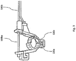
- the actuator 100a may be a deformable ring able to enclose a finger or a wrist of the user near an articular joint.
- the at least one transmission mechanical element 100b may be a Bowden cable comprising internally a tie-rod 100ba.
- the at least one force sensor 100c may be a piezoresistive force sensor placed in an inner portion of the actuator 100a in correspondence with the articular joint.
- the actuator 100a and the support structure 100d may have adjustable dimensions.
- the actuator 100a may have dimensions able to be adjusted by applying half-rings of variable size, that is, semi-cylindrical elements fixed together at a respective end, as shown in figure 3 .
- the actuator 100a may be made by means of a deformable elastic structure, a soft actuator, pneumatically powered through a pneumatic subsystem, i.e. through compressed air delivered by the electric air compressor, not shown in the figure.
- the support structure 100d may have dimensions adjustable by means of the variable positioning of the actuator 100a over said support structure 100d through clamped clamp joints.
- the possibility of adjusting the dimensions of the support structure 100d allows to adapt the biomechatronic device 100 to the different anatomical conformations of several users.
- the elasticity of the actuators 100a used for applying the mechanical nociceptive stimuli to the articular joints of the fingers of the user, in the particular case of the wearable element 200 applied to a hand, allows to use a single-effect actuator 100a, specifically a pneumatic muscle actuator.
- the initial position of the biomechatronic device 100 is reacquired, following the active phase of pneumatic compression, thanks to the elastic return ensured by the deformable structure of the actuators 100a.
- the biomechatronic device 100 allows to reproduce the characteristics of multi-channel and distributed measurement, typical of the manual procedure performed by rheumatologists.
- the biomechatronic device 100 comprises an electronic control unit 101, schematized in Figure 1 , connected to the wearable element 200 and to the electric air compressor, comprising the monitoring and control module able to manage the mechanical nociceptive stimuli and the entire biomechatronic device 100.
- the wearable element 200 comprises at least one actuator 100a for each finger of a user's hand, each actuator 100a being associable with an independent stimulation channel, i.e. an articular joint, with trends and intensity values of the force applied able to be modulated, independently for each actuator 100a, or also in a coordinated manner on different joints.
- an independent stimulation channel i.e. an articular joint
- each finger of a user's hand wears a pair of actuators 100a, connected to a support rod, so that the wearable element 200 comprises ten actuators 100a which apply the forces related to the mechanical nociceptive stimuli, the intensities of which are regulated by the monitoring and control module.
- Each support rod is connected to a support plate, part of the support structure 100d and placed on the back of the user's hand.
- the biomechatronic device 100 may comprise also an actuator 100a, able to be positioned in correspondence with the wrist of the user, that applies a mechanical nociceptive stimulus similar to that of the actuator 100a applied to a finger of the same user.
- the actuator 100a may be configured to apply to an articular joint of the user a mechanical nociceptive stimulus in terms of a force that increases linearly over time or, secondarily, that can be modulated according to a trend programmable from time to time on the basis of specific needs concerning the diagnosis of pathologies.
- the monitoring and control module for example a software module including routines for programming and scheduling the mechanical nociceptive stimuli, that includes also a management firmware able to manage the electronics of the biomechatronic device 100, may comprise also a safety subsystem able to reduce the force applied by the actuator 100a, i.e. reducing the mechanical nociceptive stimuli applied, in case of absence of the power supply of the biomechatronic device 100, or in case the mechanical nociceptive stimuli, related to the force applied to each articular joint and detected through the force sensors 100c, exceeds a safety threshold value suitably calibrated on the biomechatronic device 100.
- a safety subsystem able to reduce the force applied by the actuator 100a, i.e. reducing the mechanical nociceptive stimuli applied, in case of absence of the power supply of the biomechatronic device 100, or in case the mechanical nociceptive stimuli, related to the force applied to each articular joint and detected through the force sensors 100c, exceeds a safety threshold value suit
- the configuration of the monitoring and control module includes, in particular, the programming of the sequence of the multi-channel mechanical nociceptive stimuli, and the real-time visualization of the diagnostic parameters, said parameters being an output of the biomechatronic device 100.
- Such configuration functions are supplied to healthcare professionals through an HMI (Human Machine Interface) that resides on web pages preloaded on the electronic control unit 101.
- HMI Human Machine Interface
- the visualization of the operating parameters and the configuration of the biomechatronic device 100 for the automated diagnosis of rheumatic diseases, through the HMI interface allow the healthcare professionals to operate comfortably through a user-friendly computer tool, as well as to view any on-screen alerts concerning failures of the biomechatronic device 100.
- the aforementioned safety subsystem included in the monitoring and control module is able to interrupt the application of the compression force applied to a specific articular joint in the event of a power failure, or in the event that the applied force exceeds a predetermined threshold value.
- the safety subsystem ensures the safety of the user in case of sudden power failure, or in case of exceeding the safety threshold of the maximum force applied to the single articular joints, avoiding the persistence of the pneumatic stimuli performed by the actuators 100a, and their releasing form the joints under diagnostic investigation.
- the electronic control unit 101 may comprise a wireless module able to connect the biomechatronic device 100 to a data transmission network.
- the wireless module for example a Bluetooth LE module, allows to manage the monitoring and control module through a specific 'app' installed on a smartphone or tablet 103 supplied to healthcare professionals and/or bioengineers.
- the electronic control unit 101 may comprise a wired or wireless network module, for example a Wi-Fi or a Ethernet port.
- the use of the wired or wireless network module allows to send to a local or cloud server 104 data detected by the biomechatronic device 100, in particular the applied mechanical nociceptive stimuli, their instantaneous value upon activation of the button 102, i.e. in correspondence with the reaching of the pain threshold of the user, date and time of the measurement and the data associated with the user on whom the measurement is being carried out.
- the electronic control unit 101 may comprise a programmable embedded electronic control board, for example an iOS PCB, a Raspberry PI or another embedded mini PC based on a microcontroller unit.
- a programmable embedded electronic control board for example an iOS PCB, a Raspberry PI or another embedded mini PC based on a microcontroller unit.
- a further advantage of the biomechatronic device 100 is that, by means of the Wi-Fi or Ethernet network port, said biomechatronic device 100 can be placed into a network, either local or remote, useful for integrating it into a telemedicine service.
- the sharing of an electronic health record preferably residing on the local or cloud server 104, allows to effectively follow the temporal evolution of rheumatic disease for the individual user.
- the pain threshold is one of the parameters on which the assessment of the severity, together with the estimate of the corresponding evolution, of rheumatoid arthritis, is based.
- the current pain threshold assessment protocol in rheumatic patients lacks objectivity, since it depends on the individual perception and the close dependence on the specific health professional who performs the diagnostic tests.
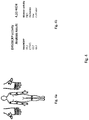
- the classification of the level of severity of rheumatic diseases is carried out by reporting on an anatomical map, in the positions corresponding to any single articular joint of the user/patient, manually stimulated by the health professionals, specifically the rheumatologists, the levels of perception of pain concerning any aforementioned joint.
- the intensity of pain is reported to the rheumatologist by the patient using a numerical value included in a scale, the VAS (Visual Analogic Scale), whose values are comprised between 0 and 100.
- VAS Visual Analogic Scale
- the algorithm developed by the Applicant running like other software routines included in the monitoring and control module in the electronic control unit 101, allows the automatic assessment of the severity of the rheumatic pathology. All this is achieved by aggregating, in a single index, the evaluation of the severity of the rheumatic disease, starting from the individual pain threshold measures resulting from the mechanical nociceptive force applied and measured on the single articular joints by means of the biomechatronic device 100.
- the biomechatronic device 100 allows an estimate of the severity of the disease as an output of the algorithm based on the measurements of nociceptive thresholds obtained automatically and in a distributed way by the individual channels, i.e. each single actuator 100a and each single force sensor 100c, that convey to the electronic control unit 101 the intensity of the mechanical nociceptive stimuli applied to the articular joints.
- the user reports the sensation of pain by mechanically acting on the button 102 connected to the electronic control unit 101, which acquires, by sampling and saving it, the intensity of the corresponding mechanical nociceptive stimulus by means of the force sensors 100c.
- the biomechatronic device 100 ensures, in an automatic way and according to the specifications of a software logic executed by the embedded electronic control board, the sequentially programmed generation and application of mechanical nociceptive stimuli on several articular joints of the user, the acquisition of pain thresholds related to such stimuli, and the evaluation of the severity index of a related rheumatic disease.
- the biomechatronic device 100 allows to automate the diagnostic protocol in a multi-channel and objective mode, regardless of the operating modes of the specific rheumatologist.
- the method of use of the biomechatronic device 100 allows to perform measurements without the intervention of the user, except for the pressure of the button, since all the steps concerning such measurements are actively carried out by means of the hardware and the logics of the biomechatronic device 100.
- the biomechatronic device for automated diagnosis of rheumatic diseases allows the reconstruction of the anatomical map of the intensity levels of the pain threshold concerning the articular joints of the user.
- biomechatronic device for automated diagnosis of rheumatic diseases allows to keep in the desired anatomical positions, i.e. the articular joints, the actuators and the sensors used to automate the measurement and ensure that the anatomical points, displayed on the anatomical map related to the pain intensity, match the actual positions on the articular joints of the patient, with the necessary characteristics of mechanical stability and precision of the stimulus and of the measurement.
- biomechatronic device for automated diagnosis of rheumatic diseases is that it ensures an objective benchmark for assessing the pain threshold and estimating the severity of the disease, remedying the lack of repeatability of the diagnostic protocols from which the known technical solutions suffer.
- a further advantage of the biomechatronic device for automated diagnosis of rheumatic diseases according to the disclosure is that its use is able to be applied to scientific research, to experimental and clinical treatments of rheumatic diseases, to the pain treatment, to the rehabilitation and to the formulation of analgesic drugs.
- biomechatronic device for automated diagnosis of rheumatic diseases is compatible with the diagnosis that makes use of the functional MRI, a known biomedical imaging technique useful for evaluating the functionality of an organ or apparatus.
- a further advantage of the biomechatronic device for automated diagnosis of rheumatic diseases according to the disclosure is that it is safe.
- biomechatronic device for automated diagnosis of rheumatic diseases is easy to use.
- biomechatronic device for automated diagnosis of rheumatic diseases is inexpensive and involves a reduced complexity concerning the prototyping and industrialization phases.
Landscapes
- Health & Medical Sciences (AREA)
- Life Sciences & Earth Sciences (AREA)
- Heart & Thoracic Surgery (AREA)
- Surgery (AREA)
- Physics & Mathematics (AREA)
- Veterinary Medicine (AREA)
- Biophysics (AREA)
- Pathology (AREA)
- Engineering & Computer Science (AREA)
- Biomedical Technology (AREA)
- Public Health (AREA)
- Medical Informatics (AREA)
- Molecular Biology (AREA)
- General Health & Medical Sciences (AREA)
- Animal Behavior & Ethology (AREA)
- Psychiatry (AREA)
- Hospice & Palliative Care (AREA)
- Pain & Pain Management (AREA)
- Dentistry (AREA)
- Oral & Maxillofacial Surgery (AREA)
- Orthopedic Medicine & Surgery (AREA)
- Rheumatology (AREA)
- Measurement Of The Respiration, Hearing Ability, Form, And Blood Characteristics Of Living Organisms (AREA)
Claims (12)
- Dispositif biomécatronique (100) pour le diagnostic automatisé de maladies rhumatismales, comprenant- au moins un élément portable (200) comprenant au moins un actionneur (100a) configuré pour appliquer des stimuli mécaniques nociceptifs à au moins une articulation d'un utilisateur, et au moins un capteur de force (100c) ;- un compresseur d'air électrique capable de générer une force par l'intermédiaire d'un entraînement pneumatique de l'au moins un actionneur (100a);- au moins un élément mécanique de transmission (100b) relié à l'au moins un actionneur (100a) et configuré pour transmettre la force générée par le compresseur d'air électrique audit au moins un actionneur (100a), ladite force correspondant aux stimuli mécaniques nociceptifs appliqués à au moins une articulation de l'utilisateur ;- un bouton (102) ;- une unité de commande électronique (101) connectée à l'au moins un élément portable (200), au bouton (102) et au compresseur d'air électrique ;dans lequel :1) le au moins un capteur de force (100c) est capable de détecter l'intensité des stimuli mécaniques nociceptifs appliqués par ledit au moins un actionneur (100a),2) le bouton (102) est configuré pour être actionné par l'utilisateur et est capable d'interrompre l'application des stimuli mécaniques nociceptifs et de signaler l'atteinte du seuil de douleur, et3)l'unité de commande électronique (101) comprend un module de surveillance et de commande capable de gérer les stimuli mécaniques nociceptifs appliqués par le dispositif biomécatronique (100), ladite unité de commande électronique (101) étant capable d'acquérir la valeur instantanée des stimuli mécaniques nociceptifs détectés par le au moins un capteur de force (100c) lorsque le bouton (102) est actionné par l'utilisateur.
- Dispositif biomécatronique (100) selon la revendication 1, caractérisé en ce qu'il comprend une structure de support (100d) configurée pour loger le au moins un actionneur (100a), le au moins un élément mécanique de transmission (100b) et le au moins un capteur de force (100c), ladite structure de support (100d) étant capable de positionner l'élément portable (200) près d'au moins une articulation de l'utilisateur.
- Dispositif biomécatronique (100) selon la revendication 1, caractérisé en ce que le au moins un actionneur (100a) est au moins un anneau déformable configuré pour entourer un doigt ou un poignet de l'utilisateur près d'une articulation.
- Dispositif biomécatronique (100) selon la revendication 1, caractérisé en ce que le au moins un élément mécanique de transmission (100b) est un câble Bowden comprenant en interne une barre de liaison (100ba).
- Dispositif biomécatronique (100) selon la revendication 1, caractérisé en ce que le au moins un capteur de force (100c) est un capteur de force piézorésistif placé dans une partie interne du au moins un actionneur (100a) en correspondance avec l'articulation.
- Dispositif biomécatronique (100) selon la revendication 1, caractérisé en ce que le au moins un actionneur (100a) a des dimensions réglables en appliquant des demi-cylindres ayant une taille variable.
- Dispositif biomécatronique (100) selon la revendication 1, caractérisé en ce que le au moins un actionneur (100a) est réalisé au moyen d'une structure élastique déformable alimentée par un sous-système pneumatique.
- Dispositif biomécatronique (100) selon la revendication 1, caractérisé en ce que la structure de support (100d) a des dimensions pouvant être ajustées au moyen du positionnement variable de l'au moins un actionneur (100a) sur ladite structure de support (100d) par l'intermédiaire de joints serrés.
- Dispositif biomécatronique (100) selon l'une des revendications précédentes, caractérisé en ce que ladite unité de commande électronique (101) comprend un module de surveillance et de commande comprenant un sous-système de sécurité capable de réduire la force appliquée en réduisant les stimuli mécaniques nociceptifs en cas d'absence de l'alimentation électrique du dispositif biomécatronique (100)ou dans le cas où les stimuli mécaniques nociceptifs, liés à la force appliquée à chaque articulation et détectés au moyen des capteurs de force (100c), dépassent une valeur limite de sécurité, ladite valeur limite de sécurité étant calibrée sur le dispositif biomécatronique (100).
- Dispositif biomécatronique (100) selon la revendication 1, caractérisé en ce que l'unité de commande électronique (101) comprend un module sans fil capable de connecter le dispositif biomécatronique (100) à un réseau de transmission de données.
- Dispositif biomécatronique (100) selon la revendication 1, caractérisé en ce que l'unité de commande électronique (101) comprend une carte de commande électronique intégrée programmable.
- Procédé d'utilisation du dispositif biomécatronique (100) selon l'une des revendications précédentes, caractérisé en ce qu'il comprend les étapes consistant à :- appliquer au moins un élément portable (200) compris dans le dispositif biomécatronique (100) à une partie du corps d'un utilisateur, ledit élément portable (200) comprenant des actionneurs capables d'appliquer des stimuli mécaniques nociceptifs à au moins une articulation de l'utilisateur, et lesdits capteurs de force étant capables de détecter l'intensité des stimuli mécaniques nociceptifs ;- programmer et gérer une séquence de stimuli mécaniques nociceptifs au moyen d'un module de surveillance et de commande inclus dans une unité de commande électronique connectée à l'élément portable (200), à un compresseur d'air électrique configuré pour entraîner par voie pneumatique les actionneurs au moyen d'au moins un élément mécanique de transmission connecté à l'élément portable (200), et à un bouton ;- montrer en temps réel et sur une carte anatomique présentant les articulations de l'utilisateur les intensités des stimuli mécaniques nociceptifs, échantillonnés et acquis par l'unité de commande électronique à un instant correspondant au moment de la pression appliquée par l'utilisateur sur le bouton.
Applications Claiming Priority (1)
| Application Number | Priority Date | Filing Date | Title |
|---|---|---|---|
| IT102019000024202A IT201900024202A1 (it) | 2019-12-17 | 2019-12-17 | Dispositivo biomeccatronico per diagnosi automatizzata di patologie reumatiche |
Publications (2)
| Publication Number | Publication Date |
|---|---|
| EP3847952A1 EP3847952A1 (fr) | 2021-07-14 |
| EP3847952B1 true EP3847952B1 (fr) | 2022-08-10 |
Family
ID=70155086
Family Applications (1)
| Application Number | Title | Priority Date | Filing Date |
|---|---|---|---|
| EP20214445.7A Active EP3847952B1 (fr) | 2019-12-17 | 2020-12-16 | Dispositif biomécatronique pour le diagnostic automatisé des maladies rhumatismales |
Country Status (2)
| Country | Link |
|---|---|
| EP (1) | EP3847952B1 (fr) |
| IT (1) | IT201900024202A1 (fr) |
Family Cites Families (7)
| Publication number | Priority date | Publication date | Assignee | Title |
|---|---|---|---|---|
| ES2652026T3 (es) * | 2006-09-01 | 2018-01-31 | Bioservo Technologies Ab | Guante de refuerzo |
| WO2010033055A1 (fr) | 2008-09-17 | 2010-03-25 | Handmedic Hb | Système d'application sur la main de stimuli vibratoires sélectifs commandés |
| WO2010064200A1 (fr) * | 2008-12-05 | 2010-06-10 | Koninklijke Philips Electronics N.V. | Procédé et dispositif pour l'examen optique de l'état des articulations |
| CA2794193C (fr) * | 2010-03-23 | 2017-08-22 | Idrogenet S.R.L. | Dispositif de reeducation de la main |
| CN208876564U (zh) * | 2017-09-30 | 2019-05-21 | 朱文 | 一种关节肿痛手握力参数的检测传输装置 |
| KR102082280B1 (ko) | 2018-03-22 | 2020-02-27 | (주)대성마리프 | 글러브 타입 수관절 치료장치 |
| CN108392375A (zh) | 2018-04-19 | 2018-08-14 | 郑州大学 | 一种气动软体功能康复手套 |
-
2019
- 2019-12-17 IT IT102019000024202A patent/IT201900024202A1/it unknown
-
2020
- 2020-12-16 EP EP20214445.7A patent/EP3847952B1/fr active Active
Also Published As
| Publication number | Publication date |
|---|---|
| IT201900024202A1 (it) | 2021-06-17 |
| EP3847952A1 (fr) | 2021-07-14 |
Similar Documents
| Publication | Publication Date | Title |
|---|---|---|
| US11065142B2 (en) | Orthopedic devices and systems integrated with controlling devices | |
| Sardini et al. | Wireless wearable T-shirt for posture monitoring during rehabilitation exercises | |
| US8568312B2 (en) | Electro diagnostic functional assessment unit (EFA-3) | |
| US9433478B2 (en) | Orthodontic apparatus | |
| US9307906B2 (en) | Multimodal automated sensory testing system | |
| CN106413532B (zh) | 康复系统和方法 | |
| KR20140037938A (ko) | 손상된 사지를 재활 치료하기 위한 장치 및 방법 | |
| WO2017049104A1 (fr) | Quantification de force lors du massage des tissus mous pour la recherche et l'utilisation clinique | |
| CA3012690A1 (fr) | Dispositif et systeme pour mesurer et evaluer les caracteristiques contractiles de muscles superficiels | |
| CZ2018559A3 (cs) | Zařízení pro měření svalové síly a způsob testování svalového výkonu sportovců | |
| EP3938025B1 (fr) | Dispositif intégré pour l'électromyographie et l'électrothérapie | |
| JP2015526163A (ja) | 患者の少なくとも一の筋肉についての情報の提供に用いる装置 | |
| CN213250102U (zh) | 一种步态采集及神经肌肉电刺激动力式踝足矫形器 | |
| WO2015188867A1 (fr) | Analyse et évaluation de la qualité de mouvements corporels | |
| CN113520787A (zh) | 用于全膝关节置换围术期的交互式穿戴设备 | |
| EP3847952B1 (fr) | Dispositif biomécatronique pour le diagnostic automatisé des maladies rhumatismales | |
| JP5544651B2 (ja) | 筋骨格系機構システム | |
| JP6145663B2 (ja) | 生体信号計測システム、および生体信号計測方法 | |
| WO2019206954A1 (fr) | Système multi-capteur de diagnostic thérapeutique destiné à surveiller l'entraînement orthopédique et la performance sportive | |
| Surya et al. | Robotic exoskeleton for rehabilitation of TMD via assisted motion of jaw | |
| RU86866U1 (ru) | Устройство для исследования инструментальных рефлексов | |
| Chen et al. | Design of the workstation for hand rehabilitation based on data glove | |
| CN113181021A (zh) | 一种基于物联网技术的智能压力治疗仪系统 | |
| EP3677184A1 (fr) | Système de support de contrainte | |
| SK3092025U1 (sk) | Monitorovací systém konzervatívnej liečby pectus excavatum |
Legal Events
| Date | Code | Title | Description |
|---|---|---|---|
| PUAI | Public reference made under article 153(3) epc to a published international application that has entered the european phase |
Free format text: ORIGINAL CODE: 0009012 |
|
| STAA | Information on the status of an ep patent application or granted ep patent |
Free format text: STATUS: THE APPLICATION HAS BEEN PUBLISHED |
|
| AK | Designated contracting states |
Kind code of ref document: A1 Designated state(s): AL AT BE BG CH CY CZ DE DK EE ES FI FR GB GR HR HU IE IS IT LI LT LU LV MC MK MT NL NO PL PT RO RS SE SI SK SM TR |
|
| STAA | Information on the status of an ep patent application or granted ep patent |
Free format text: STATUS: REQUEST FOR EXAMINATION WAS MADE |
|
| 17P | Request for examination filed |
Effective date: 20211210 |
|
| RBV | Designated contracting states (corrected) |
Designated state(s): AL AT BE BG CH CY CZ DE DK EE ES FI FR GB GR HR HU IE IS IT LI LT LU LV MC MK MT NL NO PL PT RO RS SE SI SK SM TR |
|
| GRAP | Despatch of communication of intention to grant a patent |
Free format text: ORIGINAL CODE: EPIDOSNIGR1 |
|
| STAA | Information on the status of an ep patent application or granted ep patent |
Free format text: STATUS: GRANT OF PATENT IS INTENDED |
|
| INTG | Intention to grant announced |
Effective date: 20220511 |
|
| RIN1 | Information on inventor provided before grant (corrected) |
Inventor name: GREMBIALE, ROSA DANIELA Inventor name: COSENTINO, CARLO Inventor name: RANDAZZINI, LUIGI Inventor name: MEROLA, ALESSIO |
|
| GRAS | Grant fee paid |
Free format text: ORIGINAL CODE: EPIDOSNIGR3 |
|
| GRAA | (expected) grant |
Free format text: ORIGINAL CODE: 0009210 |
|
| STAA | Information on the status of an ep patent application or granted ep patent |
Free format text: STATUS: THE PATENT HAS BEEN GRANTED |
|
| AK | Designated contracting states |
Kind code of ref document: B1 Designated state(s): AL AT BE BG CH CY CZ DE DK EE ES FI FR GB GR HR HU IE IS IT LI LT LU LV MC MK MT NL NO PL PT RO RS SE SI SK SM TR |
|
| REG | Reference to a national code |
Ref country code: AT Ref legal event code: REF Ref document number: 1509902 Country of ref document: AT Kind code of ref document: T Effective date: 20220815 Ref country code: CH Ref legal event code: EP |
|
| REG | Reference to a national code |
Ref country code: IE Ref legal event code: FG4D |
|
| REG | Reference to a national code |
Ref country code: DE Ref legal event code: R096 Ref document number: 602020004469 Country of ref document: DE |
|
| REG | Reference to a national code |
Ref country code: NL Ref legal event code: MP Effective date: 20220810 |
|
| REG | Reference to a national code |
Ref country code: LT Ref legal event code: MG9D |
|
| PG25 | Lapsed in a contracting state [announced via postgrant information from national office to epo] |
Ref country code: SE Free format text: LAPSE BECAUSE OF FAILURE TO SUBMIT A TRANSLATION OF THE DESCRIPTION OR TO PAY THE FEE WITHIN THE PRESCRIBED TIME-LIMIT Effective date: 20220810 Ref country code: RS Free format text: LAPSE BECAUSE OF FAILURE TO SUBMIT A TRANSLATION OF THE DESCRIPTION OR TO PAY THE FEE WITHIN THE PRESCRIBED TIME-LIMIT Effective date: 20220810 Ref country code: PT Free format text: LAPSE BECAUSE OF FAILURE TO SUBMIT A TRANSLATION OF THE DESCRIPTION OR TO PAY THE FEE WITHIN THE PRESCRIBED TIME-LIMIT Effective date: 20221212 Ref country code: NO Free format text: LAPSE BECAUSE OF FAILURE TO SUBMIT A TRANSLATION OF THE DESCRIPTION OR TO PAY THE FEE WITHIN THE PRESCRIBED TIME-LIMIT Effective date: 20221110 Ref country code: NL Free format text: LAPSE BECAUSE OF FAILURE TO SUBMIT A TRANSLATION OF THE DESCRIPTION OR TO PAY THE FEE WITHIN THE PRESCRIBED TIME-LIMIT Effective date: 20220810 Ref country code: LV Free format text: LAPSE BECAUSE OF FAILURE TO SUBMIT A TRANSLATION OF THE DESCRIPTION OR TO PAY THE FEE WITHIN THE PRESCRIBED TIME-LIMIT Effective date: 20220810 Ref country code: LT Free format text: LAPSE BECAUSE OF FAILURE TO SUBMIT A TRANSLATION OF THE DESCRIPTION OR TO PAY THE FEE WITHIN THE PRESCRIBED TIME-LIMIT Effective date: 20220810 Ref country code: FI Free format text: LAPSE BECAUSE OF FAILURE TO SUBMIT A TRANSLATION OF THE DESCRIPTION OR TO PAY THE FEE WITHIN THE PRESCRIBED TIME-LIMIT Effective date: 20220810 |
|
| REG | Reference to a national code |
Ref country code: AT Ref legal event code: MK05 Ref document number: 1509902 Country of ref document: AT Kind code of ref document: T Effective date: 20220810 |
|
| PG25 | Lapsed in a contracting state [announced via postgrant information from national office to epo] |
Ref country code: PL Free format text: LAPSE BECAUSE OF FAILURE TO SUBMIT A TRANSLATION OF THE DESCRIPTION OR TO PAY THE FEE WITHIN THE PRESCRIBED TIME-LIMIT Effective date: 20220810 Ref country code: IS Free format text: LAPSE BECAUSE OF FAILURE TO SUBMIT A TRANSLATION OF THE DESCRIPTION OR TO PAY THE FEE WITHIN THE PRESCRIBED TIME-LIMIT Effective date: 20221210 Ref country code: HR Free format text: LAPSE BECAUSE OF FAILURE TO SUBMIT A TRANSLATION OF THE DESCRIPTION OR TO PAY THE FEE WITHIN THE PRESCRIBED TIME-LIMIT Effective date: 20220810 Ref country code: GR Free format text: LAPSE BECAUSE OF FAILURE TO SUBMIT A TRANSLATION OF THE DESCRIPTION OR TO PAY THE FEE WITHIN THE PRESCRIBED TIME-LIMIT Effective date: 20221111 |
|
| PG25 | Lapsed in a contracting state [announced via postgrant information from national office to epo] |
Ref country code: SM Free format text: LAPSE BECAUSE OF FAILURE TO SUBMIT A TRANSLATION OF THE DESCRIPTION OR TO PAY THE FEE WITHIN THE PRESCRIBED TIME-LIMIT Effective date: 20220810 Ref country code: RO Free format text: LAPSE BECAUSE OF FAILURE TO SUBMIT A TRANSLATION OF THE DESCRIPTION OR TO PAY THE FEE WITHIN THE PRESCRIBED TIME-LIMIT Effective date: 20220810 Ref country code: ES Free format text: LAPSE BECAUSE OF FAILURE TO SUBMIT A TRANSLATION OF THE DESCRIPTION OR TO PAY THE FEE WITHIN THE PRESCRIBED TIME-LIMIT Effective date: 20220810 Ref country code: DK Free format text: LAPSE BECAUSE OF FAILURE TO SUBMIT A TRANSLATION OF THE DESCRIPTION OR TO PAY THE FEE WITHIN THE PRESCRIBED TIME-LIMIT Effective date: 20220810 Ref country code: CZ Free format text: LAPSE BECAUSE OF FAILURE TO SUBMIT A TRANSLATION OF THE DESCRIPTION OR TO PAY THE FEE WITHIN THE PRESCRIBED TIME-LIMIT Effective date: 20220810 Ref country code: AT Free format text: LAPSE BECAUSE OF FAILURE TO SUBMIT A TRANSLATION OF THE DESCRIPTION OR TO PAY THE FEE WITHIN THE PRESCRIBED TIME-LIMIT Effective date: 20220810 |
|
| REG | Reference to a national code |
Ref country code: DE Ref legal event code: R097 Ref document number: 602020004469 Country of ref document: DE |
|
| PG25 | Lapsed in a contracting state [announced via postgrant information from national office to epo] |
Ref country code: SK Free format text: LAPSE BECAUSE OF FAILURE TO SUBMIT A TRANSLATION OF THE DESCRIPTION OR TO PAY THE FEE WITHIN THE PRESCRIBED TIME-LIMIT Effective date: 20220810 Ref country code: EE Free format text: LAPSE BECAUSE OF FAILURE TO SUBMIT A TRANSLATION OF THE DESCRIPTION OR TO PAY THE FEE WITHIN THE PRESCRIBED TIME-LIMIT Effective date: 20220810 |
|
| PLBE | No opposition filed within time limit |
Free format text: ORIGINAL CODE: 0009261 |
|
| STAA | Information on the status of an ep patent application or granted ep patent |
Free format text: STATUS: NO OPPOSITION FILED WITHIN TIME LIMIT |
|
| PG25 | Lapsed in a contracting state [announced via postgrant information from national office to epo] |
Ref country code: AL Free format text: LAPSE BECAUSE OF FAILURE TO SUBMIT A TRANSLATION OF THE DESCRIPTION OR TO PAY THE FEE WITHIN THE PRESCRIBED TIME-LIMIT Effective date: 20220810 |
|
| 26N | No opposition filed |
Effective date: 20230511 |
|
| REG | Reference to a national code |
Ref country code: BE Ref legal event code: MM Effective date: 20221231 |
|
| PG25 | Lapsed in a contracting state [announced via postgrant information from national office to epo] |
Ref country code: SI Free format text: LAPSE BECAUSE OF FAILURE TO SUBMIT A TRANSLATION OF THE DESCRIPTION OR TO PAY THE FEE WITHIN THE PRESCRIBED TIME-LIMIT Effective date: 20220810 Ref country code: LU Free format text: LAPSE BECAUSE OF NON-PAYMENT OF DUE FEES Effective date: 20221216 |
|
| PG25 | Lapsed in a contracting state [announced via postgrant information from national office to epo] |
Ref country code: IE Free format text: LAPSE BECAUSE OF NON-PAYMENT OF DUE FEES Effective date: 20221216 |
|
| PG25 | Lapsed in a contracting state [announced via postgrant information from national office to epo] |
Ref country code: BE Free format text: LAPSE BECAUSE OF NON-PAYMENT OF DUE FEES Effective date: 20221231 |
|
| P01 | Opt-out of the competence of the unified patent court (upc) registered |
Effective date: 20231208 |
|
| PG25 | Lapsed in a contracting state [announced via postgrant information from national office to epo] |
Ref country code: CY Free format text: LAPSE BECAUSE OF FAILURE TO SUBMIT A TRANSLATION OF THE DESCRIPTION OR TO PAY THE FEE WITHIN THE PRESCRIBED TIME-LIMIT Effective date: 20220810 |
|
| PG25 | Lapsed in a contracting state [announced via postgrant information from national office to epo] |
Ref country code: MK Free format text: LAPSE BECAUSE OF FAILURE TO SUBMIT A TRANSLATION OF THE DESCRIPTION OR TO PAY THE FEE WITHIN THE PRESCRIBED TIME-LIMIT Effective date: 20220810 |
|
| PG25 | Lapsed in a contracting state [announced via postgrant information from national office to epo] |
Ref country code: MC Free format text: LAPSE BECAUSE OF FAILURE TO SUBMIT A TRANSLATION OF THE DESCRIPTION OR TO PAY THE FEE WITHIN THE PRESCRIBED TIME-LIMIT Effective date: 20220810 |
|
| PG25 | Lapsed in a contracting state [announced via postgrant information from national office to epo] |
Ref country code: TR Free format text: LAPSE BECAUSE OF FAILURE TO SUBMIT A TRANSLATION OF THE DESCRIPTION OR TO PAY THE FEE WITHIN THE PRESCRIBED TIME-LIMIT Effective date: 20220810 Ref country code: MC Free format text: LAPSE BECAUSE OF FAILURE TO SUBMIT A TRANSLATION OF THE DESCRIPTION OR TO PAY THE FEE WITHIN THE PRESCRIBED TIME-LIMIT Effective date: 20220810 |
|
| PG25 | Lapsed in a contracting state [announced via postgrant information from national office to epo] |
Ref country code: BG Free format text: LAPSE BECAUSE OF FAILURE TO SUBMIT A TRANSLATION OF THE DESCRIPTION OR TO PAY THE FEE WITHIN THE PRESCRIBED TIME-LIMIT Effective date: 20220810 |
|
| REG | Reference to a national code |
Ref country code: CH Ref legal event code: PL |
|
| PG25 | Lapsed in a contracting state [announced via postgrant information from national office to epo] |
Ref country code: MT Free format text: LAPSE BECAUSE OF FAILURE TO SUBMIT A TRANSLATION OF THE DESCRIPTION OR TO PAY THE FEE WITHIN THE PRESCRIBED TIME-LIMIT Effective date: 20220810 |
|
| PG25 | Lapsed in a contracting state [announced via postgrant information from national office to epo] |
Ref country code: CH Free format text: LAPSE BECAUSE OF NON-PAYMENT OF DUE FEES Effective date: 20231231 |
|
| PG25 | Lapsed in a contracting state [announced via postgrant information from national office to epo] |
Ref country code: CH Free format text: LAPSE BECAUSE OF NON-PAYMENT OF DUE FEES Effective date: 20231231 |
|
| PGFP | Annual fee paid to national office [announced via postgrant information from national office to epo] |
Ref country code: GB Payment date: 20241227 Year of fee payment: 5 |
|
| PGFP | Annual fee paid to national office [announced via postgrant information from national office to epo] |
Ref country code: FR Payment date: 20241224 Year of fee payment: 5 |
|
| PGFP | Annual fee paid to national office [announced via postgrant information from national office to epo] |
Ref country code: IT Payment date: 20241218 Year of fee payment: 5 |
|
| PGFP | Annual fee paid to national office [announced via postgrant information from national office to epo] |
Ref country code: DE Payment date: 20241230 Year of fee payment: 5 |
|
| PG25 | Lapsed in a contracting state [announced via postgrant information from national office to epo] |
Ref country code: HU Free format text: LAPSE BECAUSE OF FAILURE TO SUBMIT A TRANSLATION OF THE DESCRIPTION OR TO PAY THE FEE WITHIN THE PRESCRIBED TIME-LIMIT; INVALID AB INITIO Effective date: 20201216 |