EP3848183B1 - Système d'impression 3d pour fabriquer des vaisseaux sanguins artificiels, et procédé de fabrication de vaisseaux sanguins artificiels au moyen de celui-ci - Google Patents
Système d'impression 3d pour fabriquer des vaisseaux sanguins artificiels, et procédé de fabrication de vaisseaux sanguins artificiels au moyen de celui-ci Download PDFInfo
- Publication number
- EP3848183B1 EP3848183B1 EP19929182.4A EP19929182A EP3848183B1 EP 3848183 B1 EP3848183 B1 EP 3848183B1 EP 19929182 A EP19929182 A EP 19929182A EP 3848183 B1 EP3848183 B1 EP 3848183B1
- Authority
- EP
- European Patent Office
- Prior art keywords
- support
- head
- sections
- hydrogel
- divided
- Prior art date
- Legal status (The legal status is an assumption and is not a legal conclusion. Google has not performed a legal analysis and makes no representation as to the accuracy of the status listed.)
- Active
Links
Images








Classifications
-
- B—PERFORMING OPERATIONS; TRANSPORTING
- B29—WORKING OF PLASTICS; WORKING OF SUBSTANCES IN A PLASTIC STATE IN GENERAL
- B29C—SHAPING OR JOINING OF PLASTICS; SHAPING OF MATERIAL IN A PLASTIC STATE, NOT OTHERWISE PROVIDED FOR; AFTER-TREATMENT OF THE SHAPED PRODUCTS, e.g. REPAIRING
- B29C64/00—Additive manufacturing, i.e. manufacturing of three-dimensional [3D] objects by additive deposition, additive agglomeration or additive layering, e.g. by 3D printing, stereolithography or selective laser sintering
- B29C64/40—Structures for supporting 3D objects during manufacture and intended to be sacrificed after completion thereof
-
- B—PERFORMING OPERATIONS; TRANSPORTING
- B29—WORKING OF PLASTICS; WORKING OF SUBSTANCES IN A PLASTIC STATE IN GENERAL
- B29C—SHAPING OR JOINING OF PLASTICS; SHAPING OF MATERIAL IN A PLASTIC STATE, NOT OTHERWISE PROVIDED FOR; AFTER-TREATMENT OF THE SHAPED PRODUCTS, e.g. REPAIRING
- B29C64/00—Additive manufacturing, i.e. manufacturing of three-dimensional [3D] objects by additive deposition, additive agglomeration or additive layering, e.g. by 3D printing, stereolithography or selective laser sintering
- B29C64/20—Apparatus for additive manufacturing; Details thereof or accessories therefor
- B29C64/245—Platforms or substrates
-
- A—HUMAN NECESSITIES
- A61—MEDICAL OR VETERINARY SCIENCE; HYGIENE
- A61F—FILTERS IMPLANTABLE INTO BLOOD VESSELS; PROSTHESES; DEVICES PROVIDING PATENCY TO, OR PREVENTING COLLAPSING OF, TUBULAR STRUCTURES OF THE BODY, e.g. STENTS; ORTHOPAEDIC, NURSING OR CONTRACEPTIVE DEVICES; FOMENTATION; TREATMENT OR PROTECTION OF EYES OR EARS; BANDAGES, DRESSINGS OR ABSORBENT PADS; FIRST-AID KITS
- A61F2/00—Filters implantable into blood vessels; Prostheses, i.e. artificial substitutes or replacements for parts of the body; Appliances for connecting them with the body; Devices providing patency to, or preventing collapsing of, tubular structures of the body, e.g. stents
- A61F2/02—Prostheses implantable into the body
- A61F2/04—Hollow or tubular parts of organs, e.g. bladders, tracheae, bronchi or bile ducts
- A61F2/06—Blood vessels
-
- B—PERFORMING OPERATIONS; TRANSPORTING
- B25—HAND TOOLS; PORTABLE POWER-DRIVEN TOOLS; MANIPULATORS
- B25B—TOOLS OR BENCH DEVICES NOT OTHERWISE PROVIDED FOR, FOR FASTENING, CONNECTING, DISENGAGING, OR HOLDING
- B25B5/00—Clamps
- B25B5/06—Arrangements for positively actuating jaws
- B25B5/10—Arrangements for positively actuating jaws using screws
-
- B—PERFORMING OPERATIONS; TRANSPORTING
- B25—HAND TOOLS; PORTABLE POWER-DRIVEN TOOLS; MANIPULATORS
- B25B—TOOLS OR BENCH DEVICES NOT OTHERWISE PROVIDED FOR, FOR FASTENING, CONNECTING, DISENGAGING, OR HOLDING
- B25B5/00—Clamps
- B25B5/14—Clamps for work of special profile
- B25B5/147—Clamps for work of special profile for pipes
-
- B—PERFORMING OPERATIONS; TRANSPORTING
- B29—WORKING OF PLASTICS; WORKING OF SUBSTANCES IN A PLASTIC STATE IN GENERAL
- B29C—SHAPING OR JOINING OF PLASTICS; SHAPING OF MATERIAL IN A PLASTIC STATE, NOT OTHERWISE PROVIDED FOR; AFTER-TREATMENT OF THE SHAPED PRODUCTS, e.g. REPAIRING
- B29C64/00—Additive manufacturing, i.e. manufacturing of three-dimensional [3D] objects by additive deposition, additive agglomeration or additive layering, e.g. by 3D printing, stereolithography or selective laser sintering
- B29C64/10—Processes of additive manufacturing
- B29C64/106—Processes of additive manufacturing using only liquids or viscous materials, e.g. depositing a continuous bead of viscous material
-
- B—PERFORMING OPERATIONS; TRANSPORTING
- B29—WORKING OF PLASTICS; WORKING OF SUBSTANCES IN A PLASTIC STATE IN GENERAL
- B29C—SHAPING OR JOINING OF PLASTICS; SHAPING OF MATERIAL IN A PLASTIC STATE, NOT OTHERWISE PROVIDED FOR; AFTER-TREATMENT OF THE SHAPED PRODUCTS, e.g. REPAIRING
- B29C64/00—Additive manufacturing, i.e. manufacturing of three-dimensional [3D] objects by additive deposition, additive agglomeration or additive layering, e.g. by 3D printing, stereolithography or selective laser sintering
- B29C64/20—Apparatus for additive manufacturing; Details thereof or accessories therefor
- B29C64/205—Means for applying layers
- B29C64/209—Heads; Nozzles
-
- B—PERFORMING OPERATIONS; TRANSPORTING
- B29—WORKING OF PLASTICS; WORKING OF SUBSTANCES IN A PLASTIC STATE IN GENERAL
- B29C—SHAPING OR JOINING OF PLASTICS; SHAPING OF MATERIAL IN A PLASTIC STATE, NOT OTHERWISE PROVIDED FOR; AFTER-TREATMENT OF THE SHAPED PRODUCTS, e.g. REPAIRING
- B29C64/00—Additive manufacturing, i.e. manufacturing of three-dimensional [3D] objects by additive deposition, additive agglomeration or additive layering, e.g. by 3D printing, stereolithography or selective laser sintering
- B29C64/30—Auxiliary operations or equipment
-
- B—PERFORMING OPERATIONS; TRANSPORTING
- B33—ADDITIVE MANUFACTURING TECHNOLOGY
- B33Y—ADDITIVE MANUFACTURING, i.e. MANUFACTURING OF THREE-DIMENSIONAL [3D] OBJECTS BY ADDITIVE DEPOSITION, ADDITIVE AGGLOMERATION OR ADDITIVE LAYERING, e.g. BY 3D PRINTING, STEREOLITHOGRAPHY OR SELECTIVE LASER SINTERING
- B33Y10/00—Processes of additive manufacturing
-
- B—PERFORMING OPERATIONS; TRANSPORTING
- B33—ADDITIVE MANUFACTURING TECHNOLOGY
- B33Y—ADDITIVE MANUFACTURING, i.e. MANUFACTURING OF THREE-DIMENSIONAL [3D] OBJECTS BY ADDITIVE DEPOSITION, ADDITIVE AGGLOMERATION OR ADDITIVE LAYERING, e.g. BY 3D PRINTING, STEREOLITHOGRAPHY OR SELECTIVE LASER SINTERING
- B33Y30/00—Apparatus for additive manufacturing; Details thereof or accessories therefor
-
- B—PERFORMING OPERATIONS; TRANSPORTING
- B33—ADDITIVE MANUFACTURING TECHNOLOGY
- B33Y—ADDITIVE MANUFACTURING, i.e. MANUFACTURING OF THREE-DIMENSIONAL [3D] OBJECTS BY ADDITIVE DEPOSITION, ADDITIVE AGGLOMERATION OR ADDITIVE LAYERING, e.g. BY 3D PRINTING, STEREOLITHOGRAPHY OR SELECTIVE LASER SINTERING
- B33Y40/00—Auxiliary operations or equipment, e.g. for material handling
-
- B—PERFORMING OPERATIONS; TRANSPORTING
- B33—ADDITIVE MANUFACTURING TECHNOLOGY
- B33Y—ADDITIVE MANUFACTURING, i.e. MANUFACTURING OF THREE-DIMENSIONAL [3D] OBJECTS BY ADDITIVE DEPOSITION, ADDITIVE AGGLOMERATION OR ADDITIVE LAYERING, e.g. BY 3D PRINTING, STEREOLITHOGRAPHY OR SELECTIVE LASER SINTERING
- B33Y70/00—Materials specially adapted for additive manufacturing
-
- B—PERFORMING OPERATIONS; TRANSPORTING
- B33—ADDITIVE MANUFACTURING TECHNOLOGY
- B33Y—ADDITIVE MANUFACTURING, i.e. MANUFACTURING OF THREE-DIMENSIONAL [3D] OBJECTS BY ADDITIVE DEPOSITION, ADDITIVE AGGLOMERATION OR ADDITIVE LAYERING, e.g. BY 3D PRINTING, STEREOLITHOGRAPHY OR SELECTIVE LASER SINTERING
- B33Y80/00—Products made by additive manufacturing
-
- A—HUMAN NECESSITIES
- A61—MEDICAL OR VETERINARY SCIENCE; HYGIENE
- A61F—FILTERS IMPLANTABLE INTO BLOOD VESSELS; PROSTHESES; DEVICES PROVIDING PATENCY TO, OR PREVENTING COLLAPSING OF, TUBULAR STRUCTURES OF THE BODY, e.g. STENTS; ORTHOPAEDIC, NURSING OR CONTRACEPTIVE DEVICES; FOMENTATION; TREATMENT OR PROTECTION OF EYES OR EARS; BANDAGES, DRESSINGS OR ABSORBENT PADS; FIRST-AID KITS
- A61F2/00—Filters implantable into blood vessels; Prostheses, i.e. artificial substitutes or replacements for parts of the body; Appliances for connecting them with the body; Devices providing patency to, or preventing collapsing of, tubular structures of the body, e.g. stents
- A61F2/0077—Special surfaces of prostheses, e.g. for improving ingrowth
- A61F2002/0081—Special surfaces of prostheses, e.g. for improving ingrowth directly machined on the prosthetic surface, e.g. holes, grooves
-
- A—HUMAN NECESSITIES
- A61—MEDICAL OR VETERINARY SCIENCE; HYGIENE
- A61F—FILTERS IMPLANTABLE INTO BLOOD VESSELS; PROSTHESES; DEVICES PROVIDING PATENCY TO, OR PREVENTING COLLAPSING OF, TUBULAR STRUCTURES OF THE BODY, e.g. STENTS; ORTHOPAEDIC, NURSING OR CONTRACEPTIVE DEVICES; FOMENTATION; TREATMENT OR PROTECTION OF EYES OR EARS; BANDAGES, DRESSINGS OR ABSORBENT PADS; FIRST-AID KITS
- A61F2240/00—Manufacturing or designing of prostheses classified in groups A61F2/00 - A61F2/26 or A61F2/82 or A61F9/00 or A61F11/00 or subgroups thereof
- A61F2240/001—Designing or manufacturing processes
- A61F2240/002—Designing or making customized prostheses
-
- B—PERFORMING OPERATIONS; TRANSPORTING
- B29—WORKING OF PLASTICS; WORKING OF SUBSTANCES IN A PLASTIC STATE IN GENERAL
- B29K—INDEXING SCHEME ASSOCIATED WITH SUBCLASSES B29B, B29C OR B29D, RELATING TO MOULDING MATERIALS OR TO MATERIALS FOR MOULDS, REINFORCEMENTS, FILLERS OR PREFORMED PARTS, e.g. INSERTS
- B29K2101/00—Use of unspecified macromolecular compounds as moulding material
- B29K2101/12—Thermoplastic materials
-
- B—PERFORMING OPERATIONS; TRANSPORTING
- B29—WORKING OF PLASTICS; WORKING OF SUBSTANCES IN A PLASTIC STATE IN GENERAL
- B29K—INDEXING SCHEME ASSOCIATED WITH SUBCLASSES B29B, B29C OR B29D, RELATING TO MOULDING MATERIALS OR TO MATERIALS FOR MOULDS, REINFORCEMENTS, FILLERS OR PREFORMED PARTS, e.g. INSERTS
- B29K2105/00—Condition, form or state of moulded material or of the material to be shaped
- B29K2105/0058—Liquid or visquous
- B29K2105/0061—Gel or sol
-
- B—PERFORMING OPERATIONS; TRANSPORTING
- B29—WORKING OF PLASTICS; WORKING OF SUBSTANCES IN A PLASTIC STATE IN GENERAL
- B29L—INDEXING SCHEME ASSOCIATED WITH SUBCLASS B29C, RELATING TO PARTICULAR ARTICLES
- B29L2031/00—Other particular articles
- B29L2031/753—Medical equipment; Accessories therefor
- B29L2031/7532—Artificial members, protheses
- B29L2031/7534—Cardiovascular protheses
Definitions
- the present invention relates to a three-dimensional (3D) printing system for manufacturing an artificial blood vessel and a method for manufacturing an artificial blood vessel using the same, wherein a cylindrical support having a hollow 3D porous structure including a thermoplastic polymer is manufactured and vertically fixed, and hydrogel divided into at least two sections is discharged into the support, thereby maintaining the structure and shape constantly even after printing and manufacturing an artificial blood vessel having a multilayered hollow structure.
- 3D three-dimensional
- Cardiovascular disease that occurs in the circulatory system, such as the heart, the heart valve, and blood vessels has been ranked at the top in the cause of death of adults throughout the world, and out of them, blood vessel related diseases, such as arteriosclerosis, angina, cardiac infarction, cerebral stroke, etc., make up the largest number of the cause of death. Therefore, in order to maintain a patient's life and improve the quality of life, people demand a device to substitute for an autogenous vessel, such as a homograft vessel or an artificial vessel. Especially, studies for developing a device for manufacturing an artificial vessel using 3D bio-printing technology haven been under active progression. However, such a conventional tissue structure has a problem in that its cross section does not become round but is deformed when bio-printing is carried out on a flat plate since it does not have a support to be supported.
- blood vessel related diseases such as arteriosclerosis, angina, cardiac infarction, cerebral stroke, etc.
- an autogenous vessel such as a homograft vessel or an artificial vessel.
- studies for developing a device for manufacturing an artificial vessel using 3D bio-printing technology haven been under active progression.
- a cylindrical support having a hollow 3D porous structure is manufactured and fixed, and then, printing composite is discharged to the inside and outside of the support.
- CN 110 004 058 A discloses a 3D printing device for printing a fiber-reinforced microfluidic active tubular tissue.
- the 3D printing device comprises a receiving roller serving as a rotatable support manufacturing unit.
- a melt printing device is used in order to print a tubular holder by the deposition of fibers onto the receiving roller.
- a coaxial nozzle connected to a first injector and a second injector is further used to deposit layers of polymer material onto the tubular holder for printing the tubular tissue.
- the support fixing device for holding a tubular work piece.
- the support fixing device comprises a rotatable support plate on which the tubular work piece is placed onto.
- An expansion element is provided in the middle of the support plate, which can be expanded towards an inner peripheral surface of the tubular work piece in order to fixate the work piece onto the support plate.
- Similar support fixing devices for holding tubular work pieces are disclosed in CN 110 480 540 A and in CN 104 607 681 A .
- the clamping device for fixating a work piece.
- the clamping device comprises two arm portions which can be moved towards each other on a guide element in order to fixate a work piece therebetween.
- the present invention has been made in an effort to solve the above-mentioned problems occurring in the prior arts, and it is an object of the present invention to provide a three-dimensional (3D) printing system for manufacturing an artificial blood vessel and a method for manufacturing an artificial blood vessel using the same, wherein a cylindrical support having a hollow 3D porous structure including a thermoplastic polymer is manufactured and vertically fixed, and hydrogel divided into at least two sections is discharged into the support, thereby maintaining the structure and shape constantly even after printing and manufacturing an artificial blood vessel having a multilayered hollow structure.
- 3D three-dimensional
- the present invention provides a 3D printing system for manufacturing an artificial blood vessel comprising: a support manufacturing unit which is rotatable and forms a hollow cylindrical support of a 3D porous structure when polymer is discharged to the outer circumferential surface through a first head; a first head forming the hollow cylindrical support of the 3D porous structure by discharging polymer to a support manufacturing unit; a holder for vertically holding the cylindrical support manufactured through the first head; and a second head for discharging hydrogel, which is divided into at least two sections, into the cylindrical support vertically held and fixed on the holder.
- the first head comprises: a first pneumatic cylinder ascending and descending to discharge the polymer; a first discharge unit for discharging the polymer by lowering of the first pneumatic cylinder; and a temperature control unit for controlling temperature of the discharged polymer.
- the support fixing device for 3D printing comprises an external fixing part formed on the upper surface of the support plate, wherein the external fixing part gets in contact with the outer circumferential surface of the support to fix the support.
- the contact part includes a contact groove formed in the surface coming into contact with the outer circumferential surface of the support.
- the three-dimensional (3D) printing system for manufacturing an artificial blood vessel and the method for manufacturing an artificial blood vessel using the same according to the present invention has an effect that the cylindrical support having the hollow 3D porous structure is manufactured and vertically fixed, and hydrogel divided into at least two sections is discharged into the support, thereby maintaining the structure and shape constantly even after printing and manufacturing an artificial blood vessel having a multilayered hollow structure.
- the hollow cylindrical support has the 3D porous structure including the thermoplastic polymer, it has elasticity with a higher level, is not easily broken, and can be fixed to biological tissues with a thread by the porous structure of the support even in the case of clinical surgery.
- the support fixing device can perform 3D printing inside and/or outside the support easily by fixing a support using the internal fixing part located at a low position, and can precisely perform 3D printing by firmly fixing the support using the external fixing part. Moreover, the support fixing device can three-dimensionally print supports of various sizes onto the hollow support precisely and rapidly by firmly and stably fixing the hollow support to an output stage of the 3D printer using the internal fixing part having the elastic tube and the external fixing part having the slidable contact part.
- Steps may be carried out in a different order than described in the specification, unless a specific order is not stated contextually evidently. That is, the steps may be carried out in the same order described in the specification, may be carried out actually at the same time, or may be carried out in the opposite order.
- a fixing device which can vertically fix a hollow support on a station where three-dimensional (3D) printing is performed by a 3D printer. Unnecessary description on other components of the 3D printer will be omitted.
- the head 3 having the nozzle part 150 of the 3D printer can move horizontally and vertically by a head moving unit 4, and the head moving unit 4 is guided by a stage 5.
- thermoplastic polymer is not specially limited, but, for instance, may contain at least one selected from groups including lactide, caprolactone, glycolide, dioxanone, propylene, ethylene, vinylchloride, butadiene, methyl methacrylate, acrylic acid, 2-hydroxyethylmethacrylate, carbonate, and polyethylene terephalate.
- the bio-ink material such as hydrogel may be any one selected from groups including alginate, fibrinogen, carboxymethyl cellulose, heparin sulfate, hyaluronic acid, collagen, and dextran.
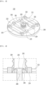
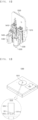
- FIG. 3 is a perspective view of the molding plate having the support fixing device 210
- FIG. 4 is a sectional view of the support fixing device 210.
- the support fixing device 210 includes: a support plate 200, an internal fixing part 201 formed at the center of the support plate 200; and an external fixing part 202 formed on the upper surface of the support plate.
- the support plate 200 is to support the support 220, and may be a disk shape as shown in FIG. 3 , but is not limited to the above, and may be formed into one of various flat plates to support the support 220.
- the support 220 is a hollow cylindrical support, and preferably, a hollow cylindrical support with a porous structure.
- a support 220 may be manufactured in a 3D printing manner in advance using polymer, but may be formed in advance using a 3D printer having the support fixing device.
- the polymer material may be selected from groups including thermoplastic polymer capable of performing FDM printing, such as lactide, caprolactone, glycolide, dioxanone, propylene, ethylene, vinylchloride, butadiene, methyl methacrylate, acrylic acid, 2-hydroxyethylmethacrylate, carbonate, and polyethylene terephalate, acrylonitrile butadiene styrene (ABS), polycaprolactone (PCL), acrylonitrile-styrene-acrylate (ASA), stryrene-acrylonitrile copolymer (SAN), polystyrene (PS), polyphenylsulfone (PPSF/PPSU), polyetherimide, polylactic acid (PLA), poly-d-lysine (PDL), and others.
- thermoplastic polymer capable of performing FDM printing such as lactide, caprolactone, glycolide, dioxanone, propylene, ethylene, vinylchloride, butadiene,
- the internal fixing part 201 comes into contact with the inner circumferential surface of the support 220 to fix the support 220.
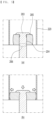
- the internal fixing part 201 includes: a tap hole 206 disposed in the middle of the support plate 200; a bolt 203 coupled with the tap hole 206; and an elastic tube 205 disposed on the outer circumferential surface of a screw part 204 of the bolt 203 (See FIG. 4 ).
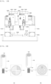
- the elastic tube 205 gets in contact with the outer circumferential surface of the screw part 204 of the bolt 203 ( FIG. 5(a) ), and the bolt 203 pressurizes the elastic tube 205 from the top when being coupled with the tap hole 206 disposed in the middle of the support plate 200, so that the elastic tube 205 expands in a radial direction (See FIG. 5(b) ).
- the elastic tube 205 expanding in the radial direction comes into contact with the inner circumferential surface of the support 220 so as to stably fix the support 220 in a vertical direction.
- the support 220 is located vertically so that the bolt 203 and the elastic tube 205 are included in an inner space thereof.
- the elastic tube 205 is pressurized downwards to expand in the radial direction and to come into contact with the inner circumferential surface of the support 220, so that the support 220 can be fixed onto the support plate 200 vertically.
- a diameter of the bolt 203 is smaller than the inner diameter of the support 220, and the outer diameter of the elastic tube 205 expanded in the radial direction is equal to or similar to the inner diameter of the support 220.
- a material of the elastic tube 205 is not limited specially, but preferably, is made of a material with elasticity so as to be changed in shape when being pressurized by the bolt 203.
- the elastic tube 205 may be made of at least one selected from groups containing silicone rubber, ethylene propylene rubber (EPM), ethylene propylene diene rubber (EPDM), chloroprene rubber (CR), thermoplastic elastomer (TPE), and thermoplastic olefin (TPO) .
- a strain rate of the elastic material is within 25% to 35% in contrast to the initial diameter.
- the support 220 is vertically fixed on the support plate 200 and it is prevented that the shape of the support 220 is damaged by pressure.
- the external fixing part 202 gets in contact with the outer circumferential surface of the support 220 to fix the support 220.
- the external fixing part 202 includes: a first fixing plate 221 formed at one end of the upper surface of the support plate 200; a second fixing plate 222 formed at the other end of the upper surface of the support plate 200; a guide 223 connecting the first fixing plate 221 and the second fixing plate 222 with each other; and a contact part 224 formed to be movable along the guide 223.
- the contact part 224 can move along the guide 223, after the support 220 is located vertically ( FIG. 6(a) ) so that the bolt 203 and the elastic tube 205 are included in the inner space of the support 220, when the contact part 224 is moved to get in contact with the outer circumferential surface of the support 220, the support 220 can be fixed more firmly in the vertical direction.
- the contact part 224 getting in contact with the outer circumferential surface of the support 220 is fixed by fixing means, such as a screw, a rubber ring, or adhesive resin so as to fix the support 220 more firmly.
- the contact part 224 includes a contact groove 225 formed in the surface getting in contact with the outer circumferential surface of the support 220.
- the contact groove 225 is to fix the support 220 more firmly by widening a contact area between the contact part 224 and the support 220, and has the shape corresponding to the shape of the outer circumferential surface of the support 220.
- the contact groove 225 may be formed in a curved shape having the radius of curvature which is the same as the support.
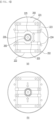
- FIGS. 7 and 8 show various modifications of the external fixing part 202.
- FIG. 7 illustrates the contact part 224 of a damper shape which gets in contact with the outer circumferential surface of the support 220 to fix the support 220
- FIG. 8 illustrates the contact part 224 of a plate spring shape. It is preferable that the contact part 224 of the damper shape or the plate spring shape gets in contact with the outer circumferential surface of the support 220 to have three or more contact points formed on the outer circumferential surface of the support to support at least three areas of the support 220.
- a lower end of the support 220 getting in contact with the contact part 224 may be formed into a sacrificial layer.
- the lower end of the support 220 fixed vertically is damaged by pressure applied due to contact of the contact part 224 or is damaged since load of the support 220 is inclined toward the lower end. So, the lower end of the support 220 is formed into the sacrificial layer, and then, the sacrificial layer is removed after completion of 3D printing so as to form a 3D structure without any damage.
- the height of the sacrificial layer is within 10% relative to the entire height of the support 220, and more preferably, is less than 10mm.
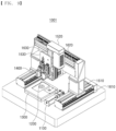
- FIG. 9 is a perspective view showing a 3D printing system for manufacturing an artificial blood vessel according to the present invention.
- the 3D printing system 1001 for manufacturing an artificial blood vessel according to the present invention includes: a support manufacturing unit 1100 which is rotatable and forms a hollow cylindrical support 1010 of a 3D porous structure when polymer is discharged to the outer circumferential surface through a first head 1200; the first head 1200 forming the hollow cylindrical support 1010 of the 3D porous structure when polymer is discharged to the support manufacturing unit 110; a holder 1300 for vertically holding the cylindrical support 1010 manufactured through the first head 1200; a second head 1400 for discharging hydrogel, which is divided into at least two sections, into the cylindrical support 1010 vertically held and fixed on the holder 1300; head moving units 1510, 1520 and 1530 for moving the first head 1200 and the second head 1400 at the same time or individually in horizontal and vertical directions; and a X-axis stage 1610, a Y-
- the support manufacturing unit 110 is rotatable, and is rotated when polymer is discharged to the outer circumferential surface through the first head 1200, so that the support 1010 is formed in a hollow cylindrical shape of a 3D porous structure.
- the diameter of the outer circumferential surface is equal to or similar to the diameter of a human blood vessel.
- the first head 1200 is moved along the Y-axis stage 1620 by the head moving unit 1520 and is located above the support manufacturing unit 1100. After that, the first head discharges polymer to the outer circumferential surface of the support manufacturing unit 1100 while moving along the X-axis stage 1610.
- the support manufacturing unit 110 is rotated at the same time. That is, because the polymer is discharged and the support manufacturing unit 1100 is rotated at the same time, the support 1010 can be formed in the hollow cylindrical shape of the 3D porous structure.
- the first head 1200 can discharge the polymer by pneumatic pressure, and pneumatic pressure is controlled properly according to concentration of the polymer or the size of a nozzle of the first head 1200 so as to control a discharge rate or discharge speed of the discharged polymer.
- the polymer is thermoplastic polymer, and is biodegradable polymer which is harmless inside or outside a living body and easily adjusts to intravital environment without any adverse reaction.
- thermoplastic polymer is not specially limited, but may contain at least one selected from groups including lactide, caprolactone, glycolide, dioxanone, propylene, ethylene, vinylchloride, butadiene, methyl methacrylate, acrylic acid, 2-hydroxyethylmethacrylate, carbonate, and polyethylene terephalate.
- the support 1010 including thermoplastic polymer can constantly maintain the structure and the form even after printing, has elasticity of a predetermined level, and is not easily damaged. Furthermore, the support 1010 can be fixed to biological tissues with a thread by the porous structure even in the case of clinical surgery (Refer to FIG. 25 ).
- the holder 1300 vertically fixes the support formed in the support manufacturing unit 1100 by the first head 1200, so that the second head 1400 can discharge hydrogel divided into at least two sections into the support 1010.
- the polymer gel may be at least one selected from groups including fucoidan, collagen, alginate, chitosan, hyaluronic acid, polycarprolactone, polyetherimide, nylon, polyaramid, polyvinyl alcohol, polyvinylpyrrolidone, poly-benzyl-glutamate, polyphenyleneterephthalamide, polyaniline, polyacrylonitrile, polyethylene oxide, polystyrene, cellulose, polyacrylate, polymethylmethacrylate, polylactic acid (PLA), polyglycolic acid (PGA), polylactide-polyglycolic acid copolymer (PLGA), poly(ethylene oxide terephthalate)-co-butylene terephthalate (PEOT/PBT), polyphosphoester (PPE), polyphosphagen (PPA), polyanhydride (PA), poly(orthoester (POE), poly (propylene fumarate)-diacrylate (PPF-DA), and poly (ethylene glycol) diacrylate
- the polymer gels may use chemically modified natural polymers, for instance, GelMA that gelatin and methacrylate are coupled chemically and photoinitiator is coupled, alginate/gelatin, and alginate in which pentapeptide sequencing Tyr-Ile-Gly-Ser-Arg (YIGSR) and EDC/NHS are combined to add binding site of alginate may be used.
- GelMA that gelatin and methacrylate are coupled chemically and photoinitiator is coupled
- alginate/gelatin alginate/gelatin
- alginate in which pentapeptide sequencing Tyr-Ile-Gly-Ser-Arg (YIGSR) and EDC/NHS are combined to add binding site of alginate may be used.
- the hydrogel such as polyethylene glycol, alginate, collagen and gelatin
- the hydrogel has been widely used in manufacturing a carrier in which cells are contained since being high in water content, is excellent at bio compatibility, being capable of controlling mechanical features, and is excellent at biodegradability. Therefore, the hydrogel is very suitable for manufacturing a cellmounted structure, and can be directly printed to obtain a tissue recovery frames of various types.
- the gelatin is especially suitable as a cell delivery material since being temperature-sensitive. That is, gelatin is liquefied at 37°C and is solidified at temperature less than normal temperature.
- the polymer gel may form a cross-link bond using physical treatment or chemical treatment, and can use a bridge solution for the chemical treatment and selectively use the bridge solution according to selected polymer gel.
- the bridge solution may be plaster; or a mixture solution of at least one kind selected from hydroxyapatite (HA), carbonate apatite, fluorapatite, chloroapatite, ⁇ -TCP, ⁇ -TCP, calcium metaphosphate, calcium-4-phosphate, calcium hydrogen phosphate, calcium hydrogen-2-phosphate, calcium pyrophosphate, calcium carbonate, calcium sulfate, and 1-ethyl-3(3-3-dimethylaminopropyl) carbodiimide hydrochloride (EDC), or may be a solution of mixture of at least one selected from salts thereof.
- HA hydroxyapatite
- fluorapatite fluorapatite
- chloroapatite ⁇ -TCP
- ⁇ -TCP calcium metaphosphate
- calcium-4-phosphate calcium hydrogen phosphate
- calcium hydrogen-2-phosphate calcium hydrogen-2-phosphate
- calcium pyrophosphate calcium carbonate
- calcium sulfate calcium sulf
- the ink containing the polymer gel solution is formed such that a collagen concentration ratio in a liquid-state collagen solution is within a range of 0.1 to 30% by weight.
- a method for manufacturing hydrogel may be performed applying the manufacturing method used when ink is manufactured by general 3D printing, but is not limited specially.
- the hydrogel divided into at least two sections may promote cross link of the hydrogel divided into at least two sections.
- Such cross link helps the hydrogel divided into at least two sections to be completed as a harder structure, and a photoinitiator may be used in order to promote the cross link.
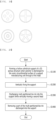
- the present invention relates to a method for manufacturing an artificial blood vessel (See FIG. 20 ).
- the method for manufacturing an artificial blood vessel includes: a step (S1100) of discharging polymer to the outer circumferential surface of the support manufacturing unit through the first head and forming a hollow cylindrical support of a 3D porous structure; a step (S1200) of vertically fixing the support; a step (S1300) of discharging the hydrogel divided into at least two sections into the support while vertically moving the second head; and a step (S1400) of removing a part of the hydrogel divided into at least two sections discharged into the support.
- An artificial blood vessel having a hollow multilayered structure can be manufactured through the method for manufacturing an artificial blood vessel according to the present invention.
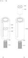
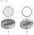
- step (S1100) of forming a hollow cylindrical support of a 3D porous structure polymer is discharged to the outer circumferential surface of the support manufacturing unit 1100 through the first head 1200 (See FIG. 21(a) ). Therefore, the hollow cylindrical support 1010 of the 3D porous structure (See FIG. 21(b) ) is formed.
- the step (S1100) includes a step of moving the first head above the support manufacturing unit. In this instance, the first head 1200 is moved along the Y-axis stage 1620 to be located above the support manufacturing unit 1100.
- the step (S1100) includes a step of rotating the support manufacturing unit.
- the step (S1100) further includes a step of discharging the polymer to the outer circumferential surface of the support manufacturing unit while moving the first head in a longitudinal direction of the support manufacturing unit.
- the rotating step and the discharging step are preferably carried out simultaneously or in consecutive order.
- the support manufacturing unit 1100 rotates when the first head 1200 discharges polymer to the outer circumferential surface of the support manufacturing unit 1100 while moving along the X-axis stage 1610, so that a hollow cylindrical support of the 3D porous structure can be formed.
- a step (S1200) of vertically fixing the support formed through the above steps is carried out, and preferably, the support 1010 can be vertically fixed on the holder 1300.
- a step (S1300) of discharging the hydrogel divided into at least two sections into the support while moving the second head vertically is carried out.
- the step (S1300) is carried out after moving the second head 1400 above the support 1010. That is, the second head 1400 moves along the Y-axis stage 1620 (See FIG. 21 ) by the head moving unit 1520 and is located above the support 1010. After that, the second head 1400 discharges the hydrogel divided into at least two sections into the support 1010 while ascending vertically. Therefore, the cross section of the hydrogel divided into at least two sections and discharged into the support 1010 and the cross section of the hydrogel divided into at least two sections and charged in the second head 1400 have the same pattern.
- a step (S1400) of removing a part of the hydrogel divided into at least two sections discharged into the support is carried out.
- the hydrogel divided into at least two sections discharged into the support 1010 includes a material of one or more kinds and has a multilayer structure, it is preferable to remove a part of the hydrogel corresponding to a middle part by changing gelation conditions of materials forming each layer.
- sodium alginate of 3 w/v% is formed outside, an artificial blood vessel formed with gelatin of 3%, which is hydrogel temperature-sensitive, is cross-linked to calcium chloride of 200 M inside.
- the artificial blood vessel 1020 manufactured according to the present invention is manufactured in the form of a hollow multilayered shape, and can uniformly maintain the structure and the form of the artificial blood vessel 1020 even after printing. Additionally, since the artificial blood vessel includes the hollow support of the 3D porous structure including thermoplastic polymer, it has excellent elasticity, is not easily damaged, and can be fixed to biological tissues with a thread by the porous structure of the support even in the case of clinical surgery.
- a partitioning member was manufactured using polyactic acid (PLA) through 3D printing.
- PLA polyactic acid
- a 3D printer using the second head was used, sizes of the nozzle were 1.2 mm (18 gauges), 0.9 mm (20 gauges), 0.7 mm (22 gauges), 0.5 mm (25 gauges), 0.42 (27 gauges), and a printed state of RGB hydrogel was check by a confocal microscope. It was confirmed that the 3D printer could be miniaturized in the same shape as the cross section of the second head.
- the ratio showed that the printed matter could be miniaturized from a specific shape (example: the entire diameter (15 mm) of Lobule) up to 98.7% (200 ⁇ m), the result was adjusted in Table 1, and the reduction ratio was calculated as in the Equation 1.
- Reduction ratio 100-(second head diameter/printed diameter) ⁇ 100(%) [Table 1] Div. Second head Nozzle Inner diameter 15mm 0.83mm 0.62mm 0.41mm 0.25mm 0.2mm Printing diameter 15mm 1mm 0.725mm 0.55mm 0.375mm 0.2mm Reduction(%) - 93.4 95.2 96.4 97.5 98.7 Reduction ratio - 100:15 100:11 100:3.7 100:2.5 100:1.3
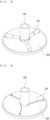
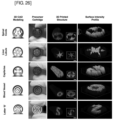
- FIG. 26 shows the result that the printed state of RGB hydrogel using the second head having the partitioning member of various shapes was observed by a confocal microscope.
- First hydrogel for filling made of 3 w/v% of sodium alginate was injected into the second head of the 3D printer.
- Sodium alginate of 3 w/v% containing green fluorescent particles was injected into the second head, in which the first hydrogel was injected, as second hydrogel by 3D printing using the 3D printer having a long nozzle.
- the first hydrogel for filling and the second hydrogel 3D-printed were printed by the 3D printing method using the output obtained through the second discharge unit by applying pressure. They were printed in three lines using the nozzle size (nozzle I.D) of 1.0 mm. In case that the nozzle having the nozzle size (nozzle I.D) of 1.0 mm was used, the cross section printed was 30 ⁇ m in length. In case that the nozzle having the nozzle size (nozzle I.D) of 2 mm was used, the cross section printed was 70 ⁇ m in length.
- the 3D printer using the second head like the third embodiment was used, sizes of the nozzle were 1.2 mm (18 gauges), 0.9 mm (20 gauges), 0.7 mm (22 gauges), 0.5 mm (25 gauges), 0.42 (27 gauges), and a printed state of hydrogel was check by a confocal microscope.
- the inner diameter of each nozzle of 1.2 mm (18 gauges), 0.9 mm (20 gauges), 0.7 mm (22 gauges), 0.5 mm (25 gauges), 0.42 (27 gauges) was 0.82 mm, 0.63 mm, 0.41 mm, 0.28 mm and 0.1 mm.
- the ratio showed that the printed matter could be miniaturized from a specific shape (example: the entire diameter (15 mm) of Lobule) up to 98.7% (200 ⁇ m), the result was adjusted in Table 2, and the reduction ratio was calculated as in the Equation 2.
- Reduction ratio of ink printed matter A ⁇ B / A ⁇ 100 % (in Equation 2, A is a cross section diameter of the first ink printed matter provided to the second head by 3D printing, B is a cross section diameter of the second ink printed matter, and A and B have the same length unit.) [Table 2] Cross section diameter (mm) of second head 9.
- 3 w/v% of sodium alginate was injected into the second head like the third embodiment, 3% gelatin which is temperature-sensitive hydrogel was injected into previously injected alginate by the printing method using the long nozzle.
- prepared complex hydrogel was printed to calcium chloride of 200 Mn, it was induced that only alginate became gel but gelatin did not become gel.
- the printed structure was put in liquid of 37°C, the alginate gel maintained the shape as it was, but gelatin was melted down to form the lumen structure.
- 3 w/v% of sodium alginate was injected into the second head like the seventh embodiment, 3% alginate in which smooth muscle cells were contained at concentration of more than 1 ⁇ 10 7 Cells/mL was injected into the 3% alginate using the 3D printer having the long nozzle, 3% gelatin in which vascular endothelial cells were contained at concentration of more than 1 ⁇ 10 7 Cells/mL was injected into alginate in which smooth muscle cells were contained.
- a blood vessel structure was copied.
- aorta or vena cava of the blood vessel are laid one upon another in a quadruple cylindrical structure.
- a blood vessel of the quadruple structure can be printed easily, and the size can be adjusted (See the copy result of the quadruple cylindrical structure using A, B, C and D of FIG. 27 ), and a double structure of venula or a single structure of a micro-vessel can be copied in the same way.
- the present invention relates to a three-dimensional (3D) printing system for manufacturing an artificial blood vessel and a method for manufacturing an artificial blood vessel using the same, wherein a cylindrical support having a hollow 3D porous structure including a thermoplastic polymer is manufactured and vertically fixed, and hydrogel divided into at least two sections is discharged into the support, thereby maintaining the structure and shape constantly even after printing and manufacturing an artificial blood vessel having a multilayered hollow structure.
- the present invention can manufacture an artificial blood vessel of a hollow form with a multilayer structure, and evenly maintain the structure and form of the artificial blood vessel even after printing. Therefore, the present invention has industrial applicability.
Landscapes
- Engineering & Computer Science (AREA)
- Chemical & Material Sciences (AREA)
- Materials Engineering (AREA)
- Manufacturing & Machinery (AREA)
- Mechanical Engineering (AREA)
- Physics & Mathematics (AREA)
- Optics & Photonics (AREA)
- Health & Medical Sciences (AREA)
- Cardiology (AREA)
- Vascular Medicine (AREA)
- Gastroenterology & Hepatology (AREA)
- Oral & Maxillofacial Surgery (AREA)
- Transplantation (AREA)
- Biomedical Technology (AREA)
- Heart & Thoracic Surgery (AREA)
- Pulmonology (AREA)
- Life Sciences & Earth Sciences (AREA)
- Animal Behavior & Ethology (AREA)
- General Health & Medical Sciences (AREA)
- Public Health (AREA)
- Veterinary Medicine (AREA)
- Prostheses (AREA)
Claims (8)
- Système d'impression 3D (1001, 1002, 1003) pour la fabrication d'un vaisseau sanguin artificiel, comprenant :une unité de fabrication de support (1100) qui est rotative et configurée pour former un support cylindrique creux (1010) d'une structure poreuse 3D lorsqu'un polymère est évacué vers la surface circonférentielle externe par l'intermédiaire d'une première tête (1200) ;dans lequel ladite première tête (1200) est configurée pour former le support cylindrique creux (1010) de la structure poreuse 3D par évacuation d'un polymère vers ladite unité de fabrication de support (1100) ;un dispositif de maintien (1300) configuré pour maintenir verticalement le support cylindrique creux (1010) fabriqué par l'intermédiaire de la première tête (1200) ; etune seconde tête (1400) configurée pour évacuer un hydrogel, qui est divisé en au moins deux sections, dans le support cylindrique creux (1010) maintenu verticalement et fixé sur le dispositif de maintien (1300).
- Système d'impression 3D (1001, 1002, 1003) selon la revendication 1, caractérisé en ce que la première tête (1200) comprend :un premier vérin pneumatique (1210) configuré pour s'élever et descendre afin d'évacuer le polymère ;une première unité d'évacuation (1220) configurée pour évacuer le polymère par abaissement du premier vérin pneumatique (1210) ; etune unité de contrôle de température (1220) configurée pour contrôler la température du polymère évacué.
- Système d'impression 3D (1001, 1002, 1003) selon la revendication 1, caractérisé en ce que la seconde tête (1400) comprend :un second vérin pneumatique (1410) configuré pour s'élever et descendre afin d'évacuer l'hydrogel ;une seconde unité d'évacuation (1420) configurée pour évacuer l'hydrogel divisé en au moins deux sections par abaissement du second vérin pneumatique (1410) ; etune unité de contrôle de température (1430) configurée pour contrôler la température de l'hydrogel évacué divisé en au moins deux sections.
- Système d'impression 3D (1001, 1002, 1003) selon la revendication 1, caractérisé en ce que l'unité de fabrication de support (1100) comprend :un arbre tournant (1110) qui est rotatif lorsque le polymère est évacué ;un moteur (1120) relié audit un côté de l'arbre tournant (1110) pour mettre en rotation l'arbre tournant (1110) ; etun palier (1130) relié à l'autre côté de l'arbre tournant (1110) pour supporter l'arbre tournant (1110).
- Système d'impression 3D (1001, 1002, 1003) selon la revendication 1, caractérisé en ce que la seconde tête (1400) est configurée pour évacuer l'hydrogel divisé en au moins deux sections dans le support cylindrique creux (1010) fixé verticalement sur le dispositif de maintien (1300).
- Système d'impression 3D (1001, 1002, 1003) selon la revendication 1, caractérisé en ce que le dispositif de maintien (1300) est mobile dans une direction verticale lorsque la seconde tête (1400) fixe évacue l'hydrogel divisé en au moins deux sections.
- Système d'impression 3D (1001, 1002, 1003) selon la revendication 1, caractérisé en ce que l'hydrogel divisé en au moins deux sections contient au moins un élément choisi parmi des groupes incluant des gels de polymère, des cellules, des facteurs de croissance, et une matrice extracellulaire, et
caractérisé en ce qu'une coupe de l'hydrogel divisé en l'au moins deux sections évacué dans le support cylindrique creux (1010) et une coupe de l'hydrogel divisé en l'au moins deux sections chargé dans le second vérin pneumatique (1410) présentent le même motif. - Procédé de fabrication d'un vaisseau sanguin artificiel comprenant les étapes de :formation d' un support cylindrique creux (1010) d'une structure poreuse 3D (S1100) par évacuation d'un polymère vers la surface circonférentielle externe d'une unité de fabrication de support (1100) par l'intermédiaire d'une première tête (1200) ;fixation verticale du support cylindrique (S1200) ; etévacuation d'un hydrogel (S1300), qui est divisé en au moins deux sections, dans le support tout en mettant en mouvement verticalement une seconde tête (1400), après avoir mis en mouvement la seconde tête (1400) au-dessus du support (1010), de sorte que la seconde tête (1400) se met en mouvement le long d'une platine d'axe Y (1620) par une unité de mise en mouvement de tête (1520) et est placée au-dessus du support (1010), par la suite, la seconde tête (1400) évacue l'hydrogel divisé en au moins deux sections dans le support (1010) tout en s'élevant verticalement ;dans lequel une coupe de l'hydrogel divisé en l'au moins deux sections évacué dans le support (1010) et une coupe de l'hydrogel divisé en l'au moins deux sections chargé dans la seconde tête (1400) présentent le même motif, dans lequel l'étape (S1100) de formation du support comprend les étapes de :mise en mouvement de la première tête (1200) au-dessus de l'unité de fabrication du support (1100), dans lequel la première tête (1200) est mise en mouvement le long de la platine d'axe Y (1620) pour être placée au-dessus de l'unité de fabrication de support (1100) ;rotation de l'unité de fabrication de support (1100) après avoir placé la première tête (1200) au-dessus de l'unité de fabrication de support (1100) ; etévacuation du polymère vers la surface circonférentielle externe de l'unité de fabrication de support (1100) tout en mettant en mouvement la première tête (1200) dans une direction longitudinale de l'unité de fabrication de support (1100),dans lequel l'étape de rotation et l'étape d'évacuation sont effectuées en même temps ou sont effectuées dans un ordre consécutif, etdans lequel le procédé comprend en outre l'étape de retrait d'une partie de l'hydrogel divisé en au moins deux sections évacué dans le support (1100) (S1400) après l'étape d'évacuation (S1300).
Applications Claiming Priority (2)
| Application Number | Priority Date | Filing Date | Title |
|---|---|---|---|
| KR1020190153497A KR102253724B1 (ko) | 2019-11-26 | 2019-11-26 | 회전형 3d 프린팅 조형판 및 이를 포함하는 3d 프린터 |
| PCT/KR2019/017877 WO2021107252A1 (fr) | 2019-11-26 | 2019-12-17 | Système d'impression 3d pour fabriquer des vaisseaux sanguins artificiels, et procédé de fabrication de vaisseaux sanguins artificiels au moyen de celui-ci |
Publications (5)
| Publication Number | Publication Date |
|---|---|
| EP3848183A1 EP3848183A1 (fr) | 2021-07-14 |
| EP3848183A8 EP3848183A8 (fr) | 2021-09-15 |
| EP3848183A4 EP3848183A4 (fr) | 2022-05-04 |
| EP3848183C0 EP3848183C0 (fr) | 2024-11-20 |
| EP3848183B1 true EP3848183B1 (fr) | 2024-11-20 |
Family
ID=76130302
Family Applications (1)
| Application Number | Title | Priority Date | Filing Date |
|---|---|---|---|
| EP19929182.4A Active EP3848183B1 (fr) | 2019-11-26 | 2019-12-17 | Système d'impression 3d pour fabriquer des vaisseaux sanguins artificiels, et procédé de fabrication de vaisseaux sanguins artificiels au moyen de celui-ci |
Country Status (6)
| Country | Link |
|---|---|
| US (1) | US12030255B2 (fr) |
| EP (1) | EP3848183B1 (fr) |
| JP (1) | JP7303594B2 (fr) |
| KR (1) | KR102253724B1 (fr) |
| CN (1) | CN114728470B (fr) |
| WO (1) | WO2021107252A1 (fr) |
Families Citing this family (2)
| Publication number | Priority date | Publication date | Assignee | Title |
|---|---|---|---|---|
| TR2021020673A2 (tr) * | 2021-12-22 | 2022-01-21 | T C Ankara Ueniversitesi Rektoerluegue | Doğal, elasti̇k, bi̇yoakti̇f özelli̇klerde bi̇r damar grefti̇ |
| KR102799299B1 (ko) * | 2022-02-22 | 2025-04-29 | 한국기계연구원 | 인공조직 제조장치 |
Family Cites Families (31)
| Publication number | Priority date | Publication date | Assignee | Title |
|---|---|---|---|---|
| JPS58157465A (ja) * | 1982-03-15 | 1983-09-19 | オンタリオ・リサ−チ・フアンデ−シヨン | 多孔性チユ−ブ製品の形成方法 |
| JPS58157465U (ja) | 1982-04-15 | 1983-10-20 | 山下 駿一郎 | 伸縮自在キルテイング |
| WO2010151767A1 (fr) * | 2009-06-25 | 2010-12-29 | 3D Biotek Llc | Procédés et appareil pour fabriquer des échafaudages tubulaires tridimensionnels poreux |
| KR101067827B1 (ko) | 2010-03-19 | 2011-09-27 | 포항공과대학교 산학협력단 | 3차원 인공 지지체 및 그 제조방법 |
| JP2014151524A (ja) * | 2013-02-07 | 2014-08-25 | Tokai Univ | 中空部を有する三次元構造体およびその製造方法 |
| US10150258B2 (en) | 2013-07-29 | 2018-12-11 | Carnegie Mellon University | Additive manufacturing of embedded materials |
| CN104607681A (zh) | 2013-11-03 | 2015-05-13 | 西安志越机电科技有限公司 | 薄壁圆管车削夹紧装置 |
| KR101519922B1 (ko) | 2014-07-21 | 2015-05-14 | 한국기계연구원 | 약물방출 스텐트 및 그 제조 방법 |
| DE202014103517U1 (de) * | 2014-07-29 | 2015-01-09 | Andreas Weidner | Haltevorrichtung |
| GB201501089D0 (en) | 2015-01-22 | 2015-03-11 | Univ Greenwich | Stent |
| KR20160096829A (ko) | 2015-02-06 | 2016-08-17 | 한국기계연구원 | 바이오 프린팅 기술을 이용한 3차원 하이드로겔 스캐폴드 제조 방법 |
| EP3278765B1 (fr) | 2015-03-31 | 2020-06-17 | Revotek Co., Ltd | Plateforme 3d bio-impression comprenant un dispositif rotatif, et procédé d'utilisation associé |
| WO2016201577A1 (fr) | 2015-06-16 | 2016-12-22 | Aspect Biosystems Ltd. | Structure tissulaire multicouche bio-imprimée en continu |
| KR101791892B1 (ko) | 2015-07-14 | 2017-11-01 | 한국기계연구원 | 약물코팅 스텐트 제조장치 및 이를 이용한 약물코팅 스텐트 제조방법 |
| ITUB20153684A1 (it) | 2015-07-24 | 2017-01-24 | Univ Degli Studi Di Trieste | Dispositivo di fabbricazione additiva per realizzare un oggetto tridimensionale. |
| WO2017087904A1 (fr) | 2015-11-20 | 2017-05-26 | Organovo, Inc. | Dispositif rotatif et procédé de fabrication en continu de longs tubes biologique |
| KR101795559B1 (ko) | 2016-01-07 | 2017-11-08 | 주식회사 티앤알바이오팹 | 열민감성 세포프린팅 조성물의 세포 프린팅 장치 |
| CN205519737U (zh) | 2016-01-20 | 2016-08-31 | 昆明理工大学 | 橡胶外胀式定心夹具 |
| US10953594B2 (en) | 2016-04-01 | 2021-03-23 | T & R Biofab Co., Ltd. | Method for manufacturing printout having cross-sectional pattern |
| KR101975200B1 (ko) | 2016-06-02 | 2019-05-07 | 주식회사 티앤알바이오팹 | 바이오 잉크 3차원 프린팅 장치 |
| CN107411844B (zh) | 2016-09-14 | 2020-06-30 | 四川蓝光英诺生物科技股份有限公司 | 管腔组织构建体及其制备方法、制备装置 |
| KR101863192B1 (ko) | 2016-12-05 | 2018-06-29 | 주식회사 티앤알바이오팹 | 3d프린팅 스텐트 시술용 카테터, 시술용 카테터를 고정하기 위한 지그 및 이를 이용한 3d프린팅 스텐트 제조방법 |
| CN106806945A (zh) | 2016-12-21 | 2017-06-09 | 青岛三帝生物科技有限公司 | 小口径生物人工血管的3d打印制备方法和人工血管 |
| JP6915328B2 (ja) | 2017-03-17 | 2021-08-04 | 株式会社リコー | 立体構造物の製造方法 |
| CN107296983B (zh) | 2017-05-22 | 2020-10-30 | 上海大学 | 一种骨组织三维微纳尺度预制血管网络的构建系统和方法 |
| KR101974999B1 (ko) | 2017-05-29 | 2019-08-26 | 포항공과대학교 산학협력단 | 호흡기관 대체 삼차원 지지체의 제조방법 |
| DE202018106923U1 (de) | 2017-12-12 | 2018-12-14 | Rocada, S. L. | Vorrichtung zum Befestigen von Schieferplatten auf einem Befestigungsbock und Schiefer, der diese Vorrichtung umfasst |
| KR102027780B1 (ko) * | 2018-06-19 | 2019-10-18 | 주식회사 쓰리딜라이트 | 가변적인 3d프린터의 배트 |
| KR102083788B1 (ko) | 2018-09-04 | 2020-03-03 | 주식회사 티앤알바이오팹 | 인공 혈관 제조용 3d 프린팅 시스템 및 이를 이용한 인공 혈관의 제조 방법 |
| CN110004058B (zh) | 2019-04-04 | 2020-07-10 | 西安交通大学 | 多尺度纤维增强的微流道活性管状组织3d打印装置及方法 |
| CN110480540B (zh) | 2019-08-21 | 2021-03-23 | 中原内配集团安徽有限责任公司 | 一种点阵式柔性缸套外圆夹具 |
-
2019
- 2019-11-26 KR KR1020190153497A patent/KR102253724B1/ko active Active
- 2019-12-17 WO PCT/KR2019/017877 patent/WO2021107252A1/fr not_active Ceased
- 2019-12-17 JP JP2022530868A patent/JP7303594B2/ja active Active
- 2019-12-17 US US17/059,401 patent/US12030255B2/en active Active
- 2019-12-17 CN CN201980102473.3A patent/CN114728470B/zh active Active
- 2019-12-17 EP EP19929182.4A patent/EP3848183B1/fr active Active
Also Published As
| Publication number | Publication date |
|---|---|
| CN114728470A (zh) | 2022-07-08 |
| JP2023504034A (ja) | 2023-02-01 |
| US12030255B2 (en) | 2024-07-09 |
| US20210379835A1 (en) | 2021-12-09 |
| EP3848183C0 (fr) | 2024-11-20 |
| CN114728470B (zh) | 2024-04-16 |
| EP3848183A1 (fr) | 2021-07-14 |
| JP7303594B2 (ja) | 2023-07-05 |
| EP3848183A4 (fr) | 2022-05-04 |
| KR102253724B1 (ko) | 2021-05-20 |
| EP3848183A8 (fr) | 2021-09-15 |
| WO2021107252A1 (fr) | 2021-06-03 |
Similar Documents
| Publication | Publication Date | Title |
|---|---|---|
| EP3453523B1 (fr) | Procédé d'alimentation en encre pour impression 3d et procédé d'impression 3d l'utilisant | |
| KR102083788B1 (ko) | 인공 혈관 제조용 3d 프린팅 시스템 및 이를 이용한 인공 혈관의 제조 방법 | |
| EP3438241B1 (fr) | Procédé et appareil de fabrication d'imprimé ayant un motif à section transversal | |
| JP7853348B2 (ja) | バイオ印刷された半月板移植片及びその使用方法 | |
| Wu et al. | Digital light processing‐based multi‐material bioprinting: Processes, applications, and perspectives | |
| EP2768425B1 (fr) | Procédés et dispositifs de liaison de nerfs | |
| US20060085063A1 (en) | Nano- and micro-scale engineering of polymeric scaffolds for vascular tissue engineering | |
| WO2010030964A2 (fr) | Hydrogels multicouches tridimensionnels et leurs procédés de préparation | |
| Wang et al. | A review on 3D printing processes in pharmaceutical engineering and tissue engineering: applications, trends and challenges | |
| WO2006096454A1 (fr) | Implant de nucleus pulposus pouvant se former in situ ayant une capacite d’absorption d’eau et de gonflement | |
| Burg et al. | Minimally invasive tissue engineering composites and cell printing | |
| CN105013011A (zh) | 一种组织工程半月板支架的3d生物打印制备方法 | |
| US12030255B2 (en) | 3D printing system for manufacturing artificial blood vessel and method for manufacturing artificial blood vessel using same | |
| Gillispie et al. | Three-dimensional tissue and organ printing in regenerative medicine | |
| KR102640278B1 (ko) | 바이오 잉크 조성물 및 이를 이용한 3차원 지방 및 피부 복합 조직 유사 구조체의 제조방법 | |
| Yadav et al. | Artificial tissues and organs: revolutionizing and pioneering the future of medicine and healthcare | |
| Biswas et al. | Introduction of 3D Printing and Different Bioprinting Methods | |
| WO2017171493A1 (fr) | Procédé et appareil de fabrication d'imprimé ayant un motif à section transversal | |
| WO2017192004A1 (fr) | Procédé d'alimentation en encre pour impression 3d et procédé d'impression 3d l'utilisant | |
| Sami et al. | Pneumatic Extrusion of Biomaterials | |
| Aghajanzadeh et al. | 3D Printing Artificial Structures for Musculoskeletal Tissue Repair | |
| Şentürk | 3D bioprinting of osteochondrial interface tissue |
Legal Events
| Date | Code | Title | Description |
|---|---|---|---|
| STAA | Information on the status of an ep patent application or granted ep patent |
Free format text: STATUS: UNKNOWN |
|
| STAA | Information on the status of an ep patent application or granted ep patent |
Free format text: STATUS: THE INTERNATIONAL PUBLICATION HAS BEEN MADE |
|
| PUAI | Public reference made under article 153(3) epc to a published international application that has entered the european phase |
Free format text: ORIGINAL CODE: 0009012 |
|
| STAA | Information on the status of an ep patent application or granted ep patent |
Free format text: STATUS: REQUEST FOR EXAMINATION WAS MADE |
|
| 17P | Request for examination filed |
Effective date: 20201124 |
|
| AK | Designated contracting states |
Kind code of ref document: A1 Designated state(s): AL AT BE BG CH CY CZ DE DK EE ES FI FR GB GR HR HU IE IS IT LI LT LU LV MC MK MT NL NO PL PT RO RS SE SI SK SM TR |
|
| RIN1 | Information on inventor provided before grant (corrected) |
Inventor name: LEE, IN GYU Inventor name: MIN, KYUNG HYUN Inventor name: KIM, MIN KYUNG Inventor name: AHN, GEUN SEON |
|
| RIC1 | Information provided on ipc code assigned before grant |
Ipc: B33Y 80/00 20150101ALI20211110BHEP Ipc: B33Y 10/00 20150101ALI20211110BHEP Ipc: B29C 64/106 20170101ALI20211110BHEP Ipc: A61F 2/06 20130101ALI20211110BHEP Ipc: A61L 27/52 20060101ALI20211110BHEP Ipc: A61L 27/50 20060101ALI20211110BHEP Ipc: B33Y 70/00 20200101ALI20211110BHEP Ipc: B33Y 40/00 20200101ALI20211110BHEP Ipc: B33Y 30/00 20150101ALI20211110BHEP Ipc: B29C 64/30 20170101ALI20211110BHEP Ipc: B29C 64/227 20170101ALI20211110BHEP Ipc: B29C 64/209 20170101AFI20211110BHEP |
|
| A4 | Supplementary search report drawn up and despatched |
Effective date: 20220404 |
|
| RIC1 | Information provided on ipc code assigned before grant |
Ipc: B24B 41/06 20120101ALI20220329BHEP Ipc: B25B 5/14 20060101ALI20220329BHEP Ipc: B25B 5/10 20060101ALI20220329BHEP Ipc: B33Y 80/00 20150101ALI20220329BHEP Ipc: B33Y 10/00 20150101ALI20220329BHEP Ipc: B29C 64/106 20170101ALI20220329BHEP Ipc: A61F 2/06 20130101ALI20220329BHEP Ipc: A61L 27/52 20060101ALI20220329BHEP Ipc: A61L 27/50 20060101ALI20220329BHEP Ipc: B33Y 70/00 20200101ALI20220329BHEP Ipc: B33Y 40/00 20200101ALI20220329BHEP Ipc: B33Y 30/00 20150101ALI20220329BHEP Ipc: B29C 64/30 20170101ALI20220329BHEP Ipc: B29C 64/227 20170101ALI20220329BHEP Ipc: B29C 64/209 20170101AFI20220329BHEP |
|
| STAA | Information on the status of an ep patent application or granted ep patent |
Free format text: STATUS: EXAMINATION IS IN PROGRESS |
|
| 17Q | First examination report despatched |
Effective date: 20230112 |
|
| DAV | Request for validation of the european patent (deleted) | ||
| DAX | Request for extension of the european patent (deleted) | ||
| GRAP | Despatch of communication of intention to grant a patent |
Free format text: ORIGINAL CODE: EPIDOSNIGR1 |
|
| STAA | Information on the status of an ep patent application or granted ep patent |
Free format text: STATUS: GRANT OF PATENT IS INTENDED |
|
| INTG | Intention to grant announced |
Effective date: 20240617 |
|
| GRAS | Grant fee paid |
Free format text: ORIGINAL CODE: EPIDOSNIGR3 |
|
| GRAA | (expected) grant |
Free format text: ORIGINAL CODE: 0009210 |
|
| STAA | Information on the status of an ep patent application or granted ep patent |
Free format text: STATUS: THE PATENT HAS BEEN GRANTED |
|
| AK | Designated contracting states |
Kind code of ref document: B1 Designated state(s): AL AT BE BG CH CY CZ DE DK EE ES FI FR GB GR HR HU IE IS IT LI LT LU LV MC MK MT NL NO PL PT RO RS SE SI SK SM TR |
|
| REG | Reference to a national code |
Ref country code: GB Ref legal event code: FG4D |
|
| REG | Reference to a national code |
Ref country code: CH Ref legal event code: EP |
|
| REG | Reference to a national code |
Ref country code: DE Ref legal event code: R096 Ref document number: 602019062432 Country of ref document: DE |
|
| REG | Reference to a national code |
Ref country code: IE Ref legal event code: FG4D |
|
| U01 | Request for unitary effect filed |
Effective date: 20241129 |
|
| U07 | Unitary effect registered |
Designated state(s): AT BE BG DE DK EE FI FR IT LT LU LV MT NL PT RO SE SI Effective date: 20241210 |
|
| U20 | Renewal fee for the european patent with unitary effect paid |
Year of fee payment: 6 Effective date: 20241227 |
|
| PG25 | Lapsed in a contracting state [announced via postgrant information from national office to epo] |
Ref country code: HR Free format text: LAPSE BECAUSE OF FAILURE TO SUBMIT A TRANSLATION OF THE DESCRIPTION OR TO PAY THE FEE WITHIN THE PRESCRIBED TIME-LIMIT Effective date: 20241120 Ref country code: IS Free format text: LAPSE BECAUSE OF FAILURE TO SUBMIT A TRANSLATION OF THE DESCRIPTION OR TO PAY THE FEE WITHIN THE PRESCRIBED TIME-LIMIT Effective date: 20250320 |
|
| PG25 | Lapsed in a contracting state [announced via postgrant information from national office to epo] |
Ref country code: ES Free format text: LAPSE BECAUSE OF FAILURE TO SUBMIT A TRANSLATION OF THE DESCRIPTION OR TO PAY THE FEE WITHIN THE PRESCRIBED TIME-LIMIT Effective date: 20241120 |
|
| PG25 | Lapsed in a contracting state [announced via postgrant information from national office to epo] |
Ref country code: NO Free format text: LAPSE BECAUSE OF FAILURE TO SUBMIT A TRANSLATION OF THE DESCRIPTION OR TO PAY THE FEE WITHIN THE PRESCRIBED TIME-LIMIT Effective date: 20250220 |
|
| PG25 | Lapsed in a contracting state [announced via postgrant information from national office to epo] |
Ref country code: GR Free format text: LAPSE BECAUSE OF FAILURE TO SUBMIT A TRANSLATION OF THE DESCRIPTION OR TO PAY THE FEE WITHIN THE PRESCRIBED TIME-LIMIT Effective date: 20250221 |
|
| PG25 | Lapsed in a contracting state [announced via postgrant information from national office to epo] |
Ref country code: PL Free format text: LAPSE BECAUSE OF FAILURE TO SUBMIT A TRANSLATION OF THE DESCRIPTION OR TO PAY THE FEE WITHIN THE PRESCRIBED TIME-LIMIT Effective date: 20241120 |
|
| PG25 | Lapsed in a contracting state [announced via postgrant information from national office to epo] |
Ref country code: RS Free format text: LAPSE BECAUSE OF FAILURE TO SUBMIT A TRANSLATION OF THE DESCRIPTION OR TO PAY THE FEE WITHIN THE PRESCRIBED TIME-LIMIT Effective date: 20250220 |
|
| PG25 | Lapsed in a contracting state [announced via postgrant information from national office to epo] |
Ref country code: SM Free format text: LAPSE BECAUSE OF FAILURE TO SUBMIT A TRANSLATION OF THE DESCRIPTION OR TO PAY THE FEE WITHIN THE PRESCRIBED TIME-LIMIT Effective date: 20241120 |
|
| PG25 | Lapsed in a contracting state [announced via postgrant information from national office to epo] |
Ref country code: SK Free format text: LAPSE BECAUSE OF FAILURE TO SUBMIT A TRANSLATION OF THE DESCRIPTION OR TO PAY THE FEE WITHIN THE PRESCRIBED TIME-LIMIT Effective date: 20241120 |
|
| PG25 | Lapsed in a contracting state [announced via postgrant information from national office to epo] |
Ref country code: CZ Free format text: LAPSE BECAUSE OF FAILURE TO SUBMIT A TRANSLATION OF THE DESCRIPTION OR TO PAY THE FEE WITHIN THE PRESCRIBED TIME-LIMIT Effective date: 20241120 |
|
| REG | Reference to a national code |
Ref country code: CH Ref legal event code: PL |
|
| PG25 | Lapsed in a contracting state [announced via postgrant information from national office to epo] |
Ref country code: MC Free format text: LAPSE BECAUSE OF FAILURE TO SUBMIT A TRANSLATION OF THE DESCRIPTION OR TO PAY THE FEE WITHIN THE PRESCRIBED TIME-LIMIT Effective date: 20241120 |
|
| PLBE | No opposition filed within time limit |
Free format text: ORIGINAL CODE: 0009261 |
|
| STAA | Information on the status of an ep patent application or granted ep patent |
Free format text: STATUS: NO OPPOSITION FILED WITHIN TIME LIMIT |
|
| PG25 | Lapsed in a contracting state [announced via postgrant information from national office to epo] |
Ref country code: CH Free format text: LAPSE BECAUSE OF NON-PAYMENT OF DUE FEES Effective date: 20241231 |
|
| 26N | No opposition filed |
Effective date: 20250821 |
|
| PG25 | Lapsed in a contracting state [announced via postgrant information from national office to epo] |
Ref country code: IE Free format text: LAPSE BECAUSE OF NON-PAYMENT OF DUE FEES Effective date: 20241217 |
|
| GBPC | Gb: european patent ceased through non-payment of renewal fee |
Effective date: 20250220 |
|
| PG25 | Lapsed in a contracting state [announced via postgrant information from national office to epo] |
Ref country code: GB Free format text: LAPSE BECAUSE OF NON-PAYMENT OF DUE FEES Effective date: 20250220 |
|
| U20 | Renewal fee for the european patent with unitary effect paid |
Year of fee payment: 7 Effective date: 20251229 |
|
| PG25 | Lapsed in a contracting state [announced via postgrant information from national office to epo] |
Ref country code: CY Free format text: LAPSE BECAUSE OF FAILURE TO SUBMIT A TRANSLATION OF THE DESCRIPTION OR TO PAY THE FEE WITHIN THE PRESCRIBED TIME-LIMIT Effective date: 20241120 |