EP3848559B1 - Moteur à turbine à gaz comportant un amortisseur à film comprimé avec réservoir - Google Patents
Moteur à turbine à gaz comportant un amortisseur à film comprimé avec réservoir Download PDFInfo
- Publication number
- EP3848559B1 EP3848559B1 EP21150215.8A EP21150215A EP3848559B1 EP 3848559 B1 EP3848559 B1 EP 3848559B1 EP 21150215 A EP21150215 A EP 21150215A EP 3848559 B1 EP3848559 B1 EP 3848559B1
- Authority
- EP
- European Patent Office
- Prior art keywords
- cavity
- reservoir
- gas turbine
- turbine engine
- recited
- Prior art date
- Legal status (The legal status is an assumption and is not a legal conclusion. Google has not performed a legal analysis and makes no representation as to the accuracy of the status listed.)
- Active
Links
Images




Classifications
-
- F—MECHANICAL ENGINEERING; LIGHTING; HEATING; WEAPONS; BLASTING
- F01—MACHINES OR ENGINES IN GENERAL; ENGINE PLANTS IN GENERAL; STEAM ENGINES
- F01D—NON-POSITIVE DISPLACEMENT MACHINES OR ENGINES, e.g. STEAM TURBINES
- F01D25/00—Component parts, details, or accessories, not provided for in, or of interest apart from, other groups
- F01D25/16—Arrangement of bearings; Supporting or mounting bearings in casings
- F01D25/162—Bearing supports
- F01D25/164—Flexible supports; Vibration damping means associated with the bearing
-
- F—MECHANICAL ENGINEERING; LIGHTING; HEATING; WEAPONS; BLASTING
- F02—COMBUSTION ENGINES; HOT-GAS OR COMBUSTION-PRODUCT ENGINE PLANTS
- F02C—GAS-TURBINE PLANTS; AIR INTAKES FOR JET-PROPULSION PLANTS; CONTROLLING FUEL SUPPLY IN AIR-BREATHING JET-PROPULSION PLANTS
- F02C7/00—Features, components parts, details or accessories, not provided for in, or of interest apart form groups F02C1/00 - F02C6/00; Air intakes for jet-propulsion plants
- F02C7/06—Arrangements of bearings; Lubricating
-
- F—MECHANICAL ENGINEERING; LIGHTING; HEATING; WEAPONS; BLASTING
- F01—MACHINES OR ENGINES IN GENERAL; ENGINE PLANTS IN GENERAL; STEAM ENGINES
- F01D—NON-POSITIVE DISPLACEMENT MACHINES OR ENGINES, e.g. STEAM TURBINES
- F01D25/00—Component parts, details, or accessories, not provided for in, or of interest apart from, other groups
- F01D25/18—Lubricating arrangements
-
- F—MECHANICAL ENGINEERING; LIGHTING; HEATING; WEAPONS; BLASTING
- F01—MACHINES OR ENGINES IN GENERAL; ENGINE PLANTS IN GENERAL; STEAM ENGINES
- F01D—NON-POSITIVE DISPLACEMENT MACHINES OR ENGINES, e.g. STEAM TURBINES
- F01D25/00—Component parts, details, or accessories, not provided for in, or of interest apart from, other groups
- F01D25/18—Lubricating arrangements
- F01D25/20—Lubricating arrangements using lubrication pumps
-
- F—MECHANICAL ENGINEERING; LIGHTING; HEATING; WEAPONS; BLASTING
- F01—MACHINES OR ENGINES IN GENERAL; ENGINE PLANTS IN GENERAL; STEAM ENGINES
- F01D—NON-POSITIVE DISPLACEMENT MACHINES OR ENGINES, e.g. STEAM TURBINES
- F01D25/00—Component parts, details, or accessories, not provided for in, or of interest apart from, other groups
- F01D25/18—Lubricating arrangements
- F01D25/22—Lubricating arrangements using working-fluid or other gaseous fluid as lubricant
-
- F—MECHANICAL ENGINEERING; LIGHTING; HEATING; WEAPONS; BLASTING
- F01—MACHINES OR ENGINES IN GENERAL; ENGINE PLANTS IN GENERAL; STEAM ENGINES
- F01D—NON-POSITIVE DISPLACEMENT MACHINES OR ENGINES, e.g. STEAM TURBINES
- F01D9/00—Stators
- F01D9/06—Fluid supply conduits to nozzles or the like
- F01D9/065—Fluid supply or removal conduits traversing the working fluid flow, e.g. for lubrication-, cooling-, or sealing fluids
-
- F—MECHANICAL ENGINEERING; LIGHTING; HEATING; WEAPONS; BLASTING
- F16—ENGINEERING ELEMENTS AND UNITS; GENERAL MEASURES FOR PRODUCING AND MAINTAINING EFFECTIVE FUNCTIONING OF MACHINES OR INSTALLATIONS; THERMAL INSULATION IN GENERAL
- F16C—SHAFTS; FLEXIBLE SHAFTS; ELEMENTS OR CRANKSHAFT MECHANISMS; ROTARY BODIES OTHER THAN GEARING ELEMENTS; BEARINGS
- F16C27/00—Elastic or yielding bearings or bearing supports, for exclusively rotary movement
- F16C27/04—Ball or roller bearings, e.g. with resilient rolling bodies
- F16C27/045—Ball or roller bearings, e.g. with resilient rolling bodies with a fluid film, e.g. squeeze film damping
-
- F—MECHANICAL ENGINEERING; LIGHTING; HEATING; WEAPONS; BLASTING
- F16—ENGINEERING ELEMENTS AND UNITS; GENERAL MEASURES FOR PRODUCING AND MAINTAINING EFFECTIVE FUNCTIONING OF MACHINES OR INSTALLATIONS; THERMAL INSULATION IN GENERAL
- F16C—SHAFTS; FLEXIBLE SHAFTS; ELEMENTS OR CRANKSHAFT MECHANISMS; ROTARY BODIES OTHER THAN GEARING ELEMENTS; BEARINGS
- F16C33/00—Parts of bearings; Special methods for making bearings or parts thereof
- F16C33/72—Sealings
- F16C33/74—Sealings of sliding-contact bearings
-
- F—MECHANICAL ENGINEERING; LIGHTING; HEATING; WEAPONS; BLASTING
- F16—ENGINEERING ELEMENTS AND UNITS; GENERAL MEASURES FOR PRODUCING AND MAINTAINING EFFECTIVE FUNCTIONING OF MACHINES OR INSTALLATIONS; THERMAL INSULATION IN GENERAL
- F16F—SPRINGS; SHOCK-ABSORBERS; MEANS FOR DAMPING VIBRATION
- F16F15/00—Suppression of vibrations in systems; Means or arrangements for avoiding or reducing out-of-balance forces, e.g. due to motion
- F16F15/02—Suppression of vibrations of non-rotating, e.g. reciprocating systems; Suppression of vibrations of rotating systems by use of members not moving with the rotating systems
- F16F15/023—Suppression of vibrations of non-rotating, e.g. reciprocating systems; Suppression of vibrations of rotating systems by use of members not moving with the rotating systems using fluid means
- F16F15/0237—Suppression of vibrations of non-rotating, e.g. reciprocating systems; Suppression of vibrations of rotating systems by use of members not moving with the rotating systems using fluid means involving squeeze-film damping
-
- F—MECHANICAL ENGINEERING; LIGHTING; HEATING; WEAPONS; BLASTING
- F05—INDEXING SCHEMES RELATING TO ENGINES OR PUMPS IN VARIOUS SUBCLASSES OF CLASSES F01-F04
- F05D—INDEXING SCHEME FOR ASPECTS RELATING TO NON-POSITIVE-DISPLACEMENT MACHINES OR ENGINES, GAS-TURBINES OR JET-PROPULSION PLANTS
- F05D2220/00—Application
- F05D2220/30—Application in turbines
- F05D2220/32—Application in turbines in gas turbines
- F05D2220/323—Application in turbines in gas turbines for aircraft propulsion, e.g. jet engines
-
- F—MECHANICAL ENGINEERING; LIGHTING; HEATING; WEAPONS; BLASTING
- F05—INDEXING SCHEMES RELATING TO ENGINES OR PUMPS IN VARIOUS SUBCLASSES OF CLASSES F01-F04
- F05D—INDEXING SCHEME FOR ASPECTS RELATING TO NON-POSITIVE-DISPLACEMENT MACHINES OR ENGINES, GAS-TURBINES OR JET-PROPULSION PLANTS
- F05D2220/00—Application
- F05D2220/40—Application in turbochargers
-
- F—MECHANICAL ENGINEERING; LIGHTING; HEATING; WEAPONS; BLASTING
- F05—INDEXING SCHEMES RELATING TO ENGINES OR PUMPS IN VARIOUS SUBCLASSES OF CLASSES F01-F04
- F05D—INDEXING SCHEME FOR ASPECTS RELATING TO NON-POSITIVE-DISPLACEMENT MACHINES OR ENGINES, GAS-TURBINES OR JET-PROPULSION PLANTS
- F05D2240/00—Components
- F05D2240/50—Bearings
-
- F—MECHANICAL ENGINEERING; LIGHTING; HEATING; WEAPONS; BLASTING
- F05—INDEXING SCHEMES RELATING TO ENGINES OR PUMPS IN VARIOUS SUBCLASSES OF CLASSES F01-F04
- F05D—INDEXING SCHEME FOR ASPECTS RELATING TO NON-POSITIVE-DISPLACEMENT MACHINES OR ENGINES, GAS-TURBINES OR JET-PROPULSION PLANTS
- F05D2240/00—Components
- F05D2240/55—Seals
-
- F—MECHANICAL ENGINEERING; LIGHTING; HEATING; WEAPONS; BLASTING
- F05—INDEXING SCHEMES RELATING TO ENGINES OR PUMPS IN VARIOUS SUBCLASSES OF CLASSES F01-F04
- F05D—INDEXING SCHEME FOR ASPECTS RELATING TO NON-POSITIVE-DISPLACEMENT MACHINES OR ENGINES, GAS-TURBINES OR JET-PROPULSION PLANTS
- F05D2240/00—Components
- F05D2240/60—Shafts
-
- F—MECHANICAL ENGINEERING; LIGHTING; HEATING; WEAPONS; BLASTING
- F05—INDEXING SCHEMES RELATING TO ENGINES OR PUMPS IN VARIOUS SUBCLASSES OF CLASSES F01-F04
- F05D—INDEXING SCHEME FOR ASPECTS RELATING TO NON-POSITIVE-DISPLACEMENT MACHINES OR ENGINES, GAS-TURBINES OR JET-PROPULSION PLANTS
- F05D2260/00—Function
- F05D2260/40—Transmission of power
- F05D2260/403—Transmission of power through the shape of the drive components
- F05D2260/4031—Transmission of power through the shape of the drive components as in toothed gearing
- F05D2260/40311—Transmission of power through the shape of the drive components as in toothed gearing of the epicyclical, planetary or differential type
-
- F—MECHANICAL ENGINEERING; LIGHTING; HEATING; WEAPONS; BLASTING
- F05—INDEXING SCHEMES RELATING TO ENGINES OR PUMPS IN VARIOUS SUBCLASSES OF CLASSES F01-F04
- F05D—INDEXING SCHEME FOR ASPECTS RELATING TO NON-POSITIVE-DISPLACEMENT MACHINES OR ENGINES, GAS-TURBINES OR JET-PROPULSION PLANTS
- F05D2260/00—Function
- F05D2260/96—Preventing, counteracting or reducing vibration or noise
-
- F—MECHANICAL ENGINEERING; LIGHTING; HEATING; WEAPONS; BLASTING
- F05—INDEXING SCHEMES RELATING TO ENGINES OR PUMPS IN VARIOUS SUBCLASSES OF CLASSES F01-F04
- F05D—INDEXING SCHEME FOR ASPECTS RELATING TO NON-POSITIVE-DISPLACEMENT MACHINES OR ENGINES, GAS-TURBINES OR JET-PROPULSION PLANTS
- F05D2260/00—Function
- F05D2260/98—Lubrication
-
- F—MECHANICAL ENGINEERING; LIGHTING; HEATING; WEAPONS; BLASTING
- F16—ENGINEERING ELEMENTS AND UNITS; GENERAL MEASURES FOR PRODUCING AND MAINTAINING EFFECTIVE FUNCTIONING OF MACHINES OR INSTALLATIONS; THERMAL INSULATION IN GENERAL
- F16C—SHAFTS; FLEXIBLE SHAFTS; ELEMENTS OR CRANKSHAFT MECHANISMS; ROTARY BODIES OTHER THAN GEARING ELEMENTS; BEARINGS
- F16C2360/00—Engines or pumps
- F16C2360/23—Gas turbine engines
Definitions
- a gas turbine engine typically includes a fan section, a compressor section, a combustor section, and a turbine section. Air entering the compressor section is compressed and delivered into the combustor section where it is mixed with fuel and ignited to generate a high-speed exhaust gas flow. The high-speed exhaust gas flow expands through the turbine section to drive the compressor and the fan section.
- the compressor section typically includes low and high pressure compressors, and the turbine section includes low and high pressure turbines.
- FR3069571A1 describes a fluid film compression system for damping the relative movement between two parts, the system comprising sealing elements intended to be disposed between the two parts and defining in an at least partially sealed manner, between them and with the two parts, an area configured to receive a fluid film.
- the system further includes a recovery tank, arranged with respect to said area so as to recover the fluid which escapes from the zone, and a capillary extending from the collection tank to said zone for the supply of the fluid film.
- US4782919A describes an oil supply system for a fluid squeeze film damper that carries a high frequency check valve mounted in serial flow relation to a low frequency check valve.
- the low frequency check valve is disposed between the source of oil and the high frequency check valve so as to maintain the stiffness of the oil film and high level of the average oil pressure.
- US5067825A describes an aircraft engine rotor system with a squeeze film damper mechanism that allows axial flow of lubricant in a squeeze film region without creating a gross circumferential distortion of pressure around the damper journal.
- the outer race of a rolling-element bearing assembly, which assembly is disposed in a journal bearing enclosure, is provided with a number of encircling annular slots. These slots provide space for reception of a spaced pair of serrated rings which are fixed to an inner wall surface of the journal bearing enclosure, the serrated peripheries of the rings are in contact with the bearing journal enclosure inner wall space. Oil enters the squeeze film region through the serrations in one of the rings and outflows through those in the other ring.
- the outer race of the rolling-element bearing assembly is pinned or otherwise prevented from rotating so that it will orbit in translating movement in the same manner as the rotor shaft which is received in the inner race companion to the outer race.
- the fixed position rings are unaffected by that movement since the outer race continuous slots are deep enough to allow the assembly to orbitally move relative to the fixed rings (alternatively, the deep slots could be in the bearing assembly with the rings fixed to the journal).
- the rings can have less clearance in the slots than conventional rings and this contributes to maintenance of large pressures in the squeeze film region since oil flow from one end of the squeeze film region to the other is not around the rings where pressure distortions can occur, but rather through the serrations.
- US 2018/274588 A1 discloses a squeeze film damper including a static member and a whirling member positioned adjacent to the static member. A gap is formed between the static member and the whirling member. A pressurized oil reservoir is formed in the gap between the static member and the whirling member. A first low pressure oil reservoir is formed in a first cavity in the whirling member, wherein the first low pressure oil reservoir is positioned on a first end of the pressurized oil reservoir. A second low pressure oil reservoir is formed in a second cavity in the whirling member, wherein the second low pressure oil reservoir is positioned on a second end of the pressurized oil reservoir. A first primary seal is positioned between the first end of the pressurized oil reservoir and the first low pressure oil reservoir, and a second primary seal is positioned between the second end of the pressurized oil reservoir and the second low pressure oil reservoir.
- a gas turbine engine comprising a shaft configured to rotate during operation of the gas turbine engine, and a squeeze film damper radially outside the shaft.
- the squeeze film damper includes a cavity including a film of lubricant axially between first and second cavity seals, and further includes a reservoir fluidly coupled to the cavity.
- the reservoir is passively fluidly coupled to the cavity such that lubricant is free to flow in and out of the reservoir during operation of the gas turbine engine.
- At least one of the first and second cavity seals includes an opening fluidly coupling the cavity to the reservoir and permitting lubricant to flow in and out of the reservoir through the opening.
- the opening extends radially outward from a bottom-most location of the cavity.
- the opening is adjacent a bottom-most location of the cavity.
- the reservoir is axially spaced-apart from the cavity.
- the first and second cavity seals each include an opening fluidly coupling the cavity to the reservoir.
- the reservoir includes a first portion on a first axial side of the cavity and a second portion on a second axial side of the cavity opposite the first axial side.
- the first portion is bound at least in part by the first cavity seal and either a first reservoir seal, a ring, or a projection
- the second portion is bound at least in part by the second cavity seal and either a second reservoir seal or a projection
- the gas turbine engine includes a housing, and a bearing radially inside the housing and radially outside the shaft.
- the bearing includes an inner race mounted to the shaft, an outer race, and a plurality of rolling elements between the inner and outer races.
- the housing provides a radially outer boundary of the cavity and the outer race provides a radially inner boundary of the cavity.
- the gas turbine engine includes a source of lubricant fluidly coupled to the cavity.
- the lubricant is oil or an air-oil mixture.
- a port is fluidly coupled to a top-most location of the reservoir.
- the port includes an oil pool.
- the shaft is one of a low speed spool and a high speed spool.
- the squeeze film damper is one of a plurality of squeeze film dampers arranged along the shaft.
- a method comprising permitting lubricant to passively flow between a cavity of a squeeze film damper and a reservoir during operation of a gas turbine engine.
- the lubricant is free to flow in and out of the reservoir during operation of the gas turbine engine through an opening in a seal between the reservoir and the cavity
- the cavity is radially between a rotating assembly and a static housing, and the rotating assembly rotates about an axis spaced-apart from a central longitudinal axis of the gas turbine engine during operation of the gas turbine engine.
- the rotating assembly creates a leading high pressure wave which causes lubricant to flow from the cavity into the reservoir, and a trailing low pressure wake which causes lubricant to flow from the reservoir into the cavity.
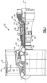
- FIG. 1 schematically illustrates a gas turbine engine 20.
- the gas turbine engine 20 is disclosed herein as a two-spool turbofan that generally incorporates a fan section 22, a compressor section 24, a combustor section 26 and a turbine section 28.
- the fan section 22 drives air along a bypass flow path B in a bypass duct defined within a nacelle 15, and also drives air along a core flow path C for compression and communication into the combustor section 26 then expansion through the turbine section 28.
- FIG. 1 schematically illustrates a gas turbine engine 20.
- the gas turbine engine 20 is disclosed herein as a two-spool turbofan that generally incorporates a fan section 22, a compressor section 24, a combustor section 26 and a turbine section 28.
- the fan section 22 drives air along a bypass flow path B in a bypass duct defined within a nacelle 15, and also drives air along a core flow path C for compression and communication into the combustor section 26 then expansion through the turbine section 28.
- FIG. 1 schematic
- the exemplary engine 20 generally includes a low speed spool 30 and a high speed spool 32 mounted for rotation about an engine central longitudinal axis A relative to an engine static structure 36 via several bearing systems 38. It should be understood that various bearing systems 38 at various locations may alternatively or additionally be provided, and the location of bearing systems 38 may be varied as appropriate to the application.
- the low speed spool 30 generally includes an inner shaft 40 that interconnects, a first (or low) pressure compressor 44 and a first (or low) pressure turbine 46.
- the inner shaft 40 is connected to the fan 42 through a speed change mechanism, which in exemplary gas turbine engine 20 is illustrated as a geared architecture 48 to drive a fan 42 at a lower speed than the low speed spool 30.
- the high speed spool 32 includes an outer shaft 50 that interconnects a second (or high) pressure compressor 52 and a second (or high) pressure turbine 54.
- a combustor 56 is arranged in exemplary gas turbine 20 between the high pressure compressor 52 and the high pressure turbine 54.
- a mid-turbine frame 57 of the engine static structure 36 may be arranged generally between the high pressure turbine 54 and the low pressure turbine 46.
- the mid-turbine frame 57 further supports bearing systems 38 in the turbine section 28.
- the inner shaft 40 and the outer shaft 50 are concentric and rotate via bearing systems 38 about the engine central longitudinal axis A which is colline
- the core airflow is compressed by the low pressure compressor 44 then the high pressure compressor 52, mixed and burned with fuel in the combustor 56, then expanded over the high pressure turbine 54 and low pressure turbine 46.
- the mid-turbine frame 57 includes airfoils 59 which are in the core airflow path C.
- the turbines 46, 54 rotationally drive the respective low speed spool 30 and high speed spool 32 in response to the expansion.
- gear system 48 may be located aft of the low pressure compressor, or aft of the combustor section 26 or even aft of turbine section 28, and fan 42 may be positioned forward or aft of the location of gear system 48.
- the engine 20 in one example is a high-bypass geared aircraft engine.
- the engine 20 bypass ratio is greater than about 6:1, with an example embodiment being greater than about 10:1
- the geared architecture 48 is an epicyclic gear train, such as a planetary gear system or other gear system, with a gear reduction ratio of greater than about 2.3:1 and the low pressure turbine 46 has a pressure ratio that is greater than about 5:1.
- the engine 20 bypass ratio is greater than about ten 10:1
- the fan diameter is significantly larger than that of the low pressure compressor 44
- the low pressure turbine 46 has a pressure ratio that is greater than about 5:1.
- the low pressure turbine 46 pressure ratio is pressure measured prior to the inlet of low pressure turbine 46 as related to the pressure at the outlet of the low pressure turbine 46 prior to an exhaust nozzle.
- the geared architecture 48 may be an epicycle gear train, such as a planetary gear system or other gear system, with a gear reduction ratio of greater than about 2.3:1 and less than about 5:1. It should be understood, however, that the above parameters are only exemplary of one embodiment of a geared architecture engine and that the present invention is applicable to other gas turbine engines including but not limited to direct drive turbofans, low bypass engines, and multi-stage fan engines.
- the fan section 22 of the engine 20 is designed for a particular flight condition -- typically cruise at about 0.8 Mach and about 35,000 feet (10,668 meters).
- the flight condition of 0.8 Mach and 35,000 ft (10,668 meters), with the engine at its best fuel consumption - also known as "bucket cruise Thrust Specific Fuel Consumption ('TSFC')" - is the industry standard parameter of lbm of fuel being burned divided by lbf of thrust the engine produces at that minimum point.
- "Low fan pressure ratio” is the pressure ratio across the fan blade alone, without a Fan Exit Guide Vane (“FEGV”) system.
- the low fan pressure ratio as disclosed herein according to one non-limiting embodiment is less than about 1.45:1.
- the "Low corrected fan tip speed” as disclosed herein according to one non-limiting embodiment is less than about 1150 ft / second (350.5 meters/second).
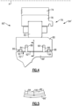
- Figure 2 is a schematic cross-sectional view of a portion of the engine 20 including a squeeze film damper 60.
- the squeeze film damper 60 is configured to reduce vibrations and other instabilities in rotating shafts, such as the low speed spool 30 and/or the high speed spool 32, within the engine 20.
- Each shaft of the engine 20 may include one or more of the squeeze film dampers 60.
- the squeeze film dampers 60 may be spaced-apart from one another along the length of the respective shaft.
- the squeeze film dampers 60 may be arranged adjacent bearings rotationally supporting the shafts in the engine 20.
- the squeeze film dampers 60 may be located in or adjacent bearing compartments. This disclosure is not limited to any particular location of the squeeze film dampers, however.
- the squeeze film damper 60 includes a cavity 62 radially (i.e., in a direction normal to the engine central longitudinal axis A) between a rotating assembly 64 and a static housing 66.
- the cavity 62 includes a relatively thin film of lubricant, which in one example is oil. In another example, the lubricant is an air-oil mixture.
- the cavity 62 is fluidly coupled to a source of lubricant.
- the cavity 62 may be fluidly coupled with a bearing compartment or arranged in a bearing compartment, and receive a supply of lubricant from the bearing compartment.
- the rotating assembly 64 which may include the low speed spool 30 and/or the high speed spool 32 along with a bearing, rotates about its central axis X, which ideally is concentric with the engine central longitudinal axis A. Not all elements in the rotating assembly 64 are rotatable in all examples. However, during operating of the engine 20, the axis X may become slightly spaced-apart from the engine central longitudinal axis A at the location of the squeeze film damper 60. In such cases the axis X of the rotating assembly 64 orbits about the engine central longitudinal axis A. The path of orbit may be circular or non-circular.
- the rotating assembly 64 rotates in the direction Z about the axis X.
- the Z direction is a counter-clockwise direction.
- the axis X is spaced-apart from the engine central longitudinal axis A in the left-hand direction.
- the rotating assembly 64 creates a leading high pressure wave of lubricant at location 68.
- the rotating assembly 64 causes lubricant to flow from the cavity 62 into a reservoir 70 via an opening, which here is a single orifice 72, in the static housing 66.
- the reservoir 70 is an enclosed space which is fluidly coupled to the cavity 62, and is configured to hold lubricant therein.
- the reservoir 70 is radially outside the cavity 62 and the housing 66, and the orifice 72 extends radially outward from a bottom-most location of the cavity 62, sometimes referred to as bottom dead center (BDC).
- BDC bottom dead center
- the reservoir 70 is passively fluidly coupled to the cavity 62, meaning lubricant is free to flow in and out of the reservoir 70.
- the rotating assembly 64 approaches the orifice 72, the leading high pressure wave forces lubricant into the reservoir 70.
- the rotating assembly 64 also creates a trailing low pressure wake of lubricant, at location 73 in Figure 3 , for example. As the rotating assembly 64 rotates past the orifice 72 the trailing low pressure wake causes lubricant to flow from the reservoir 70 into the cavity 62.
- the low pressure wake causes the cavity 62 to ingest (i.e., draw in) the same lubricant already in the cavity, rather than ingesting air, for example, which could lead to an undesirable amount of air in the lubricant, which in turn could make the squeeze film damper 60 less effective.
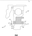
- Figure 4 is a partial cross-sectional view of a portion of the engine 20 and illustrates another example squeeze film damper 60' in more detail. It should be understood that the elements shown in partial cross-sectional views in this disclosure generally extend circumferentially about the entire engine central longitudinal axis A.
- the squeeze film damper 60' includes many of the same components as the squeeze film damper 60, namely a cavity 62' radially between a rotating assembly 64' and a static housing 66'.
- the rotating assembly 64' includes a shaft 74, which may be the low speed spool 30 or the high speed spool 34 or a spool associated with the fan section 22, and a bearing 76 radially inside the static housing 66' and radially outside the shaft 74.
- the bearing 76 includes an inner race 78 mounted to the shaft 74 either directly or indirectly.
- shaft 74 in Figure 4 may be representative of a component configured to directly couple to the low speed or high speed spool, in some examples.
- the inner race 78 is configured to rotate with the shaft 74, in this example.
- the bearing 76 further includes an outer race 80, and a plurality of rolling elements 82 between the inner and outer races 78, 80.
- the static housing 66' provides a radially outer boundary of the cavity 62' and the outer race 80 provides a radially inner boundary of the cavity 62'.
- the cavity 62' is axially bound by first and second cavity seals 84, 86, in this example.
- the first and second cavity seals 84, 86 are axially spaced-apart from one another along the engine central longitudinal axis A.
- the first and second cavity seals 84, 86 are received in a respective channel 88, 90 in the outer race 80 and extend radially outward toward, and directly contact, the static housing 66'.
- the first and second cavity seals 84, 86 extend circumferentially about the entire engine central longitudinal axis A.
- the reservoir 70' is axially spaced-apart from the cavity 62'. Further, the reservoir 70' includes a first portion 92 on a first axial side of the cavity 62' and a second portion 94 on a second axial side of the cavity 62' opposite the first axial side. The first and second axial sides are fore and aft sides, respectively, in this example.
- the first portion 92 is between a first reservoir seal 96 and the first cavity seal 84
- the second portion 94 is between a second reservoir seal 98 and the second cavity seal 86.
- the reservoir and cavity seals may be piston rings or elastomeric seals, as examples.
- first and second portions 92, 94 are illustrated in Figure 4 , in some example arrangements there is only one of the first and second portions 92, 94.
- the reservoir 70' is either axially forward or axially aft of the cavity 62', but not both, as in Figure 4 .
- the reservoir 70' may extend about the entire circumference of the engine central longitudinal axis A. In other examples, the reservoir 70' is only arranged adjacent the bottom-most location of the cavity 62'.
- the first and second portions 92, 94 are substantially equally sized in Figure 4 , the first and second portions 92, 94 could be different sizes.
- the first and second cavity seals 84, 86 each include at least one opening functioning substantially the same as the orifice 72 in Figure 3 , namely by permitting lubricant to passively flow between the respective first and second portions 92, 94 of the reservoir 70' and the cavity 62'.
- An example opening 100 in the first cavity seal 84 is illustrated in Figure 5 .
- the opening 100 is provided by a notch in a radially outer surface of the first cavity seal 84.
- the opening 100 extends axially through the entire first cavity seal 84 to provide a path between the cavity 62' and the reservoir 70'.
- the opening 100 is arranged at a bottom-most location of the first cavity seal 84 in this example.
- the opening 100 could be arranged at different locations and does not need to be provided by a notch in all examples.
- the opening 100 could be provided by a gap between ends of a seal, for example.
- the second cavity seal 86 can include an opening similar to the opening 100.
- the first and second cavity seals 84, 86 may include a plurality of openings fluidly coupling the cavity 62' and the reservoir 70'.
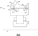
- Figure 6 and 7 illustrate example ports fluidly coupled to the cavity 62'.
- the ports are fluidly coupled to the top-most location of the reservoir 70', namely the first and second portions 92, 94.
- the static housing 66' includes first and second oil pools 102, 104 formed in a top-most surface of the static housing 66' and are open facing a radially outward direction.
- the first and second oil pools 102, 104 are fluidly coupled to respective first and second portions 92, 94 of the reservoir 70' by respective passages 106, 108.
- excess lubricant fills the first and second portions 92, 94 and may flow through the passages 106, 108 to at least partially fill the first and second oil pools 102, 104.
- lubricant enters a bearing compartment. This configuration ensures air is substantially expunged from the lubricant within the cavity 62'.
- FIG. 7 An alternate arrangement is shown in Figure 7 .
- a single oil pool 110 is formed in the static housing 66'.
- the oil pool 110 is open facing an axial direction.
- the oil pool 110 is fluidly coupled to respective first and second portions 92, 94 of the reservoir 70' by respective passages 112, 114.
- the passages 112, 114 are radially-extending.
- the passages 112, 114 could be inclined relative to the radial direction, however, in a manner similar to the passages 106, 108 in Figure 6 .
- the oil pool 110 is closed at an axial end by a drain cap 116, which includes at least one hole, and which is threaded or welded in, as examples.
- the oil pool 110 functions substantially similar to the oil pools 102, 104, namely by ensuring air is substantially expunged from the cavity 62' during filling.
- Figure 8 is a partial cross-sectional view of a portion of the engine 20 and illustrates another example squeeze film damper 60" in more detail.
- the reservoir 70" includes first and second portions 92", 94" which are essentially collection areas or basins adjacent a bottom-most location of the rotating assembly 64".
- the first and second portions 92", 94" are bound at a radially inner location by the static housing 66". Lubricant collects and tends to remain in the first and second portions 92", 94" by virtue of their position at the bottom-most location of the rotating assembly 64".
- the static housing 66" and/or a structure 116 adjacent the outer race 80" may include projections such as tabs or flanges configured to radially cover the first and second portions 92" and 94" on an opposite side of the static housing 66", as shown in Figure 9 .
- the structure 116 could be integral with the outer race 80".
- the structure 116 includes a projection 118 projecting from the structure 116 and abutting another structure projecting radially outwardly from the static housing to provide a radially inner boundary of the first portion 92" and the static housing includes a projection 120 providing a radially inner boundary of the second portion 94".
- the projection 120 in particular, includes a radially-extending component 122 providing an axially aft boundary of the second portion 94" and an axially-extending component 124 providing the radially inner boundary.
- Figures 10 and 11 Yet another example arrangement is illustrated in Figures 10 and 11 .
- the static housing 66′′′ includes a groove 126 in a radially inner face thereof receiving a ring 128 to provide an axially fore boundary of the first portion 92'".
- the ring 128 projects radially outward from the groove 126 and contacts the structure 116', which is directly connected to the outer race 80"'.
- the second portion 94′′′ is axially bound by a radial projection 130 projecting radially from, and formed integrally with, the static housing 66′′′ and contacting the structure 116'.
- the ring 128 is a split ring, in this example.
- the ring 128 includes a groove 132 defined between a first end 134 of the ring 128 and a second end 136 of the ring 128.
- the first and second ends 134, 136 are spaced circumferentially apart from one another.
- the first and second ends 134, 136 are defined by faces which are parallel to one another and which extend in directions non-parallel with the engine central longitudinal axis A.
- the groove 132 increases the ease of installing the ring 128 by permitting expansion of the ring 128 during installation.
- the ring 128 also retracts after installation to provide a boundary of the first portion 92'".
Landscapes
- Engineering & Computer Science (AREA)
- General Engineering & Computer Science (AREA)
- Mechanical Engineering (AREA)
- Chemical & Material Sciences (AREA)
- Combustion & Propulsion (AREA)
- Physics & Mathematics (AREA)
- Fluid Mechanics (AREA)
- Acoustics & Sound (AREA)
- Aviation & Aerospace Engineering (AREA)
- Rolling Contact Bearings (AREA)
Claims (15)
- Moteur à turbine à gaz (20), comprenant :un arbre (74) configuré pour tourner pendant le fonctionnement du moteur à turbine à gaz (20) ; etun amortisseur à film comprimé (60') radialement à l'extérieur de l'arbre (74), l'amortisseur à film comprimé (60') comportant une cavité (62') comportant un film de lubrifiant axialement entre le premier et le second joints d'étanchéité de cavité (84, 86), et comportant en outre un réservoir (70') couplé fluidiquement à la cavité (62'),caractérisé en ce quele réservoir (70') est couplé fluidiquement de manière passive à la cavité (62') de sorte que le lubrifiant peut librement s'écouler dans et hors du réservoir (70') pendant le fonctionnement du moteur à turbine à gaz (20) ; etau moins l'un des premier et second joints d'étanchéité de cavité (84, 86) comporte une ouverture (100) couplant fluidiquement la cavité (62') au réservoir (70') et permettant au lubrifiant de s'écouler dans et hors du réservoir (70') à travers l'ouverture (100) .
- Moteur à turbine à gaz (20) selon la revendication 1, dans lequel le réservoir (70) est espacé axialement de la cavité (62) .
- Moteur à turbine à gaz (20) selon la revendication 1, dans lequel l'ouverture (100) s'étend radialement vers l'extérieur à partir d'un emplacement le plus bas de la cavité (62').
- Moteur à turbine à gaz (20) selon la revendication 1 ou 2, dans lequel l'ouverture (100) est adjacente à un emplacement le plus bas de la cavité (62').
- Moteur à turbine à gaz (20) selon l'une quelconque des revendications 1 à 4, dans lequel le réservoir (70') comporte une première partie (92) sur un premier côté axial de la cavité (62') et une seconde partie sur un second côté axial de la cavité (62') opposé au premier côté axial, et éventuellement la première partie (92) est délimitée au moins en partie par le premier joint d'étanchéité de cavité (84) et soit un premier joint d'étanchéité de réservoir (96), soit un anneau, ou une saillie (118), et
la seconde partie est délimitée au moins en partie par le second joint d'étanchéité de cavité (86) et soit par un second joint d'étanchéité de réservoir (98), soit par une saillie (118). - Moteur à turbine à gaz (20) selon l'une quelconque des revendications 1 à 5, comprenant en outre :un boîtier (66) ; etun roulement (76) radialement à l'intérieur du boîtier (66) et radialement à l'extérieur de l'arbre (74), le roulement (76) comportant une bague intérieure (78) montée sur l'arbre (74), une bague extérieure (80) et une pluralité d'éléments roulants (82) entre les bagues intérieur et extérieur (78, 80).
- Moteur à turbine à gaz (20) selon la revendication 6, dans lequel le boîtier (66') fournit une limite radialement extérieure de la cavité (62') et la bague extérieure (80) fournit une limite radialement intérieure de la cavité (62').
- Moteur à turbine à gaz (20) selon l'une quelconque des revendications 1 à 7, comprenant en outre une source de lubrifiant couplée fluidiquement à la cavité (62).
- Moteur à turbine à gaz (20) selon la revendication 8, dans lequel le lubrifiant est de l'huile ou un mélange air-huile.
- Moteur à turbine à gaz (20) selon l'une quelconque des revendications 1 à 9, dans lequel un orifice est couplé fluidiquement à un emplacement le plus haut du réservoir (70), et éventuellement l'orifice comporte un bain d'huile (110).
- Moteur à turbine à gaz (20) selon l'une quelconque des revendications 1 à 10, dans lequel l'arbre (74) est l'un d'un corps à basse vitesse (30) et d'un corps à grande vitesse (32).
- Moteur à turbine à gaz (20) selon l'une quelconque des revendications 1 à 11, dans lequel l'amortisseur à film comprimé (60) est l'un d'une pluralité d'amortisseurs à film comprimé (60) disposés le long de l'arbre (74).
- Procédé de fonctionnement d'un moteur à turbine à gaz (20) selon l'une quelconque des revendications 1 à 12, dans lequel le procédé comprend le fait de permettre au lubrifiant de s'écouler passivement entre une cavité (62') de l'amortisseur à film comprimé et le réservoir pendant le fonctionnement du moteur à turbine à gaz (20) ;
caractérisé en ce que
le lubrifiant peut librement s'écouler dans et hors du réservoir (70) pendant le fonctionnement du moteur à turbine à gaz (20) à travers une ouverture (100) dans un joint d'étanchéité (84, 86) entre le réservoir (70) et la cavité (62). - Procédé selon la revendication 13, dans lequel :la cavité (62) est radialement située entre un ensemble rotatif (64) et un boîtier statique (66), etl'ensemble rotatif (64) tourne autour d'un axe espacé d'un axe longitudinal central du moteur à turbine à gaz (20) pendant le fonctionnement du moteur à turbine à gaz (20).
- Procédé selon la revendication 14, dans lequel l'ensemble rotatif (64) crée une onde haute pression avant qui amène le lubrifiant à s'écouler de la cavité (62) dans le réservoir (70), et un sillage arrière basse pression qui amène le lubrifiant à s'écouler du réservoir (70) dans la cavité (62).
Applications Claiming Priority (1)
| Application Number | Priority Date | Filing Date | Title |
|---|---|---|---|
| US16/736,281 US11306657B2 (en) | 2020-01-07 | 2020-01-07 | Gas turbine engine including squeeze film damper with reservoir |
Publications (2)
| Publication Number | Publication Date |
|---|---|
| EP3848559A1 EP3848559A1 (fr) | 2021-07-14 |
| EP3848559B1 true EP3848559B1 (fr) | 2024-02-28 |
Family
ID=74103954
Family Applications (1)
| Application Number | Title | Priority Date | Filing Date |
|---|---|---|---|
| EP21150215.8A Active EP3848559B1 (fr) | 2020-01-07 | 2021-01-05 | Moteur à turbine à gaz comportant un amortisseur à film comprimé avec réservoir |
Country Status (2)
| Country | Link |
|---|---|
| US (1) | US11306657B2 (fr) |
| EP (1) | EP3848559B1 (fr) |
Cited By (1)
| Publication number | Priority date | Publication date | Assignee | Title |
|---|---|---|---|---|
| EP4711586A1 (fr) * | 2024-09-06 | 2026-03-18 | Pratt & Whitney Canada Corp. | Système anti-rotation et de retenue de palier pour un moteur à turbine à gaz |
Family Cites Families (13)
| Publication number | Priority date | Publication date | Assignee | Title |
|---|---|---|---|---|
| US4669893A (en) * | 1986-02-18 | 1987-06-02 | United Technologies Corporation | Annular oil damper arrangement |
| US4782919A (en) * | 1987-12-21 | 1988-11-08 | United Technologies Corporation | Supply system for oil dampers |
| US5067825A (en) * | 1990-06-18 | 1991-11-26 | Vance John M | Aircraft engine rotor squeeze film damper |
| US5071262A (en) | 1990-11-05 | 1991-12-10 | General Electric Company | Squeeze film damper fluid control |
| US5197807A (en) | 1991-01-08 | 1993-03-30 | General Electric Company | Squeeze film damper seal ring |
| US5149206A (en) | 1991-04-17 | 1992-09-22 | General Electric Company | Hydraulic shaft damper pressure control |
| US5207511A (en) | 1991-07-22 | 1993-05-04 | General Electric Company | Squeeze film damper oil control |
| US5344239A (en) * | 1992-11-25 | 1994-09-06 | General Electric Company | Squeeze film bearing damper with annular end plenums |
| US7665897B2 (en) | 2006-01-17 | 2010-02-23 | Honeywell International Inc. | Squeeze film damper using low pressure oil |
| US10233778B2 (en) | 2016-06-03 | 2019-03-19 | United Technologies Corporation | Circumferential plenum for oil damper |
| US10094420B1 (en) * | 2017-03-27 | 2018-10-09 | United Technologies Corporation | Squeeze film damper with low pressure reservoirs |
| FR3069571B1 (fr) | 2017-07-26 | 2019-08-30 | Safran Aircraft Engines | Systeme a compression de film fluide et machine tournante comprenant un tel systeme |
| US10495144B1 (en) * | 2018-05-25 | 2019-12-03 | Borgwarner Inc. | Single-row ball bearing with integrated squeeze-film damper |
-
2020
- 2020-01-07 US US16/736,281 patent/US11306657B2/en active Active
-
2021
- 2021-01-05 EP EP21150215.8A patent/EP3848559B1/fr active Active
Cited By (1)
| Publication number | Priority date | Publication date | Assignee | Title |
|---|---|---|---|---|
| EP4711586A1 (fr) * | 2024-09-06 | 2026-03-18 | Pratt & Whitney Canada Corp. | Système anti-rotation et de retenue de palier pour un moteur à turbine à gaz |
Also Published As
| Publication number | Publication date |
|---|---|
| US20210207532A1 (en) | 2021-07-08 |
| EP3848559A1 (fr) | 2021-07-14 |
| US11306657B2 (en) | 2022-04-19 |
Similar Documents
| Publication | Publication Date | Title |
|---|---|---|
| EP2809908B1 (fr) | Système tampon de carter intermédiaire de turbine | |
| EP3620608B1 (fr) | Agencement de palier ayant un amortisseur auto-pressurisé à éspace axial réduit et procédé associé de maintien de pression dans ledit amortisseur | |
| EP3702586B1 (fr) | Moteur à turbine à gaz comprenant une plaque d'étanchéité fournissant une zone de contact adjacente de refroidissement accrue | |
| US9546560B2 (en) | Compact double grounded mechanical carbon seal | |
| EP3318722B1 (fr) | Ensemble d'étanchéité pour un composant rotatif | |
| EP3524797A2 (fr) | Plaque de retenue pilotée pour un joint de face | |
| EP3382230B1 (fr) | Amortisseur à film d'huile comportant des réservoirs à faible pression et methode correspondante | |
| EP4700258A2 (fr) | Agencement de joint d'étanchéité à face à force et pression réduites | |
| US11725694B2 (en) | Seal runner with deflector and catcher for gas turbine engine | |
| EP3401514B1 (fr) | Anneau structurel d'amortisseur fluidique et procédé d'amortissement fluidique associé | |
| EP4012162B1 (fr) | Manchon rotatif contrôlant le jeu de l'ensemble d'étanchéité d'une turbine à gaz | |
| EP3848559A1 (fr) | Moteur à turbine à gaz comportant un amortisseur à film comprimé avec réservoir | |
| EP3943776B1 (fr) | Amortisseur à film d'huile à auto-pressurisation | |
| EP3816472B1 (fr) | Faisceau incurvé axialement rigide avec amortisseur d'huile | |
| EP3835606B1 (fr) | Ressort de centrage incurvé pour un palier de butée | |
| EP3680454B1 (fr) | Système de tampon pour moteur à turbine à gaz | |
| US11313471B2 (en) | Shrouded aircraft engine seal carrier | |
| EP3812555B1 (fr) | Agencement de retour d'huile pour moteur à turbine à gaz | |
| EP3741962B1 (fr) | Couvercle pour arbre rotatif de moteur à turbine à gaz | |
| US12392251B2 (en) | Diametrically expandable/collapsible piston seal |
Legal Events
| Date | Code | Title | Description |
|---|---|---|---|
| PUAI | Public reference made under article 153(3) epc to a published international application that has entered the european phase |
Free format text: ORIGINAL CODE: 0009012 |
|
| STAA | Information on the status of an ep patent application or granted ep patent |
Free format text: STATUS: THE APPLICATION HAS BEEN PUBLISHED |
|
| AK | Designated contracting states |
Kind code of ref document: A1 Designated state(s): AL AT BE BG CH CY CZ DE DK EE ES FI FR GB GR HR HU IE IS IT LI LT LU LV MC MK MT NL NO PL PT RO RS SE SI SK SM TR |
|
| STAA | Information on the status of an ep patent application or granted ep patent |
Free format text: STATUS: REQUEST FOR EXAMINATION WAS MADE |
|
| 17P | Request for examination filed |
Effective date: 20220112 |
|
| RBV | Designated contracting states (corrected) |
Designated state(s): AL AT BE BG CH CY CZ DE DK EE ES FI FR GB GR HR HU IE IS IT LI LT LU LV MC MK MT NL NO PL PT RO RS SE SI SK SM TR |
|
| GRAP | Despatch of communication of intention to grant a patent |
Free format text: ORIGINAL CODE: EPIDOSNIGR1 |
|
| STAA | Information on the status of an ep patent application or granted ep patent |
Free format text: STATUS: GRANT OF PATENT IS INTENDED |
|
| INTG | Intention to grant announced |
Effective date: 20230911 |
|
| RIN1 | Information on inventor provided before grant (corrected) |
Inventor name: BORATGIS, ERNEST Inventor name: AMADOR, ARMANDO |
|
| RAP3 | Party data changed (applicant data changed or rights of an application transferred) |
Owner name: RTX CORPORATION |
|
| GRAS | Grant fee paid |
Free format text: ORIGINAL CODE: EPIDOSNIGR3 |
|
| GRAA | (expected) grant |
Free format text: ORIGINAL CODE: 0009210 |
|
| STAA | Information on the status of an ep patent application or granted ep patent |
Free format text: STATUS: THE PATENT HAS BEEN GRANTED |
|
| AK | Designated contracting states |
Kind code of ref document: B1 Designated state(s): AL AT BE BG CH CY CZ DE DK EE ES FI FR GB GR HR HU IE IS IT LI LT LU LV MC MK MT NL NO PL PT RO RS SE SI SK SM TR |
|
| REG | Reference to a national code |
Ref country code: GB Ref legal event code: FG4D |
|
| REG | Reference to a national code |
Ref country code: CH Ref legal event code: EP |
|
| REG | Reference to a national code |
Ref country code: DE Ref legal event code: R096 Ref document number: 602021009697 Country of ref document: DE |
|
| REG | Reference to a national code |
Ref country code: IE Ref legal event code: FG4D |
|
| REG | Reference to a national code |
Ref country code: LT Ref legal event code: MG9D |
|
| PG25 | Lapsed in a contracting state [announced via postgrant information from national office to epo] |
Ref country code: IS Free format text: LAPSE BECAUSE OF FAILURE TO SUBMIT A TRANSLATION OF THE DESCRIPTION OR TO PAY THE FEE WITHIN THE PRESCRIBED TIME-LIMIT Effective date: 20240628 |
|
| REG | Reference to a national code |
Ref country code: NL Ref legal event code: MP Effective date: 20240228 |
|
| PG25 | Lapsed in a contracting state [announced via postgrant information from national office to epo] |
Ref country code: LT Free format text: LAPSE BECAUSE OF FAILURE TO SUBMIT A TRANSLATION OF THE DESCRIPTION OR TO PAY THE FEE WITHIN THE PRESCRIBED TIME-LIMIT Effective date: 20240228 |
|
| PG25 | Lapsed in a contracting state [announced via postgrant information from national office to epo] |
Ref country code: GR Free format text: LAPSE BECAUSE OF FAILURE TO SUBMIT A TRANSLATION OF THE DESCRIPTION OR TO PAY THE FEE WITHIN THE PRESCRIBED TIME-LIMIT Effective date: 20240529 |
|
| PG25 | Lapsed in a contracting state [announced via postgrant information from national office to epo] |
Ref country code: RS Free format text: LAPSE BECAUSE OF FAILURE TO SUBMIT A TRANSLATION OF THE DESCRIPTION OR TO PAY THE FEE WITHIN THE PRESCRIBED TIME-LIMIT Effective date: 20240528 Ref country code: HR Free format text: LAPSE BECAUSE OF FAILURE TO SUBMIT A TRANSLATION OF THE DESCRIPTION OR TO PAY THE FEE WITHIN THE PRESCRIBED TIME-LIMIT Effective date: 20240228 Ref country code: NL Free format text: LAPSE BECAUSE OF FAILURE TO SUBMIT A TRANSLATION OF THE DESCRIPTION OR TO PAY THE FEE WITHIN THE PRESCRIBED TIME-LIMIT Effective date: 20240228 |
|
| PG25 | Lapsed in a contracting state [announced via postgrant information from national office to epo] |
Ref country code: ES Free format text: LAPSE BECAUSE OF FAILURE TO SUBMIT A TRANSLATION OF THE DESCRIPTION OR TO PAY THE FEE WITHIN THE PRESCRIBED TIME-LIMIT Effective date: 20240228 |
|
| PG25 | Lapsed in a contracting state [announced via postgrant information from national office to epo] |
Ref country code: RS Free format text: LAPSE BECAUSE OF FAILURE TO SUBMIT A TRANSLATION OF THE DESCRIPTION OR TO PAY THE FEE WITHIN THE PRESCRIBED TIME-LIMIT Effective date: 20240528 Ref country code: NO Free format text: LAPSE BECAUSE OF FAILURE TO SUBMIT A TRANSLATION OF THE DESCRIPTION OR TO PAY THE FEE WITHIN THE PRESCRIBED TIME-LIMIT Effective date: 20240528 Ref country code: NL Free format text: LAPSE BECAUSE OF FAILURE TO SUBMIT A TRANSLATION OF THE DESCRIPTION OR TO PAY THE FEE WITHIN THE PRESCRIBED TIME-LIMIT Effective date: 20240228 Ref country code: LT Free format text: LAPSE BECAUSE OF FAILURE TO SUBMIT A TRANSLATION OF THE DESCRIPTION OR TO PAY THE FEE WITHIN THE PRESCRIBED TIME-LIMIT Effective date: 20240228 Ref country code: IS Free format text: LAPSE BECAUSE OF FAILURE TO SUBMIT A TRANSLATION OF THE DESCRIPTION OR TO PAY THE FEE WITHIN THE PRESCRIBED TIME-LIMIT Effective date: 20240628 Ref country code: HR Free format text: LAPSE BECAUSE OF FAILURE TO SUBMIT A TRANSLATION OF THE DESCRIPTION OR TO PAY THE FEE WITHIN THE PRESCRIBED TIME-LIMIT Effective date: 20240228 Ref country code: GR Free format text: LAPSE BECAUSE OF FAILURE TO SUBMIT A TRANSLATION OF THE DESCRIPTION OR TO PAY THE FEE WITHIN THE PRESCRIBED TIME-LIMIT Effective date: 20240529 Ref country code: FI Free format text: LAPSE BECAUSE OF FAILURE TO SUBMIT A TRANSLATION OF THE DESCRIPTION OR TO PAY THE FEE WITHIN THE PRESCRIBED TIME-LIMIT Effective date: 20240228 Ref country code: ES Free format text: LAPSE BECAUSE OF FAILURE TO SUBMIT A TRANSLATION OF THE DESCRIPTION OR TO PAY THE FEE WITHIN THE PRESCRIBED TIME-LIMIT Effective date: 20240228 Ref country code: BG Free format text: LAPSE BECAUSE OF FAILURE TO SUBMIT A TRANSLATION OF THE DESCRIPTION OR TO PAY THE FEE WITHIN THE PRESCRIBED TIME-LIMIT Effective date: 20240228 |
|
| PG25 | Lapsed in a contracting state [announced via postgrant information from national office to epo] |
Ref country code: PL Free format text: LAPSE BECAUSE OF FAILURE TO SUBMIT A TRANSLATION OF THE DESCRIPTION OR TO PAY THE FEE WITHIN THE PRESCRIBED TIME-LIMIT Effective date: 20240228 Ref country code: PT Free format text: LAPSE BECAUSE OF FAILURE TO SUBMIT A TRANSLATION OF THE DESCRIPTION OR TO PAY THE FEE WITHIN THE PRESCRIBED TIME-LIMIT Effective date: 20240628 |
|
| REG | Reference to a national code |
Ref country code: AT Ref legal event code: MK05 Ref document number: 1661428 Country of ref document: AT Kind code of ref document: T Effective date: 20240228 |
|
| PG25 | Lapsed in a contracting state [announced via postgrant information from national office to epo] |
Ref country code: SE Free format text: LAPSE BECAUSE OF FAILURE TO SUBMIT A TRANSLATION OF THE DESCRIPTION OR TO PAY THE FEE WITHIN THE PRESCRIBED TIME-LIMIT Effective date: 20240228 Ref country code: PT Free format text: LAPSE BECAUSE OF FAILURE TO SUBMIT A TRANSLATION OF THE DESCRIPTION OR TO PAY THE FEE WITHIN THE PRESCRIBED TIME-LIMIT Effective date: 20240628 Ref country code: PL Free format text: LAPSE BECAUSE OF FAILURE TO SUBMIT A TRANSLATION OF THE DESCRIPTION OR TO PAY THE FEE WITHIN THE PRESCRIBED TIME-LIMIT Effective date: 20240228 Ref country code: LV Free format text: LAPSE BECAUSE OF FAILURE TO SUBMIT A TRANSLATION OF THE DESCRIPTION OR TO PAY THE FEE WITHIN THE PRESCRIBED TIME-LIMIT Effective date: 20240228 |
|
| PG25 | Lapsed in a contracting state [announced via postgrant information from national office to epo] |
Ref country code: DK Free format text: LAPSE BECAUSE OF FAILURE TO SUBMIT A TRANSLATION OF THE DESCRIPTION OR TO PAY THE FEE WITHIN THE PRESCRIBED TIME-LIMIT Effective date: 20240228 |
|
| PG25 | Lapsed in a contracting state [announced via postgrant information from national office to epo] |
Ref country code: SM Free format text: LAPSE BECAUSE OF FAILURE TO SUBMIT A TRANSLATION OF THE DESCRIPTION OR TO PAY THE FEE WITHIN THE PRESCRIBED TIME-LIMIT Effective date: 20240228 |
|
| PG25 | Lapsed in a contracting state [announced via postgrant information from national office to epo] |
Ref country code: EE Free format text: LAPSE BECAUSE OF FAILURE TO SUBMIT A TRANSLATION OF THE DESCRIPTION OR TO PAY THE FEE WITHIN THE PRESCRIBED TIME-LIMIT Effective date: 20240228 Ref country code: CZ Free format text: LAPSE BECAUSE OF FAILURE TO SUBMIT A TRANSLATION OF THE DESCRIPTION OR TO PAY THE FEE WITHIN THE PRESCRIBED TIME-LIMIT Effective date: 20240228 |
|
| PG25 | Lapsed in a contracting state [announced via postgrant information from national office to epo] |
Ref country code: AT Free format text: LAPSE BECAUSE OF FAILURE TO SUBMIT A TRANSLATION OF THE DESCRIPTION OR TO PAY THE FEE WITHIN THE PRESCRIBED TIME-LIMIT Effective date: 20240228 |
|
| PG25 | Lapsed in a contracting state [announced via postgrant information from national office to epo] |
Ref country code: SK Free format text: LAPSE BECAUSE OF FAILURE TO SUBMIT A TRANSLATION OF THE DESCRIPTION OR TO PAY THE FEE WITHIN THE PRESCRIBED TIME-LIMIT Effective date: 20240228 |
|
| PG25 | Lapsed in a contracting state [announced via postgrant information from national office to epo] |
Ref country code: SM Free format text: LAPSE BECAUSE OF FAILURE TO SUBMIT A TRANSLATION OF THE DESCRIPTION OR TO PAY THE FEE WITHIN THE PRESCRIBED TIME-LIMIT Effective date: 20240228 Ref country code: SK Free format text: LAPSE BECAUSE OF FAILURE TO SUBMIT A TRANSLATION OF THE DESCRIPTION OR TO PAY THE FEE WITHIN THE PRESCRIBED TIME-LIMIT Effective date: 20240228 Ref country code: RO Free format text: LAPSE BECAUSE OF FAILURE TO SUBMIT A TRANSLATION OF THE DESCRIPTION OR TO PAY THE FEE WITHIN THE PRESCRIBED TIME-LIMIT Effective date: 20240228 Ref country code: EE Free format text: LAPSE BECAUSE OF FAILURE TO SUBMIT A TRANSLATION OF THE DESCRIPTION OR TO PAY THE FEE WITHIN THE PRESCRIBED TIME-LIMIT Effective date: 20240228 Ref country code: DK Free format text: LAPSE BECAUSE OF FAILURE TO SUBMIT A TRANSLATION OF THE DESCRIPTION OR TO PAY THE FEE WITHIN THE PRESCRIBED TIME-LIMIT Effective date: 20240228 Ref country code: CZ Free format text: LAPSE BECAUSE OF FAILURE TO SUBMIT A TRANSLATION OF THE DESCRIPTION OR TO PAY THE FEE WITHIN THE PRESCRIBED TIME-LIMIT Effective date: 20240228 Ref country code: AT Free format text: LAPSE BECAUSE OF FAILURE TO SUBMIT A TRANSLATION OF THE DESCRIPTION OR TO PAY THE FEE WITHIN THE PRESCRIBED TIME-LIMIT Effective date: 20240228 |
|
| REG | Reference to a national code |
Ref country code: DE Ref legal event code: R097 Ref document number: 602021009697 Country of ref document: DE |
|
| PG25 | Lapsed in a contracting state [announced via postgrant information from national office to epo] |
Ref country code: IT Free format text: LAPSE BECAUSE OF FAILURE TO SUBMIT A TRANSLATION OF THE DESCRIPTION OR TO PAY THE FEE WITHIN THE PRESCRIBED TIME-LIMIT Effective date: 20240228 |
|
| PG25 | Lapsed in a contracting state [announced via postgrant information from national office to epo] |
Ref country code: IT Free format text: LAPSE BECAUSE OF FAILURE TO SUBMIT A TRANSLATION OF THE DESCRIPTION OR TO PAY THE FEE WITHIN THE PRESCRIBED TIME-LIMIT Effective date: 20240228 |
|
| PLBE | No opposition filed within time limit |
Free format text: ORIGINAL CODE: 0009261 |
|
| STAA | Information on the status of an ep patent application or granted ep patent |
Free format text: STATUS: NO OPPOSITION FILED WITHIN TIME LIMIT |
|
| 26N | No opposition filed |
Effective date: 20241129 |
|
| PG25 | Lapsed in a contracting state [announced via postgrant information from national office to epo] |
Ref country code: SI Free format text: LAPSE BECAUSE OF FAILURE TO SUBMIT A TRANSLATION OF THE DESCRIPTION OR TO PAY THE FEE WITHIN THE PRESCRIBED TIME-LIMIT Effective date: 20240228 |
|
| REG | Reference to a national code |
Ref country code: CH Ref legal event code: PL |
|
| PG25 | Lapsed in a contracting state [announced via postgrant information from national office to epo] |
Ref country code: LU Free format text: LAPSE BECAUSE OF NON-PAYMENT OF DUE FEES Effective date: 20250105 Ref country code: MC Free format text: LAPSE BECAUSE OF FAILURE TO SUBMIT A TRANSLATION OF THE DESCRIPTION OR TO PAY THE FEE WITHIN THE PRESCRIBED TIME-LIMIT Effective date: 20240228 |
|
| PG25 | Lapsed in a contracting state [announced via postgrant information from national office to epo] |
Ref country code: BE Free format text: LAPSE BECAUSE OF NON-PAYMENT OF DUE FEES Effective date: 20250131 |
|
| PG25 | Lapsed in a contracting state [announced via postgrant information from national office to epo] |
Ref country code: CH Free format text: LAPSE BECAUSE OF NON-PAYMENT OF DUE FEES Effective date: 20250131 |
|
| REG | Reference to a national code |
Ref country code: BE Ref legal event code: MM Effective date: 20250131 |
|
| PGFP | Annual fee paid to national office [announced via postgrant information from national office to epo] |
Ref country code: GB Payment date: 20251220 Year of fee payment: 6 |
|
| PGFP | Annual fee paid to national office [announced via postgrant information from national office to epo] |
Ref country code: FR Payment date: 20251217 Year of fee payment: 6 |
|
| PG25 | Lapsed in a contracting state [announced via postgrant information from national office to epo] |
Ref country code: IE Free format text: LAPSE BECAUSE OF NON-PAYMENT OF DUE FEES Effective date: 20250105 |
|
| PGFP | Annual fee paid to national office [announced via postgrant information from national office to epo] |
Ref country code: DE Payment date: 20251217 Year of fee payment: 6 |