EP3848652A1 - Dispositif à cycle frigorifique - Google Patents
Dispositif à cycle frigorifique Download PDFInfo
- Publication number
- EP3848652A1 EP3848652A1 EP18932804.0A EP18932804A EP3848652A1 EP 3848652 A1 EP3848652 A1 EP 3848652A1 EP 18932804 A EP18932804 A EP 18932804A EP 3848652 A1 EP3848652 A1 EP 3848652A1
- Authority
- EP
- European Patent Office
- Prior art keywords
- refrigerant
- electric pump
- compressor
- route
- heat exchanger
- Prior art date
- Legal status (The legal status is an assumption and is not a legal conclusion. Google has not performed a legal analysis and makes no representation as to the accuracy of the status listed.)
- Withdrawn
Links
Images


Classifications
-
- F—MECHANICAL ENGINEERING; LIGHTING; HEATING; WEAPONS; BLASTING
- F25—REFRIGERATION OR COOLING; COMBINED HEATING AND REFRIGERATION SYSTEMS; HEAT PUMP SYSTEMS; MANUFACTURE OR STORAGE OF ICE; LIQUEFACTION SOLIDIFICATION OF GASES
- F25B—REFRIGERATION MACHINES, PLANTS OR SYSTEMS; COMBINED HEATING AND REFRIGERATION SYSTEMS; HEAT PUMP SYSTEMS
- F25B43/00—Arrangements for separating or purifying gases or liquids; Arrangements for vaporising the residuum of liquid refrigerant, e.g. by heat
- F25B43/006—Accumulators
-
- F—MECHANICAL ENGINEERING; LIGHTING; HEATING; WEAPONS; BLASTING
- F25—REFRIGERATION OR COOLING; COMBINED HEATING AND REFRIGERATION SYSTEMS; HEAT PUMP SYSTEMS; MANUFACTURE OR STORAGE OF ICE; LIQUEFACTION SOLIDIFICATION OF GASES
- F25B—REFRIGERATION MACHINES, PLANTS OR SYSTEMS; COMBINED HEATING AND REFRIGERATION SYSTEMS; HEAT PUMP SYSTEMS
- F25B43/00—Arrangements for separating or purifying gases or liquids; Arrangements for vaporising the residuum of liquid refrigerant, e.g. by heat
-
- F—MECHANICAL ENGINEERING; LIGHTING; HEATING; WEAPONS; BLASTING
- F25—REFRIGERATION OR COOLING; COMBINED HEATING AND REFRIGERATION SYSTEMS; HEAT PUMP SYSTEMS; MANUFACTURE OR STORAGE OF ICE; LIQUEFACTION SOLIDIFICATION OF GASES
- F25B—REFRIGERATION MACHINES, PLANTS OR SYSTEMS; COMBINED HEATING AND REFRIGERATION SYSTEMS; HEAT PUMP SYSTEMS
- F25B49/00—Arrangement or mounting of control or safety devices
- F25B49/02—Arrangement or mounting of control or safety devices for compression type machines, plants or systems
-
- F—MECHANICAL ENGINEERING; LIGHTING; HEATING; WEAPONS; BLASTING
- F25—REFRIGERATION OR COOLING; COMBINED HEATING AND REFRIGERATION SYSTEMS; HEAT PUMP SYSTEMS; MANUFACTURE OR STORAGE OF ICE; LIQUEFACTION SOLIDIFICATION OF GASES
- F25B—REFRIGERATION MACHINES, PLANTS OR SYSTEMS; COMBINED HEATING AND REFRIGERATION SYSTEMS; HEAT PUMP SYSTEMS
- F25B2313/00—Compression machines, plants or systems with reversible cycle not otherwise provided for
- F25B2313/023—Compression machines, plants or systems with reversible cycle not otherwise provided for using multiple indoor units
- F25B2313/0232—Compression machines, plants or systems with reversible cycle not otherwise provided for using multiple indoor units with bypasses
- F25B2313/02323—Compression machines, plants or systems with reversible cycle not otherwise provided for using multiple indoor units with bypasses during heating
-
- F—MECHANICAL ENGINEERING; LIGHTING; HEATING; WEAPONS; BLASTING
- F25—REFRIGERATION OR COOLING; COMBINED HEATING AND REFRIGERATION SYSTEMS; HEAT PUMP SYSTEMS; MANUFACTURE OR STORAGE OF ICE; LIQUEFACTION SOLIDIFICATION OF GASES
- F25B—REFRIGERATION MACHINES, PLANTS OR SYSTEMS; COMBINED HEATING AND REFRIGERATION SYSTEMS; HEAT PUMP SYSTEMS
- F25B2313/00—Compression machines, plants or systems with reversible cycle not otherwise provided for
- F25B2313/027—Compression machines, plants or systems with reversible cycle not otherwise provided for characterised by the reversing means
- F25B2313/02741—Compression machines, plants or systems with reversible cycle not otherwise provided for characterised by the reversing means using one four-way valve
-
- F—MECHANICAL ENGINEERING; LIGHTING; HEATING; WEAPONS; BLASTING
- F25—REFRIGERATION OR COOLING; COMBINED HEATING AND REFRIGERATION SYSTEMS; HEAT PUMP SYSTEMS; MANUFACTURE OR STORAGE OF ICE; LIQUEFACTION SOLIDIFICATION OF GASES
- F25B—REFRIGERATION MACHINES, PLANTS OR SYSTEMS; COMBINED HEATING AND REFRIGERATION SYSTEMS; HEAT PUMP SYSTEMS
- F25B2400/00—Component parts or details not otherwise provided for in this subclass
- F25B2400/23—Separators
-
- F—MECHANICAL ENGINEERING; LIGHTING; HEATING; WEAPONS; BLASTING
- F25—REFRIGERATION OR COOLING; COMBINED HEATING AND REFRIGERATION SYSTEMS; HEAT PUMP SYSTEMS; MANUFACTURE OR STORAGE OF ICE; LIQUEFACTION SOLIDIFICATION OF GASES
- F25B—REFRIGERATION MACHINES, PLANTS OR SYSTEMS; COMBINED HEATING AND REFRIGERATION SYSTEMS; HEAT PUMP SYSTEMS
- F25B2500/00—Problems to be solved
- F25B2500/26—Problems to be solved characterised by the startup of the refrigeration cycle
-
- F—MECHANICAL ENGINEERING; LIGHTING; HEATING; WEAPONS; BLASTING
- F25—REFRIGERATION OR COOLING; COMBINED HEATING AND REFRIGERATION SYSTEMS; HEAT PUMP SYSTEMS; MANUFACTURE OR STORAGE OF ICE; LIQUEFACTION SOLIDIFICATION OF GASES
- F25B—REFRIGERATION MACHINES, PLANTS OR SYSTEMS; COMBINED HEATING AND REFRIGERATION SYSTEMS; HEAT PUMP SYSTEMS
- F25B2600/00—Control issues
- F25B2600/05—Refrigerant levels
-
- F—MECHANICAL ENGINEERING; LIGHTING; HEATING; WEAPONS; BLASTING
- F25—REFRIGERATION OR COOLING; COMBINED HEATING AND REFRIGERATION SYSTEMS; HEAT PUMP SYSTEMS; MANUFACTURE OR STORAGE OF ICE; LIQUEFACTION SOLIDIFICATION OF GASES
- F25B—REFRIGERATION MACHINES, PLANTS OR SYSTEMS; COMBINED HEATING AND REFRIGERATION SYSTEMS; HEAT PUMP SYSTEMS
- F25B2700/00—Sensing or detecting of parameters; Sensors therefor
- F25B2700/04—Refrigerant level
Definitions
- the present invention relates to a refrigeration cycle apparatus.
- a large amount of liquid refrigerant may accumulate in an accumulator, for example, at startup of a heating operation.
- Japanese Utility-Model Laying-Open No. S63-104959 (PTL 1) describes, as a conventional accumulator for a refrigerator, an accumulator configured such that an outlet pipe inserted into the accumulator is provided with an oil return hole.
- liquid refrigerant is suctioned into a compressor through the outlet pipe, and thus, the liquid refrigerant is discharged from the accumulator.
- the conventional accumulator for a refrigerator described in the publication above has a problem of low discharge speed of the liquid refrigerant.
- the low discharge speed of the liquid refrigerant results in a shortage of the refrigerant in a condenser, and thus, a rise in pressure of the refrigerant in the condenser delays. As a result, arrival at a desired heating capacity delays.
- the present invention has been made in light of the above-described problem, and an object of the present invention is to provide a refrigeration cycle apparatus that can rapidly discharge liquid refrigerant accumulated in an accumulator (low pressure receiver).
- a refrigeration cycle apparatus of the present invention includes: a first refrigerant route; and a second refrigerant route.
- refrigerant flows in order of a compressor, a first heat exchanger, a first pipe, a second heat exchanger, a low pressure receiver and the compressor.
- the second refrigerant route is connected to the first pipe and the low pressure receiver, the first pipe being connected to the first heat exchanger and the second heat exchanger in the first refrigerant route.
- the second refrigerant route includes an electric pump. The electric pump is configured to flow the refrigerant from the low pressure receiver to the first pipe.
- the electric pump included in the second refrigerant route is configured to flow the refrigerant from the low pressure receiver to the first pipe. Therefore, since the electric pump flows the refrigerant from the low pressure receiver to the first pipe, the liquid refrigerant accumulated in the low pressure receiver can be rapidly discharged.
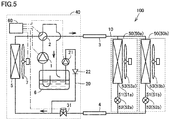
- Refrigeration cycle apparatus 100 is, for example, an air conditioner.
- Fig. 1 is a refrigerant circuit diagram of refrigeration cycle apparatus 100 according to the first embodiment of the present invention.
- refrigeration cycle apparatus 100 mainly includes an outdoor unit 40 and a plurality of indoor units 50. Outdoor unit 40 is placed outside, and the plurality of indoor units 50 are placed inside. Outdoor unit 40 and the plurality of indoor units 50 are connected by a gas-side connection pipe 3 and a liquid-side connection pipe 4.
- Outdoor unit 40 mainly includes a compressor 1, a four-way valve 2, an outdoor heat exchanger 5, an accumulator 6, an outdoor blower 7, an electric pump 21, a check valve 22, and a controller 60.
- Indoor unit 50 mainly includes an indoor heat exchanger 51, a decompressing apparatus 52 and an indoor blower 53.
- refrigeration cycle apparatus 100 includes two indoor units 50a and 50b.
- Indoor unit 50a includes an indoor heat exchanger 51a, a decompressing apparatus 52a and an indoor blower 53a.
- Indoor unit 50b includes an indoor heat exchanger 51b, a decompressing apparatus 52b and an indoor blower 53b.
- refrigeration cycle apparatus 100 includes two indoor units 50a and 50b in the present embodiment, refrigeration cycle apparatus 100 may include three or more indoor units 50.
- the number of indoor heat exchangers 51, the number of outdoor units 40, and the number of each element may be singular or plural.
- Compressor 1 is configured to compress and discharge suctioned refrigerant.
- Compressor 1 may be configured such that a volume thereof is variable.
- compressor 1 is configured such that the volume thereof changes by adjusting a rotation speed of compressor 1 based on an instruction from controller 60.
- Four-way valve 2 is configured to switch a flow of the refrigerant flowing through the refrigerant circuit between during a heating operation and during cooling and defrosting operations.
- four-way valve 2 is configured to switch between connecting the discharge side of compressor 1 to indoor heat exchangers 51b and 51b and connecting the discharge side of compressor 1 to outdoor heat exchanger 5 based on an instruction from controller 60.
- Outdoor heat exchanger 5 performs heat exchange between the refrigerant and outdoor air.
- Outdoor heat exchanger 5 is composed of, for example, a pipe and a fin. Outdoor heat exchanger 5 functions as an evaporator that evaporates the refrigerant during the heating operation, and functions as a condenser that condenses the refrigerant during the cooling operation and during the defrosting operation.
- Outdoor blower 7 is provided adjacent to outdoor heat exchanger 5. Outdoor blower 7 is configured to supply air flowing around outdoor heat exchanger 5. In the present embodiment, outdoor blower 7 is configured such that an amount of air flowing around outdoor heat exchanger 5 is adjusted and an amount of heat exchange between the air and the refrigerant is adjusted by adjusting a rotation speed of outdoor blower 7 based on an instruction from controller 60.
- Accumulator 6 is a container that can accumulate the refrigerant therein. Accumulator 6 is connected to the suction side of compressor 1. In accumulator 6, the refrigerant is subjected to gas-liquid separation. Accumulator 6 is arranged on the outlet side of an evaporator. That is, accumulator 6 is arranged on the low pressure side in the refrigerant circuit.
- Electric pump 21 is an electrically-driven pump. Electric pump 21 is configured to operate in accordance with a voltage applied to electric pump 21. In the present embodiment, electric pump 21 is configured such that an amount of discharge of electric pump 21 is adjusted by adjusting the voltage applied to electric pump 21 based on an instruction from controller 60.
- Check valve 22 is connected to electric pump 21 and liquid-side connection pipe 4.
- Check valve 22 is configured to flow the refrigerant from electric pump 21 to liquid-side connection pipe 4 and not to flow the refrigerant from liquid-side connection pipe 4 to electric pump 21.
- Controller 60 is configured to control the instruments, the apparatuses and the like of refrigeration cycle apparatus 100 by calculations, instructions and the like. Particularly, controller 60 is electrically connected to compressor 1, four-way valve 2, outdoor blower 7, electric pump 21, decompressing apparatuses 52a and 52b, and indoor blowers 53a and 53b, and is configured to control operations of these apparatuses.
- compressor 1, four-way valve 2, outdoor blower 7, electric pump 21, decompressing apparatuses 52a and 52b, and indoor blowers 53a and 53b and is configured to control operations of these apparatuses.
- electrical connection between controller 60 and the apparatuses in outdoor heat exchanger 5 is indicated by an alternate long and short dash line.
- electrical connection between controller 60 and the apparatuses in indoor heat exchanger 50 is not shown.
- Indoor heat exchangers 51a and 51b perform heat exchange between the refrigerant and indoor air.
- Each of indoor heat exchangers 51a and 51b is composed of, for example, a pipe and a fin.
- Each of indoor heat exchangers 51a and 51b functions as a condenser that condenses the refrigerant during the heating operation, and functions as an evaporator that evaporates the refrigerant during the cooling operation and during the defrosting operation.
- Decompressing apparatuses 52a and 52b are configured to expand and decompress the refrigerant condensed by a condenser.
- decompressing apparatuses 52a and 52b are electronic control valves.
- Indoor blowers 53a and 53b are provided adjacent to indoor heat exchangers 51a and 51b, respectively.
- indoor blowers 53a and 53b are configured such that an amount of air flowing around indoor heat exchangers 51a and 51b is adjusted and an amount of heat exchange between the air and the refrigerant is adjusted by adjusting rotation speeds of indoor blowers 53a and 53b based on an instruction from controller 60.
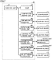
- Controller 60 mainly includes a control unit 61, a timer 62, a compressor driving unit 63, a four-way valve driving unit 64, an outdoor blower driving unit 65, an electric pump driving unit 66, a decompressing apparatus driving unit 67, and an indoor blower driving unit 68.
- Control unit 61 controls compressor driving unit 63, four-way valve driving unit 64, outdoor blower driving unit 65, electric pump driving unit 66, decompressing apparatus driving unit 67, indoor blower driving unit 68 and the like, based on signals from timer 62, a pressure measuring apparatus and a temperature measuring apparatus (both are not shown), and the like.
- Timer 62 measures a time period and transmits a signal based on the time period to control unit 61.
- the pressure measuring apparatus (not shown) is attached to the refrigerant circuit, and measures a pressure of the refrigerant and transmits a signal based on the pressure to control unit 61.
- the temperature measuring apparatus (not shown) is attached to the refrigerant circuit, and measures a temperature of the refrigerant and the air and transmits a signal based on the temperature to control unit 61.
- Compressor driving unit 63 drives compressor 1 based on an instruction from control unit 61. Specifically, compressor driving unit 63 controls a rotation speed of a motor (not shown) of compressor 1 by controlling a frequency of an alternating current flowing through the motor of compressor 1.
- Four-way valve driving unit 64 drives four-way valve 2 based on an instruction from control unit 61. Specifically, four-way valve driving unit 64 controls switching of four-way valve 2 by controlling a driving source such as a motor (not shown) attached to four-way valve 2.
- a driving source such as a motor (not shown) attached to four-way valve 2.
- Outdoor blower driving unit 65 drives outdoor blower 7 based on an instruction from control unit 61. Specifically, outdoor blower driving unit 65 controls the rotation speed of outdoor blower 7 by controlling a driving source such as a motor (not shown) attached to outdoor blower 7.
- a driving source such as a motor (not shown) attached to outdoor blower 7.
- Electric pump driving unit 66 drives electric pump 21 based on an instruction from control unit 61. Specifically, electric pump driving unit 66 controls the amount of discharge by controlling a voltage flowing through a motor (not shown) of electric pump 21.
- Decompressing apparatus driving unit 67 drives decompressing apparatuses 52a and 52b based on an instruction from control unit 61. Specifically, decompressing apparatus driving unit 67 controls a degree of opening of decompressing apparatuses 52a and 52b by controlling driving sources such as motors (not shown) attached to decompressing apparatuses 52a and 52b.
- Indoor blower driving unit 68 drives indoor blowers 53a and 53b based on an instruction from control unit 61. Specifically, indoor blower driving unit 68 controls the rotation speeds of indoor blowers 53a and 53b by controlling driving sources such as motors (not shown) attached to indoor blowers 53a and 53b.
- Refrigeration cycle apparatus 100 includes a first refrigerant route 10 and a second refrigerant route 20.
- first refrigerant route 10 the refrigerant flows in order of compressor 1, indoor heat exchanger (first heat exchanger) 51, liquid-side connection pipe (first pipe) 4, outdoor heat exchanger (second heat exchanger) 5, accumulator (low pressure receiver) 6, and compressor 1.
- first refrigerant route 10 includes compressor 1, four-way valve 2, gas-side connection pipe 3, indoor heat exchangers 51a and 51b, decompressing apparatuses 52a and 52b, liquid-side connection pipe 4, outdoor heat exchanger 5, and accumulator 6.
- the refrigerant flows through compressor 1, four-way valve 2, gas-side connection pipe 3, indoor heat exchangers 51a and 51b, decompressing apparatuses 52a and 52b, liquid-side connection pipe 4, outdoor heat exchanger 5, and four-way valve 2, and then, flows through accumulator 6 to compressor 1.
- refrigeration cycle apparatus 100 shown in Fig. 1 includes second refrigerant route 20 for discharging liquid refrigerant from inside accumulator 6.
- Second refrigerant route 20 is connected to liquid-side connection pipe 4 and accumulator 6.
- Liquid-side connection pipe 4 is connected to indoor heat exchanger 51 and outdoor heat exchanger 5 in first refrigerant route 10.
- Second refrigerant route 20 includes electric pump 21 and check valve 22.
- Second refrigerant route 20 extends from inside accumulator 6 through electric pump 21 and check valve 22 to liquid-side connection pipe 4 and is connected to liquid-side connection pipe 4.
- Electric pump 21 is configured to flow the refrigerant from accumulator 6 to liquid-side connection pipe 4.
- electric pump 21 is arranged outside accumulator 6.
- Electric pump 21 may be located inside or outside accumulator 6. That is, electric pump 21 may be arranged inside accumulator 6, or may be arranged outside accumulator 6.
- Check valve 22 may be arranged upstream of electric pump 21 in second refrigerant route 20, or may be arranged downstream of electric pump 21 in second refrigerant route 20.
- refrigeration cycle apparatus 100 does not necessarily need to include check valve 22.
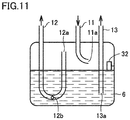
- Fig. 3 is a schematic view showing an internal structure of accumulator 6.
- Accumulator 6 generally has a cylindrical shape. As shown in Fig. 3 , accumulator 6 is a horizontal cylindrical accumulator in the present embodiment. Accumulator 6 may be a vertical cylindrical accumulator.
- First refrigerant route 10 includes an inflow pipe 11 and an outflow pipe 12.
- Second refrigerant route 20 includes a liquid draining pipe 13.
- Inflow pipe 11 and outflow pipe 12 of first refrigerant route 10 and liquid draining pipe 13 of second refrigerant route 20 are connected to accumulator 6.
- Inflow pipe 11, outflow pipe 12 and liquid draining pipe 13 are inserted into accumulator 6 from outside accumulator 6.
- Inflow pipe 11 is connected to four-way valve 2.
- Inflow pipe 11 includes a flow inlet 11a.
- Flow inlet 11a is located in accumulator 6.
- Flow inlet 11a is configured to flow the refrigerant into accumulator 6.
- the refrigerant flowing from four-way valve 2 to inflow pipe 11 flows into accumulator 6 through flow inlet 11a.
- Flow inlet 11a of inflow pipe 11 is oriented in a direction that is parallel to a liquid level of the refrigerant accumulated in accumulator 6. This reduces or prevents a phenomenon in which the refrigerant flowing into accumulator 6 through flow inlet 11a of inflow pipe 11 directly comes into collision with the liquid level of the refrigerant accumulated in accumulator 6, which causes disturbance of the liquid level of the refrigerant and generation of droplets of the liquid refrigerant. Therefore, the gas-liquid separation effect of accumulator 6 is not impaired.
- Outflow pipe 12 is connected to a suction port of compressor 1.
- Outflow pipe 12 includes a flow outlet 12a.
- Flow outlet (first refrigerant route flow outlet) 12a is located in accumulator 6.
- Flow outlet 12a is configured to allow the refrigerant to flow out of accumulator 6 to compressor 1.
- the refrigerant flowing from accumulator 6 to outflow pipe 12 is suctioned from the suction side of compressor 1.
- Outflow pipe 12 is formed in the U shape. Due to this shape, outflow pipe 12 is sometimes called "U-shaped pipe". Flow outlet 12a is provided at a tip of outflow pipe 12 located in accumulator 6. Flow outlet 12a of outflow pipe 12 is oriented upward in accumulator 6.
- Refrigeration cycle apparatus 100 is controlled based on an instruction from controller 60 such that the liquid level of the refrigerant accumulated in accumulator 6 becomes lower than flow outlet 12a of outflow pipe 12. Therefore, flow outlet 12a generally suctions only vapor refrigerant. Not only the refrigerant but also a part of a lubricating oil for lubricating the compressor flows out of compressor 1 and circulates through the refrigerant circuit together with the refrigerant. An amount of the lubricating oil circulating through the refrigerant circuit is small.
- the lubricating oil which is constantly a liquid, is subjected to gas-liquid separation in accumulator 6 and is accumulated in a lower part in accumulator 6. Excessive accumulation of the lubricating oil in accumulator 6 results in a shortage of the lubricating oil in compressor 1. Therefore, a bearing and the like of compressor 1 are damaged due to poor lubrication, and thus, compressor 1 fails.
- Outflow pipe 12 includes an oil return hole 12b.
- Oil return hole 12b is located in accumulator 6.
- Oil return hole 12b is configured to return the lubricating oil of compressor 1 from accumulator 6 to compressor 1.
- At least one oil return hole 12b is provided in outflow pipe 12. At least one of oil return holes 12b is provided near a lowermost part of outflow pipe 12 bent into a U shape. That is, oil return hole 12b is provided in a curved portion that connects straight portions of outflow pipe 12. Oil return hole 12b has a diameter of about several millimeters.
- oil return hole 12b When a dimension (size) of oil return hole 12b is increased, a larger amount of the lubricating oil can be returned to compressor 1. At the same time, however, a larger amount of the liquid refrigerant is also supplied to compressor 1. The liquid refrigerant dilutes the lubricating oil to thereby reduce a viscosity of the lubricating oil, which may cause poor lubrication of compressor 1. As described above, the dimension of oil return hole 12b, whether it is too large or too small, leads to a failure of compressor 1. Therefore, it is necessary to design oil return hole 12b to have an appropriate dimension.
- Liquid draining pipe 13 is connected to electric pump 21.
- Liquid draining pipe 13 includes a flow outlet 13a.
- Flow outlet (second refrigerant route flow outlet) 13a is located in accumulator 6.
- Flow outlet 13a is configured to allow the refrigerant to flow out of accumulator 6 to liquid-side connection pipe 4.
- Flow outlet 13a is arranged above oil return hole 12b.
- Flow outlet 13a of liquid draining pipe 13 is oriented downward in accumulator 6.
- Liquid draining pipe 13 is desirably inserted to reach a region near a lower end in accumulator 6 in order to discharge the liquid refrigerant accumulated in a bottom part of accumulator 6.
- flow outlet 13a provided at a lower end of liquid draining pipe 13 is provided at a position higher than at least one oil return hole 12b, oil return to compressor 1 through oil return hole 12b is impossible. Therefore, flow outlet 13a of liquid draining pipe 13 is arranged above oil return hole 12b arranged in the lowermost part.
- second refrigerant route 20 includes check valve 22 in order to prevent backflow of the refrigerant in second refrigerant route 20.
- the high-temperature and high-pressure vapor refrigerant compressed in compressor 1 flows through four-way valve 2 to outdoor heat exchanger 5, where the high-temperature and high-pressure vapor refrigerant dissipates heat to the outdoor air and condenses into high-pressure liquid refrigerant.
- the high-pressure liquid refrigerant flows through liquid-side connection pipe 4 to decompressing apparatuses 52a and 52b, where the high-pressure liquid refrigerant expands and is decompressed into low-temperature and low-pressure gas-liquid two-phase refrigerant.
- the low-temperature and low-pressure gas-liquid two-phase refrigerant flows to indoor heat exchangers 51a and 51b, where the low-temperature and low-pressure gas-liquid two-phase refrigerant absorbs heat from the indoor air and evaporates into low-pressure vapor refrigerant.
- the low-pressure vapor refrigerant flows through gas-side connection pipe 3, four-way valve 2 and accumulator 6 back to compressor 1, where the low-pressure vapor refrigerant is compressed.
- the refrigerant circulates through the refrigerant circuit as described above.
- the high-temperature and high-pressure vapor refrigerant compressed in compressor 1 flows through four-way valve 2 and gas-side connection pipe 3 to indoor heat exchangers 51a and 51b, where the high-temperature and high-pressure vapor refrigerant dissipates heat to the indoor air and condenses into high-pressure liquid refrigerant.
- the high-pressure liquid refrigerant flows to decompressing apparatuses 52a and 52b, where the high-pressure liquid refrigerant expands and is decompressed into low-temperature and low-pressure gas-liquid two-phase refrigerant.
- the low-temperature and low-pressure gas-liquid two-phase refrigerant flows through liquid-side connection pipe 4 to outdoor heat exchanger 5, where the low-temperature and low-pressure gas-liquid two-phase refrigerant absorbs heat from the outdoor air and evaporates into low-pressure vapor refrigerant.
- the low-pressure vapor refrigerant flows through four-way valve 2 and accumulator 6 back to compressor 1, where the low-pressure vapor refrigerant is compressed.
- the refrigerant circulates through the refrigerant circuit as described above.
- controller 60 determines that an amount of frost formed on outdoor heat exchanger 5 is large. Based on this determination by controller 60, the defrosting operation is performed in refrigeration cycle apparatus 100.
- Switching from the heating operation to the defrosting operation is performed by switching four-way valve 2 from a position for the heating operation ( Fig. 1 ) to a position for the cooling operation ( Fig. 4 ).
- a flow direction of the refrigerant, a gas-liquid phase change and a heat transfer manner during the defrosting operation are the same as those during the cooling operation.
- the low-temperature and low-pressure gas-liquid two-phase refrigerant flows through indoor heat exchangers 51a and 51b.
- indoor blowers 53a and 53b are desirably stopped in order to prevent cold air from blowing into an indoor space.
- controller 60 determines that defrosting of outdoor heat exchanger 5 has been completed. Based on this determination by controller 60, four-way valve 2 is switched to the heating position and the heating operation is restarted in refrigeration cycle apparatus 100.
- outdoor heat exchanger 5 functions as a condenser during the defrosting operation, a large amount of the condensed liquid refrigerant is present in outdoor heat exchanger 5.
- four-way valve 2 is switched to the heating position at the start of the heating operation, the flow direction of the refrigerant in outdoor heat exchanger 5 is reversed and the liquid refrigerant in outdoor heat exchanger 5 flows through four-way valve 2 into accumulator 6 and accumulates in the lower part of accumulator 6.
- the liquid refrigerant flowing from second refrigerant route 20 joins, in liquid-side connection pipe 4, with the low-pressure gas-liquid two-phase refrigerant flowing through decompressing apparatuses 52a and 52b, and flows into outdoor heat exchanger 5.
- the gas-liquid two-phase refrigerant absorbs heat from the outdoor air and evaporates into low-pressure vapor refrigerant in outdoor heat exchanger 5, and the low-pressure vapor refrigerant flows through the refrigerant circuit. Therefore, provision of the heating capacity can be made earlier.
- electric pump 21 is driven when the heating operation during which the refrigerant flows from compressor 1 to indoor heat exchanger 51 starts after the defrosting operation during which the refrigerant flows from compressor 1 to outdoor heat exchanger 5 ends. Discharge of the liquid refrigerant in accumulator 6 by electric pump 21 can make earlier provision of the heating capacity at the time of return to the heating operation from the end of the defrosting operation.
- provision of the heating capacity can also be made earlier at startup of the heating operation of refrigeration cycle apparatus 100 that is in a non-operation state during wintertime.
- electric pump 21 is driven at startup of compressor 1, and is stopped after the refrigerant is flown from accumulator 6 to liquid-side connection pipe 4 by electric pump 21.
- the refrigerant in the refrigerant circuit liquefies and condenses and accumulates in a low-temperature portion. Therefore, particularly when refrigeration cycle apparatus 100 is in a non-operation state for a long time during wintertime, the liquid refrigerant accumulates in outdoor heat exchanger 5 exposed to the outdoor air.
- the liquid refrigerant flows into and accumulates in accumulator 6 at the start of the heating operation. Therefore, electric pump 21 is preferably operated at the start of the heating operation after refrigeration cycle apparatus 100 is in a non-operation state for a long time.
- electric pump 21 included in second refrigerant route 20 is configured to flow the refrigerant from accumulator 6 to liquid-side connection pipe 4. Therefore, since electric pump 21 flows the refrigerant from accumulator 6 to liquid-side connection pipe 4, the liquid refrigerant accumulated in accumulator 6 can be rapidly discharged.
- Electric pump 21 is configured such that the amount of discharge of the liquid refrigerant can be freely adjusted simply by applying the voltage to electric pump 21, and thus, the liquid refrigerant can be rapidly discharged immediately after startup of refrigeration cycle apparatus 100. Therefore, a rapid start after startup of refrigeration cycle apparatus 100 can be implemented. Thus, a sufficient amount of liquid discharge is obtained immediately after startup of refrigeration cycle apparatus 100.
- electric pump 21 is configured such that the amount of discharge of the liquid refrigerant can be freely adjusted by adjusting the voltage applied to electric pump 21. Therefore, the liquid refrigerant in accumulator 6 can be actively discharged.
- flow outlet 13a of liquid draining pipe 13 is arranged above oil return hole 12b. Therefore, oil return to compressor 1 through oil return hole 12b is possible.
- electric pump 21 is driven at startup of compressor 1, and is stopped after the refrigerant is flown from accumulator 6 to liquid-side connection pipe 4 by electric pump 21. Since the refrigerant is likely to accumulate in accumulator 6 when compressor 1 is in a non-operation state, electric pump 21 is used to discharge the liquid refrigerant at startup of compressor 1, and thus, provision of the heating capacity in an early stage can be implemented. In addition, since electric pump 21 is stopped after the liquid refrigerant is discharged from accumulator 6 after startup of compressor 1, an increase in motive power of electric pump 21 can be suppressed.
- electric pump 21 is driven when the heating operation starts after the defrosting operation ends. Therefore, provision of the heating capacity in an early stage can be implemented at the start of the heating operation after the end of the defrosting operation.
- refrigeration cycle apparatus 100 is different from refrigeration cycle apparatus 100 according to the first embodiment of the present invention in that an on-off valve 31 is provided in first refrigerant route 10.
- on-off valve 31 is filled with a black color in order to show a state in which on-off valve 31 is closed.
- first refrigerant route 10 includes on-off valve 31.
- On-off valve 31 is configured to open and close first refrigerant route 10 between indoor heat exchanger 51 and outdoor heat exchanger 5 in first refrigerant route 10.
- On-off valve 31 is, for example, a solenoid valve.
- Second refrigerant route 20 is connected to liquid-side connection pipe 4 between on-off valve 31 and outdoor heat exchanger 5.
- controller 60 includes an on-off valve driving unit 69.
- On-off valve driving unit 69 drives on-off valve 31 based on an instruction from control unit 61.
- on-off valve driving unit 69 controls opening and closing of on-off valve 31 by controlling a driving source such as a motor (not shown) attached to on-off valve 31.
- the liquid refrigerant condensed in indoor heat exchangers 51a and 51b does not return to compressor 1.
- the liquid refrigerant discharged from accumulator 6 by electric pump 21 is subjected to heat exchange with the outdoor air and evaporates in outdoor heat exchanger 5, and is supplied to indoor unit 50 through compressor 1. Therefore, the refrigerant in accumulator 6 is discharged immediately.
- electric pump 21 is driven in a state where on-off valve 31 closes first refrigerant route 10 at startup of compressor 1, and after the refrigerant is flown from accumulator 6 to liquid-side connection pipe 4 by electric pump 21, on-off valve 31 opens first refrigerant route 10. Therefore, ensuring of the reliability and provision of the heating capacity in an early stage can be both achieved.
- Refrigeration cycle apparatus 100 according to a third embodiment of the present invention will be described with reference to Fig. 8 .
- Refrigeration cycle apparatus 100 according to the present embodiment is configured similarly to above-described refrigeration cycle apparatus 100 according to the first embodiment.
- on-off valve 31 is provided in first refrigerant route 10.
- decompressing apparatuses 52a and 52b are filled in a black color in order to show a state in which decompressing apparatuses 52a and 52b are closed.
- first refrigerant route 10 includes decompressing apparatuses 52a and 52b.
- Decompressing apparatuses 52a and 52b are configured to open and close first refrigerant route 10 between indoor heat exchanger 51 and outdoor heat exchanger 5 in first refrigerant route 10.
- electric pump 21 is driven in a state where decompressing apparatuses 52a and 52b close first refrigerant route 10 at startup of compressor 1. After the refrigerant is flown from accumulator 6 to liquid-side connection pipe 4 by electric pump 21, decompressing apparatuses 52a and 52b open first refrigerant route 10.
- electric pump 21 is driven in a state where decompressing apparatuses 52a and 52b close first refrigerant route 10 at startup of compressor 1, and after the refrigerant is flown from accumulator 6 to liquid-side connection pipe 4 by electric pump 21, decompressing apparatuses 52a and 52b open first refrigerant route 10. Therefore, ensuring of the reliability and provision of the heating capacity in an early stage can be both achieved.
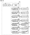
- refrigeration cycle apparatus 100 according to a fourth embodiment of the present invention is different from refrigeration cycle apparatus 100 according to the first embodiment of the present invention in that refrigeration cycle apparatus 100 according to the fourth embodiment of the present invention includes a liquid level sensor 32.
- Refrigeration cycle apparatus 100 in the present embodiment includes liquid level sensor 32.
- Liquid level sensor 32 is configured to detect the liquid level of the refrigerant in accumulator 6.
- Liquid level sensor 32 is provided in accumulator 6.
- Liquid level sensor 32 is electrically connected to controller 60.
- Liquid level sensor 32 is, for example, a liquid level detector.
- a type of the liquid level detector may be, for example, a capacitance type, a heater type or a float type.
- the capacitance type a difference in dielectric constant between a liquid and a vapor between electrodes is detected.
- the heater type a difference in amount of heat dissipation between a liquid and a vapor is detected.
- the float type a position of a float is detected.
- controller 60 includes a liquid level measurement unit 70.
- Liquid level measurement unit 70 measures a height of the liquid level of the refrigerant based on a signal from liquid level sensor 32, and transmits a signal based on the liquid level to control unit 61.
- liquid level sensor 32 is arranged below flow outlet 12a of outflow pipe 12. That is, liquid level sensor 32 is located vertically below flow outlet 12a. Electric pump 21 is driven when liquid level sensor 32 detects the liquid level of the refrigerant below flow outlet 12a. Electric pump 21 is driven while liquid level sensor 32 is detecting the liquid level of the refrigerant. Electric pump 21 is stopped when liquid level sensor 32 no longer detects the liquid level of the refrigerant.
- liquid level sensor 32 is provided vertically below flow outlet 12a, liquid level sensor 32 can detect a rise in liquid level before the liquid level of the refrigerant rises and arrives at flow outlet 12a. Since electric pump 21 is driven while liquid level sensor 32 is detecting the liquid level of the refrigerant, a rise in liquid level of the refrigerant and arrival of the liquid level of the refrigerant at flow outlet 12a can be suppressed.
- liquid level sensor 32 detects the liquid level of the refrigerant.
- Controller 60 drives electric pump 21 based on a signal about detection of the liquid level of the refrigerant from liquid level sensor 32.
- electric pump 21 When electric pump 21 is operated, the refrigerant in accumulator 6 is discharged. Electric pump 21 is driven until liquid level sensor 32 no longer detects the liquid level of the refrigerant. This can reduce or prevent a phenomenon in which the liquid level in accumulator 6 goes beyond flow outlet 12a of outflow pipe 12 and compressor 1 suctions the liquid refrigerant. Therefore, a failure of compressor 1 caused by suction of the liquid refrigerant into compressor 1 can be suppressed. Furthermore, electric pump 21 is stopped when liquid level sensor 32 no longer detects the liquid level of the refrigerant.
- electric pump 21 is driven when liquid level sensor 32 detects the liquid level of the refrigerant below flow outlet 12a. Therefore, since electric pump 21 is driven when liquid level sensor 32 directly detects a rise in liquid level of the refrigerant in accumulator 6, the reliability of discharge of the liquid refrigerant is enhanced.
- electric pump 21 is driven while liquid level sensor 32 is detecting the liquid level of the refrigerant, and electric pump 21 is stopped when liquid level sensor 32 no longer detects the liquid level of the refrigerant. Therefore, arrival of the liquid level of the refrigerant at flow outlet 12a can be suppressed. In addition, since electric pump 21 is stopped after the refrigerant in accumulator 6 is discharged, an increase in motive power of electric pump 21 can be suppressed.
- refrigeration cycle apparatus 100 includes a refrigerant circuit similar to that of above-described refrigeration cycle apparatus 100 according to the first embodiment.
- a flow of the refrigerant during the heating operation is indicated by a solid arrow
- a flow of the refrigerant during the cooling operation is indicated by a dashed arrow.
- electric pump 21 may be constantly operated during operation of compressor 1, regardless of the time that elapses from the start of operation.
- electric pump 21 is constantly driven while compressor 1 is being driven. A certain amount of the liquid refrigerant constantly flows out of accumulator 6 through liquid draining pipe 13, and thus, the operation of refrigeration cycle apparatus 100 is stabilized in a state where a corresponding amount of the liquid refrigerant is introduced from inflow pipe 11.
- the heat transfer performance of an evaporator is better when the refrigerant flowing through the evaporator is in a gas-liquid two-phase state than when the refrigerant flowing through the evaporator is in a vapor single-phase state.
- the refrigerant at an outlet of the evaporator is controlled to be in a vapor single-phase state, in order to prevent an overflow of the liquid refrigerant in accumulator 6 and suction of the liquid refrigerant into compressor 1.
- the state of the refrigerant in the evaporator can be controlled to a gas-liquid two-phase state in the entire evaporator. As a result, the performance of the evaporator is enhanced, and thus, the highly-efficient operation becomes possible.
- refrigeration cycle apparatus 100 in the present embodiment, electric pump 21 is constantly driven while compressor 1 is being driven, and thus, the operation of refrigeration cycle apparatus 100 is stabilized. In addition, the performance of the evaporator is enhanced, and thus, the highly-efficient operation becomes possible.
Landscapes
- Engineering & Computer Science (AREA)
- Physics & Mathematics (AREA)
- Mechanical Engineering (AREA)
- Thermal Sciences (AREA)
- General Engineering & Computer Science (AREA)
- Chemical & Material Sciences (AREA)
- Analytical Chemistry (AREA)
- Power Engineering (AREA)
- Compression-Type Refrigeration Machines With Reversible Cycles (AREA)
Applications Claiming Priority (1)
| Application Number | Priority Date | Filing Date | Title |
|---|---|---|---|
| PCT/JP2018/032899 WO2020049660A1 (fr) | 2018-09-05 | 2018-09-05 | Dispositif à cycle frigorifique |
Publications (2)
| Publication Number | Publication Date |
|---|---|
| EP3848652A1 true EP3848652A1 (fr) | 2021-07-14 |
| EP3848652A4 EP3848652A4 (fr) | 2021-09-08 |
Family
ID=69721904
Family Applications (1)
| Application Number | Title | Priority Date | Filing Date |
|---|---|---|---|
| EP18932804.0A Withdrawn EP3848652A4 (fr) | 2018-09-05 | 2018-09-05 | Dispositif à cycle frigorifique |
Country Status (4)
| Country | Link |
|---|---|
| US (1) | US11802722B2 (fr) |
| EP (1) | EP3848652A4 (fr) |
| JP (1) | JP6991346B2 (fr) |
| WO (1) | WO2020049660A1 (fr) |
Families Citing this family (1)
| Publication number | Priority date | Publication date | Assignee | Title |
|---|---|---|---|---|
| US11346583B2 (en) * | 2018-06-27 | 2022-05-31 | Emerson Climate Technologies, Inc. | Climate-control system having vapor-injection compressors |
Family Cites Families (10)
| Publication number | Priority date | Publication date | Assignee | Title |
|---|---|---|---|---|
| JPS63104959U (fr) | 1986-12-24 | 1988-07-07 | ||
| JPH0712414A (ja) * | 1993-06-25 | 1995-01-17 | Sanyo Electric Co Ltd | 空気調和機 |
| JPH1194374A (ja) | 1997-09-26 | 1999-04-09 | Mitsubishi Heavy Ind Ltd | 空気調和機及び空気調和機の室外機 |
| JP4756622B2 (ja) * | 2001-09-14 | 2011-08-24 | 株式会社前川製作所 | 満液式蒸発器を用いた冷凍サイクル装置 |
| JP2004309029A (ja) * | 2003-04-08 | 2004-11-04 | Matsushita Electric Ind Co Ltd | 冷凍サイクル装置 |
| US6964178B2 (en) * | 2004-02-27 | 2005-11-15 | Denso Corporation | Air conditioning system for vehicle |
| JP5334905B2 (ja) * | 2010-03-31 | 2013-11-06 | 三菱電機株式会社 | 冷凍サイクル装置 |
| JP5328713B2 (ja) * | 2010-04-27 | 2013-10-30 | 三菱電機株式会社 | 冷凍サイクル装置 |
| JP2012162125A (ja) | 2011-02-04 | 2012-08-30 | Calsonic Kansei Corp | 冷凍サイクル装置 |
| WO2013125006A1 (fr) | 2012-02-23 | 2013-08-29 | トヨタ自動車株式会社 | Dispositif de refroidissement et véhicule monté avec ce dernier et procédé permettant de commander un dispositif de refroidissement |
-
2018
- 2018-09-05 WO PCT/JP2018/032899 patent/WO2020049660A1/fr not_active Ceased
- 2018-09-05 EP EP18932804.0A patent/EP3848652A4/fr not_active Withdrawn
- 2018-09-05 US US17/256,746 patent/US11802722B2/en active Active
- 2018-09-05 JP JP2020540924A patent/JP6991346B2/ja not_active Expired - Fee Related
Also Published As
| Publication number | Publication date |
|---|---|
| EP3848652A4 (fr) | 2021-09-08 |
| WO2020049660A1 (fr) | 2020-03-12 |
| US11802722B2 (en) | 2023-10-31 |
| US20210364201A1 (en) | 2021-11-25 |
| JP6991346B2 (ja) | 2022-01-12 |
| JPWO2020049660A1 (ja) | 2021-08-12 |
Similar Documents
| Publication | Publication Date | Title |
|---|---|---|
| CN100387907C (zh) | 空调装置 | |
| US8353180B2 (en) | Refrigerating apparatus | |
| US6986259B2 (en) | Refrigerator | |
| EP3287724A1 (fr) | Réfrigérateur | |
| US20020129612A1 (en) | Refrigeration cycle | |
| JP2008267787A5 (fr) | ||
| CN103604241B (zh) | 空调器及其控制方法 | |
| EP3693680A1 (fr) | Appareil de cycle de réfrigération | |
| JP2002242833A (ja) | 冷凍サイクル装置 | |
| KR20130041712A (ko) | 냉동 사이클 장치 | |
| US7475557B2 (en) | Refrigerator | |
| JP2012083010A (ja) | 冷凍サイクル装置 | |
| JP2002257427A (ja) | 冷凍空調装置、及びその運転方法 | |
| US11802722B2 (en) | Refrigeration cycle apparatus | |
| JP2015048988A (ja) | アキュムレータ及び冷凍装置 | |
| JP4269476B2 (ja) | 冷凍装置 | |
| WO2019106755A1 (fr) | Climatiseur | |
| JP4023387B2 (ja) | 冷凍装置 | |
| JP6685472B2 (ja) | 冷凍装置 | |
| CN117751265A (zh) | 冰箱 | |
| CN110398099B (zh) | 热泵系统及其控制方法和空调器 | |
| JPWO2020021595A1 (ja) | ショーケースおよびクーリングユニット | |
| JP2018173195A (ja) | 冷凍装置 | |
| JP6812885B2 (ja) | 冷凍装置及び熱源装置 | |
| CN116294257B (zh) | 一种制冷系统及其防回液控制方法 |
Legal Events
| Date | Code | Title | Description |
|---|---|---|---|
| STAA | Information on the status of an ep patent application or granted ep patent |
Free format text: STATUS: THE INTERNATIONAL PUBLICATION HAS BEEN MADE |
|
| PUAI | Public reference made under article 153(3) epc to a published international application that has entered the european phase |
Free format text: ORIGINAL CODE: 0009012 |
|
| STAA | Information on the status of an ep patent application or granted ep patent |
Free format text: STATUS: REQUEST FOR EXAMINATION WAS MADE |
|
| 17P | Request for examination filed |
Effective date: 20210225 |
|
| AK | Designated contracting states |
Kind code of ref document: A1 Designated state(s): AL AT BE BG CH CY CZ DE DK EE ES FI FR GB GR HR HU IE IS IT LI LT LU LV MC MK MT NL NO PL PT RO RS SE SI SK SM TR |
|
| A4 | Supplementary search report drawn up and despatched |
Effective date: 20210806 |
|
| RIC1 | Information provided on ipc code assigned before grant |
Ipc: F25B 49/02 20060101ALI20210802BHEP Ipc: F25B 1/00 20060101ALI20210802BHEP Ipc: F25B 43/00 20060101AFI20210802BHEP |
|
| DAV | Request for validation of the european patent (deleted) | ||
| DAX | Request for extension of the european patent (deleted) | ||
| GRAP | Despatch of communication of intention to grant a patent |
Free format text: ORIGINAL CODE: EPIDOSNIGR1 |
|
| STAA | Information on the status of an ep patent application or granted ep patent |
Free format text: STATUS: GRANT OF PATENT IS INTENDED |
|
| STAA | Information on the status of an ep patent application or granted ep patent |
Free format text: STATUS: THE APPLICATION HAS BEEN WITHDRAWN |
|
| INTG | Intention to grant announced |
Effective date: 20240903 |
|
| 18W | Application withdrawn |
Effective date: 20240830 |