EP3848660B1 - Dichter anschluss eines verbindungsstücks an einen koaxialen röhrenwärmetauscher - Google Patents
Dichter anschluss eines verbindungsstücks an einen koaxialen röhrenwärmetauscher Download PDFInfo
- Publication number
- EP3848660B1 EP3848660B1 EP20217470.2A EP20217470A EP3848660B1 EP 3848660 B1 EP3848660 B1 EP 3848660B1 EP 20217470 A EP20217470 A EP 20217470A EP 3848660 B1 EP3848660 B1 EP 3848660B1
- Authority
- EP
- European Patent Office
- Prior art keywords
- tubes
- tube
- connector
- external
- internal
- Prior art date
- Legal status (The legal status is an assumption and is not a legal conclusion. Google has not performed a legal analysis and makes no representation as to the accuracy of the status listed.)
- Active
Links
Images


Classifications
-
- F—MECHANICAL ENGINEERING; LIGHTING; HEATING; WEAPONS; BLASTING
- F28—HEAT EXCHANGE IN GENERAL
- F28F—DETAILS OF HEAT-EXCHANGE AND HEAT-TRANSFER APPARATUS, OF GENERAL APPLICATION
- F28F9/00—Casings; Header boxes; Auxiliary supports for elements; Auxiliary members within casings
- F28F9/02—Header boxes; End plates
- F28F9/04—Arrangements for sealing elements into header boxes or end plates
- F28F9/16—Arrangements for sealing elements into header boxes or end plates by permanent joints, e.g. by rolling
- F28F9/18—Arrangements for sealing elements into header boxes or end plates by permanent joints, e.g. by rolling by welding
-
- F—MECHANICAL ENGINEERING; LIGHTING; HEATING; WEAPONS; BLASTING
- F28—HEAT EXCHANGE IN GENERAL
- F28D—HEAT-EXCHANGE APPARATUS, NOT PROVIDED FOR IN ANOTHER SUBCLASS, IN WHICH THE HEAT-EXCHANGE MEDIA DO NOT COME INTO DIRECT CONTACT
- F28D7/00—Heat-exchange apparatus having stationary tubular conduit assemblies for both heat-exchange media, the media being in contact with different sides of a conduit wall
- F28D7/10—Heat-exchange apparatus having stationary tubular conduit assemblies for both heat-exchange media, the media being in contact with different sides of a conduit wall the conduits being arranged one within the other, e.g. concentrically
- F28D7/106—Heat-exchange apparatus having stationary tubular conduit assemblies for both heat-exchange media, the media being in contact with different sides of a conduit wall the conduits being arranged one within the other, e.g. concentrically consisting of two coaxial conduits or modules of two coaxial conduits
-
- F—MECHANICAL ENGINEERING; LIGHTING; HEATING; WEAPONS; BLASTING
- F28—HEAT EXCHANGE IN GENERAL
- F28F—DETAILS OF HEAT-EXCHANGE AND HEAT-TRANSFER APPARATUS, OF GENERAL APPLICATION
- F28F11/00—Arrangements for sealing leaky tubes and conduits
-
- F—MECHANICAL ENGINEERING; LIGHTING; HEATING; WEAPONS; BLASTING
- F28—HEAT EXCHANGE IN GENERAL
- F28F—DETAILS OF HEAT-EXCHANGE AND HEAT-TRANSFER APPARATUS, OF GENERAL APPLICATION
- F28F9/00—Casings; Header boxes; Auxiliary supports for elements; Auxiliary members within casings
- F28F9/02—Header boxes; End plates
- F28F9/0246—Arrangements for connecting header boxes with flow lines
- F28F9/0248—Arrangements for sealing connectors to header boxes
-
- F—MECHANICAL ENGINEERING; LIGHTING; HEATING; WEAPONS; BLASTING
- F28—HEAT EXCHANGE IN GENERAL
- F28F—DETAILS OF HEAT-EXCHANGE AND HEAT-TRANSFER APPARATUS, OF GENERAL APPLICATION
- F28F9/00—Casings; Header boxes; Auxiliary supports for elements; Auxiliary members within casings
- F28F9/02—Header boxes; End plates
- F28F9/0246—Arrangements for connecting header boxes with flow lines
- F28F9/0251—Massive connectors, e.g. blocks; Plate-like connectors
- F28F9/0253—Massive connectors, e.g. blocks; Plate-like connectors with multiple channels, e.g. with combined inflow and outflow channels
-
- F—MECHANICAL ENGINEERING; LIGHTING; HEATING; WEAPONS; BLASTING
- F28—HEAT EXCHANGE IN GENERAL
- F28F—DETAILS OF HEAT-EXCHANGE AND HEAT-TRANSFER APPARATUS, OF GENERAL APPLICATION
- F28F9/00—Casings; Header boxes; Auxiliary supports for elements; Auxiliary members within casings
- F28F9/02—Header boxes; End plates
- F28F9/0246—Arrangements for connecting header boxes with flow lines
- F28F9/0256—Arrangements for coupling connectors with flow lines
-
- F—MECHANICAL ENGINEERING; LIGHTING; HEATING; WEAPONS; BLASTING
- F28—HEAT EXCHANGE IN GENERAL
- F28F—DETAILS OF HEAT-EXCHANGE AND HEAT-TRANSFER APPARATUS, OF GENERAL APPLICATION
- F28F9/00—Casings; Header boxes; Auxiliary supports for elements; Auxiliary members within casings
- F28F9/26—Arrangements for connecting different sections of heat-exchange elements, e.g. of radiators
-
- F—MECHANICAL ENGINEERING; LIGHTING; HEATING; WEAPONS; BLASTING
- F28—HEAT EXCHANGE IN GENERAL
- F28F—DETAILS OF HEAT-EXCHANGE AND HEAT-TRANSFER APPARATUS, OF GENERAL APPLICATION
- F28F2275/00—Fastening; Joining
- F28F2275/02—Fastening; Joining by using bonding materials; by embedding elements in particular materials
- F28F2275/025—Fastening; Joining by using bonding materials; by embedding elements in particular materials by using adhesives
-
- F—MECHANICAL ENGINEERING; LIGHTING; HEATING; WEAPONS; BLASTING
- F28—HEAT EXCHANGE IN GENERAL
- F28F—DETAILS OF HEAT-EXCHANGE AND HEAT-TRANSFER APPARATUS, OF GENERAL APPLICATION
- F28F2275/00—Fastening; Joining
- F28F2275/04—Fastening; Joining by brazing
-
- F—MECHANICAL ENGINEERING; LIGHTING; HEATING; WEAPONS; BLASTING
- F28—HEAT EXCHANGE IN GENERAL
- F28F—DETAILS OF HEAT-EXCHANGE AND HEAT-TRANSFER APPARATUS, OF GENERAL APPLICATION
- F28F2275/00—Fastening; Joining
- F28F2275/06—Fastening; Joining by welding
Definitions
- the present invention relates in particular to a method for the sealed connection of a connector to a coaxial tubular heat exchanger, as well as a fluid connection device, in particular for a vehicle air conditioning circuit.
- the technical background includes, in particular, documents WO-A1-2011/057594 , WO-A1-2019/05058 , EP-A1-0 276 521 , EP-A1-2 199 721 , GB-A-2 0285 574 , US-A1-2009/260586 And WO-A1-2007/013439 .
- a heat exchanger is metallic and is connected to the corresponding pipes of the air conditioning circuit which in particular include flexible hoses, via connectors mounted at each end of the exchanger, which may for example be of the plate type, consisting of a stack of flat tubes and carrying out the heat exchange both by convection with the air outside the exchanger and by conduction, or of the multi-tube type which in its simplest version is of the coaxial counter-current tubular type, then carrying out the heat exchange without the aforementioned convection.
- this coaxial exchanger generally defines at least one radially internal channel delimited by a sleeve and intended to convey the fluid from the high pressure portion of the circuit, and at least one radially external channel between the sleeve and the casing of the exchanger. and intended to convey the fluid from the low pressure portion of the circuit.
- the sleeve and the casing are formed from a single piece and connected together by longitudinal fins distributed around the circumference of the exchanger.
- a major drawback of these internal coaxial exchangers equipped with female connectors lies in the mutual proximity of the generated welding or brazing lines which, in particular for successive brazing operations, generate risks of reflow of the previous brazing, and also in the need to carry out these welds or brazing blindly with risks of non-sealing at the junction and/or penetration of the brazing into the corresponding internal or external channel which can therefore lead to pressure losses, pollution or even blockage of these channels.
- a major drawback of the coaxial internal exchangers presented in these last two documents is that their assembly to a connector requires at least two brazing operations to be carried out at the same time and at least one of which, relating to the junction to be made between the connector and the internal sleeve, is necessarily "blind" or in difficult conditions due to its location inside the connector. This results in significant risks of non-conformity of the connection and therefore leakage of the transferred fluid.
- these brazing operations involve a relatively high manufacturing cost and a relatively high scrap rate for the connection obtained.
- the Applicant proposed a solution in the document EP-A1-2 199 721
- This solution consists of assembling the connector to the casing by welding, and to the sleeve by at least one annular sealing gasket which is mounted on an axial extension of the sleeve relative to the casing.
- the axial distance between the gasket and the weld line is sufficiently large so that this gasket is not altered by welding.
- the exchanger being formed from a single piece, the sleeve and the casing are inseparable and are therefore mounted simultaneously in the connector.
- An aim of the present invention is to propose an alternative to this solution.
- the internal and external tubes of the exchanger are independent. They are thus mounted one after the other in or on the connector.
- the external tube is mounted in step a) and secured to the connector in step b).
- This securing can be achieved by welding or brazing if the external tube and the connector are metallic.
- their securing could be ensured by gluing, by electron beam welding, etc.
- the internal tube is not yet inserted into the external tube and therefore does not risk being altered by the securing operation, and for example by the heating induced by securing by welding.
- the internal tube is then inserted in step c) into the external tube, until the internal tube cooperates in a sealed manner with the connector.
- the inner tube is connected indirectly to the connector, via the outer tube. This connection of the tubes is carried out in step d) and prevents any relative movement between the tubes during operation.
- the joining of the internal and external tubes is achieved by crimping the external tube onto the internal tube, by simultaneously bending the internal and external tubes, or by welding the ends of the internal and external tubes opposite the connector.
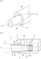
- THE figures 1 to 6 illustrate an embodiment of a fluid connection device 10 according to the invention, for an air conditioning circuit of a vehicle, in particular an automobile.
- the exchanger 14 has a generally elongated shape and comprises two coaxial tubes extending one inside the other.
- the inner tube is referenced 14a and the outer tube is referenced 14b.
- the outer tube 14b defines around the inner tube 14a an annular channel C1 for circulation of a first fluid, and the inner tube 14a defines a second internal channel C2 for circulation of a second fluid ( Figure 3 ).
- one of the tubes generally has projections, such as fins, resting on the other of the tubes to keep them at a distance from each other.
- the fins may extend parallel to the longitudinal axis X of the exchanger 14 or in a helical manner around this axis. They may be continuous or discontinuous.
- the external tube 14b can comprise on its internal cylindrical surface surrounding the internal tube 14a internal fins 15 which bear on an external cylindrical surface of the internal tube 14a ( Figure 3 ).
- the inner tube 14a may comprise on its external cylindrical surface surrounded by the outer tube 14b external fins which bear on an internal cylindrical surface of the outer tube 14b.
- the tubes 14a, 14b may be made of the same or different materials. They may be made of metal alloy(s) or plastic material(s) for example.
- the connector 12 is located at a longitudinal end of the exchanger 14, the opposite longitudinal end of which is connected to another type of connector 16, which is not part of the invention.
- interchange 14 has a straight shape.
- the exchanger 14 has a shape presenting several bends.
- the exchanger 14 of there Figure 2 has undergone a forming or shaping or bending step, from the initial shape of the Figure 1 .
- this shaping can make it possible to secure the tubes 14a, 14b together, in particular in the areas where the tubes are bent simultaneously and plastically deformed by being clamped against each other.
- the device 10 of the Figure 2 is ready to be installed in an air conditioning circuit and used.
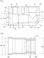
- Figure 4 is a larger scale view of the connector 12 and its connection to one end of the exchanger 14.
- the connector 12 is shown alone in the Figure 5 .
- the external tube 14b has a straight cut end (in a plane perpendicular to the longitudinal axis X of the exchanger 14) forming a free end 14b1, this free end 14b1 being engaged in a housing 18 of the connector 12.
- the inner tube 14a has a free end 14a1 which is preferably formed integrally with the rest of the tube but which may alternatively be formed by attaching and securing a tubular member 20 to one end 14a2 of the tube 14a.
- This free end 14a1 or this organ 20 is represented alone in the Figure 6
- the end 14a or the member 20 has undergone a forming or shaping operation. Before this operation, it/she comprises internal and external cylindrical surfaces and constant internal and external diameters. After this operation and as illustrated, it/she has a flared portion 20a for connection to the rest of the internal tube 14a.
- the edge-to-edge connection of the member 20 to the end 14b1 of the tube 14a, as illustrated in Figure 4 can be produced by welding or brazing for example.
- This portion 20a has internal diameters D1 and external diameters D2 substantially identical to those of the internal tube 14a.
- the remainder of the end 14a1 or of the member 20 has an external cylindrical surface 20c whose external diameter D3 is less than D2, and here greater than D1.
- the end 14a1 or the member 20 comprises at least one external annular groove 22 for receiving an annular sealing joint 24.
- the end 14a1 or the member 20 comprises two adjacent grooves 22 and therefore carries two seals 24 ( Figure 4 ).
- the seals 24 are preferably made of elastomer. Alternatively, they could be made of metal.
- the end 14a1 or the member 20 is intended to be engaged in a housing 26 of the connector 12 and the seals 24 are intended to cooperate with a surface, here cylindrical, of this housing 26.
- the connector 12 is in the form of a block of material, for example metal or plastic.
- the connector 12 has a generally parallelepiped shape and comprises an upper face 12a, a lower face 12b, and side faces 12c.
- the connector 12 comprises three ports 28, 30 and 32.
- the port 28 is located on one of the faces 12c and opens into a bore 34 comprising the housings 18 and 26.
- the ports 30, 32 are substantially parallel to each other and perpendicular to the port 28 and to the axis of the bore 34 which is intended to be merged with the axis X of the exchanger 14.
- the ports 30 and 32 are located on the upper face 12a and are spaced apart from each other. They form, for example, female elements configured to cooperate with male elements of a pipe or a fitting for the purpose of fluid communication between this pipe or fitting and the connector 12.
- the port 30 is located on the side of the port 28 and opens into a cavity 36 of the bore 34
- the port 32 is located on the side opposite the port 28 and opens into another cavity 38 of the bore 34.
- the face 12a of the connector 12 comprises a threaded orifice 40 for receiving a screw for fixing the connector 12 to an element or to another fluid connector of the vehicle.
- the bore 34 is stepped and therefore comprises several successive stages of different diameters and formed in particular by the housings 18, 26 and the cavities 36, 38.
- the bore 24 first comprises the housing 18 which is connected to the port 28 and to the face 12c by a first chamfer 42.
- This housing 18 has an external diameter D4.
- the bore 24 then includes the cavity 36 which extends between the housing 18 and a chamfer 44 connecting to the other housing 26.
- the cavity 36 has a diameter external D5 and the housing 26 has an external diameter D6, D5 being between D4 and D6.
- the housing 18 is connected to the cavity 36 by a cylindrical bearing surface 46.
- the bore 34 finally comprises the cavity 38 which is connected to the housing 26 by another cylindrical bearing surface 48 and which ends in a blind hole 50 in the vicinity of the face 12c opposite the port 28.
- Cavity 38 has an external diameter D7, less than D6.
- D4 is substantially identical to or slightly greater than the external diameter Dext of the free end 14b1 of the external tube 14b ( Figure 4 ).
- D6 is substantially identical to or slightly greater than the external diameter D3 of the end 20b of the member 20 or of the free end 14a1 of the internal tube 14a.
- the method comprises a first step a) in which the free end 14b1 of the external tube 14b is engaged in the housing 18 of the connector 12.
- the insertion of the end 14b1 into the port 28 is facilitated by the chamfer 42, and continued until it stops on the bearing surface 46.
- the external tube 14b forms a male part engaged in the housing 18 forming a female part.
- the free end 14b1 then forming a female part engaged on a male portion of the connector 12. This engagement can be carried out manually by an operator.
- the method comprises a following step b) of directly securing the external tube 14b to the connector 12.
- this securing can be carried out by welding, for example of the TIG type, an annular weld bead 52 then being formed at the level of the port 28 and the chamfer 42, around the external tube 14b ( Figure 4 ).
- the brazing could be almost invisible to the naked eye and for example essentially located inside the housing 18.
- the tube 14b and the connector 12 are made of plastic or composite material, their joining could be ensured by gluing, electron beam welding, etc.
- step b the external tube 14b is fixed to the connector 12 and the internal tube 14a is not yet present in the device 10.
- the channel C1 is then in fluid communication with the port 30 via the cavity 36.
- the inner tube 14a is mounted in the next step c).
- the inner tube 14a is inserted into the outer tube 14b until the free end 14a1 of the inner tube engages in the housing 26 of the connector 12.
- the insertion of the end 14a1 into the housing 26 is facilitated by the chamfer 44 and continued until it stops on the bearing surface 48.
- the internal tube 14a also forms a male part engaged in the housing 26 forming a female part.
- the free end 14a1 then forming a female part engaged on a male portion of the connector 12. This engagement can be carried out manually by an operator. It is understood that, insofar as the tubes are relatively rigid, these tubes are preferably straight to facilitate step c).
- the mounting of the inner tube 14a in the connector 12 is such that it alone ensures a seal between the inner tube and the connector. It is therefore not necessary to provide a direct connection between these elements.
- This sealing can be ensured by a simple cooperation of shapes or a simple support of complementary cylindrical surfaces between the internal tube 14a and the connector 12.
- seals 24 the number and material of which can be adapted, as mentioned above.
- Channel C2 is then in fluid communication with port 32 via cavity 38.
- the method comprises two additional optional steps, between steps b) and c), which consist on the one hand in shaping the free end 14a1 of the internal tube 14a, or a member 20 which is then attached to the end of the tube, then in mounting the seals 24 in the grooves 22 of this free end 14a1.
- the method finally comprises a step d) in which the tubes 14a, 14b are secured together to avoid relative movements between them.
- This joining can be achieved by shaping the exchanger 14, and in particular bending it, as mentioned above in relation to the Figure 2
- the tubes 14a, 14b are then plastically deformed and held tightly against each other, thus preventing any relative movement between them.
- the joining can be achieved by plastic deformation of only one of the tubes, and for example the external tube 14b which is crimped onto the internal tube 14a in a specific location E (cf. figure 8 ).
- the crimping results in depressions 54 and localized plastic deformations of the external tube 14b to bear on the internal tube 14a.
- This joining can also be carried out by welding together the ends of the tubes 14a, 14b, opposite the connector 12 and therefore located on the side of the other connector 16.
- the invention makes it possible to produce a sealed fluid connection between the exchanger 14 and the connector 12, without blind welding while limiting the size of the device 10.
Landscapes
- Engineering & Computer Science (AREA)
- Physics & Mathematics (AREA)
- Thermal Sciences (AREA)
- Mechanical Engineering (AREA)
- General Engineering & Computer Science (AREA)
- Heat-Exchange Devices With Radiators And Conduit Assemblies (AREA)
- Motor Or Generator Frames (AREA)
- Quick-Acting Or Multi-Walled Pipe Joints (AREA)
Claims (14)
- Verfahren zum dichten Anschluss eines Verbindungsstücks (12) an einen Wärmetauscher (14) der röhrenförmigen, koaxialen Art, insbesondere für einen Klimaanlagenkreislauf eines Motorfahrzeugs,wobei dieser Tauscher zwei koaxiale Rohre umfasst, jeweils intern (14a) und extern (14b), wobei das externe Rohr einen ersten ringförmigen Kanal (C1) zur Zirkulation eines ersten Fluids um das interne Rohr herum definiert und das interne Rohr einen zweiten internen Kanal (C2) zur Zirkulation eines zweiten Fluids definiert, wobei die Rohre unabhängig sind und eines der Rohre Vorsprünge (15) in Anlage an dem anderen der Rohre umfasst, um sie voneinander auf Distanz zu halten,wobei das Verbindungsstück einen Materialblock umfasst, der zwei Hohlräume (36, 38) zum Durchgang von Fluiden umfasst, die jeweils mit den Kanälen (C1, C2) des Tauschers kommunizieren,dadurch gekennzeichnet, dass es die folgenden sukzessiven Schritte umfasst:a) Montieren eines freien Endes (14b1) des externen Rohrs in das oder an dem Verbindungsstück (12),b) direktes Verbinden des externen Rohrs (14b) mit dem Verbindungsstück,c) Einführen des internen Rohrs (14a) in das externe Rohr (14b), bis ein freies Ende (14a1) des internen Rohrs blindlings in dem Verbindungsstück (12) montiert ist, wobei diese Montage ohne Schweißen eine Dichtheit zwischen dem internen Rohr und dem Verbindungsstück sicherstellt, undd) direktes Verbinden des internen (14a) und externen (14b) Rohrs miteinander durch plastische Verformung von mindestens einem der Rohre (14a, 14b), um relative Verschiebungen zu vermeiden.
- Verfahren nach Anspruch 1, wobei der Schritt d) durch Crimpen des externen Rohrs auf das interne Rohr oder durch gleichzeitiges Biegen des internen und externen Rohrs durchgeführt wird.
- Verfahren nach Anspruch 1 oder 2, wobei es zwischen den Schritten b) und c) einen Montageschritt von mindestens einem Dichtungsring (24) um das freie Ende (14a1) des internen Rohrs (14a) herum umfasst.
- Verfahren nach einem der vorstehenden Ansprüche, wobei während der Schritte a) und c) die Rohre (14a, 14b) jeweils durch männlich-weibliche Verschachtelung in zwei Aufnahmen (18, 26) des Verbindungsstücks in Eingriff gebracht werden.
- Verfahren nach Anspruch 4, wobei während der Schritte a) und c) die Rohre (14a, 14b) durch Zusammenwirken ihrer freien Enden (14a1, 14b1) mit Abschrägungen (42, 44) des Verbindungsstücks (12) zwischen die Aufnahmen (18, 26) geführt werden.
- Verfahren nach einem der vorstehenden Ansprüche, wobei vor dem Schritt c) das freie Ende (14a1) des internen Rohrs (14) plastisch verformt wird oder ein plastisch verformtes Element (20) umfasst, um mindestens eine Ringnut (22) an seinem externen Umfang und vorzugsweise zwei benachbarte Ringnuten (22) an seinem externen Umfang herzustellen.
- Verfahren nach einem der vorstehenden Ansprüche, wobei vor dem Schritt c) das freie Ende (14a1) des internen Rohrs (14) plastisch verformt wird oder ein plastisch verformtes Element (20) umfasst, um seinen externen Durchmesser (D2, D3) an mindestens einem Ende zu modifizieren.
- Verfahren nach einem der vorstehenden Ansprüche, wobei das interne (14a) und externe (14b) Rohr aus metallischen Materialien hergestellt sind.
- Verfahren nach einem der Ansprüche 1 bis 7, wobei das interne (14a) und externe (14b) Rohr aus unterschiedlichen Materialien hergestellt sind.
- Verfahren nach dem vorstehenden Anspruch, wobei das interne Rohr (14a) metallisch ist und das externe Rohr (14b) aus Kunststoff- oder Verbundmaterial besteht.
- Verfahren nach einem der vorstehenden Ansprüche, wobei die Verbindung des externen Rohrs (14b) mit dem Verbindungsstück (12) durch Schweißung, Hartlötung oder Verklebung hergestellt wird.
- Verfahren nach einem der vorstehenden Ansprüche, wobei das Verbindungsstück (12) metallisch ist.
- Vorrichtung (10) zum fluidischen Anschluss, umfassend ein Verbindungsstück (12) und einen Wärmetauscher (14) der röhrenförmigen, koaxialen Art, insbesondere für einen Klimaanlagenkreislauf eines Motorfahrzeugs,wobei das Verbindungsstück einen Materialblock umfasst, der zwei Hohlräume (18, 26) zum Durchgang von Fluiden bildet, die jeweils mit den Kanälen (C1, C2) des Tauschers kommunizieren,wobei der Tauscher zwei koaxiale Rohre umfasst, jeweils intern (14a) und extern (14b), wobei das externe Rohr einen ersten ringförmigen Kanal (C1) zur Zirkulation eines ersten Fluids um das interne Rohr herum definiert und das interne Rohr einen zweiten internen Kanal (C2) zur Zirkulation eines zweiten Fluids definiert, wobei die Rohre unabhängig sind und eines der Rohre Vorsprünge (15) in Anlage an dem anderen der Rohre umfasst, um sie voneinander auf Distanz zu halten,dadurch gekennzeichnet, dass sie durch ein Verfahren nach einem der vorstehenden Ansprüche erhalten wurde und dadurch, dass:das externe Rohr (14b) ein freies Ende (14b1) umfasst, das in oder an dem Verbindungsstück (12) in Eingriff gebracht ist, wobei das externe Rohr direkt mit dem Verbindungsstück verbunden ist, unddas interne Rohr (14a) ein freies Ende (14a1) umfasst, das blindlings in dem Verbindungsstück montiert ist, wobei diese Montage ohne Schweißen eine Dichtheit zwischen dem internen Rohr und dem Verbindungsstück sicherstellt,das interne (14a) und externe (14b) Rohr durch plastische Verformung von mindestens einem der Rohre (14a, 14b) direkt miteinander verbunden sind, um relative Verschiebungen zu vermeiden.
- Vorrichtung (10) nach dem vorstehenden Anspruch, wobei die Verbindung des internen (14a) und externen (14b) Rohrs dank einem Crimpen des externen Rohrs auf das interne Rohr, einem gleichzeitigen Biegen des internen und externen Rohrs oder Verschweißung der Enden des internen und externen Rohrs, die dem Verbindungsstück gegenüberliegen, erhalten wird.
Applications Claiming Priority (1)
| Application Number | Priority Date | Filing Date | Title |
|---|---|---|---|
| FR2000143A FR3106201B1 (fr) | 2020-01-09 | 2020-01-09 | Raccordement etanche d’un connecteur a un echangeur thermique tubulaire coaxial |
Publications (2)
| Publication Number | Publication Date |
|---|---|
| EP3848660A1 EP3848660A1 (de) | 2021-07-14 |
| EP3848660B1 true EP3848660B1 (de) | 2025-05-21 |
Family
ID=69811389
Family Applications (1)
| Application Number | Title | Priority Date | Filing Date |
|---|---|---|---|
| EP20217470.2A Active EP3848660B1 (de) | 2020-01-09 | 2020-12-29 | Dichter anschluss eines verbindungsstücks an einen koaxialen röhrenwärmetauscher |
Country Status (4)
| Country | Link |
|---|---|
| US (1) | US11365939B2 (de) |
| EP (1) | EP3848660B1 (de) |
| CN (1) | CN113108639B (de) |
| FR (1) | FR3106201B1 (de) |
Families Citing this family (1)
| Publication number | Priority date | Publication date | Assignee | Title |
|---|---|---|---|---|
| WO2024168425A1 (en) * | 2023-02-17 | 2024-08-22 | Solex Thermal Science Inc. | Heat exchanger for heating or cooling bulk solids |
Family Cites Families (18)
| Publication number | Priority date | Publication date | Assignee | Title |
|---|---|---|---|---|
| SE454371B (sv) * | 1980-10-10 | 1988-04-25 | Sueddeutsche Kuehler Behr | Anslutningsstycke for en dubbelrorskylare |
| AU1153688A (en) * | 1986-12-30 | 1988-07-27 | W. Schmidt Gmbh & Co. Kg | Heat exchanger |
| DE60138328D1 (de) | 2000-02-24 | 2009-05-28 | Calsonic Kansei Corp | Verbindung für Doppelwandröhren, Verfahren zum Hartlöten der Verbindung an Doppelwandröhren, und Klimaanlage für Fahrzeuge |
| US6550815B2 (en) * | 2001-08-14 | 2003-04-22 | Itt Manufacturing Enterprises, Inc. | Coaxial quick connector |
| JP2007032949A (ja) | 2005-07-28 | 2007-02-08 | Showa Denko Kk | 熱交換器 |
| DE102005043506A1 (de) | 2005-09-12 | 2007-03-15 | Behr Gmbh & Co. Kg | Anschlussanordnung, insbesondere für einen Wärmetauscher |
| JP5264734B2 (ja) * | 2006-09-19 | 2013-08-14 | ベール ゲーエムベーハー ウント コー カーゲー | 内燃機関用の熱交換器 |
| DE202007015036U1 (de) * | 2007-10-26 | 2009-03-12 | Voss Automotive Gmbh | Leitungsverbinder sowie Leitungssatz für fluidische Medien |
| IT1392549B1 (it) * | 2008-11-24 | 2012-03-09 | Dytech Dynamic Fluid Tech Spa | Scambiatore di calore per un circuito di aria condizionata di un autoveicolo provvisto di un connettore perfezionato |
| FR2939878B1 (fr) | 2008-12-17 | 2011-02-04 | Hutchinson | Echangeur thermique interne pour circuit de climatisation de vehicule automobile, un tel circuit et procede de raccordement d'un connecteur a cet echangeur |
| WO2011057594A1 (de) * | 2009-11-11 | 2011-05-19 | Az Vermögensverwaltung Gmbh & Co. Kg | Rohr-in-rohr-wärmetauscher |
| DE102009057954A1 (de) * | 2009-12-11 | 2011-06-16 | GM Global Technology Operations LLC, ( n. d. Ges. d. Staates Delaware ), Detroit | Anschlusseinrichtung für einen Koaxialrohr-Wärmetauscher |
| KR101166806B1 (ko) * | 2010-03-05 | 2012-07-31 | 주식회사 화승알앤에이 | 이중관 및 이를 구비한 열교환기 |
| DE102013106217A1 (de) * | 2013-06-14 | 2014-12-18 | Voss Automotive Gmbh | Leitungsverbinder sowie Leitungssatz für fluidische Medien |
| EP3172516B1 (de) * | 2014-07-25 | 2018-05-30 | Hutchinson | Wärmetauscher wie etwa ein interner tauscher für ein fahrzeugklimatisierungssystem sowie system damit |
| US10508867B2 (en) * | 2015-05-28 | 2019-12-17 | Dometic Sweden Ab | Corrosion resistant coaxial heat exchanger assembly |
| FR3061767B1 (fr) * | 2017-01-06 | 2019-05-24 | Valeo Systemes Thermiques | Boite collectrice pour echangeur thermique, notamment pour vehicule automobile, echangeur thermique et procede de fabrication correspondant. |
| WO2019050258A1 (en) * | 2017-09-06 | 2019-03-14 | Contitech Fluid Korea Ltd. | DOUBLE TUBE FOR HEAT EXCHANGE |
-
2020
- 2020-01-09 FR FR2000143A patent/FR3106201B1/fr active Active
- 2020-12-29 EP EP20217470.2A patent/EP3848660B1/de active Active
-
2021
- 2021-01-08 US US17/144,961 patent/US11365939B2/en active Active
- 2021-01-11 CN CN202110030458.1A patent/CN113108639B/zh active Active
Also Published As
| Publication number | Publication date |
|---|---|
| US11365939B2 (en) | 2022-06-21 |
| FR3106201B1 (fr) | 2022-11-11 |
| EP3848660A1 (de) | 2021-07-14 |
| FR3106201A1 (fr) | 2021-07-16 |
| CN113108639A (zh) | 2021-07-13 |
| CN113108639B (zh) | 2026-04-28 |
| US20210215429A1 (en) | 2021-07-15 |
Similar Documents
| Publication | Publication Date | Title |
|---|---|---|
| EP1034410B1 (de) | Raumsparender wärmetauscher, insbesondere für kraftfahrzeug | |
| US8925978B2 (en) | Coupling and joint for fixedly and sealingly securing components to one another | |
| EP2333472B1 (de) | Innerer wärmetauscher für einen kraftfahrzeugklimaanlagekreislauf und entsprechender kreislauf | |
| WO2013007758A1 (fr) | Boite collectrice, echangeur thermique et procede d'assemblage correspondant | |
| EP3080542B1 (de) | Sammler und entsprechender wärmetauscher | |
| EP3848660B1 (de) | Dichter anschluss eines verbindungsstücks an einen koaxialen röhrenwärmetauscher | |
| FR2967250A1 (fr) | Echangeur de chaleur avec dispositif de raccordement | |
| EP1533558B1 (de) | Koaxiale Rohrverbindung | |
| FR2945613A1 (fr) | Boite collectrice pour echangeur de chaleur, en particulier a flux multiples | |
| EP1809970B1 (de) | Wärmetauscher und dichtung für denselben | |
| FR2807153A1 (fr) | Procedure de fabrication des moyens de connexion d'un echangeur thermique, bloc de raccordement et tube collecteur associes | |
| FR3081205A1 (fr) | Connecteur a clip deporte | |
| EP2707638B1 (de) | Crimpverbindungsvorrichtung, werkzeug und verfahren für einen klimatisierungskreislauf | |
| FR2852543A1 (fr) | Procede de fixation d'une bride de raccordement sur un couvercle de collecteur d'un echangeur de chaleur | |
| EP1509740B1 (de) | Verteilerwärmetauscher und verteilerkammer einfacher ausführung, insbesondere für kraftfahrzeug | |
| FR2780153A1 (fr) | Echangeur de chaleur a tubes plats, en particulier pour vehicule automobile | |
| WO2005090892A1 (fr) | Boite collectrice munie d’une tubulure de raccordement pour un echangeur de chaleur brase | |
| EP3071916A1 (de) | Verteiler für einen wärmetauscher | |
| FR3127038A1 (fr) | Echangeur de chaleur pour véhicule automobile et procédé de fabrication d’un tel échangeur de chaleur | |
| EP3051196A1 (de) | Dichtung, die erst nach verpressung dicht wird | |
| EP4581320A1 (de) | Fluidverbindungssystem für einen wärmetauscher | |
| FR2735843A1 (fr) | Tubulure metallique resistant a la flexion | |
| EP1987311A1 (de) | Metallischer verteiler, wärmetauscher mit derartigem verteiler und herstellungsverfahren dafür | |
| FR2876171A1 (fr) | Raccord de type noix pour echangeur de chaleur | |
| FR2810728A1 (fr) | Tube plie pour echangeur de chaleur et echangeur de chaleur comportant de tels tubes |
Legal Events
| Date | Code | Title | Description |
|---|---|---|---|
| PUAI | Public reference made under article 153(3) epc to a published international application that has entered the european phase |
Free format text: ORIGINAL CODE: 0009012 |
|
| STAA | Information on the status of an ep patent application or granted ep patent |
Free format text: STATUS: THE APPLICATION HAS BEEN PUBLISHED |
|
| AK | Designated contracting states |
Kind code of ref document: A1 Designated state(s): AL AT BE BG CH CY CZ DE DK EE ES FI FR GB GR HR HU IE IS IT LI LT LU LV MC MK MT NL NO PL PT RO RS SE SI SK SM TR |
|
| STAA | Information on the status of an ep patent application or granted ep patent |
Free format text: STATUS: REQUEST FOR EXAMINATION WAS MADE |
|
| 17P | Request for examination filed |
Effective date: 20211126 |
|
| RBV | Designated contracting states (corrected) |
Designated state(s): AL AT BE BG CH CY CZ DE DK EE ES FI FR GB GR HR HU IE IS IT LI LT LU LV MC MK MT NL NO PL PT RO RS SE SI SK SM TR |
|
| P01 | Opt-out of the competence of the unified patent court (upc) registered |
Effective date: 20230526 |
|
| STAA | Information on the status of an ep patent application or granted ep patent |
Free format text: STATUS: EXAMINATION IS IN PROGRESS |
|
| 17Q | First examination report despatched |
Effective date: 20230717 |
|
| GRAP | Despatch of communication of intention to grant a patent |
Free format text: ORIGINAL CODE: EPIDOSNIGR1 |
|
| STAA | Information on the status of an ep patent application or granted ep patent |
Free format text: STATUS: GRANT OF PATENT IS INTENDED |
|
| INTG | Intention to grant announced |
Effective date: 20250307 |
|
| GRAS | Grant fee paid |
Free format text: ORIGINAL CODE: EPIDOSNIGR3 |
|
| GRAA | (expected) grant |
Free format text: ORIGINAL CODE: 0009210 |
|
| STAA | Information on the status of an ep patent application or granted ep patent |
Free format text: STATUS: THE PATENT HAS BEEN GRANTED |
|
| AK | Designated contracting states |
Kind code of ref document: B1 Designated state(s): AL AT BE BG CH CY CZ DE DK EE ES FI FR GB GR HR HU IE IS IT LI LT LU LV MC MK MT NL NO PL PT RO RS SE SI SK SM TR |
|
| REG | Reference to a national code |
Ref country code: GB Ref legal event code: FG4D Free format text: NOT ENGLISH |
|
| REG | Reference to a national code |
Ref country code: CH Ref legal event code: EP |
|
| REG | Reference to a national code |
Ref country code: DE Ref legal event code: R096 Ref document number: 602020051548 Country of ref document: DE |
|
| REG | Reference to a national code |
Ref country code: IE Ref legal event code: FG4D Free format text: LANGUAGE OF EP DOCUMENT: FRENCH |
|
| REG | Reference to a national code |
Ref country code: NL Ref legal event code: MP Effective date: 20250521 |
|
| PG25 | Lapsed in a contracting state [announced via postgrant information from national office to epo] |
Ref country code: PT Free format text: LAPSE BECAUSE OF FAILURE TO SUBMIT A TRANSLATION OF THE DESCRIPTION OR TO PAY THE FEE WITHIN THE PRESCRIBED TIME-LIMIT Effective date: 20250922 Ref country code: FI Free format text: LAPSE BECAUSE OF FAILURE TO SUBMIT A TRANSLATION OF THE DESCRIPTION OR TO PAY THE FEE WITHIN THE PRESCRIBED TIME-LIMIT Effective date: 20250521 Ref country code: ES Free format text: LAPSE BECAUSE OF FAILURE TO SUBMIT A TRANSLATION OF THE DESCRIPTION OR TO PAY THE FEE WITHIN THE PRESCRIBED TIME-LIMIT Effective date: 20250521 |
|
| REG | Reference to a national code |
Ref country code: LT Ref legal event code: MG9D |
|
| PG25 | Lapsed in a contracting state [announced via postgrant information from national office to epo] |
Ref country code: GR Free format text: LAPSE BECAUSE OF FAILURE TO SUBMIT A TRANSLATION OF THE DESCRIPTION OR TO PAY THE FEE WITHIN THE PRESCRIBED TIME-LIMIT Effective date: 20250822 Ref country code: NO Free format text: LAPSE BECAUSE OF FAILURE TO SUBMIT A TRANSLATION OF THE DESCRIPTION OR TO PAY THE FEE WITHIN THE PRESCRIBED TIME-LIMIT Effective date: 20250821 |
|
| PG25 | Lapsed in a contracting state [announced via postgrant information from national office to epo] |
Ref country code: PL Free format text: LAPSE BECAUSE OF FAILURE TO SUBMIT A TRANSLATION OF THE DESCRIPTION OR TO PAY THE FEE WITHIN THE PRESCRIBED TIME-LIMIT Effective date: 20250521 Ref country code: NL Free format text: LAPSE BECAUSE OF FAILURE TO SUBMIT A TRANSLATION OF THE DESCRIPTION OR TO PAY THE FEE WITHIN THE PRESCRIBED TIME-LIMIT Effective date: 20250521 |
|
| PG25 | Lapsed in a contracting state [announced via postgrant information from national office to epo] |
Ref country code: BG Free format text: LAPSE BECAUSE OF FAILURE TO SUBMIT A TRANSLATION OF THE DESCRIPTION OR TO PAY THE FEE WITHIN THE PRESCRIBED TIME-LIMIT Effective date: 20250521 |
|
| PG25 | Lapsed in a contracting state [announced via postgrant information from national office to epo] |
Ref country code: HR Free format text: LAPSE BECAUSE OF FAILURE TO SUBMIT A TRANSLATION OF THE DESCRIPTION OR TO PAY THE FEE WITHIN THE PRESCRIBED TIME-LIMIT Effective date: 20250521 |
|
| PG25 | Lapsed in a contracting state [announced via postgrant information from national office to epo] |
Ref country code: RS Free format text: LAPSE BECAUSE OF FAILURE TO SUBMIT A TRANSLATION OF THE DESCRIPTION OR TO PAY THE FEE WITHIN THE PRESCRIBED TIME-LIMIT Effective date: 20250821 |
|
| PG25 | Lapsed in a contracting state [announced via postgrant information from national office to epo] |
Ref country code: IS Free format text: LAPSE BECAUSE OF FAILURE TO SUBMIT A TRANSLATION OF THE DESCRIPTION OR TO PAY THE FEE WITHIN THE PRESCRIBED TIME-LIMIT Effective date: 20250921 |
|
| PG25 | Lapsed in a contracting state [announced via postgrant information from national office to epo] |
Ref country code: LV Free format text: LAPSE BECAUSE OF FAILURE TO SUBMIT A TRANSLATION OF THE DESCRIPTION OR TO PAY THE FEE WITHIN THE PRESCRIBED TIME-LIMIT Effective date: 20250521 |
|
| REG | Reference to a national code |
Ref country code: AT Ref legal event code: MK05 Ref document number: 1797060 Country of ref document: AT Kind code of ref document: T Effective date: 20250521 |
|
| PGFP | Annual fee paid to national office [announced via postgrant information from national office to epo] |
Ref country code: DE Payment date: 20251211 Year of fee payment: 6 |
|
| PG25 | Lapsed in a contracting state [announced via postgrant information from national office to epo] |
Ref country code: SM Free format text: LAPSE BECAUSE OF FAILURE TO SUBMIT A TRANSLATION OF THE DESCRIPTION OR TO PAY THE FEE WITHIN THE PRESCRIBED TIME-LIMIT Effective date: 20250521 Ref country code: DK Free format text: LAPSE BECAUSE OF FAILURE TO SUBMIT A TRANSLATION OF THE DESCRIPTION OR TO PAY THE FEE WITHIN THE PRESCRIBED TIME-LIMIT Effective date: 20250521 Ref country code: AT Free format text: LAPSE BECAUSE OF FAILURE TO SUBMIT A TRANSLATION OF THE DESCRIPTION OR TO PAY THE FEE WITHIN THE PRESCRIBED TIME-LIMIT Effective date: 20250521 |
|
| PGFP | Annual fee paid to national office [announced via postgrant information from national office to epo] |
Ref country code: IT Payment date: 20251223 Year of fee payment: 6 |
|
| PGFP | Annual fee paid to national office [announced via postgrant information from national office to epo] |
Ref country code: FR Payment date: 20251229 Year of fee payment: 6 |
|
| PG25 | Lapsed in a contracting state [announced via postgrant information from national office to epo] |
Ref country code: CZ Free format text: LAPSE BECAUSE OF FAILURE TO SUBMIT A TRANSLATION OF THE DESCRIPTION OR TO PAY THE FEE WITHIN THE PRESCRIBED TIME-LIMIT Effective date: 20250521 |
|
| PG25 | Lapsed in a contracting state [announced via postgrant information from national office to epo] |
Ref country code: EE Free format text: LAPSE BECAUSE OF FAILURE TO SUBMIT A TRANSLATION OF THE DESCRIPTION OR TO PAY THE FEE WITHIN THE PRESCRIBED TIME-LIMIT Effective date: 20250521 |
|
| PG25 | Lapsed in a contracting state [announced via postgrant information from national office to epo] |
Ref country code: RO Free format text: LAPSE BECAUSE OF FAILURE TO SUBMIT A TRANSLATION OF THE DESCRIPTION OR TO PAY THE FEE WITHIN THE PRESCRIBED TIME-LIMIT Effective date: 20250521 Ref country code: SK Free format text: LAPSE BECAUSE OF FAILURE TO SUBMIT A TRANSLATION OF THE DESCRIPTION OR TO PAY THE FEE WITHIN THE PRESCRIBED TIME-LIMIT Effective date: 20250521 |
|
| REG | Reference to a national code |
Ref country code: DE Ref legal event code: R097 Ref document number: 602020051548 Country of ref document: DE |
|
| PLBE | No opposition filed within time limit |
Free format text: ORIGINAL CODE: 0009261 |
|
| STAA | Information on the status of an ep patent application or granted ep patent |
Free format text: STATUS: NO OPPOSITION FILED WITHIN TIME LIMIT |
|
| REG | Reference to a national code |
Ref country code: CH Ref legal event code: L10 Free format text: ST27 STATUS EVENT CODE: U-0-0-L10-L00 (AS PROVIDED BY THE NATIONAL OFFICE) Effective date: 20260402 |
|
| 26N | No opposition filed |
Effective date: 20260224 |