EP3848732A1 - Sonde électronique pour têtes de forage - Google Patents
Sonde électronique pour têtes de forage Download PDFInfo
- Publication number
- EP3848732A1 EP3848732A1 EP20167122.9A EP20167122A EP3848732A1 EP 3848732 A1 EP3848732 A1 EP 3848732A1 EP 20167122 A EP20167122 A EP 20167122A EP 3848732 A1 EP3848732 A1 EP 3848732A1
- Authority
- EP
- European Patent Office
- Prior art keywords
- probe
- electronic probe
- magnetic conductor
- transmitting antenna
- antenna
- Prior art date
- Legal status (The legal status is an assumption and is not a legal conclusion. Google has not performed a legal analysis and makes no representation as to the accuracy of the status listed.)
- Withdrawn
Links
- 239000000523 sample Substances 0.000 title claims abstract description 36
- 238000005553 drilling Methods 0.000 claims abstract description 19
- 239000004020 conductor Substances 0.000 claims abstract description 13
- 229910000640 Fe alloy Inorganic materials 0.000 claims abstract description 12
- 239000002131 composite material Substances 0.000 claims abstract description 12
- 230000015572 biosynthetic process Effects 0.000 description 2
- 230000005284 excitation Effects 0.000 description 2
- 230000007274 generation of a signal involved in cell-cell signaling Effects 0.000 description 2
- 230000009849 deactivation Effects 0.000 description 1
- 239000000463 material Substances 0.000 description 1
- 230000035939 shock Effects 0.000 description 1
Images
Classifications
-
- G—PHYSICS
- G01—MEASURING; TESTING
- G01V—GEOPHYSICS; GRAVITATIONAL MEASUREMENTS; DETECTING MASSES OR OBJECTS; TAGS
- G01V3/00—Electric or magnetic prospecting or detecting; Measuring magnetic field characteristics of the earth, e.g. declination, deviation
- G01V3/18—Electric or magnetic prospecting or detecting; Measuring magnetic field characteristics of the earth, e.g. declination, deviation specially adapted for well-logging
- G01V3/26—Electric or magnetic prospecting or detecting; Measuring magnetic field characteristics of the earth, e.g. declination, deviation specially adapted for well-logging operating with magnetic or electric fields produced or modified either by the surrounding earth formation or by the detecting device
- G01V3/28—Electric or magnetic prospecting or detecting; Measuring magnetic field characteristics of the earth, e.g. declination, deviation specially adapted for well-logging operating with magnetic or electric fields produced or modified either by the surrounding earth formation or by the detecting device using induction coils
-
- E—FIXED CONSTRUCTIONS
- E21—EARTH OR ROCK DRILLING; MINING
- E21B—EARTH OR ROCK DRILLING; OBTAINING OIL, GAS, WATER, SOLUBLE OR MELTABLE MATERIALS OR A SLURRY OF MINERALS FROM WELLS
- E21B47/00—Survey of boreholes or wells
- E21B47/02—Determining slope or direction
- E21B47/022—Determining slope or direction of the borehole, e.g. using geomagnetism
- E21B47/0228—Determining slope or direction of the borehole, e.g. using geomagnetism using electromagnetic energy or detectors therefor
Definitions
- the invention relates to an electronic probe for drill heads and relates to the drilling industry, in particular to the locator for directional drilling. It can be used in electronic probes that are placed in the head of a drilling instrument during horizontal directional drilling.
- An electronic probe for drill heads is known, RU163669 , which is arranged in the head of the drilling instrument.
- the specified electronic probe for drilling heads includes a tilt angle sensor and a speed sensor of the drilling instrument. They are connected to a control block through outputs.
- the control block consists of a signal processing block of the sensors based on a microcontroller and a signal generation block for magnetic antenna excitation. Its input is connected to the output of the signal processing block of the sensors, and its output, which is an output of the control block, is connected to a transmitting antenna through a power antenna amplifier.
- the signal formation block of the antenna excitation is implemented on a separate microcontroller that is also inserted into the probe.
- the output of the inclination angle sensor and the output of the speed sensor are also connected directly to the inputs of the signal generation block.
- the electronic probe is supplied with a voltage block from a built-in or external source.
- a disadvantage of the known electronic probe for drill heads is their lack of functional reliability due to the low strength of the antenna magnetic conductor.
- the electronic probe arranged in its head like all elements of the probe, has to endure mechanical shock loads, which leads to damage to the antenna magnetic conductor and as a consequence to the failure of the antenna and to the deactivation of the entire electronic probe.
- a technical result that can solve the specified problem is the increase in strength of the antenna magnetic conductor.
- the design of the transmitting antenna consists of a coil which is arranged on a magnetic conductor with a nanocrystallic structure, which is made in the form of a rod made of a composite iron alloy. This makes it possible to increase the strength of the antenna magnetic conductor and thus the functional reliability of an electronic probe for drill heads.
- the rod made of a composite iron alloy can have a cross section in the form of a circle or a regular polygon.
- the present invention has wide application in the drilling industry, particularly in a directional well locator. It can be used in electronic probes that are in a head of the drilling instrument be arranged with horizontal directional drilling. For this reason, the invention corresponds to the criterion "industrial applicability".
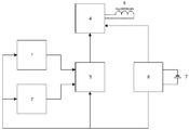
- the electronic probe shown in the drawing contains an inclination angle sensor 1 and a speed sensor 2 of a drilling instrument, which are connected to a control block 3 through outputs.
- the output of the control block 3, which is designed on the basis of a microcontroller, is connected to a transmitting antenna 5 through a power antenna amplifier 4.
- the electronic probe is supplied with a voltage block 6 from a built-in or external source.
- the voltage from the output of block 6 is transferred to all elements of the probe.
- the magnetic transmitting antenna 5 consists of a coil which is arranged on a magnetic conductor with a nanocrystallic structure (not shown in the drawing), which is designed in the form of a rod made of a composite iron alloy HW 414 (hybrid material).
- the rod made of a composite iron alloy HW 414 has a cross section in the form of a circle, but can also have a cross section in the form of a regular polygon, e.g. B. a square, a hexagon or octagon.
- the electronic probe for drill heads works as follows: Before starting work, the electronic probe is fixed inside the drill head for horizontal drilling (not shown in the drawing). Before switching on, the probe is set up in the room in a position that corresponds to switching on the correct frequency, which is specified in the program of the microcontroller of control block 3. When the probe is switched on, the supply voltage from the output of block 6 reaches all elements of the probe.
- the conditions for the formation of the selected frequency which are determined by the values of the output signals from sensors 1 and 2, are checked when the microcontroller of control block 3 is initialized.
- the signals from the sensors 1 and 2 of the angle of inclination and the rotation of the drilling instrument, the sizes of which characterize a spatial position of the probe, come to the inputs of the control block 3, where they are processed and where a signal to excite the magnetic transmitting antenna 5 is generated.
- This signal from the output of the block 3 passes through the power antenna amplifier 4 to the magnetic transmitter antenna 5, which sends a signal to the ground receiver (not shown in the drawing) which characterizes a spatial position of the probe located in the drill head.
- the present electronic probe for drill heads is safer in operation compared to the prototype due to the increased strength of the magnetic conductor of the antenna.
Landscapes
- Physics & Mathematics (AREA)
- Engineering & Computer Science (AREA)
- Life Sciences & Earth Sciences (AREA)
- Geology (AREA)
- General Life Sciences & Earth Sciences (AREA)
- Environmental & Geological Engineering (AREA)
- Geophysics (AREA)
- Mining & Mineral Resources (AREA)
- Electromagnetism (AREA)
- Remote Sensing (AREA)
- Fluid Mechanics (AREA)
- Geochemistry & Mineralogy (AREA)
- General Physics & Mathematics (AREA)
- Earth Drilling (AREA)
Applications Claiming Priority (1)
| Application Number | Priority Date | Filing Date | Title |
|---|---|---|---|
| RU2020101289 | 2020-01-10 |
Publications (1)
| Publication Number | Publication Date |
|---|---|
| EP3848732A1 true EP3848732A1 (fr) | 2021-07-14 |
Family
ID=70110103
Family Applications (1)
| Application Number | Title | Priority Date | Filing Date |
|---|---|---|---|
| EP20167122.9A Withdrawn EP3848732A1 (fr) | 2020-01-10 | 2020-03-31 | Sonde électronique pour têtes de forage |
Country Status (1)
| Country | Link |
|---|---|
| EP (1) | EP3848732A1 (fr) |
Citations (8)
| Publication number | Priority date | Publication date | Assignee | Title |
|---|---|---|---|---|
| US4901069A (en) * | 1987-07-16 | 1990-02-13 | Schlumberger Technology Corporation | Apparatus for electromagnetically coupling power and data signals between a first unit and a second unit and in particular between well bore apparatus and the surface |
| US6008651A (en) * | 1991-03-01 | 1999-12-28 | Digital Control, Inc. | Orientation sensor arrangement and method for use in a system for monitoring the orientation of an underground boring tool |
| EP1679727A1 (fr) | 2003-10-23 | 2006-07-12 | Kabushiki Kaisha Toshiba | Dispositif inductif et procede de fabrication associe |
| US20090179647A1 (en) * | 2008-01-11 | 2009-07-16 | Baker Hughes Incorporated | Method for Building Multi-Component Electromagnetic Antennas |
| US7570223B2 (en) | 2003-01-23 | 2009-08-04 | Vacuumschmelze Gmbh & Co. Kg | Antenna core and method for production of an antenna core |
| US20100244841A1 (en) * | 2009-03-24 | 2010-09-30 | Smith International, Inc. | Non-planar antennae for directional resistivity logging |
| JP2012105092A (ja) | 2010-11-10 | 2012-05-31 | Nakagawa Special Steel Co Inc | アンテナコア及びそれを用いたアンテナ、並びにアンテナコアの製造方法 |
| RU163669U1 (ru) | 2016-02-01 | 2016-07-27 | Александр Леонидович Наговицын | Электронный зонд с управляемым по частоте режимом работы, размещаемый в головке бурового инструмента |
-
2020
- 2020-03-31 EP EP20167122.9A patent/EP3848732A1/fr not_active Withdrawn
Patent Citations (8)
| Publication number | Priority date | Publication date | Assignee | Title |
|---|---|---|---|---|
| US4901069A (en) * | 1987-07-16 | 1990-02-13 | Schlumberger Technology Corporation | Apparatus for electromagnetically coupling power and data signals between a first unit and a second unit and in particular between well bore apparatus and the surface |
| US6008651A (en) * | 1991-03-01 | 1999-12-28 | Digital Control, Inc. | Orientation sensor arrangement and method for use in a system for monitoring the orientation of an underground boring tool |
| US7570223B2 (en) | 2003-01-23 | 2009-08-04 | Vacuumschmelze Gmbh & Co. Kg | Antenna core and method for production of an antenna core |
| EP1679727A1 (fr) | 2003-10-23 | 2006-07-12 | Kabushiki Kaisha Toshiba | Dispositif inductif et procede de fabrication associe |
| US20090179647A1 (en) * | 2008-01-11 | 2009-07-16 | Baker Hughes Incorporated | Method for Building Multi-Component Electromagnetic Antennas |
| US20100244841A1 (en) * | 2009-03-24 | 2010-09-30 | Smith International, Inc. | Non-planar antennae for directional resistivity logging |
| JP2012105092A (ja) | 2010-11-10 | 2012-05-31 | Nakagawa Special Steel Co Inc | アンテナコア及びそれを用いたアンテナ、並びにアンテナコアの製造方法 |
| RU163669U1 (ru) | 2016-02-01 | 2016-07-27 | Александр Леонидович Наговицын | Электронный зонд с управляемым по частоте режимом работы, размещаемый в головке бурового инструмента |
Similar Documents
| Publication | Publication Date | Title |
|---|---|---|
| DE102008048476A1 (de) | Magnetresonanzanlage mit Orientierungserfassung von Hilfsmitteln | |
| DE4004485A1 (de) | Vorrichtung zur herstellung von bohrloechern mit hinterschneidung | |
| DE4027020A1 (de) | Verfahren und vorrichtung zur feststellung des vorhandenseins von metallischen bewehrungselementen in der umgebung von bohrloechern in beton-bauteilen | |
| DE4204644C2 (de) | Vorrichtung zur Einstellung eines Werkzeuganschlags in einer Werkzeugspindel | |
| DE102007020172A1 (de) | Vorrichtung und Verfahren zum räumlichen Vermessen von Werkstücken an einer Werkzeugmaschine | |
| DE19531484C2 (de) | Einrichtung zur Einstellung der Lage tragbarer Werkzeuge | |
| DE9114473U1 (de) | Einnietmutter | |
| DE920054C (de) | Vorrichtung zum Beeinflussen der Achslage einer Spule an Spulmaschinen | |
| DE20301106U1 (de) | Vorrichtung zum Befestigen eines Beschleunigungsaufnehmers | |
| DE725620C (de) | Einspannverfahren fuer Probekoerper zur gleichzeitigen Biege- und Verdrehbelastung und Einrichtung zu dessen Durchfuehrung | |
| DE202013104719U1 (de) | Kernbohrständeraufnahme, Kernbohrständer und Kernbohrgerät | |
| DE1926259B2 (de) | Ferrit-Rahmenantenne | |
| DE1473516B2 (de) | Einrichtung zur ermittlung von durch die ganze materialstaerke von metallrohren hindurchgehenden fehlern | |
| DE1573783A1 (de) | Vorrichtung zur Bestimmung der Auslenkung umlaufender Maschinenteile aus elektrisch leitendem Material | |
| DE102022202416A1 (de) | Verfahren zum Betreiben einer Handwerkzeugmaschine | |
| DE1638048C3 (de) | Elektrischer, kontaktloser Kopierfühler für Nachformeinrichtungen an Werkzeugmaschinen | |
| DE935457C (de) | Einrichtung zum Pruefen der Masshaltigkeit der Koerperformen von Bauteilen | |
| EP0463509A1 (fr) | Etalon de défauts pour un capteur rotatif d'inspection interne | |
| DE3342561A1 (de) | Schlauch aus gummi zum traenken von gestein ueber ein bohrloch | |
| DE1473516C3 (de) | Einrichtung zur Ermittlung von durch die ganze Materialstärke von Metallrohren hindurchgehenden Fehlern | |
| DE532161C (de) | Isolatorkopf | |
| DE2048174C (de) | Vorrichtung zur Durchführung eines Verfahrens zum nachträglichen Justieren eines in einem abgeschlossenen Gehäuse angeord neten magnetisch betätigbaren Ankers | |
| DE742447C (de) | Fassung fuer ein elektrisches Entladungsgefaess | |
| DE1718547U (de) | Parallelschraubstock mit im schraubstockkoerper um eine horizontale achse drehbaren und feststellbaren backenarmen. | |
| DE2547581A1 (de) | Klebeanker und verfahren zum verlegen von klebeankern |
Legal Events
| Date | Code | Title | Description |
|---|---|---|---|
| PUAI | Public reference made under article 153(3) epc to a published international application that has entered the european phase |
Free format text: ORIGINAL CODE: 0009012 |
|
| STAA | Information on the status of an ep patent application or granted ep patent |
Free format text: STATUS: THE APPLICATION HAS BEEN PUBLISHED |
|
| AK | Designated contracting states |
Kind code of ref document: A1 Designated state(s): AL AT BE BG CH CY CZ DE DK EE ES FI FR GB GR HR HU IE IS IT LI LT LU LV MC MK MT NL NO PL PT RO RS SE SI SK SM TR |
|
| STAA | Information on the status of an ep patent application or granted ep patent |
Free format text: STATUS: REQUEST FOR EXAMINATION WAS MADE |
|
| 17P | Request for examination filed |
Effective date: 20220114 |
|
| RBV | Designated contracting states (corrected) |
Designated state(s): AL AT BE BG CH CY CZ DE DK EE ES FI FR GB GR HR HU IE IS IT LI LT LU LV MC MK MT NL NO PL PT RO RS SE SI SK SM TR |
|
| TPAC | Observations filed by third parties |
Free format text: ORIGINAL CODE: EPIDOSNTIPA |
|
| STAA | Information on the status of an ep patent application or granted ep patent |
Free format text: STATUS: EXAMINATION IS IN PROGRESS |
|
| 17Q | First examination report despatched |
Effective date: 20230112 |
|
| STAA | Information on the status of an ep patent application or granted ep patent |
Free format text: STATUS: THE APPLICATION HAS BEEN WITHDRAWN |
|
| 18W | Application withdrawn |
Effective date: 20230327 |