EP3849101A1 - Système et procédé d'annulation avec électronique d'antenne anti-brouillage - Google Patents
Système et procédé d'annulation avec électronique d'antenne anti-brouillage Download PDFInfo
- Publication number
- EP3849101A1 EP3849101A1 EP21150763.7A EP21150763A EP3849101A1 EP 3849101 A1 EP3849101 A1 EP 3849101A1 EP 21150763 A EP21150763 A EP 21150763A EP 3849101 A1 EP3849101 A1 EP 3849101A1
- Authority
- EP
- European Patent Office
- Prior art keywords
- weight vector
- nullforming
- antenna
- nulls
- output signal
- Prior art date
- Legal status (The legal status is an assumption and is not a legal conclusion. Google has not performed a legal analysis and makes no representation as to the accuracy of the status listed.)
- Pending
Links
Images

Classifications
-
- H—ELECTRICITY
- H04—ELECTRIC COMMUNICATION TECHNIQUE
- H04B—TRANSMISSION
- H04B7/00—Radio transmission systems, i.e. using radiation field
- H04B7/02—Diversity systems; Multi-antenna system, i.e. transmission or reception using multiple antennas
- H04B7/04—Diversity systems; Multi-antenna system, i.e. transmission or reception using multiple antennas using two or more spaced independent antennas
- H04B7/06—Diversity systems; Multi-antenna system, i.e. transmission or reception using multiple antennas using two or more spaced independent antennas at the transmitting station
- H04B7/0613—Diversity systems; Multi-antenna system, i.e. transmission or reception using multiple antennas using two or more spaced independent antennas at the transmitting station using simultaneous transmission
- H04B7/0615—Diversity systems; Multi-antenna system, i.e. transmission or reception using multiple antennas using two or more spaced independent antennas at the transmitting station using simultaneous transmission of weighted versions of same signal
- H04B7/0617—Diversity systems; Multi-antenna system, i.e. transmission or reception using multiple antennas using two or more spaced independent antennas at the transmitting station using simultaneous transmission of weighted versions of same signal for beam forming
-
- H—ELECTRICITY
- H01—ELECTRIC ELEMENTS
- H01Q—ANTENNAS, i.e. RADIO AERIALS
- H01Q3/00—Arrangements for changing or varying the orientation or the shape of the directional pattern of the waves radiated from an antenna or antenna system
- H01Q3/26—Arrangements for changing or varying the orientation or the shape of the directional pattern of the waves radiated from an antenna or antenna system varying the relative phase or relative amplitude of energisation between two or more active radiating elements; varying the distribution of energy across a radiating aperture
- H01Q3/2605—Array of radiating elements provided with a feedback control over the element weights, e.g. adaptive arrays
- H01Q3/2611—Means for null steering; Adaptive interference nulling
- H01Q3/2617—Array of identical elements
-
- H—ELECTRICITY
- H04—ELECTRIC COMMUNICATION TECHNIQUE
- H04B—TRANSMISSION
- H04B7/00—Radio transmission systems, i.e. using radiation field
- H04B7/02—Diversity systems; Multi-antenna system, i.e. transmission or reception using multiple antennas
- H04B7/04—Diversity systems; Multi-antenna system, i.e. transmission or reception using multiple antennas using two or more spaced independent antennas
- H04B7/08—Diversity systems; Multi-antenna system, i.e. transmission or reception using multiple antennas using two or more spaced independent antennas at the receiving station
- H04B7/0837—Diversity systems; Multi-antenna system, i.e. transmission or reception using multiple antennas using two or more spaced independent antennas at the receiving station using pre-detection combining
- H04B7/0842—Weighted combining
- H04B7/086—Weighted combining using weights depending on external parameters, e.g. direction of arrival [DOA], predetermined weights or beamforming
Definitions
- Modern antennas often include active electronically scanned arrays (AESAs) including a plurality of antenna elements.
- AESAs active electronically scanned arrays
- digital processing techniques allows for modern antennas to mitigate effects of jamming signals, and improve antenna performance.
- Anti-jamming (AJ) signal processing is a jammer nulling technique that can be done in time domain or frequency domain.
- Two traditional modes of operation in anti-jamming antenna electronics (AJAE) are the nulling mode which minimizes jamming signal power according to certain criterion of optimality, and the beamforming mode which constrains the AJ processing to maintain a specified gain in the direction of signal of interest while minimizing jamming signal power.
- nulling technique is an adaptive approach that only depends on signal conditions, and therefore is lacking the flexibility to perform any additional nulling if needed.
- This disclosure provides a new technique in AJ processing to create a null (nullforming) in the user-specified direction while maintaining its AJ capability. Therefore, the nullforming technique in this disclosure is a generalized nulling approach that simultaneously performs adaptive nulling which depends on signal conditions, and constrained nulling which gives user the option to create a null in a specified direction regardless of signal conditions.
- the antenna system includes an antenna array including two or more antenna elements, wherein the antenna array configured to receive one or more signals.
- the antenna system further includes one or more signal processors configured to: determine a beamforming weight vector ( W bf ) for the antenna array; determine a first seeding weight vector ( W seed 1 ) for the antenna array, wherein the first seeding weight vector ( W seed 1 ) comprises at least one of a first nulling weight vector ( W nul 1 ) or a second beamforming weight vector ( W bf ) different from the beamforming weight vector ( W bf ); determine a first nullforming adjustment factor ( ⁇ 1 ) for the antenna array; calculate a first nullforming weight vector ( W nf 1 ) based on at least the beamforming weight vector ( W bf ), the first seeding weight vector ( W seed 1 ), and the first nullforming adjustment factor ( ⁇ 1 ); and form a first antenna pattern based on the first nullforming weight vector ( W bf )
- the first set of one or more nulls include one or more constrained nulls generated in a specified direction.
- the first set of one or more nulls include one or more adaptive nulls generated in a direction of one or more received jamming signals.
- the first set of one or more nulls further include one or more sympathetic nulls generated in one or more directions other than the direction of the one or more received jamming signals.
- the first nullforming adjustment factor ( ⁇ 1 ) is determined based on at least one of the beamforming weight vector ( W bf ) or the first seeding weight vector.
- the one or more signal processors include one or more digital signal processors.
- the antenna system further includes a receiver configured to: receive the first AE output signal; determine a gain of the first AE output signal in a determined nulling direction; and determine a nulling effectiveness metric of the first nullforming weight vector ( W nf 1 ) based on the gain of the first AE output signal.
- the receiver is further configured to: determine one or more characteristics of the one or more signals based on the first AE output signal, wherein the one or more characteristics of the one or more signals comprise a direction of the one or more signals.
- the one or more signal processors are further configured to: determine a second seeding weight vector ( W s eed 2 ) for the antenna array; determine a second nullforming adjustment factor ( ⁇ 2 ) for the antenna array; calculate a second nullforming weight vector ( W nf 2 ) based on at least the beamforming weight vector ( W bf ), the second seeding weight vector ( W seed 2 ), and the second nullforming adjustment factor ( ⁇ 2 ); and form a second antenna pattern based on the second nullforming weight vector ( W nf 2 ) to generate a second AE output signal, wherein the second antenna pattern generates a second set of one or more nulls.
- the first set of one or more nulls include a first constrained null generated in a defined direction
- the second set of one or more nulls generate a second constrained null in the defined direction
- the first set of one or more nulls and the second set of one or more nulls are generated simultaneously.
- the antenna system comprising a receiver configured to: evaluate the first AE output signal; evaluate the second AE output signal; and compare the first AE output signal and the second AE output signal to determine one or more characteristics of the one or more signals.
- the one or more characteristics of the one or more signals include a direction of the one or more signals.
- evaluating the first AE output signal includes determining a first nulling effectiveness of the first nullforming weight vector ( W nf 1 ), and evaluating the second AE output signal includes determining a second nulling effectiveness of the second nullforming weight vector ( W nf 2 ).
- a method for nullforming includes: receiving one or more signals with an antenna array including one or more antenna elements; determining a beamforming weight vector ( W bf ) for the antenna array; determining a seeding weight vector ( W seed ) for the antenna array, wherein the seeding weight vector ( W seed ) includes at least one of a nulling weight vector ( W nul ) or an additional beamforming weight vector ( W bf 2 ) different from the beamforming weight vector ( W bf ); determining a nullforming adjustment factor ( ⁇ ) for the antenna array; calculating the nullforming weight vector ( W nf ) based on at least the beamforming weight vector ( W bf ), seeding weight vector ( W seed ), and the nullforming adjustment factor ( ⁇ ); and forming an antenna pattern based on the nullforming weight vector ( W nf ), wherein the antenna pattern generates a first set of one or more nulls.
- a letter following a reference numeral is intended to reference an embodiment of the feature or element that may be similar, but not necessarily identical, to a previously described element or feature bearing the same reference numeral (e.g., 1, 1a, 1b).
- reference numeral e.g. 1, 1a, 1b
- Such shorthand notations are used for purposes of convenience only and should not be construed to limit the disclosure in any way unless expressly stated to the contrary.
- any reference to “one embodiment” or “some embodiments” means that a particular element, feature, structure, or characteristic described in connection with the embodiment is included in at least one embodiment disclosed herein.
- the appearances of the phrase “in some embodiments” in various places in the specification are not necessarily all referring to the same embodiment, and embodiments may include one or more of the features expressly described or inherently present herein, or any combination of sub-combination of two or more such features, along with any other features which may not necessarily be expressly described or inherently present in the instant disclosure.
- Antenna array processing techniques for inserting reception pattern nulls in a specified direction or adaptively in the direction of jamming signals have been known in the art.
- the ability to insert a deep null in a specified direction while maintaining deep adaptive nulls in the direction of jamming signals has proven to be difficult to achieve.
- the techniques of the present disclosure address these shortfalls of previous approaches and allow for the generation of a deep null in a specified direction while maintaining the adaptive null depth in the direction of jamming signals.
- the techniques of the present disclosure address shortfalls caused by the sympathetic nulls in the adaptive nulling process.
- Embodiments of the present disclosure are directed to an antenna electronics (AE) configured to generate one or more nulls based on a calculated nullforming weight vector ( W nf ).
- the one or more nulls generated may include a constrained null in a specified direction and, if present, one or more adaptive nulls in the direction of jamming signals.
- the nullforming weight vector ( W nf ) may be based on, at least in part, a nulling weight vector ( W nul ) or a beamforming weight vector ( W bfn ) for a direction other than the constrained null direction, which is considered a seeding weight vector later in the disclosure, a beamforming weight vector ( W bf ) in the same direction as the constrained null, and a nullforming adjustment factor ( ⁇ ). Additional embodiments of the present disclosure are directed to a method for modifying the nulling weight vector ( W nul ) to mitigate the presence of undesired sympathetic nulls within the nullforming reception pattern.
- embodiments of the present disclosure may enable suppression and/or elimination of jamming signals while forming a null in a user specified direction (e.g., constrained nulls). Additionally, embodiments of the present disclosure may allow for adjustable depth of constrained nulls, and for the use of multiple seeding weight vectors to create multiple nullforming instances in the same direction. By enabling the ability to create multiple nullforming instances in the same constrained null direction, the system and method of the present disclosure may allow for unintended sympathetic nulls to be avoided, and may allow for more robust nullforming and thus the improved direction-of-arrival determination for received signals.
- the term "instance” may be used to refer to the process of antenna electronics (AE) calculating weight vectors for an AJ mode of operation (e.g., nulling, beamforming, nullforming) based on a block of samples, and a receiver processing a signal of interest upon which the determined weight vectors are applied.
- AE antenna electronics
- multiple “nullforming instances” may refer to multiple iterations of the following steps: (1) AE calculating a new seeding weight vector, (2) AE computing a new nullforming weight vector based on the latest calculated seeding weight vector, and (3) a receiver determining the calculated nullforming weight vector's impact on the signal of interest.
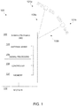
- FIG. 1 illustrates an antenna system 100 including antenna electronics (AE 102) for performing nullforming, in accordance with one or more embodiments of the present disclosure.
- the antenna system 100 may include, but is not limited to, AE 102 configured to perform anti-jam (AJ) nullforming functions.
- AE 102 antenna electronics
- AJ anti-jam
- the AE 102 of the antenna system 100 may include, but is not limited to, an antenna array 104, one or more signal processors 106, a controller 108, and a memory 110.
- the antenna system 100 may further include a receiver 112 configured to perform signal processing of the output of the AE 102.
- the receiver 112 may be configured for processing signals of interest after AJ operation by the AE 102, and may therefore be regarded as an instrument for AJ performance assessment.
- antenna array 104 may include a plurality of antenna elements.
- the plurality of antenna elements may be arranged in any manner known in the art.
- the antenna array 102 may include at least two antenna elements regardless of its geometry. It is assumed hereafter that the antenna array has a total of M elements.
- the plurality of antenna elements of the antenna array 104 are configured to receive one or more signals 103a, 103b from one or more transmitting devices 101a, 101b.
- the antenna array 104 may be configured to receive a first signal 103a from a first transmitting device 101a, and a second signal 103b from a second transmitting device 101b.
- the antenna array 104 may be configured to receive any number of signals 103a-103n from any number of transmitting devices 101a-101n.
- the signals 103a, 103b may be received from varying directions. For instance, as shown in FIG. 1 , the first signal 103a may be received from a first direction, and the second signal 103b may be received from a second direction different from the first direction. It is contemplated herein that the directions from which signals 103a, 103b are received may be determined according to any frame of reference known in the art including, but not limited to, boresight.
- the transmitting devices 101a, 101b may include any transmitting device known in the art including, but not limited to, jamming devices, satellites, radios, beacons, and the like.
- the second transmitting device 101b may include a jamming device, such that the signals 103b received from the jamming device (e.g., second transmitting device 101b) may be regarded as jamming signals 103b.
- embodiments of the present disclosure are directed to the AE 102 and a method for operating the AE 102 configured to suppress, or eliminate, the effects of jamming signals.
- the antenna array 104 may be communicatively coupled to the one or more signal processors 106, the controller 108, and the memory 110.
- AE 102 may be configured to receive the one or more signals 103a, 103b and perform one or more analog-to-digital conversion (ADC) operations on the received analog signals in order to generate digital signals.
- ADC analog-to-digital conversion
- the AE 102 e.g., antenna array 104, signal processors 106, controller 108) may include one or more ADC devices.
- the one or more signal processors 106 may receive the signals 103a, 103b (e.g., digitized signals 103a, 103b) from the antenna array 104.
- the one or more signal processors 106 may be configured to execute a set of program instructions stored in memory 110, the set of program instructions configured to cause the one or more signal processors 106 to carry out the various steps of the present disclosure. It is contemplated herein that the one or more signal processors 106 and controller 108 may include processing and/or logic components configured to carry out the various functions of the AE 102.
- the one or more signal processors 106 may include separate hardware/components from the controller 108, or may include a module executable by the controller 108.
- the one or more signal processors 106 will be shown and described as separate components which are configured to carry out a majority of the steps/functions of the present disclosure.
- the controller 108 may be understood to include processing functionality for the AE 102 which utilizes the output of the signal processors 106, and which communicatively couples the components of the AE 102 to additional and/or alternative electronic components.
- the one or more signal processors 106 may be configured to: determine a beamforming weight vector ( W bf ) for the antenna array; determine a nulling weight vector ( W nul ) for the antenna array; determine the nullforming adjustment factor ( ⁇ ) for the antenna array; calculate a nullforming weight vector ( W nf ) based on at least the beamforming weight vector ( W bf ), the nulling weight vector ( W nul ), and the nullforming adjustment factor ( ⁇ ).
- W bf beamforming weight vector
- ⁇ nulling weight vector
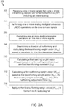
- FIGS. 2A-2B illustrate portions of a method 200 for nullforming with the antenna electronics (AE) 102, in accordance with one or more embodiments of the present disclosure. It is noted herein that the steps of method 200 may be implemented all or in part by the antenna system 100/AE 102. It is further recognized, however, that the method 200 is not limited to the antenna system 100/AE 102 in that additional or alternative system-level embodiments may carry out all or part of the steps of method 200.
- one or more signals 103 are received.
- the antenna array 104 of the AE 102 may receive one or more signals 103 from one or more transmitting devices 101.
- Signals 103 received by the antenna array 104 may include desired/legitimate signals intended to be received by the receiver 112, as well as undesired jamming signals 103.
- the antenna array 104 may receive one or more jamming signals 103 from one or more jamming devices.
- a step 204 one or more analog-to-digital conversion (ADC) operations are performed on the composite of received signals 103 passing through each antenna element of the antenna array 104 and associated radio-frequency (RF) channel electronics.
- ADC analog-to-digital conversion
- the AE 102, antenna array 104, and/or signal processors 106 may include one or more ADC devices configured to perform ADC operations on the received signals 103.
- baseline processing e.g., digital processing operations
- the one or more digital processing operations may include any digital processing operations known in the art.
- the one or more digital processing operations may include processing ADC samples in either time or frequency domains, and estimation of the M-by-M covariance matrix (or matrices) accordingly, where M is the number of antenna elements within the antenna array 104.
- a direction for desired nullforming is determined (e.g., constrained direction), and a beamforming weight vector ( W bf ) for the determined/constrained direction is determined.
- the), the beamforming weight vector ( W bf ) for the determined/constrained direction is determined based on a beamforming constraint for the specified nullforming direction ( r xd ) (e.g., determined/constrained direction),
- the one or more signal processors 106 may be configured to identify a direction of received jamming signals 103, and identify the direction of the jamming signals as the determined/constrained direction for nullforming.
- the signal processors 106 may be configured calculate the beamforming weight vector ( W bf ) for the antenna array 104 for a specified direction commanded by the receiver 112.
- the beamforming weight vector ( W bf ) may be managed by controller 108 and stored in memory 110.
- a first seeding weight vector ( W seed 1 ) is calculated based on a first nulling constraint ( r 01 ) or a first beamforming constraint ( r xd 1 ).
- the first seeding weight vector ( W seed 1 ) includes a first nulling weight vector ( W nul 1 )
- the first seeding weight vector ( W seed 1 ) includes a nondirectional weight vector.
- the first seeding weight vector ( W seed 1 ) includes a beamforming weight vector ( W bf 1 )
- the first seeding weight vector ( W seed 1 ) includes a directional weight vector.
- the directional seeding weight vector ( W seed 1 ) must be for a direction other than the determined/constrained direction for nullforming.
- the seeding weight vector ( W seed 1 ) may be managed by controller 108 and stored in memory 110.
- a first nullforming weight vector ( W nf 1 ) is determined.
- a nullforming weight vector ( W nf ) may be calculated based on a beamforming weight vector ( W bf ), the seeding weight vector ( W seed 1 ) (e.g., first nulling weight vector ( W nul 1 ), or first beamforming weight vector ( W bf 1 )), and a nullforming adjustment factor ( ⁇ 1 ).
- the one or more signal processors 106 may be configured to determine the first nullforming adjustment factor ( ⁇ 1 ) for the antenna array 104.
- a nullforming adjustment factor ( ⁇ 1 ) may be determined/chosen based on the beamforming weight vector ( W bf ) and the first seeding weight vector ( W seed 1 ).
- the first nullforming weight vector ( W nf 1 ) is applied to form a first AE output signal.
- the one or more signal processors 106 generate one or more control signals configured to apply the first nullforming weight vector ( W nf 1 ) to the digitized output of the antenna array 104 in order to generate a first antenna pattern.
- the signal processors 106 may be configured to form a first antenna pattern based on the first nullforming weight vector ( W nf 1 ). The first antenna pattern may subsequently be used to modify the digitized signals of the antenna array 104 and generate the first AE output signal.
- the term "AE output signal” may be regarded as the digitized signals from the antenna array 104 modified by the respective nullforming weight vector ( W nf 1 )/antenna pattern.
- the first AE output signal may be regarded as the digitized signals from the antenna array 104 modified by the first antenna pattern, which was generated by the first nullforming weight vector ( W nf 1 ).
- the first antenna pattern generated by the first nullforming weight vector ( W nf 1 ) may generate a first set of one or more nulls.
- the first set of one or more nulls may include one or more constrained nulls generated in a specified direction other than the direction of received jamming signals 103 (e.g., direction of nullforming determined in step 208).
- each nullforming weight vector ( W nf 1 ) may be configured to generate one constrained null in the specified direction.
- the first set of one or more nulls may further include one or more adaptive nulls generated in a direction of received jamming signals 103 (if jamming signals 103 are present).
- the first set of one or more nulls may further include one or more sympathetic nulls generated in one or more directions other than the direction of the one or more received jamming signals 103 and/or the direction of the generated constrained nulls.
- the receiver 112 may be configured to evaluate/process the AE output signal.
- the receiver 112 may be configured to evaluate the first AE output signal (e.g., digitized signals as modified by the first nullforming weight vector (( W nf 1 )/first antenna pattern).
- the receiver 112 may be configured to determine one or more characteristics of the received signals 103a, 103b, the first set of nulls, and the like. Characteristics which may be determined may include, but are not limited to, signal power, signal direction estimation (e.g., signal direction relative to boresight), and the like.
- evaluating AE output signals may include evaluating power, gain, and phase of the received signals 103a, 103b as modified by the first nullforming weight vector ( W nf 1 ).
- the receiver 112 may be configured to receive the first AE output signal (e.g., digitized signals of antenna array 104 modified by the first nullforming weight vector (( W nf 1 )/first antenna pattern), and determine a gain/power of the first AE output signal in the determined nulling direction. The receiver 112 may then be configured to determine a nulling effectiveness metric of the first nullforming weight vector ( W nf 1 ) based on the determined gain/power of the first AE output signal.
- the first AE output signal e.g., digitized signals of antenna array 104 modified by the first nullforming weight vector (( W nf 1 )/first antenna pattern
- the receiver 112 may then be configured to determine a nulling effectiveness metric of the first nullforming weight vector ( W nf 1 ) based on the determined gain/power of the first AE output signal.
- a nulling metric may include any metric indicative of an effectiveness of the one or more constrained nulls of the first set of one or more nulls of the first antenna pattern (e.g., first nullforming weight vector ( W nf 1 )) in suppressing and/or eliminating the intended signal 103b.
- higher nulling metrics may be indicative of higher nulling effectiveness/performance (e.g., high effectiveness in suppressing the intended signal 103b, "deeper” null)
- lower nulling metrics may be indicative of lower nulling effectiveness/performance (e.g., low effectiveness in suppressing the intended signal 103b, "shallower” null).
- the effectiveness/efficiency of a nullforming weight vector ( W nf ) may be determined by comparing the gain/power of signals 103 intended to be nulled to signal power threshold values.
- the first nullforming weight vector ( W nf ) may be generated and applied in an effort to null jamming signals 103 coming from a determined/constrained direction.
- the receiver 112 may receive the AE output signal, determine the resulting gain/power of the intended signal 103. Accordingly, the signal power and/or detectability of signals 103 by the receiver 112 after the application of nullforming weight vectors ( W nf ) may be used as a performance indicator of the nullforming processing.
- the efficiency of a particular nullforming weight vector ( W nf ) may be used to determine one or more characteristics of a signal 103. For example, by comparing signal powers of received signals 103 before and after the application of a nullforming weight vector ( W nf ), the signal processors 106 and/or receiver 112 may be configured to determine a direction/angle of arrival of the received signals 103.
- the method 200 may terminate at step 216. In additional and/or alternative embodiments, the method 200 may proceed to in order to generate additional nullforming weight vectors ( W nf ). For example, if it is determined that the first nullforming weight vector ( W nf 1 ) does not sufficiently null identified jamming signals 103, the method 200 may proceed to step 218 in order to generate additional nullforming weight vectors ( W nf 2 , W nf 3 , ..., W nfn )
- the receiver 112 may extend baseline processing of method 200 to make nullforming more effective.
- multiple unique nullforming reception patterns may be generated by changing only the seeding weight vector and the nullforming adjustment factor ( ⁇ 1 ).
- the seeding weight vector can be a nulling weight vector ( W nul ) readily available in AJ nulling, or a beamforming weight vector ( W bf ) for any direction other than the direction for nullforming.
- a second seeding weight vector ( W s eed 2 ) is calculated based on a second nulling constraint ( r 02 ) and/or a second beamforming constraint ( r xd 2 ).
- the second seeding weight vector ( W seed 1 ) may be set to a second nulling weight vector ( W nul 2 ), based on a second nulling constraint ( r 02 ), or an additional beamforming weight vector ( W bf2 ), based on a second beamforming constraint ( r xd2 ) for a direction other than the nullforming direction.
- the second nulling constraint ( r 02 ) may include a column vector of M complex values, where M is the number of antenna elements within the antenna array 104.
- the nulling constraint vector ( r 02 ) may be set to all zeros with the exception of a single element that is set to 1.
- the resulting second seeding weight vector ( W s eed 2 ) is managed by controller 108 and stored in memory 110.
- a second nullforming weight vector ( W nf 2 ) is determined.
- the second nullforming weight vector ( W nf 2 ) may be calculated based on the beamforming weight vector ( W bf ), the second seeding weight vector ( W seed 2 ), and a second nullforming adjustment factor ( ⁇ 2 ).
- the second nullforming weight vector ( W nf 2 ) is applied to form a second AE output signal.
- the one or more signal processors 106 may be configured to generate one or more control signals configured to apply the second nullforming weight vector ( W nf 2 ) to the digitized output of the antenna array 104 in order to generate a second antenna pattern.
- the signal processors 106 may be configured to form a second antenna pattern based on the second nullforming weight vector ( W nf 2 ).
- the second antenna pattern may subsequently be used to modify the digitized signals of the antenna array 104 and generate the second AE output signal.
- the second AE output may be regarded as the digitized signals from the antenna array 104 modified by the second antenna pattern, which was generated by the second nullforming weight vector ( W nf 2 ).
- the second antenna pattern generated by the second nullforming weight vector ( W nf 2 ) may generate a second set of one or more nulls.
- the second set of one or more nulls may include one or more constrained nulls generated in a specified direction (e.g., direction of nullforming determined in step 208), one or more adaptive nulls generated in the direction of received jamming signals 103, and/or one or more sympathetic nulls generated in one or more directions other than the direction of the one or more received jamming signals and/or the direction of the generated constrained nulls.
- the second set of nulls may include one or more adaptive nulls generated in a direction of one or more received jamming signals 103.
- the second set of nulls may be generated in different directions than the first set of nulls.
- the first and second sets of nulls may generate constrained nulls in the same direction.
- the first set of one or more nulls include a first constrained null generated in a defined direction, and the second set of one or more nulls generate a second constrained null in the defined direction.
- the second set of one or more nulls include one or more sympathetic nulls in directions other than those associated with jamming signals 103 and in directions different from the directions of the sympathetic nulls generated in the first set of one or more nulls.
- the signal processors 106 may be configured to generate the first set of nulls and the second set of nulls simultaneously or sequentially.
- the receiver 112 may be configured to evaluate/process the second AE output signal.
- the receiver 112 may be configured to evaluate the second AE output signal (e.g., digitized signals as modified by the second nullforming weight vector ( W nf 2 )/second antenna pattern).
- the receiver 112 may be configured to evaluate/process the AE output signal.
- the receiver 112 may be configured to evaluate the first AE output signal (e.g., digitized signals as modified by the first nullforming weight vector (W nf 1 )/first antenna pattern).
- the receiver 112 may be configured to receive the second AE output signal (e.g., digitized signals of antenna array 104 modified by the second nullforming weight vector (W nf 2 )/second antenna pattern), and determine a gain/power of the second AE output signal in the determined/constrained nulling direction.
- the receiver 112 may then be configured to determine a nulling effectiveness metric of the second nullforming weight vector ( W nf 2 ) based on the determined gain/power of the second AE output signal.
- a nulling metric may include any metric indicative of an effectiveness of the constrained nulls of the second antenna pattern (e.g., second nullforming weight vector ( W nf 2 )) in suppressing and/or eliminating the intended signal 103b.
- the receiver 112 may be configured to evaluate each of the first AE output signal and the second AE output signal, and compare the respective AE output signals. By evaluating and comparing the AE output signals, the receiver 112 may be configured to determine one or more characteristics of the signals 103, transmitting devices 101, and/or generated nulls. For example, the first nullforming weight vector ( W nf 1 ) may generate a first set of one or more nulls in a first direction, and the second nullforming weight vector ( W nf 2 ) may generate second set of one or more nulls in a second direction.
- Evaluation and comparison of the first AE output signal and the second AE output signal may reveal a first nulling effectiveness metric associated with the first nullforming weight vector ( W nf 1 ) (e.g., first AE output signal), and a second nulling effectiveness metric associated with the second nullforming weight vector ( W nf 2 ) (e.g., second AE output signal).
- the second nulling effectiveness metric may be greater than the first nulling effectiveness metric.
- steps 216-220 may be repeated any n number of times to generate n number of nullforming weight vectors ( W nfn ).
- the signal processors 106 and/or receiver 112 may further mitigate sympathetic nulls in the nullforming reception pattern, and make the constrained null more robust, thereby resulting in improved signal characterization and angle of arrival estimation.
- the signal processors 106, controller 108, and/or receiver 112 provide processing functionality antenna system 100 and can include any number of processors, micro-controllers, circuitry, field programmable gate array (FPGA) or other processing systems, and resident or external memory for storing data, executable code, and other information accessed or generated by the antenna system 100.
- the signal processors 106, controller 108, and/or receiver 112 can execute one or more software programs embodied in a non-transitory computer readable medium (e.g., memory 110) that implement techniques described herein.
- the signal processors 106, controller 108, and/or receiver 112 are not limited by the materials from which it is formed or the processing mechanisms employed therein and, as such, can be implemented via semiconductor(s) and/or transistors (e.g., using electronic integrated circuit (IC) components), and so forth.
- IC electronic integrated circuit
- the memory 110 can be an example of tangible, computer-readable storage medium that provides storage functionality to store various data and/or program code associated with operation of the antenna array 104, signal processors 106, controller 108, and/or receiver 112 such as software programs and/or code segments, or other data to instruct the signal processors 106 and/or controller 108, and possibly other components of the antenna system 100, to perform the functionality described herein.
- the memory 110 can store data, such as a program of instructions for operating the antenna system 100, including its components (e.g., antenna array 104, signal processors 106, controller 108, receiver 112, etc.), and so forth.
- the memory 110 can be integral with the signal processors 106, controller 108, and/or receiver 112, can comprise stand-alone memory, or can be a combination of both.
- Some examples of the memory 110 can include removable and non-removable memory components, such as random-access memory (RAM), read-only memory (ROM), flash memory (e.g., a secure digital (SD) memory card, a mini-SD memory card, and/or a micro-SD memory card), solid-state drive (SSD) memory, magnetic memory, optical memory, universal serial bus (USB) memory devices, hard disk memory, external memory, and so forth.
- RAM random-access memory
- ROM read-only memory
- flash memory e.g., a secure digital (SD) memory card, a mini-SD memory card, and/or a micro-SD memory card
- SSD solid-state drive
- magnetic memory magnetic memory
- optical memory optical memory
- USB universal serial bus
- embodiments of the methods disclosed herein may include one or more of the steps described herein. Further, such steps may be carried out in any desired order and two or more of the steps may be carried out simultaneously with one another. Two or more of the steps disclosed herein may be combined in a single step, and in some embodiments, one or more of the steps may be carried out as two or more sub-steps. Further, other steps or sub-steps may be carried in addition to, or as substitutes to one or more of the steps disclosed herein.
Landscapes
- Engineering & Computer Science (AREA)
- Computer Networks & Wireless Communication (AREA)
- Signal Processing (AREA)
- Variable-Direction Aerials And Aerial Arrays (AREA)
- Radio Transmission System (AREA)
Applications Claiming Priority (1)
| Application Number | Priority Date | Filing Date | Title |
|---|---|---|---|
| US16/737,116 US11374636B2 (en) | 2020-01-08 | 2020-01-08 | System and method for nullforming with anti-jam antenna electronics |
Publications (1)
| Publication Number | Publication Date |
|---|---|
| EP3849101A1 true EP3849101A1 (fr) | 2021-07-14 |
Family
ID=74125113
Family Applications (1)
| Application Number | Title | Priority Date | Filing Date |
|---|---|---|---|
| EP21150763.7A Pending EP3849101A1 (fr) | 2020-01-08 | 2021-01-08 | Système et procédé d'annulation avec électronique d'antenne anti-brouillage |
Country Status (2)
| Country | Link |
|---|---|
| US (1) | US11374636B2 (fr) |
| EP (1) | EP3849101A1 (fr) |
Families Citing this family (3)
| Publication number | Priority date | Publication date | Assignee | Title |
|---|---|---|---|---|
| US12176980B2 (en) * | 2020-09-16 | 2024-12-24 | Telefonaktiebolaget Lm Ericsson (Publ) | Technique for dual-polarized beamforming |
| US12184409B1 (en) * | 2023-06-30 | 2024-12-31 | Bae Systems Information And Electronic Systems Integration Inc. | Difference-based jammer detection system |
| US12601845B2 (en) | 2024-02-21 | 2026-04-14 | Bae Systems Information And Electronic Systems Integration Inc. | GPS spoofer direction finding and geolocation |
Citations (2)
| Publication number | Priority date | Publication date | Assignee | Title |
|---|---|---|---|---|
| US5371506A (en) * | 1993-07-19 | 1994-12-06 | General Electric Co. | Simultaneous multibeam approach for cancelling multiple mainlobe jammers while preserving monopulse angle estimation accuracy on mainlobe targets |
| WO1998024192A1 (fr) * | 1996-11-26 | 1998-06-04 | Trw Inc. | Systeme de traitement de signaux dans le meme canal |
Family Cites Families (9)
| Publication number | Priority date | Publication date | Assignee | Title |
|---|---|---|---|---|
| US5955987A (en) | 1997-01-28 | 1999-09-21 | Northrop Grumman Corporation | Hybrid radio frequency system with distributed anti-jam capabilities for navigation use |
| US8305265B2 (en) | 2007-05-29 | 2012-11-06 | Toyon Research Corporation | Radio-based direction-finding navigation system using small antenna |
| WO2013043741A1 (fr) | 2011-09-19 | 2013-03-28 | Ohio University | Antenne pour systèmes globaux de navigation par satellites |
| US9612342B2 (en) | 2011-09-20 | 2017-04-04 | Novatel Inc. | GNSS positioning system including an anti-jamming antenna and utilizing phase center corrected carrier |
| US9648502B2 (en) * | 2012-08-15 | 2017-05-09 | Trimble Navigation Limited | System for tailoring wireless coverage to a geographic area |
| US10609568B2 (en) | 2017-04-03 | 2020-03-31 | Novatel Inc. | System and method for determining azimuth of a source of an interfering signal using a beam steering antenna |
| CN111869009B (zh) | 2018-01-21 | 2022-06-21 | 英菲尼朵美有限公司 | 相位阵列抗干扰装置及方法 |
| US10327221B1 (en) * | 2018-05-25 | 2019-06-18 | Apple Inc. | Super-resolution technique for time-of-arrival estimation |
| US11196464B2 (en) * | 2019-09-09 | 2021-12-07 | Qualcomm Incorporated | Beam training in millimeter wave relays using amplify-and-forward transmissions |
-
2020
- 2020-01-08 US US16/737,116 patent/US11374636B2/en active Active
-
2021
- 2021-01-08 EP EP21150763.7A patent/EP3849101A1/fr active Pending
Patent Citations (2)
| Publication number | Priority date | Publication date | Assignee | Title |
|---|---|---|---|---|
| US5371506A (en) * | 1993-07-19 | 1994-12-06 | General Electric Co. | Simultaneous multibeam approach for cancelling multiple mainlobe jammers while preserving monopulse angle estimation accuracy on mainlobe targets |
| WO1998024192A1 (fr) * | 1996-11-26 | 1998-06-04 | Trw Inc. | Systeme de traitement de signaux dans le meme canal |
Also Published As
| Publication number | Publication date |
|---|---|
| US20210211170A1 (en) | 2021-07-08 |
| US11374636B2 (en) | 2022-06-28 |
Similar Documents
| Publication | Publication Date | Title |
|---|---|---|
| EP3849101A1 (fr) | Système et procédé d'annulation avec électronique d'antenne anti-brouillage | |
| Shen et al. | Robust adaptive beamforming based on steering vector estimation and covariance matrix reconstruction | |
| CN107561512B (zh) | 一种脉冲多普勒雷达抗压制式拖曳干扰的极化对消方法 | |
| CN114355293B (zh) | 一种自适应波束生成方法及系统 | |
| KR101274554B1 (ko) | 도래각 추정 방법 및 이를 이용한 배열 안테나 시스템 | |
| Li et al. | Robust adaptive beamforming method based on steering vector phase correction and covariance matrix reconstruction | |
| Basit et al. | Range-angle-dependent beampattern synthesis with null depth control for joint radar communication | |
| Li et al. | MIMO radar capability on powerful jammers suppression | |
| KR101144012B1 (ko) | 재밍 신호 방향으로 널을 형성하는 위상배열안테나 시스템 및 그 제어방법 | |
| Khan et al. | Analysis of performance for multiple signal classification (MUSIC) in estimating direction of arrival | |
| CN114563764B (zh) | 一种自适应波束生成方法及系统 | |
| Li et al. | Spatial multi-interference suppression based on joint adaptive weight for distributed array radar | |
| WO2021032307A1 (fr) | Station radio pour la localisation de clients dans un environnement intérieur à trajets multiples | |
| Ye et al. | Direction-of-arrival estimation for uncorrelated and coherent signals with fewer sensors | |
| CN107607915A (zh) | 基于固定地物回波的有源相控阵雷达接收通道校正方法 | |
| EP2281325B1 (fr) | Procédé de minimisation de bruit de brouilleur intentionnel dans des systèmes récepteurs | |
| Mondal | Studies of different direction of arrival (DOA) estimation algorithm for smart antenna in wireless communication | |
| Hashimoto et al. | Adaptive sidelobe cancellation technique for atmospheric radars containing arrays with nonuniform gain | |
| Jian et al. | Two-dimensional DOA estimation of coherent signals based on 2D unitary ESPRIT method | |
| RU2392634C1 (ru) | Способ определения направлений на источники излучения и углового разрешения источников | |
| Lee et al. | Adaptive array beamforming with robust capabilities under random sensor position errors | |
| Wu et al. | An improved forward-backward spatial smoothing MUSIC algorithm for coherent signal direction finding | |
| Loginov et al. | Method for Estimating the Number of Radiation Sources in the Problem of the Amplitude Monopulse Direction Finding. | |
| Alibrahim et al. | Biased estimators for spinning antenna DOA measurements | |
| Zhang et al. | Mainlobe jamming cancelation method for distributed monopulse arrays |
Legal Events
| Date | Code | Title | Description |
|---|---|---|---|
| PUAI | Public reference made under article 153(3) epc to a published international application that has entered the european phase |
Free format text: ORIGINAL CODE: 0009012 |
|
| STAA | Information on the status of an ep patent application or granted ep patent |
Free format text: STATUS: THE APPLICATION HAS BEEN PUBLISHED |
|
| AK | Designated contracting states |
Kind code of ref document: A1 Designated state(s): AL AT BE BG CH CY CZ DE DK EE ES FI FR GB GR HR HU IE IS IT LI LT LU LV MC MK MT NL NO PL PT RO RS SE SI SK SM TR |
|
| STAA | Information on the status of an ep patent application or granted ep patent |
Free format text: STATUS: REQUEST FOR EXAMINATION WAS MADE |
|
| 17P | Request for examination filed |
Effective date: 20220114 |
|
| RBV | Designated contracting states (corrected) |
Designated state(s): AL AT BE BG CH CY CZ DE DK EE ES FI FR GB GR HR HU IE IS IT LI LT LU LV MC MK MT NL NO PL PT RO RS SE SI SK SM TR |
|
| STAA | Information on the status of an ep patent application or granted ep patent |
Free format text: STATUS: EXAMINATION IS IN PROGRESS |
|
| 17Q | First examination report despatched |
Effective date: 20230727 |