EP3849687B1 - Filtervorrichtung - Google Patents
Filtervorrichtung Download PDFInfo
- Publication number
- EP3849687B1 EP3849687B1 EP19804698.9A EP19804698A EP3849687B1 EP 3849687 B1 EP3849687 B1 EP 3849687B1 EP 19804698 A EP19804698 A EP 19804698A EP 3849687 B1 EP3849687 B1 EP 3849687B1
- Authority
- EP
- European Patent Office
- Prior art keywords
- filter
- housing
- seat
- end cap
- bearing surface
- Prior art date
- Legal status (The legal status is an assumption and is not a legal conclusion. Google has not performed a legal analysis and makes no representation as to the accuracy of the status listed.)
- Active
Links
Images
Classifications
-
- B—PERFORMING OPERATIONS; TRANSPORTING
- B01—PHYSICAL OR CHEMICAL PROCESSES OR APPARATUS IN GENERAL
- B01D—SEPARATION
- B01D29/00—Filters with filtering elements stationary during filtration, e.g. pressure or suction filters, not covered by groups B01D24/00 - B01D27/00; Filtering elements therefor
- B01D29/11—Filters with filtering elements stationary during filtration, e.g. pressure or suction filters, not covered by groups B01D24/00 - B01D27/00; Filtering elements therefor with bag, cage, hose, tube, sleeve or like filtering elements
- B01D29/13—Supported filter elements
- B01D29/15—Supported filter elements arranged for inward flow filtration
-
- B—PERFORMING OPERATIONS; TRANSPORTING
- B01—PHYSICAL OR CHEMICAL PROCESSES OR APPARATUS IN GENERAL
- B01D—SEPARATION
- B01D29/00—Filters with filtering elements stationary during filtration, e.g. pressure or suction filters, not covered by groups B01D24/00 - B01D27/00; Filtering elements therefor
- B01D29/96—Filters with filtering elements stationary during filtration, e.g. pressure or suction filters, not covered by groups B01D24/00 - B01D27/00; Filtering elements therefor in which the filtering elements are moved between filtering operations; Particular measures for removing or replacing the filtering elements; Transport systems for filters
-
- B—PERFORMING OPERATIONS; TRANSPORTING
- B01—PHYSICAL OR CHEMICAL PROCESSES OR APPARATUS IN GENERAL
- B01D—SEPARATION
- B01D35/00—Filtering devices having features not specifically covered by groups B01D24/00 - B01D33/00, or for applications not specifically covered by groups B01D24/00 - B01D33/00; Auxiliary devices for filtration; Filter housing constructions
- B01D35/02—Filters adapted for location in special places, e.g. pipe-lines, pumps, stop-cocks
- B01D35/027—Filters adapted for location in special places, e.g. pipe-lines, pumps, stop-cocks rigidly mounted in or on tanks or reservoirs
- B01D35/0276—Filtering elements with a vertical rotation or symmetry axis mounted on tanks or reservoirs
-
- B—PERFORMING OPERATIONS; TRANSPORTING
- B01—PHYSICAL OR CHEMICAL PROCESSES OR APPARATUS IN GENERAL
- B01D—SEPARATION
- B01D35/00—Filtering devices having features not specifically covered by groups B01D24/00 - B01D33/00, or for applications not specifically covered by groups B01D24/00 - B01D33/00; Auxiliary devices for filtration; Filter housing constructions
- B01D35/14—Safety devices specially adapted for filtration; Devices for indicating clogging
- B01D35/147—Bypass or safety valves
-
- B—PERFORMING OPERATIONS; TRANSPORTING
- B01—PHYSICAL OR CHEMICAL PROCESSES OR APPARATUS IN GENERAL
- B01D—SEPARATION
- B01D35/00—Filtering devices having features not specifically covered by groups B01D24/00 - B01D33/00, or for applications not specifically covered by groups B01D24/00 - B01D33/00; Auxiliary devices for filtration; Filter housing constructions
- B01D35/30—Filter housing constructions
- B01D35/306—Filter mounting adapter
-
- B—PERFORMING OPERATIONS; TRANSPORTING
- B01—PHYSICAL OR CHEMICAL PROCESSES OR APPARATUS IN GENERAL
- B01D—SEPARATION
- B01D2201/00—Details relating to filtering apparatus
- B01D2201/29—Filter cartridge constructions
- B01D2201/291—End caps
- B01D2201/295—End caps with projections extending in a radial outward direction, e.g. for use as a guide, spacing means
-
- B—PERFORMING OPERATIONS; TRANSPORTING
- B01—PHYSICAL OR CHEMICAL PROCESSES OR APPARATUS IN GENERAL
- B01D—SEPARATION
- B01D2201/00—Details relating to filtering apparatus
- B01D2201/30—Filter housing constructions
- B01D2201/301—Details of removable closures, lids, caps, filter heads
-
- B—PERFORMING OPERATIONS; TRANSPORTING
- B01—PHYSICAL OR CHEMICAL PROCESSES OR APPARATUS IN GENERAL
- B01D—SEPARATION
- B01D2201/00—Details relating to filtering apparatus
- B01D2201/40—Special measures for connecting different parts of the filter
- B01D2201/4076—Anti-rotational means
-
- B—PERFORMING OPERATIONS; TRANSPORTING
- B01—PHYSICAL OR CHEMICAL PROCESSES OR APPARATUS IN GENERAL
- B01D—SEPARATION
- B01D2201/00—Details relating to filtering apparatus
- B01D2201/40—Special measures for connecting different parts of the filter
- B01D2201/4084—Snap or Seeger ring connecting means
-
- B—PERFORMING OPERATIONS; TRANSPORTING
- B01—PHYSICAL OR CHEMICAL PROCESSES OR APPARATUS IN GENERAL
- B01D—SEPARATION
- B01D2201/00—Details relating to filtering apparatus
- B01D2201/40—Special measures for connecting different parts of the filter
- B01D2201/4092—Threaded sections, e.g. screw
Definitions
- the invention relates to a filter device with a filter housing and a filter element accommodated therein, the element material of which extends between two end caps for filtering a liquid, of which at least one end cap is mounted on an element receptacle, wherein the filter element is mounted in an articulated manner on the element receptacle via its one end cap by means of a bearing providing more than one degree of freedom.
- Filter devices are known in the art, see for example DE 101 42 774 A1 .
- filter devices such as those in the aforementioned document, where element receptacles are positively connected to housing parts, such as housing nozzles and/or nozzles on the housing cover, extremely tight tolerances must be maintained during the manufacture of the filter housing and filter housing parts to ensure that the axes of the respective element receptacles of the end caps are precisely aligned with the axes of the housing-side and/or cover-side retaining elements, such as nozzles.
- Manufacturing tolerances during housing manufacture, particularly in multi-part housing designs with several adjoining housing parts can lead to misalignment, which can cause distortion in the filter element, resulting in malfunctions or even damage.
- Filter devices with long filter elements are affected by this problem, since even the smallest angular errors and position deviations mean large offsets on the opposite holding element.
- the invention has the object of providing a filter device of the type mentioned at the outset which can be produced efficiently and cost-effectively and is at the same time characterized by safe operating behavior.
- an essential feature of the invention is that the bearing has a convex bearing surface which is guided in a concave bearing surface, and that the respective bearing surface is part of a shell, at least one of which has a passage for liquid.
- a shell as defined in the invention and in technical mechanics, is understood to be a flat supporting structure that is doubly curved in space and that can, in particular, absorb loads both vertically and in its plane. Shells optimally utilize their load-bearing capacity by distributing loads via membrane forces that are constant across the thickness of the shell, thus achieving high rigidity while remaining lightweight.
- a particular advantage of this design of storage via trays is that the passage is sealed against the raw side of the filter device on the outside of the filter element.
- the filter element be hinged to the element holder via its end cap by means of a bearing providing more than one degree of freedom. This provides a means of compensating for possible misalignment errors, thus enabling a reduction in the tight tolerance limits required for manufacturing, thus enabling filter devices to be manufactured reliably and at low manufacturing costs, even with long filter elements or with assembled filter housings.
- the arrangement can be such that the bearing has at least one convex bearing surface that is guided in at least one concave bearing surface. This creates a spherical bearing that forms a kind of ball joint between the respective end cap and the element holder, allowing misalignment to be compensated for without stress.
- the convex bearing surface can be part of the element holder, while the concave bearing surface is part of one end cap. With the spherical shape of the element holder, the filter element can be easily slid onto the bearing surface of the element holder.
- the two bearing surfaces which are connected to one another in the manner of a plug-in or clip connection, are spherical.
- the corresponding curvatures thus provide axial securing for the filter element, which is plugged onto the element holder with its end cap.
- the element holder in the filter housing is preferably fixed by means of a screw connection, wherein the filter element can be pivoted out in sections with its longitudinal axis from the longitudinal axis of the element holder in all directions by a predeterminable pivot angle by means of the spherical bearing.
- a blocking device that limits the maximum possible pivoting angle of the filter element.
- This blocking device acts between the end cap of the filter element and the element holder and is formed by these two. Limiting the maximum inclination of the unit consisting of the filter element and element holder facilitates handling when inserting the filter element into the filter housing.
- the arrangement can be such that a further blocking device is provided which, when the filter element with its element holder is screwed onto a housing holder arranged inside the filter housing, prevents the pivoting movement from the basic position in which the longitudinal axes of one end cap and the associated element holder are congruent.
- the further blocking device releases the pivoting movement from the basic position.
- the further end cap of the filter element is secured to a further housing receptacle inside the filter housing, wherein the further housing receptacle is preferably a component of a housing cover that is secured to a filter head as part of the filter housing, in particular by means of at least one screw connection.
- the further housing receptacle can be formed by a connecting piece of the housing cover that engages an opening in the associated end cap of the filter element.
- the connecting piece can form a closure of this end cap or a fluid path leading from the filter head into the interior of the filter element.
- one housing receptacle can have at least one spring-loaded bypass valve which, in its open position, at least partially bypasses the filter element, opening the fluid path from the interior of the filter housing to its outlet.
- the fluid path can be routed via a cavity formed by one end cap and sealed to the housing receptacle. This cavity contains a mesh screen through which fluid flows when the bypass valve is open.
- the invention also relates to a filter element which is particularly intended for a filter device according to one of claims 1 to 9.
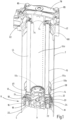
- the invention is explained using the example of a so-called in-tank filter device, which has a filter housing 2 in the form of a tubular body open at the lower end 4.
- the invention can be implemented with equal advantage in a filter device in which a filter housing is provided in the form of a filter bowl closed at the bottom.
- a housing receptacle 6 is fixed to the inside of the tubular body of the filter housing 2.
- the housing receptacle 6 is formed by a two-part annular body with a coaxial inner passage 8.
- the passage 8 continues with an upwardly projecting threaded socket 12, with whose external thread the internal thread of a threaded ring 26 of an element receptacle 14 for supporting a filter element 15 can be screwed.
- the element receptacle 14 can be releasably secured in the filter housing 2 via the internal thread.
- valve chambers 18 are arranged distributed around the outside of the central passage 8 for Bypass valves are formed, which have fluid passages from an upper annular surface 20 of the upper part 10 to fluid passages 22 on the lower part 16.
- the fluid passages 22 are normally closed by spring-loaded closing bodies 24.
- the Fig. 1 shows the filter element 15 in the installed functional position, in which the threaded ring 26, which projects coaxially downwards from the element holder 14, is screwed to the threaded socket 12 of the housing holder 6, whereby when the screw connection is tightened, the threaded ring 26 with its end 28 (see Fig. 2 ) rests against the circular surface 20 of the upper part 10.
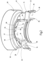
- the threaded ring 26 extends from the underside of a flat, annular cover surface 30 of the element holder 14, which extends in a radial plane and from whose outer circumference a bell-shaped jacket 32 extends in the direction of the threaded ring 26.
- the jacket 32 has wall openings 34 and delimits an annular space 36 between itself and the threaded ring 26.
- the filter element 15 has, in the usual way, an element material 44 in the form of a hollow cylinder extending between end caps 40 and 42. Of the end caps 40, 42, one, in Fig. 1 The lower end cap 40 is mounted on the element holder 14. To form the bearing, the element holder 14, see Fig. 2 to 4 , starting from the cover surface 30, has a coaxially upwardly projecting tubular body 48, the radially outer wall of which forms a bearing surface 46 in the form of a convexly curved annular surface.
- the end cap 40 has, starting from the radially inner edge of a flat bearing surface 50 for the front end of the element material 44, a tubular body 52 projecting upwardly and downwardly, the radially inner wall of which forms the second bearing surface 54 in the form of a concavely curved annular surface.
- FIG. 2 show the mounting state in which the end cap 40 with its tubular body 52 is plugged onto the tubular body 48 of the element holder 14, wherein the mounting is clipped to the adjacent bearing surfaces 46, 54 due to elastic resilience, in particular of the tubular body 48 standing freely on the cover surface 30.
- the respective bearing surface 46, 54 is part of a membrane-like shell 55a, 55b, of which at least one 55b has a passage 55c for liquid, which is fluid-conductingly connected to a cavity 55d in the filter element.
- the enclosure for the element material 44 resting on the contact surface 50 of the end cap 40 is formed radially inward by the tubular body 52 and radially outward by a lateral surface 56 which widens upwards in the radial direction to form a shell 58 which surrounds the end section of the element material 44 at a radial distance.
- the formed spherical bearing allows a deflection of the longitudinal axes of the element holder 14 relative to the filter element 15 from the aligned basic position, as shown in Fig. 1 and 2 is shown.
- the lower edge 61 of the tubular body 52 of the end cap 40 is at a distance from the cover surface 30 of the element holder 14.
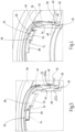
- the Figs. 3 and 4 In contrast, they show a deflected state, more precisely, the maximum possible deflection, in which the lower edge 60 of the annular body 52 rests against the cover surface 30 of the element holder 14, which forms a stop. This forms a blocking device that limits the maximum deflection.
- Fig. 2 to 4 show further details of a further blocking device, which is formed by configurations on the upper end edge 60 of the tubular body 48 of the element receptacle 14 and the upper end edge 62 of the tubular body 52 of the end cap 40.
- this blocking device has a locking block 64, which projects radially inward in the form of a rectangular short rib on the inside of the end edge 62 of the tubular body 52.
- a recess 66 is formed at the end edge 60, which extends into steps 68 and 70 (see in particular Figs. 3 and 4 ) extends over a respective circumferential section of the tubular body 48.
- the recess 66 forms an axial depression of the end edge 62, which corresponds to the axial thickness of the locking block 64 and is limited in the circumferential direction by a projection 72 slightly projecting from the step surface to a circumferential length which is only slightly greater than the circumferential length of the locking block 64, see Fig. 3 .
- the first step 68 is followed by the projection 72 by the second step 70, with which the end edge 62 is further recessed in the axial direction and which has a greater circumferential length than the first step 68.
- Fig. 2 and 3 show the basic position, in which the axis of filter element 15 with end cap 40 is aligned with the longitudinal axis of element holder 14.
- the locking body 64 of end cap 40 is located in the first step 68 of the clamping portion 66 of the tubular body 48 of element holder 14. Since the axial extent of the first step 68 corresponds to the thickness of locking block 64 measured in the axial direction, the spherical bearing is blocked against deflection.
- projection 72 impedes the sliding movement of locking block 64 in the circumferential direction, so that in this basic position, a rotary locking mechanism is formed between filter element 15 and element holder 14.
- the filter element 15, with the element holder 14 forming a rigid unit with it can therefore be conveniently and securely attached to the threaded ring 26 of the housing holder 6 and screwed tight with the formed rotary lock.
- the The rotational locking mechanism formed by the projection 72 can be overcome, so that the locking block 64 overruns the projection 72 and enters the free space formed by the second step 70 of the recess 66. Due to the greater axial depth of the step 70, the locking block 64 is no longer axially supported, so that the spherical bearing can be released and deflected within the limits formed by the first blocking device to compensate for misalignments.
- the other, upper end cap 42 is in the embodiment shown, see Fig. 1 , engages with an element receptacle formed by a socket 74 which engages with the central opening 76 of the end cap 42.
- a spherical bearing of the type shown on the lower end cap 40 could also be provided between the upper end cap 42 and the respective element receptacle.
- the socket 74 provided in the example shown is part of a housing cover 78 which is removably fastened by screw connections 85 to a filter head 80 which has an unfiltered material inlet 82 and, as is usual with in-tank filter devices, is attached to an opening in a tank wall (not shown).
Landscapes
- Chemical & Material Sciences (AREA)
- Chemical Kinetics & Catalysis (AREA)
- Filtration Of Liquid (AREA)
- Filtering Of Dispersed Particles In Gases (AREA)
- Lubrication Details And Ventilation Of Internal Combustion Engines (AREA)
Description
- Die Erfindung betrifft eine Filtervorrichtung mit einem Filtergehäuse und einem darin aufgenommenen Filterelement, dessen Elementmaterial sich zur Filtrierung einer Flüssigkeit zwischen zwei Endkappen erstreckt, von denen zumindest eine Endkappe an einer Elementaufnahme gelagert ist, wobei mittels einer mehr als einen Freiheitsgrad zur Verfügung stellenden Lagerung das Filterelement über seine eine Endkappe gelenkig an der Elementaufnahme gelagert ist.
- Filtervorrichtungen sind im Stand der Technik bekannt, vgl. beispielsweise
DE 101 42 774 A1 . Bei solchen Filtervorrichtungen, bei denen, wie bei dem erwähnten Dokument, Elementaufnahmen in formschlüssiger Verbindung mit Gehäuseteilen, wie Gehäusestutzen und/oder Stutzen am Gehäusedeckel sind, müssen bei der Fertigung von Filtergehäuse und Filtergehäuseteilen äußerst enge Toleranzen eingehalten werden, um sicherzustellen, dass die Achsen jeweiliger Elementaufnahmen der Endkappen mit den Achsen der gehäuseseitigen und/oder deckelseitigen Halteelemente, wie Stutzen, genau fluchten. Fertigungstoleranzen bei der Gehäuseherstellung, namentlich bei Gehäusekonstruktionen in mehrteiliger Bauweise mit mehreren aneinandergesetzten Gehäuseteilen, können zu Fluchtungsfehlern führen, durch die es zu Verspannungen im Filterelement kommt, die Fehlfunktionen oder gar Beschädigung zur Folge haben. Insbesondere Filtervorrichtungen mit langen Filterelementen sind von dieser Problematik betroffen, da hier bereits kleinste Winkelfehler und Positionsabweichungen großen Versatz am gegenüberliegenden Halteelement bedeuten. - Weitere Filtervorrichtungen gehen aus der
DE 10 2015 007 692 A1 , derWO 02/076570 A1 WO 2007/003517 A2 und derDE 10 2014 002 241 A1 hervor. - Im Hinblick auf diese Problematik stellt sich die Erfindung die Aufgabe, eine Filtervorrichtung der eingangs genannten Gattung zur Verfügung zu stellen, die rationell und kostengünstig herstellbar ist und sich zugleich durch ein sicheres Betriebsverhalten auszeichnet.
- Erfindungsgemäß ist diese Aufgabe durch eine Filtervorrichtung gelöst, die die Merkmale des Patentanspruchs 1 in seiner Gesamtheit aufweist.
- Gemäß dem kennzeichnenden Teil des Patentanspruchs 1 besteht eine wesentliche Besonderheit der Erfindung darin, dass die Lagerung eine konvex verlaufende Lagerfläche aufweist, die in einer konkav verlaufenden Lagerfläche geführt ist, und dass die jeweilige Lagerfläche Bestandteil einer Schale ist, von denen mindestens eine einen Durchlass für Flüssigkeit aufweist.
- Unter einer Schale im Sinne der Erfindung und im Sinne der Definition in der technischen Mechanik wird dabei ein flächiges Tragwerk verstanden, das doppelt räumlich gekrümmt ist, und dass insbesondere Belastungen sowohl senkrecht als auch in seiner Ebene aufnehmen kann. Schalen nutzen Ihre Tragfähigkeit durch das Verteilen von Lasten über Membrankräfte, die über die Dicke der Schale konstant sind, optimal aus, so dass die Schalen bei geringem Gewicht eine hohe Steifigkeit aufweisen.
- Ein besonderer Vorteil dieser Ausbildung der Lagerung über Schalen besteht darin, dass der Durchlass gegenüber der Rohseite der Filtervorrichtung auf der Außenseite des Filterelements abgedichtet ist.
- Es ist ferner vorgesehen, dass mittels einer mehr als einen Freiheitsgrad zur Verfügung stellenden Lagerung das Filterelement über seine eine Endkappe gelenkig an der Elementaufnahme gelagert ist. Dadurch steht eine Ausgleichsmöglichkeit für mögliche Versatzfehler zur Verfügung, so dass eine Reduzierung der engen einzuhaltenden Toleranzgrenzen für die Fertigung ermöglicht ist und somit Filtervorrichtungen auch mit lang bauenden Filterelementen oder mit zusammengesetzten Filtergehäusen betriebssicher und mit günstigen Herstellungskosten fertigbar sind.
- Mit Vorteil kann die Anordnung hierbei so getroffen sein, dass die Lagerung mindestens eine konvex verlaufende Lagerfläche aufweist, die in mindestens einer konkav verlaufenden Lagerfläche geführt ist. Dergestalt ist eine sphärische Lagerung ausgebildet, die eine Art Kugelgelenk zwischen der jeweiligen Endkappe und der Elementaufnahme bildet, so dass Fluchtungsfehler verspannungsfrei ausgleichbar sind.
- Die jeweils konvex verlaufende Lagerfläche kann Teil der Elementaufnahme sein, wobei die jeweils konkav verlaufende Lagerfläche Teil der einen Endkappe ist. Bei der kugeligen Form der Elementaufnahme ist dadurch das Filterelement mit seiner Lagerfläche einfach auf die Lagerfläche der Elementaufnahme aufschiebbar.
- Bei bevorzugten Ausführungsbeispielen sind die beiden in der Art einer Steck- oder Clipverbindung miteinander in Anlage befindlichen Lagerflächen sphärisch ausgebildet. Die miteinander korrespondierenden Wölbungen bilden dadurch eine axiale Sicherung des mit seiner Endkappe auf die Elementaufnahme aufgesteckten Filterelements.
- Bei vorteilhaften Ausführungsbeispielen ist die Elementaufnahme im Filtergehäuse vorzugsweise mittels einer Schraubverbindung festgelegt, wobei das Filterelement abschnittsweise mit seiner Längsachse aus der Längsachse der Elementaufnahme heraus in alle Richtungen um einen vorgebbaren Schwenkwinkel mittels der sphärischen Lagerung ausschwenkbar ist.
- Bei besonders vorteilhaften Ausführungsbeispielen ist eine Blockiereinrichtung vorgesehen, die den maximal möglichen Ausschwenkwinkel des Filterelements begrenzt, die zwischen der Endkappe des Filterelements und der Elementaufnahme wirkt und durch diese beiden gebildet ist. Die Begrenzung der maximalen Schrägstellung der Einheit aus Filterelement und Elementaufnahme erleichtert die Handhabung beim Einsetzen des Filterelements in das Filtergehäuse.
- Mit besonderem Vorteil kann die Anordnung so getroffen sein, dass eine weitere Blockiereinrichtung vorhanden ist, die beim Aufschrauben des Filterelements mit seiner Elementaufnahme auf eine im Inneren des Filtergehäuses angeordnete Gehäuseaufnahme die Schwenkbewegung aus der Grundstellung heraus unterbindet, bei der die Längsachsen von der einen Endkappe und der zugeordneten Elementaufnahme deckungsgleich miteinander sind, und dass bei festgelegter Elementaufnahme an der Gehäuseaufnahme und bei weiterer rotatorischer Drehbewegung der einen Endkappe gegenüber der Elementaufnahme, vorzugsweise in Aufschraubrichtung, die weitere Blockiereinrichtung die Schwenkbewegung aus der Grundstellung heraus freigibt. Mit im wirksamen Zustand befindlicher weiterer Blockiereinrichtung steht somit für den Einbauvorgang des Filterelements in das Filtergehäuse das Filterelement mit Elementaufnahme als starre Einheit mit fluchtenden Achsen zur Verfügung. Dies bildet eine besonders wirksame Montagehilfe beim Montagevorgang, bei dem die Elementaufnahme mit dem Gewinde der im Gehäuseinneren schlecht zugänglichen Gehäuseaufnahme in Eingriff gebracht werden muss. Da die Blockiereinrichtung im Zuge der Aufschraubdrehung des Filterelements deaktiviert wird, ist gleichzeitig sichergestellt, dass mit Abschluss des Einbau-Schraubvorgangs die sphärische Lagerung für den Ausgleich möglicher Fluchtungsfehler wirksam ist.
- Bei vorteilhaften Ausführungsbeispielen ist die weitere Endkappe des Filterelements an einer weiteren Gehäuseaufnahme im Inneren des Filtergehäuses festgelegt, wobei die weitere Gehäuseaufnahme vorzugsweise Bestandteil eines Gehäusedeckels ist, der auf einen Filterkopf als Teil des Filtergehäuses, insbesondere mittels mindestens einer Schraubverbindung, festgelegt ist. Die weitere Gehäuseaufnahme kann durch einen Stutzen des Gehäusedeckels gebildet sein, der in eine Öffnung der zugeordneten Endkappe des Filterelements eingreift. Der Stutzen kann einen Verschluss dieser Endkappe oder einen Fluidweg bilden, der vom Filterkopf ins Innere des Filterelements führt.
- Mit Vorteil kann die eine Gehäuseaufnahme mindestens ein federbelastetes Bypassventil aufweisen, das in seiner geöffneten Stellung, unter zumindest teilweiser Umgehung des Filterelements, den Fluidweg aus dem Inneren des Filtergehäuses an dessen Auslass freigibt. Der Fluidweg kann über eine von der einen Endkappe gebildete, an der Gehäuseaufnahme abgedichtete Kavität geführt sein, die ein Siebgewebe enthält, das bei geöffnetem Bypassventil durchströmt ist.
- Gemäß dem Patentanspruch 10 ist Gegenstand der Erfindung auch ein Filterelement, das insbesondere für eine Filtervorrichtung nach einem der Patentansprüche 1 bis 9 vorgesehen ist.
- Nachstehend ist die Erfindung anhand eines in der Zeichnung dargestellten Ausführungsbeispiels im Einzelnen erläutert. Es zeigen:
- Fig. 1
- eine mit zentraler, vertikaler Schnittebene aufgeschnittene perspektivische Schrägansicht des Ausführungsbeispiels der erfindungsgemäßen Filtervorrichtung;
- Fig. 2
- eine vergrößert gezeichnete, mit zentraler Vertikalebene aufgeschnittene perspektivische Schrägansicht der einen Endkappe und der dieser zugeordneten Elementaufnahme des Filterelements des Ausführungsbeispiels;
- Fig. 3
- eine gegenüber
Fig. 2 weiter vergrößerte perspektivische Schrägansicht, die den Bereich zweier Blockiereinrichtungen des Ausführungsbeispiels zeigt, die beide in der Blockierstellung dargestellt sind; und - Fig. 4
- eine der
Fig. 3 entsprechende Darstellung, wobei von den Blockiereinrichtungen eine in der Freigabestellung dargestellt ist. - Unter Bezug auf die Zeichnungen ist die Erfindung am Beispiel einer sog. In-Tank-Filtervorrichtung erläutert, die ein Filtergehäuse 2 in Form eines am unteren Ende 4 offenen Rohrkörpers aufweist. Die Erfindung ist gleichermaßen vorteilhaft bei einer Filtervorrichtung realisierbar, bei der ein Filtergehäuse in die Form eines bodenseitig geschlossenen Filtertopfes vorgesehen ist. In der Nähe des unteren Endes 4 ist eine Gehäuseaufnahme 6 an der Innenseite des Rohrkörpers des Filtergehäuses 2 festgelegt. Die Gehäuseaufnahme 6 ist durch einen zweiteiligen Ringkörper mit koaxialem innerem Durchgang 8 gebildet. Am Oberteil 10 setzt sich der Durchgang 8 mit einem nach oben vorstehenden Gewindestutzen 12 fort, mit dessen Außengewinde das Innengewinde eines Gewinderinges 26 einer Elementaufnahme 14 für die Lagerung eines Filterelements 15 verschraubbar ist. Über das Innengewinde ist die Elementaufnahme 14 lösbar im Filtergehäuse 2 festlegbar. Im Unterteil 16 der Gehäuseaufnahme 6 sind um die Außenseite des zentralen Durchgangs 8 verteilt angeordnete Ventilkammern 18 für Bypassventile gebildet, die Fluiddurchgänge von einer oberen Kreisringfläche 20 des Oberteils 10 zu Fluiddurchgängen 22 am Unterteil 16 aufweisen. Die Fluiddurchgänge 22 sind durch federbelastete Schließkörper 24 normalerweise geschlossen.
- Die
Fig. 1 zeigt das Filterelement 15 in der eingebauten Funktionsposition, bei der der von der Elementaufnahme 14 koaxial nach unten vorstehender Gewindering 26 mit dem Gewindestutzen 12 der Gehäuseaufnahme 6 verschraubt ist, wobei bei festgezogener Verschraubung der Gewindering 26 mit seinem Ende 28 (s.Fig. 2 ) an der Kreisringfläche 20 des Oberteils 10 anliegt. Wie am deutlichsten derFig. 2 entnehmbar ist, erstreckt sich der Gewindering 26 von der Unterseite einer in einer Radialebene verlaufenden, ebenen, ringförmigen Deckfläche 30 der Elementaufnahme 14, von deren Außenumfang sich ein glockenartiger Mantel 32 in Richtung des Gewinderings 26 erstreckt. Der Mantel 32 weist Wanddurchbrüche 34 auf und begrenzt zwischen sich und dem Gewindering 26 einen Ringraum 36. Bei der verschraubten, inFig. 1 gezeigten Funktionsposition steht der Mantel 32 mit seinem unteren Ringrand 38, ebenso wie das Ende 28 des Gewinderings 26, an der Kreisringfläche 20 des Oberteils 10 der Gehäuseaufnahme 6 an. - Das Filterelement 15 weist in üblicher Weise ein zwischen Endkappen 40 und 42 verlaufendes Elementmaterial 44 in Form eines Hohlzylinders auf. Von den Endkappen 40, 42 ist die eine, in
Fig. 1 untenliegende Endkappe 40 an der Elementaufnahme 14 gelagert. Zur Bildung der Lagerung weist die Elementaufnahme 14, s.Fig. 2 bis 4 , von der Deckfläche 30 ausgehend, einen koaxial nach oben vorstehenden Rohrkörper 48 auf, dessen radial außenliegende Wand eine Lagerfläche 46 in Form einer konvex gewölbten Ringfläche bildet. Die Endkappe 40 weist, ausgehend vom radial inneren Rand einer ebenen Anlagefläche 50 für das stirnseitige Ende des Elementmaterials 44 einen nach oben und nach unten vorstehenden Rohrkörper 52 auf, dessen radial innenliegende Wand die zweite Lagerfläche 54 in Form einer konkav gewölbten Ringfläche bildet. - Die Figuren, siehe insbesondere
Fig. 2 , zeigen den Lagerungszustand, bei dem die Endkappe 40 mit ihrem Rohrkörper 52 auf den Rohrkörper 48 der Elementaufnahme 14 aufgesteckt ist, wobei die Lagerung mit den aneinanderliegenden Lagerflächen 46, 54 aufgrund elastischer Nachgiebigkeit insbesondere des auf der Deckfläche 30 freistehenden Rohrkörpers 48 verclipst ist. Durch die Anlage der konvexen Lagerfläche 46 an der konkaven Lagerfläche 54 ist eine sphärische Lagerung in der Art eines Kugelgelenks zwischen Endkappe 40 und Elementaufnahme 14 gebildet. Die jeweilige Lagerfläche 46, 54 ist Bestandteil einer membranartigen Schale 55a, 55b, von denen mindestens eine 55b einen Durchlass 55c für Flüssigkeit aufweist, der mit einem Hohlraum 55d im Filterelement fluidführend verbunden ist. Die Einfassung für das auf der Anlagefläche 50 der Endkappe 40 anstehende Elementmaterial 44 ist radial innen durch den Rohrkörper 52 und radial außen durch eine Mantelfläche 56 gebildet, die sich nach oben hin in Radialrichtung zu einer Schale 58 erweitert, die den Endabschnitt des Elementmaterials 44 in einem radialen Abstand umgibt. - Die gebildete sphärische Lagerung erlaubt eine Auslenkung der Längsachsen von Elementaufnahme 14 relativ zum Filterelement 15 aus der fluchtenden Grundstellung heraus, wie sie in
Fig. 1 und2 gezeigt ist. Bei dieser fluchtenden Stellung befindet sich der untere Rand 61 des Rohrkörpers 52 der Endkappe 40 in einem Abstand von der Deckfläche 30 der Elementaufnahme 14. DieFig. 3 und 4 zeigen demgegenüber einen ausgelenkten Zustand, genauer gesagt, die maximal mögliche Auslenkung, bei der der untere Rand 60 des Ringkörpers 52 an der einen Anschlag bildenden Deckfläche 30 der Elementaufnahme 14 anliegt. Dadurch ist eine die maximale Auslenkung begrenzende Blockiereinrichtung gebildet. - Die
Fig. 2 bis 4 zeigen nähere Einzelheiten einer weiteren Blockiereinrichtung, die durch Ausgestaltungen am oberen Endrand 60 des Rohrkörpers 48 der Elementaufnahme 14 und des oberen Endrandes 62 des Rohrkörpers 52 der Endkappe 40 gebildet ist. Wie gezeigt, weist diese Blockiereinrichtung einen Sperrblock 64 auf, der in Form einer rechteckförmigen kurzen Rippe an der Innenseite des Endrandes 62 des Rohrkörpers 52 radial nach innen vorsteht. An dem anderen, innenliegenden Rohrkörper 48 ist am Endrand 60 eine Aussparung 66 gebildet, die sich in Stufen 68 und 70 (siehe insbesondereFig. 3 und 4 ) über jeweils einen Umfangsabschnitt des Rohrkörpers 48 erstreckt. Mit der ersten Stufe 68 bildet die Aussparung 66 eine axiale Vertiefung des Endrandes 62, die der axialen Dicke des Sperrblockes 64 entspricht und ist in Umfangsrichtung durch einen aus der Stufenfläche geringfügig vorstehenden Vorsprung 72 auf eine Umfangslänge begrenzt, die nur geringfügig größer ist als die in Umfangsrichtung gemessene Länge des Sperrblockes 64, sieheFig. 3 . An die erste Stufe 68 schließt sich anschließend an den Vorsprung 72 die zweite Stufe 70 an, mit der der Endrand 62 in Axialrichtung weiter vertieft ist und die eine größere Umfangslänge besitzt als die erste Stufe 68. - Bei dieser Anordnung ist die Funktion dieser weiteren Blockiereinrichtung wie folgt: Die
Fig. 2 und3 zeigen die Grundstellung, bei der die Achse von Filterelement 15 mit Endkappe 40 in Fluchtung mit der Längsachse der Elementaufnahme 14 ist. Der Sperrkörper 64 der Endkappe 40 befindet sich in der ersten Stufe 68 der Ausspannung 66 des Rohrkörpers 48 der Elementaufnahme 14. Da die axiale Erstreckung der ersten Stufe 68 der in Axialrichtung gemessenen Dicke des Sperrblockes 64 entspricht, ist die sphärische Lagerung gegen Auslenkung blockiert. Gleichzeitig behindert der Vorsprung 72 die Verschiebebewegung des Sperrblockes 64 in Umfangsrichtung, so dass bei dieser Grundstellung eine Drehverrastung zwischen Filterelement 15 und Elementaufnahme 14 gebildet ist. In der Grundstellung ist daher beim Montagevorgang für den Einbau des Filterelements 15 in das Filtergehäuse 2 das Filterelement 15 mit der mit ihm eine starre Einheit bildenden Elementaufnahme 14 bequem und sicher an den Gewindering 26 der Gehäuseaufnahme 6 ansetzbar und mit der gebildeten Drehverrastung festschraubbar. Bei gebildeter Verschraubung ist durch Weiterdrehen die durch den Vorsprung 72 gebildete Drehverrastung überwindbar, so dass der Sperrblock 64 den Vorsprung 72 überläuft und in den durch die zweite Stufe 70 der Aussparung 66 gebildeten Freiraum gelangt. Aufgrund der größeren axialen Tiefe der Stufe 70 ist der Sperrblock 64 nicht mehr axial abgestützt, so dass die sphärische Lagerung freigeben und in den durch die erste Blockiereinrichtung gebildeten Grenzen für den Ausgleich von Fluchtungsfehlern auslenkbar ist. - Die andere, obere Endkappe 42 ist beim gezeigten Ausführungsbeispiel, siehe
Fig. 1 , mit einer Elementaufnahme in Eingriff, die durch einen Stutzen 74 gebildet ist, der mit der zentralen Öffnung 76 der Endkappe 42 in Eingriff ist. Anstelle dieses formschlüssigen Eingriffes könnte auch zwischen oberer Endkappe 42 und betreffender Elementaufnahme eine sphärische Lagerung der an der unteren Endkappe 40 gezeigten Art vorgesehen sein. Der beim gezeigten Beispiel vorgesehene Stutzen 74 ist Bestandteil eines Gehäusedeckels 78, der durch Schraubverbindungen 85 abnehmbar an einem Filterkopf 80 befestigt ist, der einen Unfiltrateingang 82 aufweist und, wie bei In-Tank-Filtervorrichtungen üblich, an einer Öffnung in einer nicht gezeigten Tankwand angebracht ist. Bei der inFig. 1 gezeigten Funktionsposition sind das Ende 28 des Gewinderinges 26 und der Endrand 38 der Elementaufnahme 14 in dichter Anlage an der Kreisringfläche 20 der Gehäuseaufnahme 6. Für den Zugang von Unfiltrat zu den Bypassventilen im Unterteil 16 der Gehäuseaufnahme 6 bildet der innerhalb des Mantels 32 befindliche Ringraum 36 einen Einströmraum, in den Unfiltrat über die Wanddurchbrüche 34 gelangt. In der Kreisringfläche 20, die den Boden dieses Ringraumes 36 bildet, sind Öffnungen 84 vorgesehen, die vom Schließkörper 24 des jeweiligen Bypassventils normalerweise geschlossen sind. An den Wanddurchbrüchen 34 des Mantels 32 können eingespritzte Siebgitter vorgesehen sein, die bei druckbetätigter Öffnung eines Bypassventils eine Filtrierung des Unfiltratstroms bewirken. Bei einer nicht dargestellten Ausführungsform besteht auch die Möglichkeit die vorgestellte sphärische Lagerung vom unteren an das obere Elementende zu verlegen, oder an beiden Elementenden eine solche Lagerung vorzusehen.
Claims (10)
- Filtervorrichtung mit einem Filtergehäuse (2) und einem darin aufgenommenen Filterelement (15), dessen Elementmaterial (44) sich zur Filtrierung einer Flüssigkeit zwischen zwei Endkappen (40, 42) erstreckt, von denen zumindest eine Endkappe (40) an einer Elementaufnahme (14) gelagert ist, wobei mittels einer mehr als einen Freiheitsgrad zur Verfügung stellenden Lagerung (46, 54) das Filterelement (15) über seine eine Endkappe (40) gelenkig an der Elementaufnahme (14) gelagert ist, dadurch gekennzeichnet, dass die Lagerung eine konvex verlaufende Lagerfläche (46) aufweist, die in einer konkav verlaufenden Lagerfläche (54) geführt ist, und dass die jeweilige Lagerfläche (46, 54) Bestandteil einer Schale (55a, 55b) ist, von denen mindestens eine (55b) einen Durchlass (55c) für Flüssigkeit aufweist.
- Filtervorrichtung nach Anspruch 1, dadurch gekennzeichnet, dass die jeweils konvex verlaufende Lagerfläche (46) Teil der Elementaufnahme (14) ist und die jeweils konkav verlaufende Lagerfläche (54) Teil der einen Endkappe (40) ist.
- Filtervorrichtung nach Anspruch 1 oder 2, dadurch gekennzeichnet, dass die beiden in der Art einer Steck- oder Clipverbindung miteinander in Anlage befindlichen Lagerflächen (46, 54) sphärisch ausgebildet sind.
- Filtervorrichtung nach einem der vorstehenden Ansprüche, dadurch gekennzeichnet, dass die Elementaufnahme (14) im Filtergehäuse (2) vorzugsweise mittels einer Schraubverbindung (12, 26) festgelegt ist.
- Filtervorrichtung nach Anspruch 3 oder 4, dadurch gekennzeichnet, dass das Filterelement (15) abschnittsweise mit seiner Längsachse aus der Längsachse der Elementaufnahme (14) heraus in alle Richtungen um einen vorgebbaren Schwenkwinkel mittels der sphärischen Lagerung (46, 54) ausschwenkbar ist.
- Filtervorrichtung nach einem der vorstehenden Ansprüche, dadurch gekennzeichnet, dass eine Blockiereinrichtung (30, 61) vorgesehen ist, die den maximal möglichen Auslenkwinkel des Filterelements (15) begrenzt, die zwischen der Endkappe (40) des Filterelements (15) und der Elementaufnahme (14) wirkt und durch diese beiden gebildet ist.
- Filtervorrichtung nach einem der vorstehenden Ansprüche, dadurch gekennzeichnet, dass eine weitere Blockiereinrichtung (64, 66, 68, 70) vorhanden ist, die beim Aufschrauben des Filterelements (15) mit seiner Elementaufnahme (14) auf eine im Innern des Filtergehäuses (2) angeordnete Gehäuseaufnahme (6) die Schwenkbewegung aus einer Grundstellung heraus unterbindet, bei der die Längsachsen von der einen Endkappe (40) und der zugeordneten Elementaufnahme (14) deckungsgleich miteinander sind, und dass bei festgelegter Elementaufnahme (14) an der Gehäuseaufnahme (6) und bei weiterer rotatorischer Drehbewegung der einen Endkappe (40) gegenüber der Elementaufnahme (14), vorzugsweise in Aufschraubrichtung, die weitere Blockiereinrichtung (64, 66, 68, 70) die Schwenkbewegung aus der Grundstellung heraus freigibt.
- Filtervorrichtung nach einem der vorstehenden Ansprüche, dadurch gekennzeichnet, dass die weitere Endkappe (42) des Filterelements (15) an einer weiteren Gehäuseaufnahme (74) im Inneren des Filtergehäuses (2) festgelegt ist und dass die weitere Gehäuseaufnahme (74) vorzugsweise Bestandteil eines Gehäusedeckels (78) ist, der auf einem Filterkopf (80) als Teil des Filtergehäuses (2), insbesondere mittels mindestens einer Schraubverbindung (84), festgelegt ist.
- Filtervorrichtung nach einem der vorstehenden Ansprüche, dadurch gekennzeichnet, dass die eine Gehäuseaufnahme (6) mindestens ein federbelastetes Bypassventil (24) aufweist, das in seiner geöffneten Stellung, unter zumindest teilweiser Umgehung des Filterelements (15), den Fluidweg aus dem Inneren des Filtergehäuses (2) an dessen Auslass (4) freigibt.
- Filterelement (15), dessen Elementmaterial (44) sich zur Filtrierung einer Flüssigkeit zwischen zwei Endkappen (40, 42) erstreckt, von denen zumindest eine Endkappe (40) an einer Elementaufnahme (14) gelagert ist, wobei mittels einer mehr als einen Freiheitsgrad zur Verfügung stellenden Lagerung (46, 54) das Filterelement (15) über seine eine Endkappe (40) gelenkig an der Elementaufnahme (14) gelagert ist, dadurch gekennzeichnet, dass die Lagerung eine konvex verlaufende Lagerfläche (46) aufweist, die in einer konkav verlaufenden Lagerfläche (54) geführt ist, und dass die jeweilige Lagerfläche (46, 54) Bestandteil einer Schale (55a, 55b) ist, von denen mindestens eine (55b) einen Durchlass (55c) für Flüssigkeit aufweist.
Applications Claiming Priority (2)
| Application Number | Priority Date | Filing Date | Title |
|---|---|---|---|
| DE102018009187.3A DE102018009187A1 (de) | 2018-11-23 | 2018-11-23 | Filtervorrichtung |
| PCT/EP2019/081063 WO2020104260A1 (de) | 2018-11-23 | 2019-11-12 | Filtervorrichtung |
Publications (3)
| Publication Number | Publication Date |
|---|---|
| EP3849687A1 EP3849687A1 (de) | 2021-07-21 |
| EP3849687C0 EP3849687C0 (de) | 2025-06-04 |
| EP3849687B1 true EP3849687B1 (de) | 2025-06-04 |
Family
ID=68581797
Family Applications (1)
| Application Number | Title | Priority Date | Filing Date |
|---|---|---|---|
| EP19804698.9A Active EP3849687B1 (de) | 2018-11-23 | 2019-11-12 | Filtervorrichtung |
Country Status (5)
| Country | Link |
|---|---|
| US (1) | US12109514B2 (de) |
| EP (1) | EP3849687B1 (de) |
| JP (1) | JP7519355B2 (de) |
| DE (1) | DE102018009187A1 (de) |
| WO (1) | WO2020104260A1 (de) |
Families Citing this family (9)
| Publication number | Priority date | Publication date | Assignee | Title |
|---|---|---|---|---|
| DE102019006455A1 (de) * | 2019-09-09 | 2021-03-11 | Hydac Filtertechnik Gmbh | Filtervorrichtung |
| DE102021000716A1 (de) | 2021-02-12 | 2022-08-18 | H Y D A C Filtertechnik GmbH | Filtervorrichtung und Filterelement |
| DE102021000750A1 (de) | 2021-02-13 | 2022-08-18 | H Y D A C Filtertechnik GmbH | Filtervorrichtung und Filterelement |
| DE102022002290A1 (de) | 2022-06-24 | 2024-01-04 | Hydac Filtertechnik Gmbh | Filterelement |
| US20240050878A1 (en) * | 2022-08-15 | 2024-02-15 | Hydac Filtertechnik Gmbh | Filter device and filter element |
| US12589341B2 (en) | 2022-08-15 | 2026-03-31 | Hydac Filtertechnik Gmbh | Filter device and filter element |
| DE102023002529A1 (de) | 2023-06-22 | 2024-12-24 | Hydac Filtertechnik Gmbh | Filterelement |
| DE102023002530A1 (de) | 2023-06-22 | 2024-12-24 | Hydac Filtertechnik Gmbh | Filtervorrichtung |
| DE102023003101A1 (de) * | 2023-07-18 | 2025-01-23 | Hydac Filtertechnik Gmbh | Filtervorrichtung und Filterelement |
Family Cites Families (15)
| Publication number | Priority date | Publication date | Assignee | Title |
|---|---|---|---|---|
| DE10038531A1 (de) * | 2000-08-08 | 2002-02-21 | Mann & Hummel Filter | Flüssigkeitsfilter |
| FR2822394B1 (fr) * | 2001-03-23 | 2003-05-09 | Fleetguard | Ensemble de filtrage pourvu de moyens facilitant le remplacement de la cartouche de filtration |
| DE10142774A1 (de) | 2001-08-31 | 2003-03-27 | Hydac Filtertechnik Gmbh | Filtervorrichtung |
| WO2003082435A1 (en) * | 2002-03-28 | 2003-10-09 | Mykrolis Corporation | Filter cartridge construction |
| DE202005010445U1 (de) * | 2005-06-30 | 2006-11-16 | Mann + Hummel Gmbh | Filteranordnung für Flüssigkeiten |
| EP2059320B1 (de) * | 2006-09-05 | 2014-09-24 | Pall Corporation | Filterlemente und anordnungen |
| WO2009058520A2 (en) * | 2007-10-29 | 2009-05-07 | 3M Innovative Properties Company | Latch reset filter unit |
| DE202007017614U1 (de) * | 2007-12-14 | 2009-04-30 | Mann + Hummel Gmbh | Ölfilter |
| DE102009013070A1 (de) * | 2009-03-13 | 2010-09-23 | Hydac Filtertechnik Gmbh | Filtervorrichtung, insbesondere Rücklauf-Saugfilter, sowie Filterelement für den Einsatz bei einer solchen Filtervorrichtung |
| DE102009049868A1 (de) * | 2009-10-20 | 2011-04-21 | Mahle International Gmbh | Filtereinrichtung |
| DE102013202449A1 (de) * | 2013-02-14 | 2014-08-14 | Mahle International Gmbh | Filtereinrichtung |
| DE102014002241B4 (de) * | 2014-02-20 | 2016-10-06 | Mann + Hummel Gmbh | Filtersystem und Filterelement mit Kupplungsvorrichtung und Verriegelungsvorrichtung, sowie Verwendung des Filtersystems |
| DE102014211799A1 (de) * | 2014-05-05 | 2015-11-05 | Volkswagen Aktiengesellschaft | Filterkartusche für einen Druckfilter und Filteranordnung für ein Kraftfahrzeug |
| DE102015007692A1 (de) * | 2015-06-09 | 2016-12-15 | Rt-Filtertechnik Gmbh | Filterelement |
| EP3249184B1 (de) * | 2016-05-23 | 2018-07-18 | Hengst SE | Ölfilterkartusche und gehäuse für eine ölfilterkartusche |
-
2018
- 2018-11-23 DE DE102018009187.3A patent/DE102018009187A1/de not_active Withdrawn
-
2019
- 2019-11-12 JP JP2021529040A patent/JP7519355B2/ja active Active
- 2019-11-12 US US17/290,805 patent/US12109514B2/en active Active
- 2019-11-12 EP EP19804698.9A patent/EP3849687B1/de active Active
- 2019-11-12 WO PCT/EP2019/081063 patent/WO2020104260A1/de not_active Ceased
Also Published As
| Publication number | Publication date |
|---|---|
| EP3849687C0 (de) | 2025-06-04 |
| US20210370202A1 (en) | 2021-12-02 |
| DE102018009187A1 (de) | 2020-05-28 |
| JP7519355B2 (ja) | 2024-07-19 |
| JP2022511750A (ja) | 2022-02-01 |
| WO2020104260A1 (de) | 2020-05-28 |
| EP3849687A1 (de) | 2021-07-21 |
| US12109514B2 (en) | 2024-10-08 |
Similar Documents
| Publication | Publication Date | Title |
|---|---|---|
| EP3849687A1 (de) | Filtervorrichtung | |
| EP3329979B1 (de) | Filtergehäuse und filtereinsatz | |
| EP3999206B1 (de) | Filtervorrichtung | |
| EP2720771B1 (de) | Flüssigkeitsfilter mit einem exzentrischen flüssigkeitsablasskanal | |
| DE29613703U1 (de) | Flüssigkeitsfilter, insbesondere für Öl oder Kraftstoff einer Brennkraftmaschine, und dazu passender maschinenseitiger Filteranschlußflansch | |
| EP2489538B1 (de) | Füllstutzen für den Treibstofftank eines Kraftfahrzeuges mit selektiver Öffnung | |
| DE102015007692A1 (de) | Filterelement | |
| DE102015007691A1 (de) | Filtervorrichtung | |
| EP2054132B1 (de) | Ölfilteranordnung | |
| EP3958996A1 (de) | Filtervorrichtung | |
| EP1132247B1 (de) | Verschlussanordnung für einen Kraftstofftank eines Kraftfahrzeuges | |
| DE69904275T2 (de) | Rückschlagventil für kraftstofftank | |
| EP3953624B1 (de) | Explosionsschutzventil zur entkopplung von anlagen- oder werkteilen mit einem dichtungsring | |
| EP4043082B1 (de) | Filtervorrichtung und filterelement | |
| EP4171781B1 (de) | Filtereinrichtung mit einem filterelement | |
| DE29922324U1 (de) | Flüssigkeitsfilter | |
| DE102018108976A1 (de) | Druckbegrenzungsventil | |
| EP1731210B1 (de) | Filtereinrichtung mit einem Filterelement | |
| EP4043083B1 (de) | Filtervorrichtung und filterelement | |
| DE20100363U1 (de) | Freistrahlzentrifuge | |
| EP3953592B1 (de) | Sicherungsring, anordnung und verfahren zur montage des sicherungsrings | |
| DE202006006249U1 (de) | Flüssigkeitsbehälter | |
| EP3342966B1 (de) | Scharnier zur verschwenkung einer tür | |
| DE20201418U1 (de) | Vorrichtung zum Abtrennen von Verunreinigungen aus dem Schmieröl einer Brennkraftmaschine | |
| DE102023002530A1 (de) | Filtervorrichtung |
Legal Events
| Date | Code | Title | Description |
|---|---|---|---|
| STAA | Information on the status of an ep patent application or granted ep patent |
Free format text: STATUS: UNKNOWN |
|
| STAA | Information on the status of an ep patent application or granted ep patent |
Free format text: STATUS: THE INTERNATIONAL PUBLICATION HAS BEEN MADE |
|
| PUAI | Public reference made under article 153(3) epc to a published international application that has entered the european phase |
Free format text: ORIGINAL CODE: 0009012 |
|
| STAA | Information on the status of an ep patent application or granted ep patent |
Free format text: STATUS: REQUEST FOR EXAMINATION WAS MADE |
|
| 17P | Request for examination filed |
Effective date: 20210415 |
|
| AK | Designated contracting states |
Kind code of ref document: A1 Designated state(s): AL AT BE BG CH CY CZ DE DK EE ES FI FR GB GR HR HU IE IS IT LI LT LU LV MC MK MT NL NO PL PT RO RS SE SI SK SM TR |
|
| RAP3 | Party data changed (applicant data changed or rights of an application transferred) |
Owner name: HYDAC FILTERTECHNIK GMBH |
|
| DAV | Request for validation of the european patent (deleted) | ||
| DAX | Request for extension of the european patent (deleted) | ||
| STAA | Information on the status of an ep patent application or granted ep patent |
Free format text: STATUS: EXAMINATION IS IN PROGRESS |
|
| 17Q | First examination report despatched |
Effective date: 20220907 |
|
| GRAP | Despatch of communication of intention to grant a patent |
Free format text: ORIGINAL CODE: EPIDOSNIGR1 |
|
| STAA | Information on the status of an ep patent application or granted ep patent |
Free format text: STATUS: GRANT OF PATENT IS INTENDED |
|
| INTG | Intention to grant announced |
Effective date: 20250321 |
|
| GRAS | Grant fee paid |
Free format text: ORIGINAL CODE: EPIDOSNIGR3 |
|
| GRAA | (expected) grant |
Free format text: ORIGINAL CODE: 0009210 |
|
| STAA | Information on the status of an ep patent application or granted ep patent |
Free format text: STATUS: THE PATENT HAS BEEN GRANTED |
|
| AK | Designated contracting states |
Kind code of ref document: B1 Designated state(s): AL AT BE BG CH CY CZ DE DK EE ES FI FR GB GR HR HU IE IS IT LI LT LU LV MC MK MT NL NO PL PT RO RS SE SI SK SM TR |
|
| REG | Reference to a national code |
Ref country code: GB Ref legal event code: FG4D Free format text: NOT ENGLISH |
|
| REG | Reference to a national code |
Ref country code: CH Ref legal event code: EP |
|
| REG | Reference to a national code |
Ref country code: IE Ref legal event code: FG4D Free format text: LANGUAGE OF EP DOCUMENT: GERMAN |
|
| U01 | Request for unitary effect filed |
Effective date: 20250604 |
|
| U07 | Unitary effect registered |
Designated state(s): AT BE BG DE DK EE FI FR IT LT LU LV MT NL PT RO SE SI Effective date: 20250611 |
|
| PG25 | Lapsed in a contracting state [announced via postgrant information from national office to epo] |
Ref country code: ES Free format text: LAPSE BECAUSE OF FAILURE TO SUBMIT A TRANSLATION OF THE DESCRIPTION OR TO PAY THE FEE WITHIN THE PRESCRIBED TIME-LIMIT Effective date: 20250604 |
|
| PG25 | Lapsed in a contracting state [announced via postgrant information from national office to epo] |
Ref country code: NO Free format text: LAPSE BECAUSE OF FAILURE TO SUBMIT A TRANSLATION OF THE DESCRIPTION OR TO PAY THE FEE WITHIN THE PRESCRIBED TIME-LIMIT Effective date: 20250904 Ref country code: GR Free format text: LAPSE BECAUSE OF FAILURE TO SUBMIT A TRANSLATION OF THE DESCRIPTION OR TO PAY THE FEE WITHIN THE PRESCRIBED TIME-LIMIT Effective date: 20250905 |
|
| PG25 | Lapsed in a contracting state [announced via postgrant information from national office to epo] |
Ref country code: PL Free format text: LAPSE BECAUSE OF FAILURE TO SUBMIT A TRANSLATION OF THE DESCRIPTION OR TO PAY THE FEE WITHIN THE PRESCRIBED TIME-LIMIT Effective date: 20250604 |
|
| PG25 | Lapsed in a contracting state [announced via postgrant information from national office to epo] |
Ref country code: HR Free format text: LAPSE BECAUSE OF FAILURE TO SUBMIT A TRANSLATION OF THE DESCRIPTION OR TO PAY THE FEE WITHIN THE PRESCRIBED TIME-LIMIT Effective date: 20250604 |
|
| PG25 | Lapsed in a contracting state [announced via postgrant information from national office to epo] |
Ref country code: RS Free format text: LAPSE BECAUSE OF FAILURE TO SUBMIT A TRANSLATION OF THE DESCRIPTION OR TO PAY THE FEE WITHIN THE PRESCRIBED TIME-LIMIT Effective date: 20250904 |
|
| REG | Reference to a national code |
Ref country code: CH Ref legal event code: U11 Free format text: ST27 STATUS EVENT CODE: U-0-0-U10-U11 (AS PROVIDED BY THE NATIONAL OFFICE) Effective date: 20251201 |
|
| U20 | Renewal fee for the european patent with unitary effect paid |
Year of fee payment: 7 Effective date: 20251201 |
|
| PG25 | Lapsed in a contracting state [announced via postgrant information from national office to epo] |
Ref country code: IS Free format text: LAPSE BECAUSE OF FAILURE TO SUBMIT A TRANSLATION OF THE DESCRIPTION OR TO PAY THE FEE WITHIN THE PRESCRIBED TIME-LIMIT Effective date: 20251004 |
|
| PGFP | Annual fee paid to national office [announced via postgrant information from national office to epo] |
Ref country code: GB Payment date: 20251001 Year of fee payment: 7 |
|
| PG25 | Lapsed in a contracting state [announced via postgrant information from national office to epo] |
Ref country code: SM Free format text: LAPSE BECAUSE OF FAILURE TO SUBMIT A TRANSLATION OF THE DESCRIPTION OR TO PAY THE FEE WITHIN THE PRESCRIBED TIME-LIMIT Effective date: 20250604 |
|
| PGFP | Annual fee paid to national office [announced via postgrant information from national office to epo] |
Ref country code: CH Payment date: 20251201 Year of fee payment: 7 |
|
| PG25 | Lapsed in a contracting state [announced via postgrant information from national office to epo] |
Ref country code: CZ Free format text: LAPSE BECAUSE OF FAILURE TO SUBMIT A TRANSLATION OF THE DESCRIPTION OR TO PAY THE FEE WITHIN THE PRESCRIBED TIME-LIMIT Effective date: 20250604 |
|
| PG25 | Lapsed in a contracting state [announced via postgrant information from national office to epo] |
Ref country code: SK Free format text: LAPSE BECAUSE OF FAILURE TO SUBMIT A TRANSLATION OF THE DESCRIPTION OR TO PAY THE FEE WITHIN THE PRESCRIBED TIME-LIMIT Effective date: 20250604 |
|
| PLBE | No opposition filed within time limit |
Free format text: ORIGINAL CODE: 0009261 |
|
| STAA | Information on the status of an ep patent application or granted ep patent |
Free format text: STATUS: NO OPPOSITION FILED WITHIN TIME LIMIT |
|
| REG | Reference to a national code |
Ref country code: CH Ref legal event code: L10 Free format text: ST27 STATUS EVENT CODE: U-0-0-L10-L00 (AS PROVIDED BY THE NATIONAL OFFICE) Effective date: 20260416 |
|
| 26N | No opposition filed |
Effective date: 20260305 |
|
| PG25 | Lapsed in a contracting state [announced via postgrant information from national office to epo] |
Ref country code: MC Free format text: LAPSE BECAUSE OF FAILURE TO SUBMIT A TRANSLATION OF THE DESCRIPTION OR TO PAY THE FEE WITHIN THE PRESCRIBED TIME-LIMIT Effective date: 20250604 |