EP3849832B1 - Transportkühlvorrichtung, leistungsverwaltungssystem und leistungsverwaltungsverfahren - Google Patents
Transportkühlvorrichtung, leistungsverwaltungssystem und leistungsverwaltungsverfahren Download PDFInfo
- Publication number
- EP3849832B1 EP3849832B1 EP19773270.4A EP19773270A EP3849832B1 EP 3849832 B1 EP3849832 B1 EP 3849832B1 EP 19773270 A EP19773270 A EP 19773270A EP 3849832 B1 EP3849832 B1 EP 3849832B1
- Authority
- EP
- European Patent Office
- Prior art keywords
- power
- generator
- battery
- compressor
- control module
- Prior art date
- Legal status (The legal status is an assumption and is not a legal conclusion. Google has not performed a legal analysis and makes no representation as to the accuracy of the status listed.)
- Active
Links
Images
Classifications
-
- B—PERFORMING OPERATIONS; TRANSPORTING
- B60—VEHICLES IN GENERAL
- B60H—ARRANGEMENTS OF HEATING, COOLING, VENTILATING OR OTHER AIR-TREATING DEVICES SPECIALLY ADAPTED FOR PASSENGER OR GOODS SPACES OF VEHICLES
- B60H1/00—Heating, cooling or ventilating devices
- B60H1/32—Cooling devices
- B60H1/3204—Cooling devices using compression
- B60H1/3232—Cooling devices using compression particularly adapted for load transporting vehicles
-
- B—PERFORMING OPERATIONS; TRANSPORTING
- B60—VEHICLES IN GENERAL
- B60H—ARRANGEMENTS OF HEATING, COOLING, VENTILATING OR OTHER AIR-TREATING DEVICES SPECIALLY ADAPTED FOR PASSENGER OR GOODS SPACES OF VEHICLES
- B60H1/00—Heating, cooling or ventilating devices
- B60H1/00357—Air-conditioning arrangements specially adapted for particular vehicles
- B60H1/00364—Air-conditioning arrangements specially adapted for particular vehicles for caravans or trailers
-
- B—PERFORMING OPERATIONS; TRANSPORTING
- B60—VEHICLES IN GENERAL
- B60H—ARRANGEMENTS OF HEATING, COOLING, VENTILATING OR OTHER AIR-TREATING DEVICES SPECIALLY ADAPTED FOR PASSENGER OR GOODS SPACES OF VEHICLES
- B60H1/00—Heating, cooling or ventilating devices
- B60H1/00642—Control systems or circuits; Control members or indication devices for heating, cooling or ventilating devices
- B60H1/00735—Control systems or circuits characterised by their input, i.e. by the detection, measurement or calculation of particular conditions, e.g. signal treatment, dynamic models
- B60H1/00764—Control systems or circuits characterised by their input, i.e. by the detection, measurement or calculation of particular conditions, e.g. signal treatment, dynamic models the input being a vehicle driving condition, e.g. speed
-
- F—MECHANICAL ENGINEERING; LIGHTING; HEATING; WEAPONS; BLASTING
- F25—REFRIGERATION OR COOLING; COMBINED HEATING AND REFRIGERATION SYSTEMS; HEAT PUMP SYSTEMS; MANUFACTURE OR STORAGE OF ICE; LIQUEFACTION SOLIDIFICATION OF GASES
- F25B—REFRIGERATION MACHINES, PLANTS OR SYSTEMS; COMBINED HEATING AND REFRIGERATION SYSTEMS; HEAT PUMP SYSTEMS
- F25B31/00—Compressor arrangements
- F25B31/02—Compressor arrangements of motor-compressor units
-
- F—MECHANICAL ENGINEERING; LIGHTING; HEATING; WEAPONS; BLASTING
- F25—REFRIGERATION OR COOLING; COMBINED HEATING AND REFRIGERATION SYSTEMS; HEAT PUMP SYSTEMS; MANUFACTURE OR STORAGE OF ICE; LIQUEFACTION SOLIDIFICATION OF GASES
- F25B—REFRIGERATION MACHINES, PLANTS OR SYSTEMS; COMBINED HEATING AND REFRIGERATION SYSTEMS; HEAT PUMP SYSTEMS
- F25B49/00—Arrangement or mounting of control or safety devices
- F25B49/02—Arrangement or mounting of control or safety devices for compression type machines, plants or systems
- F25B49/022—Compressor control arrangements
-
- B—PERFORMING OPERATIONS; TRANSPORTING
- B60—VEHICLES IN GENERAL
- B60H—ARRANGEMENTS OF HEATING, COOLING, VENTILATING OR OTHER AIR-TREATING DEVICES SPECIALLY ADAPTED FOR PASSENGER OR GOODS SPACES OF VEHICLES
- B60H1/00—Heating, cooling or ventilating devices
- B60H1/32—Cooling devices
- B60H1/3204—Cooling devices using compression
- B60H1/3205—Control means therefor
- B60H1/3208—Vehicle drive related control of the compressor drive means, e.g. for fuel saving purposes
-
- B—PERFORMING OPERATIONS; TRANSPORTING
- B60—VEHICLES IN GENERAL
- B60H—ARRANGEMENTS OF HEATING, COOLING, VENTILATING OR OTHER AIR-TREATING DEVICES SPECIALLY ADAPTED FOR PASSENGER OR GOODS SPACES OF VEHICLES
- B60H1/00—Heating, cooling or ventilating devices
- B60H1/32—Cooling devices
- B60H2001/3236—Cooling devices information from a variable is obtained
- B60H2001/3266—Cooling devices information from a variable is obtained related to the operation of the vehicle
-
- B—PERFORMING OPERATIONS; TRANSPORTING
- B60—VEHICLES IN GENERAL
- B60P—VEHICLES ADAPTED FOR LOAD TRANSPORTATION OR TO TRANSPORT, TO CARRY, OR TO COMPRISE SPECIAL LOADS OR OBJECTS
- B60P3/00—Vehicles adapted to transport, to carry or to comprise special loads or objects
- B60P3/20—Refrigerated goods vehicles
-
- F—MECHANICAL ENGINEERING; LIGHTING; HEATING; WEAPONS; BLASTING
- F25—REFRIGERATION OR COOLING; COMBINED HEATING AND REFRIGERATION SYSTEMS; HEAT PUMP SYSTEMS; MANUFACTURE OR STORAGE OF ICE; LIQUEFACTION SOLIDIFICATION OF GASES
- F25B—REFRIGERATION MACHINES, PLANTS OR SYSTEMS; COMBINED HEATING AND REFRIGERATION SYSTEMS; HEAT PUMP SYSTEMS
- F25B2400/00—Component parts or details not otherwise provided for in this subclass
- F25B2400/07—Details of compressors or related parts
- F25B2400/077—Compressor control units, e.g. terminal boxes, mounted on the compressor casing wall containing for example starter, protection switches or connector contacts
Definitions
- the present invention relates to the field of transport refrigeration, and in particular, to a power management system and a power management method for a transport refrigeration device.
- a transport refrigeration device typically includes: a diesel engine serving as a power source, an open compressor, a condenser, an evaporator, an electronic expansion valve, a compressor suction pressure regulating valve, a generator, a battery, and other auxiliary components.
- the diesel engine provides power for the entire transport refrigeration device.
- the power is supplied to two components. Specifically, a part of the power is supplied to the compressor to generate a mechanical energy for compressing a refrigerant in a refrigeration circuit, and another part of the power is supplied to the generator to generate an electrical energy for supplying electrical power for electrically driven components in the battery and in the refrigeration circuit, such as a condenser fan, an evaporator fan, a solenoid valve, and a controller.
- the battery In a start-up stage of the diesel engine, the battery is used as a power supply, and in a normal state, it is used as an electrical load.
- an output power of the generator is typically determined by an actual electrical load, which can lead to potential risks.
- an actual electrical load For example, in a case that a transport vehicle and the transport refrigeration device share the common battery for power supplying, if the transport vehicle is started during the operation of the transport refrigeration device, it will cause a huge load on the generator, which will result in unstable operation of the transport refrigeration device, or even shut down of the diesel engine.
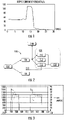
- FIG. 1 shows one of the aforementioned situations. As can be seen from the drawing, in a phase from the zero second to the 12th second, the transport refrigeration device operates normally, and the output of the generator is stabilized at about 50 amps.
- the engine of the transport vehicle is started, and a large amount of electrical energy needs to be taken from the battery.
- the electrical energy of the battery is taken from the generator, so the output of the generator is suddenly increased to 110 amps. Since the output current of the components used here is limited to 100 amps, the generator and the diesel engine that drives it are overloaded and shut down.
- US 2005/035657 A1 discloses a power management method for a transport refrigeration device as set out in the pre-characterising portion of claim 1.
- the present invention aims to provide a power management method for a transport refrigeration device with improved performance.
- the present invention also aims to provide a power management system for a transport refrigeration device with improved performance.
- the present invention further aims to provide a transport refrigeration device with improved performance.
- a power management method for a transport refrigeration device includes a power source, a compressor and a generator both driven by the power source, a refrigerant in a refrigeration circuit which is compressed by the compressor, a battery powered by the generator, an electrically driven component in the refrigeration circuit which is powered by the generator and/or the battery, and a control module
- the power management method includes: adjusting an output power of the power source and/or an input power of the compressor and/or charge and discharge statuses of the battery, by limiting an upper limit and/or a lower limit of an output power of the generator through the control module.
- the control module is communicatively coupled to the generator and the electrically driven component via a LIN bus.
- a start-up mode is included, wherein in the start-up mode, during the start-up of the power source, the control module limits the upper limit of the output power of the generator to a first upper limit threshold; after a rotational speed of the power source reaches a first start-up threshold, the control module releases the limiting of the upper limit of the output power of the generator to the first upper limit threshold; and wherein in the start-up mode, the battery supplies power to the electrically driven component in the refrigeration circuit.
- the first upper limit threshold is 0, and the first start-up threshold is 1000rpm.
- a normal mode is included, wherein in the normal mode, during the operation of the transport refrigeration device, the control module limits the upper limit of the output power of the generator to a second upper limit threshold, and limits the lower limit of the output power to a first lower limit threshold, so that the transport refrigeration device will not be overloaded.
- the second upper limit threshold is less than an overload power of the generator; and/or the first lower limit threshold is not less than a sum of a power required for operation of the electrically driven component in the refrigeration circuit and a preset charging power of the battery.
- a compressor high output capacity mode is included, wherein in the compressor high output capacity mode, the control module limits the upper limit of the output power of the generator to a third upper limit threshold, thereby increasing an output power supplied by the power source to the compressor; and wherein in the compressor high output capacity mode, the battery supplies power to the electrically driven component in the refrigeration circuit.
- control module sets and/or adjusts the third upper limit threshold based on a required input power of the compressor.
- the control module increases an opening degree of the compressor suction pressure regulating valve such that the output power of the compressor increases.
- an energy-saving mode is included, wherein in the energy-saving mode, the control module limits the upper limit of the output power of the generator to a fourth upper limit threshold; and/or in a case that the electrically driven component in the refrigeration circuit includes a compressor suction pressure regulating valve, the control module reduces an opening degree of the compressor suction pressure regulating valve such that the output power of the compressor decreases.
- the energy-saving mode is activated when a fuel reserve of the power source is lower than a fuel lower limit threshold.
- the power management method further includes a battery forced-charging mode, wherein in the battery forced-charging mode, when the voltage sensor senses that a voltage of the battery is lower than a voltage lower limit threshold, the control module limits the lower limit of the output power of the generator to a second lower limit threshold such that a portion of the output power of the generator is supplied to charge the battery.
- the second lower limit threshold is not less than a sum of a power required for operation of the electrically driven component in the refrigeration circuit and a preset charging power of the battery.
- a power source high-efficiency mode is included, wherein in the power source high-efficiency mode, a setting interval for high output power of the power source is acquired; when a required compressor input power and a generator input power are lower than a lower limit of the setting interval for high output power , the control module controls the power source to operate within the setting interval for high output power and charge the battery; and/or when the required compressor input power and the generator input power are higher than an upper limit of the setting interval for high output power , the control module controls the power source to operate within the setting interval for high output power, and uses the battery to supplement power to the electrically driven component in the refrigeration circuit.
- a power management system for a transport refrigeration device which is used for implementing the power management method as described above, the power management system including: a power source, which is configured to provide power; a compressor coupled to the power source and driven by the power source to compress a refrigerant in a refrigeration circuit; a generator coupled to the power source and driven by the power source to supply power to an electrically driven component in the refrigeration circuit; a battery coupled to the generator and configured to extract an electrical energy from the generator for charging, and to supply power to the electrically driven component in the refrigeration circuit; and a control module configured to adjust an output power of the power source and/or an input power of the compressor and/or charge and discharge statuses of the battery, by limiting an upper limit and/or a lower limit of an output power of the generator.
- the control module is communicatively coupled to the generator and the electrically driven component via a LIN bus.
- the electrically driven component includes one or more of a condenser fan, an evaporator fan, a compressor suction pressure regulating valve, and the control module.
- a voltage sensor is further included, which is coupled to the battery and configured to sense a voltage of the battery; and the control module controls the battery to charge and/or discharge, based on data sensed by the voltage sensor.
- the battery is also coupled to the electrically driven component of a transport vehicle of the transport refrigeration device.
- the power source drives the compressor and/or the generator via a belt and/or a transmission shaft.
- a transport refrigeration device which includes the power management system as described above.
- an output power of the power source and/or an input power of the compressor and/or charge and discharge statuses of the battery are adjusted by limiting an upper limit and/or a lower limit of an output power of the generator, so that a stable or efficient operation of each component can be realized in different modes or under different working conditions, thus improving the performance of the entire system.
- the present invention herein provides an embodiment of a power management system for a transport refrigeration device in connection with the drawings.
- the power management system 100 includes a power source 110, a compressor 120, a generator 130, a battery 140, and a control module 151.
- the power source 110 is configured to provide power; the compressor 120 coupled to the power source 110 is driven by the power source 110 to compress a refrigerant in a refrigeration circuit; the generator 130 coupled to the power source 110 is driven by the power source 110 to supply power to an electrically driven component 150 in the refrigeration circuit; the battery 140 coupled to the generator 130 is configured to extract an electrical energy from the generator 130 for charging, and to supply power to the electrically driven component 150 in the refrigeration circuit; and the control module 151 is configured to adjust an output power of the power source 110 and/or an input power of the compressor 120 and/or charge and discharge statuses of the battery 140, by limiting an upper limit and/or a lower limit of an output power of the generator 130.
- the power management system 100 for a transport refrigeration device can realize a stable or efficient operation of each component in different modes or under different working conditions, thus improving the performance of the entire system.
- the electrically driven component 150 mentioned in the foregoing embodiment may include one or more of a condenser fan 152, an evaporator fan 153, a compressor suction pressure regulating valve 154, or the control module 151.
- These electrically driven components 150 may require constant input power, and may also require variable input power.
- these fans can use gears of different wind speeds at different input powers.
- the system may also include a voltage sensor coupled to the battery 140 and configured to sense a voltage of the battery 140; and the control module 151 controls the battery 140 to charge and/or discharge, based on data sensed by the voltage sensor. This ensures that the battery can be in a stable voltage range and can perform charging and discharging operations as needed at any time.
- the battery 140 is also coupled to the electrically driven component 150 of a transport vehicle of the transport refrigeration device so that electrical energy can also be shared with the transport vehicle under certain circumstances.
- control module 151 is communicatively coupled to the generator 130 and the electrically driven component 150 via a LIN bus 160, thereby enabling communication among a plurality of components and control thereof.
- the power source 110 can drive the compressor 120 and the generator 130 via one or more of a belt and a transmission shaft.
- a transport refrigeration device is further provided herein, which includes the power management system 100 according to any of the foregoing embodiments or a combination thereof, and which also has corresponding technical effects.
- the present invention further provides a power management method for a transport refrigeration device in connection with the accompanying drawings, wherein the transport refrigeration device for implementing the method should include at least a power source 110, a compressor 120 and a generator 130 both driven by the power source 110, a refrigerant in a refrigeration circuit which is compressed by the compressor 120, a battery 140 powered by the generator 130, an electrically driven component 150 in the refrigeration circuit which is powered by the generator 130 and/or the battery 140, and a control module 151.
- the power management method includes: adjusting an output power of the power source 110 and/or an input power of the compressor 120 and/or charge and discharge statuses of the battery 140, by limiting an upper limit and/or a lower limit of an output power of the generator 130 and/or by adjusting an opening degree of a compressor suction pressure regulating valve through the control module 151.
- the power management system 100 for a transport refrigeration device can realize a stable or efficient operation of each component in different modes or under different working conditions, thus improving the performance of the entire system.
- a plurality of operation modes are specifically derived from the control method, thereby achieving performance improvement of different components from different perspectives, such as improving reliability or increasing efficiency thereof.
- a start-up mode may be included, wherein in the start-up mode, during the start-up of the power source 100, the control module 151 limits the upper limit of the output power of the generator 130 to the electrically driven component 150 to a first upper limit threshold; after a rotational speed of the power source 110 reaches a first start-up threshold, the control module 151 releases the limiting of the upper limit of the output power of the generator 130 to the first upper limit threshold.
- the power source 110 has a lower start-up load so that it can be successfully started more easily.
- the battery 140 should be simultaneously controlled to supply power to the electrically driven component 150 in the refrigeration circuit.
- the first upper limit threshold can be set to zero, at which point the power source 110 will have a lower start-up load and is therefore more likely to be successfully started.
- the first start-up threshold can also be set to 1000rpm, that is, after this rotational speed is reached, the power source can be considered to have successfully started.
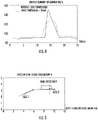
- the solid lines show the rotational speed of a diesel engine serving as the power source
- the dashed lines show the output current of the generator.
- the output current of the generator is limited to 0 amp, so that the diesel engine can be started smoothly with a small load until the rotational speed exceeds 1000 rpm, and then the limiting of the output current of the generator is released so that the generator can start working normally.
- the power management method may further include a normal mode, wherein in the normal mode, during the operation of the transport refrigeration device, the control module 151 limits the upper limit of the output power of the generator 130 to a second upper limit threshold, and limits the lower limit of the output power to a first lower limit threshold. More specifically, the second upper limit threshold is less than an overload power of the generator 130, and the first lower limit threshold is not less than a sum of a power required for operation of the electrically driven component 150 in the refrigeration circuit and a preset charging power of the battery 140.
- the lowest output power provided by the generator 130 can ensure that the electrically driven components 150 in the refrigeration circuit can operate normally, and it is also possible to ensure that the battery 140 can obtain a part of the charging capacity; on the other hand, the highest output power provided by the generator 130 is lower than the overload condition of the diesel engine, so even if a special condition occurs in which the transport vehicle borrows electricity from the battery, the overload problem will not be caused.
- the solid lines show a situation where the output current of the generator is not limited
- the dashed line show a situation where the output current of the generator is limited.
- the power management method may further include a compressor high output capacity mode, wherein in the compressor high output capacity mode, the control module 151 limits the upper limit of the output power of the generator 130 to a third upper limit threshold, thereby increasing an output power supplied by the power source 110 to the compressor 120; and wherein in the compressor high output capacity mode, the battery 140 supplies power to the electrically driven component 150 in the refrigeration circuit.
- the control module 151 can set or adjust a third upper limit threshold output by the generator 130, and can even set the third upper limit threshold to 0, thereby ensuring that the output capacity of the compressor can meet requirements.
- the generator will provide an output current of 75 amps, thus meeting the requirements of supplying power to the electrically driven components in the refrigeration circuit and the battery. Moreover, at this point, the compressor outputs a power of 5,122 watts, and finally outputs a refrigeration capacity of 9,419 watts.
- the output current of the generator is continuously reduced at different gears in the high output capacity mode, and accordingly, the output power of the compressor is also continuously increased, thereby improving the refrigeration capacity of the refrigeration circuit.
- the output current of the generator is about 80% of the reference, and the refrigeration capacity is increased by about 7% compared with the reference; since the battery usually occupies 20 amps of current for charging, the battery in the mode A is substantially in a state of neither charging nor discharging.
- a compressor high output capacity mode B the output current of the generator is about 60% of the reference, and the refrigeration capacity is increased by about 14% compared with the reference; in a compressor high output capacity mode C, the output current of the generator is about 40% of the reference, and the refrigeration capacity is increased by about 21% compared with the reference; in a compressor high output capacity mode D, the output current of the generator is about 20% of the reference, and the refrigeration capacity is increased by about 28% compared with the reference; and in a compressor high output capacity mode E, the output current of the generator is about 0, and the refrigeration capacity is increased by about 35% compared with the reference; at this point, the output power of the power source occupied by the generator is almost zero, that is, the compressor and the driven refrigeration circuit almost achieve the highest refrigeration capacity under the current working condition.
- the generator will provide an output current of 75 amps, thus meeting the requirements of supplying power to the electrically driven components in the refrigeration circuit and the battery. Moreover, at this point, the compressor outputs a power of 4,331 watts, and finally outputs a refrigeration capacity of 6,879 watts.
- the output current of the generator is continuously reduced at different gears in the high output capacity mode, and accordingly, the output power of the compressor is also continuously increased, thereby improving the refrigeration capacity of the refrigeration circuit.
- the output current of the generator is about 80% of the reference, and the refrigeration capacity is increased by about 8.6% compared with the reference; since the battery usually occupies 20 amps of current for charging, the battery in the mode A is substantially in a state of neither charging nor discharging.
- a compressor high output capacity mode B the output current of the generator is about 60% of the reference, and the refrigeration capacity is increased by about 17.5% compared with the reference; in a compressor high output capacity mode C, the output current of the generator is about 40% of the reference, and the refrigeration capacity is increased by about 26.5% compared with the reference; in a compressor high output capacity mode D, the output current of the generator is about 20% of the reference, and the refrigeration capacity is increased by about 35.7% compared with the reference; and in a compressor high output capacity mode E, the output current of the generator is about 0, and the refrigeration capacity is increased by about 40.2% compared with the reference; at this point, the output power of the power source occupied by the generator is almost zero, that is, the compressor and the driven refrigeration circuit almost achieve the highest refrigeration capacity under the current working condition.
- the power management method may further include an energy-saving mode, wherein in the energy-saving mode, the control module 151 limits the upper limit of the output power of the generator 130 to a fourth upper limit threshold, or even limits it to 0; or in a case that the electrically driven component 150 in the refrigeration circuit includes a compressor suction pressure regulating valve 154, the control module 151 reduces an opening degree of the compressor suction pressure regulating valve 154 such that the output power of the compressor 120 decreases.
- the energy-saving mode is typically activated when a fuel reserve of the power source 110 is lower than a fuel lower limit threshold.
- the power management method may further include a battery forced-charging mode, wherein in the battery forced-charging mode, when the voltage sensor senses that a voltage of the battery 140 is lower than a voltage lower limit threshold, the control module 151 limits the lower limit of the output power of the generator 130 to a second lower limit threshold (for example, the second lower limit threshold is not less than a sum of a power required for operation of the electrically driven component 150 in the refrigeration circuit and a preset charging power of the battery 140) such that a portion of the output power of the generator 130 is supplied to charge the battery 140.
- a second lower limit threshold for example, the second lower limit threshold is not less than a sum of a power required for operation of the electrically driven component 150 in the refrigeration circuit and a preset charging power of the battery 140
- the power management method may further include a power source high-efficiency mode, wherein in the power source high-efficiency mode, a setting interval for high output power of the power source 110 is acquired, such as the block interval above the curve as shown.
- a setting interval for high output power of the power source 110 is acquired, such as the block interval above the curve as shown.
- the control module 151 controls the power source 110 to operate within the setting interval for high output power, drive the generator by using the excessive output power, and further charge the battery 140.
- the control module 151 controls the power source 110 to operate within the setting interval for high output power , and uses the battery 140 to supplement power to the electrically driven component 150 in the refrigeration circuit.
- the diesel engine serving as the power source is always in a high-efficiency operation state, and the maximum output power can be generated in unit fuel consumption.
Landscapes
- Engineering & Computer Science (AREA)
- Physics & Mathematics (AREA)
- Mechanical Engineering (AREA)
- Thermal Sciences (AREA)
- General Engineering & Computer Science (AREA)
- Devices That Are Associated With Refrigeration Equipment (AREA)
Claims (15)
- Leistungsverwaltungsverfahren für eine Transportkühlvorrichtung, wobei die Transportkühlvorrichtung eine Leistungsquelle (110), einen Kompressor (120) und einen Generator (130), die beide von der Leistungsquelle (110) angetrieben werden, einen Kühlkreislauf, der den Kompressor (120) und eine elektrisch betriebene Komponente (150), eine von dem Generator (130) mit Strom versorgte Batterie (140) umfasst, und ein Steuermodul (151) umfasst, und die elektrisch angetriebene Komponente (150) von dem Generator (130) und/oder der Batterie (140) mit Strom versorgt wird, wobei das Leistungsverwaltungsverfahren Folgendes umfasst:Regulieren einer Ausgangsleistung der Leistungsquelle (110) und/oder einer Eingangsleistung des Kompressors (120) und/oder von Lade- und Entladezuständen der Batterie (140) durch Begrenzen eines oberen Grenzwerts und/oder eines unteren Grenzwerts einer Ausgangsleistung des Generators (130) durch das Steuermodul (151),dadurch gekennzeichnet, dass:
das Steuermodul (151) kommunizierend mit dem Generator (130) und der elektrisch angetriebenen Komponente (150) über einen LIN-Bus (160) gekoppelt ist. - Leistungsverwaltungsverfahren nach Anspruch 1, umfassend einen Anlaufmodus:während des Anlaufs der Leistungsquelle (110) begrenzt das Steuermodul (151) den oberen Grenzwert der Ausgangsleistung des Generators (130) auf einen ersten oberen Grenzwertschwellenwert;nachdem eine Rotationsgeschwindigkeit der Leistungsquelle (110) einen ersten Anlaufschwellenwert erreicht, hebt das Steuermodul (151) Begrenzen des oberen Grenzwerts der Ausgangsleistung des Generators (130) auf den ersten oberen Grenzwertschwellenwert auf; undin dem Anlaufmodus gibt die Batterie (140) Leistung an die elektrisch angetriebene Komponente (150) in dem Kühlkreislauf ab.
- Leistungsverwaltungsverfahren nach Anspruch 2, wobei der erste obere Grenzwertschwellenwert 0 ist, und der erste Anlaufschwellenwert 1000 U/min ist.
- Leistungsverwaltungsverfahren nach Anspruch 1, umfassend einen normalen Modus:während des Betriebs der Transportkühlvorrichtung begrenzt das Steuermodul (151) den oberen Grenzwert der Ausgangsleistung des Generators (130) auf einen zweiten oberen Grenzwertschwellenwert und begrenzt den unteren Grenzwert der Ausgangsleistung auf einen ersten unteren Grenzwertschwellenwert, so dass die Transportkühlvorrichtung nicht überlastet wird,wobei der zweite obere Grenzwertschwellenwert optional geringer ist als eine Überlastungsleistung des Generators (130); und/oder der erste untere Grenzwertschwellenwert nicht geringer ist als eine Summe einer Leistung, die für den Betrieb der elektrisch angetriebenen Komponente (150) in dem Kühlkreislauf erforderlich ist, und einer voreingestellten Ladeleistung der Batterie (140).
- Leistungsverwaltungsverfahren nach Anspruch 1, umfassend einen Modus mit hoher Ausgabeleistung des Kompressors (120): das Steuermodul (151) begrenzt den oberen Grenzwert der Ausgangsleistung des Generators (130) auf einen dritten oberen Grenzwertschwellenwert und erhöht dadurch eine von der Leistungsquelle (110) an den Kompressor (120) abgegebene Ausgangsleistung; undin dem Modus mit hoher Ausgabeleistung des Kompressors (120) gibt die Batterie (140) Leistung an die elektrisch angetriebene Komponente (150) in dem Kühlkreislauf ab,wobei das Steuermodul (151) optional den dritten oberen Grenzwertschwellenwert basierend auf einer erforderlichen Eingangsleistung des Kompressors (120) einstellt und/oder reguliert.
- Leistungsverwaltungsverfahren nach Anspruch 5, wobei die elektrisch angetriebene Komponente (150) in dem Kühlkreislauf ein Kompressor-Ansaugdruckregelventil (154) umfasst und das Steuermodul (151) einen Öffnungsgrad des Kompressor-Ansaugdruckregelventils (154) so vergrößert, dass die Ausgangsleistung des Kompressors (120) erhöht wird.
- Leistungsverwaltungsverfahren nach Anspruch 1, wobei die elektrisch angetriebene Komponente (150) in dem Kühlkreislauf ein Kompressor-Ansaugdruckregelventil (154) umfasst und das Leistungsverwaltungsverfahren einen Energiesparmodus umfasst:das Steuermodul (151) begrenzt den oberen Grenzwert der Ausgangsleistung des Generators (130) auf einen vierten oberen Grenzwertschwellenwert; und/oderdas Steuermodul (151) verringert einen Öffnungsgrad des Kompressor-Ansaugdruckregelventils (154) so, dass die Ausgangsleistung des Kompressors (120) verringert wird,wobei der Energiesparmodus optional aktiviert wird, wenn eine Kraftstoffreserve der Leistungsquelle (110) niedriger ist als ein untere Kraftstoffgrenzwertschwellenwert.
- Leistungsverwaltungsverfahren nach Anspruch 1, wobei die Transportkühlvorrichtung weiter einen Spannungssensor umfasst, der mit der Batterie (140) gekoppelt ist, und das Leistungsverwaltungsverfahren weiter einen Batterie-Zwangslademodus umfasst:wenn der Spannungssensor erkennt, dass eine Spannung der Batterie (140) niedriger ist als ein unterer Spannungsgrenzwertschwellenwert, begrenzt das Steuermodul (151) den unteren Grenzwerts der Ausgangsleistung des Generators (130) auf einen zweiten unteren Grenzwertschwellenwert so, dass ein Teil der Ausgangsleistung des Generators (130) zum Laden der Batterie (140) abgegeben wird,wobei der zweite untere Grenzwertschwellen optional nicht geringer ist als eine Summe einer Leistung, die für den Betrieb der elektrisch angetriebenen Komponente (150) in dem Kühlkreislauf erforderlich ist, und einer voreingestellten Ladeleistung der Batterie (140).
- Leistungsverwaltungsverfahren nach Anspruch 1, umfassend a Hocheffizienzmodus der Leistungsquelle:ein Einstellungsintervall für hohe Ausgangsleistung der Leistungsquelle (110) wird erfasst;wenn eine erforderliche Eingangsleistung des Kompressors (120) und eine Eingangsleistung des Generators (130) geringer sind als ein unterer Grenzwert des Einstellungsintervalls für hohe Ausgangsleistung, steuert das Steuermodul (151) die Leistungsquelle (110), um mit dem Einstellungsintervall für hohe Ausgangsleistung zu arbeiten und die Batterie (140) zu laden; und/oderwenn die erforderliche Eingangsleistung des Kompressors (120) und eine Eingangsleistung des Generators (130) höher sind als ein obere Grenzwert des Einstellungsintervalls für hohe Ausgangsleistung, steuert das Steuermodul (151) die Leistungsquelle (110), um mit dem Einstellungsintervall für hohe Ausgangsleistung zu arbeiten, und verwendet die Batterie (140), um Leistung an die elektrisch angetriebene Komponente (150) in dem Kühlkreislauf zu ergänzen.
- Leistungsverwaltungssystem (100) für eine Transportkühlvorrichtung, das zum Implementieren des Leistungsverwaltungsverfahrens nach einem der Ansprüche 1 bis 9 verwendet wird, wobei das Leistungsverwaltungssystem Folgendes umfasst:eine Leistungsquelle (110), die konfiguriert ist, um Leistung bereitzustellen;einen Kompressor (120), der mit der Leistungsquelle (110) gekoppelt ist und von der Leistungsquelle (110) angetrieben wird, um ein Kühlmittel in einem Kühlkreislauf zu komprimieren;einen Generator (130), der mit der Leistungsquelle (110) gekoppelt ist und von der Leistungsquelle (110) angetrieben wird, um Leistung an eine elektrisch angetriebene Komponente (150) in dem Kühlkreislauf abzugeben;eine Batterie (140), die mit dem Generator (130) gekoppelt ist und konfiguriert ist, um zum Laden elektrische Energie aus dem Generator (130) zu entnehmen und Leistung an die elektrisch angetriebene Komponente (150) in dem Kühlkreislauf abzugeben; undein Steuermodul (151), das konfiguriert ist, um eine Ausgangsleistung der Leistungsquelle (110) und/oder eine Eingangsleistung des Kompressors (120) und/oder Lade- und Entladezustände der Batterie (140) zu regulieren durch Begrenzen eines oberen Grenzwerts und/oder eines unteren Grenzwerts einer Ausgangsleistung des Generators (130),dadurch gekennzeichnet, dass:
das Steuermodul (151) kommunizierend mit dem Generator (130) und der elektrisch angetriebenen Komponente (150) über einen LIN-Bus (160) gekoppelt ist. - Leistungsverwaltungssystem (100) nach Anspruch 10, wobei die elektrisch angetriebene Komponente (150) eines oder mehreres von einem Kondensatorlüfter (152), einem Verdampferlüfter (153), einem Kompressor-Ansaugdruckregelventil (154) und das Steuermodul (151) umfasst.
- Leistungsverwaltungssystem (100) nach Anspruch 10, weiter umfassend einen Spannungssensor, der mit der Batterie (140) gekoppelt ist und konfiguriert ist, um eine Spannung der Batterie (140) zu erkennen; und wobei das Steuermodul (151) die Batterie (140) basierend auf von dem Spannungssensor erkannten Daten zum Laden und/oder Entladen steuert.
- Leistungsverwaltungssystem (100) nach Anspruch 10, wobei die Batterie (140) auch mit der elektrisch angetriebenen Komponente (150) eines Transportfahrzeugs der Transportkühlvorrichtung gekoppelt ist.
- Leistungsverwaltungssystem (100) nach Anspruch 10, wobei die Leistungsquelle (110) den Kompressor (120) und/oder den Generator (130) über einen Riemen und/oder eine Transmissionswelle antreibt.
- Transportkühlvorrichtung, umfassend das Leistungsverwaltungssystem (100) nach einem der Ansprüche 10 bis 14.
Applications Claiming Priority (2)
| Application Number | Priority Date | Filing Date | Title |
|---|---|---|---|
| CN201811073683.8A CN110906596A (zh) | 2018-09-14 | 2018-09-14 | 运输制冷装置、及其动力管理系统及动力管理方法 |
| PCT/US2019/049961 WO2020055689A1 (en) | 2018-09-14 | 2019-09-06 | Transportation refrigeration device, power management system and power management method |
Publications (2)
| Publication Number | Publication Date |
|---|---|
| EP3849832A1 EP3849832A1 (de) | 2021-07-21 |
| EP3849832B1 true EP3849832B1 (de) | 2023-01-04 |
Family
ID=68000111
Family Applications (1)
| Application Number | Title | Priority Date | Filing Date |
|---|---|---|---|
| EP19773270.4A Active EP3849832B1 (de) | 2018-09-14 | 2019-09-06 | Transportkühlvorrichtung, leistungsverwaltungssystem und leistungsverwaltungsverfahren |
Country Status (4)
| Country | Link |
|---|---|
| US (1) | US20210229529A1 (de) |
| EP (1) | EP3849832B1 (de) |
| CN (1) | CN110906596A (de) |
| WO (1) | WO2020055689A1 (de) |
Families Citing this family (7)
| Publication number | Priority date | Publication date | Assignee | Title |
|---|---|---|---|---|
| DE102017214941A1 (de) * | 2017-08-25 | 2019-02-28 | Dometic Sweden Ab | Freizeitfahrzeug, Kühlvorrichtung, Steuerungssystem und Verfahren zur Steuerung der Kühlvorrichtung |
| EP3971661A1 (de) | 2020-09-18 | 2022-03-23 | Dometic Sweden AB | System und verfahren zur steuerung mindestens einer funktion eines fahrzeugs |
| EP3971691A1 (de) | 2020-09-18 | 2022-03-23 | Dometic Sweden AB | Wohnmobilbenutzerschnittstelle |
| EP3972314A1 (de) | 2020-09-18 | 2022-03-23 | Dometic Sweden AB | Vorrichtungen und verfahren zur sicherung der kommunikation zwischen einem sensor und einer vorrichtung |
| CN116080340B (zh) * | 2022-12-30 | 2025-09-05 | 中联重科股份有限公司 | 电平衡的控制方法、控制装置及起重机 |
| WO2025196670A1 (en) * | 2024-03-20 | 2025-09-25 | Howard Rosen | System and method for power saving generator control |
| CN119527359B (zh) * | 2024-11-27 | 2025-11-18 | 中车长江运输设备集团有限公司 | 油电混动系统的控制方法、油电混动系统和冷链运输车辆 |
Family Cites Families (7)
| Publication number | Priority date | Publication date | Assignee | Title |
|---|---|---|---|---|
| JPS59102615A (ja) * | 1982-12-02 | 1984-06-13 | Diesel Kiki Co Ltd | 車輌の冷房システムの制御方法 |
| JP2973796B2 (ja) * | 1993-10-07 | 1999-11-08 | トヨタ自動車株式会社 | ハイブリッド電気自動車の空調制御方法 |
| US7259469B2 (en) * | 2003-07-31 | 2007-08-21 | Scs Frigette Inc. | Vehicle auxiliary power unit, assembly, and related methods |
| CN101898500B (zh) * | 2010-07-19 | 2011-12-07 | 浙江博阳压缩机有限公司 | 直流电驱动移动制冷设备 |
| CN103476613B (zh) * | 2011-04-04 | 2018-04-27 | 开利公司 | 半电动移动制冷系统 |
| JP6347235B2 (ja) * | 2015-07-30 | 2018-06-27 | トヨタ自動車株式会社 | ハイブリッド車両の制御装置 |
| CN207028771U (zh) * | 2017-06-21 | 2018-02-23 | 山东通盛制冷设备有限公司 | 一种纯电动车制冷、供电控制系统 |
-
2018
- 2018-09-14 CN CN201811073683.8A patent/CN110906596A/zh active Pending
-
2019
- 2019-09-06 EP EP19773270.4A patent/EP3849832B1/de active Active
- 2019-09-06 US US15/734,478 patent/US20210229529A1/en not_active Abandoned
- 2019-09-06 WO PCT/US2019/049961 patent/WO2020055689A1/en not_active Ceased
Also Published As
| Publication number | Publication date |
|---|---|
| CN110906596A (zh) | 2020-03-24 |
| US20210229529A1 (en) | 2021-07-29 |
| EP3849832A1 (de) | 2021-07-21 |
| WO2020055689A1 (en) | 2020-03-19 |
Similar Documents
| Publication | Publication Date | Title |
|---|---|---|
| US20210229529A1 (en) | Transportation refrigeration device, power management system and power management method | |
| EP2689944B1 (de) | Kühlsystem für Transportzwecke | |
| US20080179887A1 (en) | Hybrid power generation of wind-power generator and battery energy storage system | |
| US7106030B2 (en) | Field excitation for an alternator | |
| US20030113595A1 (en) | Fuel cell system power control method and system | |
| US20200130532A1 (en) | Method and system for power management using a power converter in transport | |
| KR20160003824A (ko) | 전력 구동 시스템 | |
| US20050162146A1 (en) | Control circuit apparatus and power supply circuit control method | |
| CN114024008A (zh) | 一种多堆燃料电池系统功率管理集成装置及其工作方法 | |
| CN114244287B (zh) | 一种调节电路和电子设备 | |
| JP2002218654A (ja) | 太陽光発電システム | |
| JP6987292B1 (ja) | 充放電制御装置、充放電制御プログラム | |
| CN113071372B (zh) | 功率半跟随式燃料电池混合动力汽车能量管理方法 | |
| JP3516108B2 (ja) | スクリュー圧縮機及びその制御方法 | |
| CN118322947A (zh) | 一种氢燃料电池动力系统的智能能量优化控制装置及方法 | |
| JP3968913B2 (ja) | 電源装置および電源装置の制御方法 | |
| CN110912496B (zh) | 一种断路器储能电机的控制方法及装置 | |
| US12184115B2 (en) | System and method for managing electrical power drawn from a vehicle alternator | |
| KR100826149B1 (ko) | 소화기 사격통제장치용 순간 고 전력 전원공급장치 및 방법 | |
| KR102015291B1 (ko) | 순간 고출력 하이브리드 bms 전지 팩 시스템 | |
| CN116742641A (zh) | 一种热泵的电源系统及热泵系统 | |
| JP3030133B2 (ja) | 系統連系型太陽光発電装置 | |
| KR102204470B1 (ko) | 전동모터와 유압모터를 결합한 하이브리드 냉각시스템 | |
| JP4912688B2 (ja) | 交流電動機用速度制御機の直流バス上の電圧管理方法およびシステム | |
| CN112271775A (zh) | 电源供应装置及其电源供应方法 |
Legal Events
| Date | Code | Title | Description |
|---|---|---|---|
| STAA | Information on the status of an ep patent application or granted ep patent |
Free format text: STATUS: UNKNOWN |
|
| STAA | Information on the status of an ep patent application or granted ep patent |
Free format text: STATUS: THE INTERNATIONAL PUBLICATION HAS BEEN MADE |
|
| PUAI | Public reference made under article 153(3) epc to a published international application that has entered the european phase |
Free format text: ORIGINAL CODE: 0009012 |
|
| STAA | Information on the status of an ep patent application or granted ep patent |
Free format text: STATUS: REQUEST FOR EXAMINATION WAS MADE |
|
| 17P | Request for examination filed |
Effective date: 20201202 |
|
| AK | Designated contracting states |
Kind code of ref document: A1 Designated state(s): AL AT BE BG CH CY CZ DE DK EE ES FI FR GB GR HR HU IE IS IT LI LT LU LV MC MK MT NL NO PL PT RO RS SE SI SK SM TR |
|
| DAV | Request for validation of the european patent (deleted) | ||
| DAX | Request for extension of the european patent (deleted) | ||
| GRAP | Despatch of communication of intention to grant a patent |
Free format text: ORIGINAL CODE: EPIDOSNIGR1 |
|
| STAA | Information on the status of an ep patent application or granted ep patent |
Free format text: STATUS: GRANT OF PATENT IS INTENDED |
|
| INTG | Intention to grant announced |
Effective date: 20220905 |
|
| GRAS | Grant fee paid |
Free format text: ORIGINAL CODE: EPIDOSNIGR3 |
|
| GRAA | (expected) grant |
Free format text: ORIGINAL CODE: 0009210 |
|
| STAA | Information on the status of an ep patent application or granted ep patent |
Free format text: STATUS: THE PATENT HAS BEEN GRANTED |
|
| AK | Designated contracting states |
Kind code of ref document: B1 Designated state(s): AL AT BE BG CH CY CZ DE DK EE ES FI FR GB GR HR HU IE IS IT LI LT LU LV MC MK MT NL NO PL PT RO RS SE SI SK SM TR |
|
| REG | Reference to a national code |
Ref country code: GB Ref legal event code: FG4D |
|
| REG | Reference to a national code |
Ref country code: DE Ref legal event code: R096 Ref document number: 602019024016 Country of ref document: DE |
|
| REG | Reference to a national code |
Ref country code: CH Ref legal event code: EP |
|
| REG | Reference to a national code |
Ref country code: AT Ref legal event code: REF Ref document number: 1541688 Country of ref document: AT Kind code of ref document: T Effective date: 20230115 |
|
| REG | Reference to a national code |
Ref country code: IE Ref legal event code: FG4D |
|
| REG | Reference to a national code |
Ref country code: LT Ref legal event code: MG9D |
|
| REG | Reference to a national code |
Ref country code: NL Ref legal event code: MP Effective date: 20230104 |
|
| REG | Reference to a national code |
Ref country code: AT Ref legal event code: MK05 Ref document number: 1541688 Country of ref document: AT Kind code of ref document: T Effective date: 20230104 |
|
| PG25 | Lapsed in a contracting state [announced via postgrant information from national office to epo] |
Ref country code: NL Free format text: LAPSE BECAUSE OF FAILURE TO SUBMIT A TRANSLATION OF THE DESCRIPTION OR TO PAY THE FEE WITHIN THE PRESCRIBED TIME-LIMIT Effective date: 20230104 |
|
| PG25 | Lapsed in a contracting state [announced via postgrant information from national office to epo] |
Ref country code: RS Free format text: LAPSE BECAUSE OF FAILURE TO SUBMIT A TRANSLATION OF THE DESCRIPTION OR TO PAY THE FEE WITHIN THE PRESCRIBED TIME-LIMIT Effective date: 20230104 Ref country code: PT Free format text: LAPSE BECAUSE OF FAILURE TO SUBMIT A TRANSLATION OF THE DESCRIPTION OR TO PAY THE FEE WITHIN THE PRESCRIBED TIME-LIMIT Effective date: 20230504 Ref country code: NO Free format text: LAPSE BECAUSE OF FAILURE TO SUBMIT A TRANSLATION OF THE DESCRIPTION OR TO PAY THE FEE WITHIN THE PRESCRIBED TIME-LIMIT Effective date: 20230404 Ref country code: LV Free format text: LAPSE BECAUSE OF FAILURE TO SUBMIT A TRANSLATION OF THE DESCRIPTION OR TO PAY THE FEE WITHIN THE PRESCRIBED TIME-LIMIT Effective date: 20230104 Ref country code: LT Free format text: LAPSE BECAUSE OF FAILURE TO SUBMIT A TRANSLATION OF THE DESCRIPTION OR TO PAY THE FEE WITHIN THE PRESCRIBED TIME-LIMIT Effective date: 20230104 Ref country code: HR Free format text: LAPSE BECAUSE OF FAILURE TO SUBMIT A TRANSLATION OF THE DESCRIPTION OR TO PAY THE FEE WITHIN THE PRESCRIBED TIME-LIMIT Effective date: 20230104 Ref country code: ES Free format text: LAPSE BECAUSE OF FAILURE TO SUBMIT A TRANSLATION OF THE DESCRIPTION OR TO PAY THE FEE WITHIN THE PRESCRIBED TIME-LIMIT Effective date: 20230104 Ref country code: AT Free format text: LAPSE BECAUSE OF FAILURE TO SUBMIT A TRANSLATION OF THE DESCRIPTION OR TO PAY THE FEE WITHIN THE PRESCRIBED TIME-LIMIT Effective date: 20230104 |
|
| PG25 | Lapsed in a contracting state [announced via postgrant information from national office to epo] |
Ref country code: SE Free format text: LAPSE BECAUSE OF FAILURE TO SUBMIT A TRANSLATION OF THE DESCRIPTION OR TO PAY THE FEE WITHIN THE PRESCRIBED TIME-LIMIT Effective date: 20230104 Ref country code: PL Free format text: LAPSE BECAUSE OF FAILURE TO SUBMIT A TRANSLATION OF THE DESCRIPTION OR TO PAY THE FEE WITHIN THE PRESCRIBED TIME-LIMIT Effective date: 20230104 Ref country code: IS Free format text: LAPSE BECAUSE OF FAILURE TO SUBMIT A TRANSLATION OF THE DESCRIPTION OR TO PAY THE FEE WITHIN THE PRESCRIBED TIME-LIMIT Effective date: 20230504 Ref country code: GR Free format text: LAPSE BECAUSE OF FAILURE TO SUBMIT A TRANSLATION OF THE DESCRIPTION OR TO PAY THE FEE WITHIN THE PRESCRIBED TIME-LIMIT Effective date: 20230405 Ref country code: FI Free format text: LAPSE BECAUSE OF FAILURE TO SUBMIT A TRANSLATION OF THE DESCRIPTION OR TO PAY THE FEE WITHIN THE PRESCRIBED TIME-LIMIT Effective date: 20230104 |
|
| REG | Reference to a national code |
Ref country code: DE Ref legal event code: R097 Ref document number: 602019024016 Country of ref document: DE |
|
| PG25 | Lapsed in a contracting state [announced via postgrant information from national office to epo] |
Ref country code: SM Free format text: LAPSE BECAUSE OF FAILURE TO SUBMIT A TRANSLATION OF THE DESCRIPTION OR TO PAY THE FEE WITHIN THE PRESCRIBED TIME-LIMIT Effective date: 20230104 Ref country code: RO Free format text: LAPSE BECAUSE OF FAILURE TO SUBMIT A TRANSLATION OF THE DESCRIPTION OR TO PAY THE FEE WITHIN THE PRESCRIBED TIME-LIMIT Effective date: 20230104 Ref country code: EE Free format text: LAPSE BECAUSE OF FAILURE TO SUBMIT A TRANSLATION OF THE DESCRIPTION OR TO PAY THE FEE WITHIN THE PRESCRIBED TIME-LIMIT Effective date: 20230104 Ref country code: DK Free format text: LAPSE BECAUSE OF FAILURE TO SUBMIT A TRANSLATION OF THE DESCRIPTION OR TO PAY THE FEE WITHIN THE PRESCRIBED TIME-LIMIT Effective date: 20230104 Ref country code: CZ Free format text: LAPSE BECAUSE OF FAILURE TO SUBMIT A TRANSLATION OF THE DESCRIPTION OR TO PAY THE FEE WITHIN THE PRESCRIBED TIME-LIMIT Effective date: 20230104 |
|
| PLBE | No opposition filed within time limit |
Free format text: ORIGINAL CODE: 0009261 |
|
| STAA | Information on the status of an ep patent application or granted ep patent |
Free format text: STATUS: NO OPPOSITION FILED WITHIN TIME LIMIT |
|
| PG25 | Lapsed in a contracting state [announced via postgrant information from national office to epo] |
Ref country code: SK Free format text: LAPSE BECAUSE OF FAILURE TO SUBMIT A TRANSLATION OF THE DESCRIPTION OR TO PAY THE FEE WITHIN THE PRESCRIBED TIME-LIMIT Effective date: 20230104 |
|
| 26N | No opposition filed |
Effective date: 20231005 |
|
| PG25 | Lapsed in a contracting state [announced via postgrant information from national office to epo] |
Ref country code: SI Free format text: LAPSE BECAUSE OF FAILURE TO SUBMIT A TRANSLATION OF THE DESCRIPTION OR TO PAY THE FEE WITHIN THE PRESCRIBED TIME-LIMIT Effective date: 20230104 |
|
| P01 | Opt-out of the competence of the unified patent court (upc) registered |
Effective date: 20240119 |
|
| REG | Reference to a national code |
Ref country code: CH Ref legal event code: PL |
|
| PG25 | Lapsed in a contracting state [announced via postgrant information from national office to epo] |
Ref country code: LU Free format text: LAPSE BECAUSE OF NON-PAYMENT OF DUE FEES Effective date: 20230906 |
|
| REG | Reference to a national code |
Ref country code: BE Ref legal event code: MM Effective date: 20230930 |
|
| PG25 | Lapsed in a contracting state [announced via postgrant information from national office to epo] |
Ref country code: LU Free format text: LAPSE BECAUSE OF NON-PAYMENT OF DUE FEES Effective date: 20230906 Ref country code: IT Free format text: LAPSE BECAUSE OF FAILURE TO SUBMIT A TRANSLATION OF THE DESCRIPTION OR TO PAY THE FEE WITHIN THE PRESCRIBED TIME-LIMIT Effective date: 20230104 Ref country code: MC Free format text: LAPSE BECAUSE OF FAILURE TO SUBMIT A TRANSLATION OF THE DESCRIPTION OR TO PAY THE FEE WITHIN THE PRESCRIBED TIME-LIMIT Effective date: 20230104 |
|
| REG | Reference to a national code |
Ref country code: IE Ref legal event code: MM4A |
|
| PG25 | Lapsed in a contracting state [announced via postgrant information from national office to epo] |
Ref country code: IE Free format text: LAPSE BECAUSE OF NON-PAYMENT OF DUE FEES Effective date: 20230906 |
|
| PG25 | Lapsed in a contracting state [announced via postgrant information from national office to epo] |
Ref country code: CH Free format text: LAPSE BECAUSE OF NON-PAYMENT OF DUE FEES Effective date: 20230930 |
|
| PG25 | Lapsed in a contracting state [announced via postgrant information from national office to epo] |
Ref country code: IE Free format text: LAPSE BECAUSE OF NON-PAYMENT OF DUE FEES Effective date: 20230906 Ref country code: CH Free format text: LAPSE BECAUSE OF NON-PAYMENT OF DUE FEES Effective date: 20230930 |
|
| PG25 | Lapsed in a contracting state [announced via postgrant information from national office to epo] |
Ref country code: BE Free format text: LAPSE BECAUSE OF NON-PAYMENT OF DUE FEES Effective date: 20230930 |
|
| PG25 | Lapsed in a contracting state [announced via postgrant information from national office to epo] |
Ref country code: BG Free format text: LAPSE BECAUSE OF FAILURE TO SUBMIT A TRANSLATION OF THE DESCRIPTION OR TO PAY THE FEE WITHIN THE PRESCRIBED TIME-LIMIT Effective date: 20230104 |
|
| PG25 | Lapsed in a contracting state [announced via postgrant information from national office to epo] |
Ref country code: BG Free format text: LAPSE BECAUSE OF FAILURE TO SUBMIT A TRANSLATION OF THE DESCRIPTION OR TO PAY THE FEE WITHIN THE PRESCRIBED TIME-LIMIT Effective date: 20230104 |
|
| PG25 | Lapsed in a contracting state [announced via postgrant information from national office to epo] |
Ref country code: CY Free format text: LAPSE BECAUSE OF FAILURE TO SUBMIT A TRANSLATION OF THE DESCRIPTION OR TO PAY THE FEE WITHIN THE PRESCRIBED TIME-LIMIT; INVALID AB INITIO Effective date: 20190906 |
|
| PG25 | Lapsed in a contracting state [announced via postgrant information from national office to epo] |
Ref country code: HU Free format text: LAPSE BECAUSE OF FAILURE TO SUBMIT A TRANSLATION OF THE DESCRIPTION OR TO PAY THE FEE WITHIN THE PRESCRIBED TIME-LIMIT; INVALID AB INITIO Effective date: 20190906 |
|
| PGFP | Annual fee paid to national office [announced via postgrant information from national office to epo] |
Ref country code: DE Payment date: 20250820 Year of fee payment: 7 |
|
| PGFP | Annual fee paid to national office [announced via postgrant information from national office to epo] |
Ref country code: GB Payment date: 20250820 Year of fee payment: 7 |
|
| PGFP | Annual fee paid to national office [announced via postgrant information from national office to epo] |
Ref country code: FR Payment date: 20250820 Year of fee payment: 7 |
|
| PG25 | Lapsed in a contracting state [announced via postgrant information from national office to epo] |
Ref country code: TR Free format text: LAPSE BECAUSE OF FAILURE TO SUBMIT A TRANSLATION OF THE DESCRIPTION OR TO PAY THE FEE WITHIN THE PRESCRIBED TIME-LIMIT Effective date: 20230104 |