EP3849906B1 - Système et procédé pour détecter la formation de glace sur un corps - Google Patents
Système et procédé pour détecter la formation de glace sur un corps Download PDFInfo
- Publication number
- EP3849906B1 EP3849906B1 EP19763012.2A EP19763012A EP3849906B1 EP 3849906 B1 EP3849906 B1 EP 3849906B1 EP 19763012 A EP19763012 A EP 19763012A EP 3849906 B1 EP3849906 B1 EP 3849906B1
- Authority
- EP
- European Patent Office
- Prior art keywords
- detector
- optic fibre
- temperature
- optical
- outer diameter
- Prior art date
- Legal status (The legal status is an assumption and is not a legal conclusion. Google has not performed a legal analysis and makes no representation as to the accuracy of the status listed.)
- Active
Links
Images

Classifications
-
- B—PERFORMING OPERATIONS; TRANSPORTING
- B64—AIRCRAFT; AVIATION; COSMONAUTICS
- B64D—EQUIPMENT FOR FITTING IN OR TO AIRCRAFT; FLIGHT SUITS; PARACHUTES; ARRANGEMENT OR MOUNTING OF POWER PLANTS OR PROPULSION TRANSMISSIONS IN AIRCRAFT
- B64D15/00—De-icing or preventing icing on exterior surfaces of aircraft
- B64D15/20—Means for detecting icing or initiating de-icing
-
- F—MECHANICAL ENGINEERING; LIGHTING; HEATING; WEAPONS; BLASTING
- F03—MACHINES OR ENGINES FOR LIQUIDS; WIND, SPRING, OR WEIGHT MOTORS; PRODUCING MECHANICAL POWER OR A REACTIVE PROPULSIVE THRUST, NOT OTHERWISE PROVIDED FOR
- F03D—WIND MOTORS
- F03D80/00—Details, components or accessories not provided for in groups F03D1/00 - F03D17/00
- F03D80/40—Ice detection; De-icing means
-
- G—PHYSICS
- G01—MEASURING; TESTING
- G01K—MEASURING TEMPERATURE; MEASURING QUANTITY OF HEAT; THERMALLY-SENSITIVE ELEMENTS NOT OTHERWISE PROVIDED FOR
- G01K11/00—Measuring temperature based upon physical or chemical changes not covered by groups G01K3/00, G01K5/00, G01K7/00 or G01K9/00
- G01K11/32—Measuring temperature based upon physical or chemical changes not covered by groups G01K3/00, G01K5/00, G01K7/00 or G01K9/00 using changes in transmittance, scattering or luminescence in optical fibres
- G01K11/3206—Measuring temperature based upon physical or chemical changes not covered by groups G01K3/00, G01K5/00, G01K7/00 or G01K9/00 using changes in transmittance, scattering or luminescence in optical fibres at discrete locations in the fibre, e.g. using Bragg scattering
-
- G—PHYSICS
- G08—SIGNALLING
- G08B—SIGNALLING SYSTEMS, e.g. PERSONAL CALLING SYSTEMS; ORDER TELEGRAPHS; ALARM SYSTEMS
- G08B19/00—Alarms responsive to two or more different undesired or abnormal conditions, e.g. burglary and fire, abnormal temperature and abnormal rate of flow
- G08B19/02—Alarm responsive to formation or anticipated formation of ice
-
- H—ELECTRICITY
- H02—GENERATION; CONVERSION OR DISTRIBUTION OF ELECTRIC POWER
- H02G—INSTALLATION OF ELECTRIC CABLES OR LINES, OR OF COMBINED OPTICAL AND ELECTRIC CABLES OR LINES
- H02G7/00—Overhead installations of electric lines or cables
- H02G7/16—Devices for removing snow or ice from lines or cables
-
- G—PHYSICS
- G01—MEASURING; TESTING
- G01D—MEASURING NOT SPECIALLY ADAPTED FOR A SPECIFIC VARIABLE; ARRANGEMENTS FOR MEASURING TWO OR MORE VARIABLES NOT COVERED IN A SINGLE OTHER SUBCLASS; TARIFF METERING APPARATUS; MEASURING OR TESTING NOT OTHERWISE PROVIDED FOR
- G01D5/00—Mechanical means for transferring the output of a sensing member; Means for converting the output of a sensing member to another variable where the form or nature of the sensing member does not constrain the means for converting; Transducers not specially adapted for a specific variable
- G01D5/26—Mechanical means for transferring the output of a sensing member; Means for converting the output of a sensing member to another variable where the form or nature of the sensing member does not constrain the means for converting; Transducers not specially adapted for a specific variable characterised by optical transfer means, i.e. using infrared, visible, or ultraviolet light
- G01D5/32—Mechanical means for transferring the output of a sensing member; Means for converting the output of a sensing member to another variable where the form or nature of the sensing member does not constrain the means for converting; Transducers not specially adapted for a specific variable characterised by optical transfer means, i.e. using infrared, visible, or ultraviolet light with attenuation or whole or partial obturation of beams of light
- G01D5/34—Mechanical means for transferring the output of a sensing member; Means for converting the output of a sensing member to another variable where the form or nature of the sensing member does not constrain the means for converting; Transducers not specially adapted for a specific variable characterised by optical transfer means, i.e. using infrared, visible, or ultraviolet light with attenuation or whole or partial obturation of beams of light the beams of light being detected by photocells
- G01D5/353—Mechanical means for transferring the output of a sensing member; Means for converting the output of a sensing member to another variable where the form or nature of the sensing member does not constrain the means for converting; Transducers not specially adapted for a specific variable characterised by optical transfer means, i.e. using infrared, visible, or ultraviolet light with attenuation or whole or partial obturation of beams of light the beams of light being detected by photocells influencing the transmission properties of an optical fibre
- G01D5/35306—Mechanical means for transferring the output of a sensing member; Means for converting the output of a sensing member to another variable where the form or nature of the sensing member does not constrain the means for converting; Transducers not specially adapted for a specific variable characterised by optical transfer means, i.e. using infrared, visible, or ultraviolet light with attenuation or whole or partial obturation of beams of light the beams of light being detected by photocells influencing the transmission properties of an optical fibre using an interferometer arrangement
- G01D5/35309—Mechanical means for transferring the output of a sensing member; Means for converting the output of a sensing member to another variable where the form or nature of the sensing member does not constrain the means for converting; Transducers not specially adapted for a specific variable characterised by optical transfer means, i.e. using infrared, visible, or ultraviolet light with attenuation or whole or partial obturation of beams of light the beams of light being detected by photocells influencing the transmission properties of an optical fibre using an interferometer arrangement using multiple waves interferometer
- G01D5/35316—Mechanical means for transferring the output of a sensing member; Means for converting the output of a sensing member to another variable where the form or nature of the sensing member does not constrain the means for converting; Transducers not specially adapted for a specific variable characterised by optical transfer means, i.e. using infrared, visible, or ultraviolet light with attenuation or whole or partial obturation of beams of light the beams of light being detected by photocells influencing the transmission properties of an optical fibre using an interferometer arrangement using multiple waves interferometer using a Bragg gratings
Definitions
- the present invention relates generally to a system and a method for monitoring the ice formation based on temperature sensors.
- the proposed sensors are immune to electromagnetic interferences (EMI) and do not affect either other electric systems around them, so the present solution avoids any constraint related to EMI in both applications.
- EMI electromagnetic interferences
- the state of the art known to the applicant includes patents related to the measurement of ice formation by different devices, technologies, systems and methods, which will be described below.
- European patent application EP1524509 A1 discloses a device and a method for detecting the variation of temperature along an optic fibre section. Said optical fibre can be placed along the front profile of an aircraft wing to detect the formation of ice on a particular point of the wing based on a single temperature measurement.
- the solutions offered by the state of the art are overcome by proposing a system based on at least two detectors with different thermal inertias, which allows to accurately detect the formation of ice on a body, and particularly the formation of ice from the freezing of supercooled water.
- the object of the present invention relates, without limitation, to a system according to claim 1.
- said second detection volume is greater than the first detection volume.
- the first and second detectors have different thermal inertia, such that they have different responses to temperature gradients. These different responses to temperature gradients are important to determine the formation of ice on a body, as will be detailed later.
- the first and second temperature sensors may include, but are not limited to, optical sensors such as optic fibre sensors.
- the first temperature sensor and the second temperature sensor are suitable for detecting the small peaks of latent heat which are emitted by the supercooled water upon freezing. This latent heat is sensed by both sensors, but with different intensity, due to the difference between the first detection volume and the second detection volume. The difference between the outputs of the first and second sensor will provide an indication that ice is forming in the surface of the part to be analyzed.
- the at least one first detector is a first optic fibre detector, wherein:
- the at least one second detector comprises a second optic fibre detector, wherein:
- the difference between the fourth inner diameter and the third outer diameter is greater than the difference between the second inner diameter and the first outer diameter.
- the electro-optic module is configured to generate light inputs and to receive optical measurements from the first and second optic fibre detectors and also configured to process and transmit the optical measurements.
- the first and/or second optic fibre sensors comprise a fibre Bragg grating or a long-period fibre grating.
- the first optic fibre detector is able to detect temperature variations faster than the second optic fibre detector. Therefore, when an optical signal generated by the electro-optic module reaches the first and second optical sensors, these optical sensors will reflect part of said optical signal as a function of the temperature of said first and second optical sensors. In this way, the filtered optical signals arriving at the electro-optic module will be different as long as the temperature of said first and second optical sensors is different. In this way, by analyzing said filtered optical signals, the electro-optic module is able to calculate the temperature at the position where the first and second optical sensors are located.
- the first outer diameter and the third outer diameter are comprised between 0.006 and 0.1265 mm.
- the second inner diameter is comprised between 0.13 and 0.25 mm.
- the fourth inner diameter is between 0.5 and 1.0 mm.
- the first capillary of the at least one first optic fibre detector comprises a fifth outer diameter comprised between 0.25 and 0.5mm and wherein the second capillary sealed of the at least one second optic fibre detector comprises a sixth outer diameter comprised between 2 and 3 mm.
- the first and second optical sensors have a length comprised between 2 and 20 mm.
- the at least one first optic fibre detector comprises:
- the third portion extends along a length comprised between 20 and 50 mm, and the first sealed capillary extends along a length comprised between 30 and 60 mm.
- the connecting element between the first protective coating and the first sealed capillary of the at least one first optic fibre detector comprises a probe or an adhesive, or a combination of both.
- the first sealed capillary comprises a metallic material and the second sealed capillary comprises glass or a polymer.
- a metallic first sealed capillary increases the reaction speed of the first detector, while a polymeric second sealed capillary decreases the reaction speed of the second detector, thus increasing the difference in the reaction time between the sensors comprised in both detectors.
- the system further comprises an aerodynamic surface with a leading edge intended to receive an air stream and an volume downstream the leading edge, wherein the first detector is located in contact with the leading edge of the aerodynamic surface and the second detector is located in the volume, downstream the first detector.
- the system may be implemented on different examples of aerodynamic surfaces, such as an aerofoil or a sensor probe.
- the first detector may be located at one side of the leading edge or the other, depending on the use of the device.
- the first detector is arranged covering at least a portion of the leading edge and comprises a plurality of sensors, at least two sensors being located at different chord line values of the aerodynamic surface.
- the plurality of sensors may measure the ice accretion in different zones of the leading edge, thus being able to differentiate the effects of different types of ice.
- a further object of the present invention is a method for detecting the ice formation on a body by a system according to any of the embodiments described herein.
- the method preferably comprises the following steps:
- the method comprises the following steps:
- the method for detecting the ice formation requires prior to the step of injecting a light beam, the method further comprising the steps of:
- the method is able to use the derivative of the temperature with respect to time to differentiate between different ice accretions, types of ice and thickness of the ice layer.
- a further object of the present invention is the use of the system according to any of the embodiments described herein, for detecting ice in any one of the following bodies: a part of an aircraft or an electrical power transmission line.
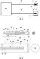
- FIG. 1-5 are accompanied of a series of numeral references which, with illustrative and non-limiting character, are hereby represented: (1) Wing (2) First detector (3) First temperature sensor (4) First housing (5) Second detector (6) Second temperature sensor (7) Second housing (8) First optic fibre detector (9) Second optic fibre detector (10) Electro-optic module (11) First optical fibre core (12) First optical sensor (13) First glass cladding (14) First protective coating (15) First sealed capillary (16) Closure cap (17) Connecting element (18) Second optical fibre core (19) Second optical sensor (20) Second glass cladding (21) Second protective coating (22) Second capillary sealed (23) Leading edge of the body (24) Inner volume behind the leading edge (25) Sensor probe
- a main object of the invention is related to a system for detecting the ice formation and accretion on a body 1, preferably suitable for determining the almost instantaneous freezing of drops of supercooled water when destabilized by, for example, impacting into the body 1.
- said ice formation and accretion detection system comprises:
- a first detection volume V1 is formed between the first temperature sensor 3 and the first housing 4, and a second detection volume V2, which is larger than volume V1, is formed between the second temperature sensor 6 and the second housing 7.
- the first and second detectors 2, 5 have different thermal inertias and hence they have different responses to temperature gradients. These different responses to temperature gradients are important to determine the formation of ice on a body 1, as will be detailed later.
- the first and second temperature sensors 3, 6 may include, but are not limited to, optical sensors such as optic fibre sensors.
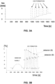
- FIG. 2 illustrates a more detailed view of an ice formation and accretion detection system according to the invention.
- This system comprises:
- the electro-optic module 10 is configured in such a way that it generates an optical signal through the first and second optic fibre detectors 8, 9 and receives said optical signals filtered by the optic fibre detectors 8, 9 to subsequently analyze and transmit measurements made on said optical signals.
- the first optic fibre detector 8 comprises:
- the first glass cladding 13 comprises:
- the first detector 8 comprises a first sealed capillary 15 comprising at least one closure cap 16 and a connecting element 17 between the first protective coating 14 and the first sealed capillary 15.
- the first sealed capillary 15 is disposed around the first glass cladding 13 at least along the first portion L1 of the first glass cladding 13.
- said first sealed capillary 15, has a second inner diameter D2 greater than the first outer diameter D1.
- the connecting element 17 may comprise a probe, an adhesive or a combination of both.
- the second optical fibre detector 9 comprises in turn:
- the thermal inertia of the first optic fibre detector 8 is lower than the thermal inertia of the second optic fibre detector 9.
- the first optic fibre detector 8 is able to detect temperature variations faster than the second optic fibre detector 9. Therefore, when an optical signal generated by the electro-optic module 10 reaches the first and second optical sensors 12, 19, these optical sensors 12, 19 will reflect part of said optical signal as a function of the temperature of said first and second optical sensors 12, 19. In this way, the filtered optical signals arriving at the electro-optic module 10 will be different as long as the temperature of said first and second optical sensors 12, 19 is different. In this way, by analyzing said filtered optical signals, the electro-optic module 10 is able to calculate the temperature at the position where the first and second optical sensors 12, 19 are located.
- the first and/or the second optical fibre cores 11, 18 comprise an external diameter between 6 and 10 micrometers.
- the first outer diameter D1 and the third outer diameter D3 are comprised between 0.006 and 0.125 mm.
- the second inner diameter D2 is comprised between 0.13 and 0.25 mm.
- the fourth inner diameter D4 is comprised between 0.5 and 1.0 mm.
- the first capillary 15 comprises a fifth outer diameter D5 comprised between 0.25 and 0.5 mm and the second capillary 22 comprises a sixth outer diameter D6 comprised between 2 and 3 mm.
- the first and second optical sensors 12, 19 have a length comprised between 2 and 20 mm.
- the first portion L1 of the first glass cladding 13 comprises a length between 2 and 20 mm.
- the third portion L3 of the first glass cladding 13 comprises a length between 20 and 50 mm.
- the first sealed capillary 15 is extended along a length comprised between 30 and 60 mm.
- the first protective coating 14 wraps the first glass cladding 13 along the second portion L2 and along the third portion L3.
- said first and / or second optical sensors 12, 19 are Fibre Bragg Gratings, also called FBG or long period fibre gratings, also called LPG.
- the first and/or the second sealed capillary 15, 22 comprise one of the following types of materials: metal, glass or polymer. Even more preferably, said first and second sealed capillaries 15, 22 are made of a thermally conductive material. In this way, the first and second sensors 12, 19 better capture the temperature of the environment.
- Another object of the invention is disclosed below, which relates to a method for detecting the ice formation and accretion on a body 1.
- Said method includes the use of the system for detecting the formation of ice in a body 1, as well as performing the following steps:
- the calculation of the derivative of the temperature with respect to time allows the estimation of the behaviour of the ice layer, and more particularly:
- this last feature is very important for the pilot, since they need to escape from the icing cloud when severe icing starts.
- the exact information about the ending of the ice accretion gives them the information so that they can stop escaping from the icing condition.
- a measure for the accretion time is the time when the sensor couple shows an increment in temperature with respect to the temperature before the ice accretion.
- a measure for the ice thickness is also the decrement of the temperature signal that is becoming weaker because of the ice layer growth.
- this method is able to detect the ice formation due to the freezing of drops of supercooled water.
- the water can be liquid at temperatures substantially below its theoretical temperature of pure water phase change, around 0° C at atmospheric pressure. Under these conditions, it is said that the water is supercooled.
- a disturbance of said drop such as the impact of said supercooled drop of water on a body 1, causes its almost instantaneous freezing, in the order of milliseconds, as well as an exothermic peak due to the release of enthalpy.
- the ice formed is around the freezing temperature of the water, around 0° C at atmospheric pressure.
- the first optical fibre detector 8 detects quickly said temperature increase, as shown in the segments BC, FG, JK, NO or RS in continuous line of Figure 3B
- the second optic fibre detector 9 due to its greater thermal inertia, due to its protected location from the air stream and due that the energy released by the water drop is substantially lower than the energy contained in the air stream
- the second optic fibre detector 9 detects a lower temperature increase, as shown in the segments in discontinuous line BC', FG', JK ', NO' or RS' of Figure 3B .
- the electro-optic module 10 measures a temperature difference between the first and second optic fibre detectors 8, 9, as shown in Figure 3C , it sends an alarm signal of the start of the ice formation on the body 1. Subsequently, during the accretion of ice on the body 1, the first detector 8 slowly decreases the temperature detected due to the increase of the ice layer on the body 1, as shown in the respective segments CD, GH, KL, OP and ST of Figure 3C .
- the second optic fibre detector 9 slowly increases the temperature it senses due to the increase of the ice layer on the body 1, as shown in the respective segments CD ', GH ', KL', OP 'and ST' of Figure 3B .
- this layer of ice depending on its thickness, quickly acquires a temperature substantially lower than its freezing point, because the environment temperature is substantially lower than the water freezing temperature.
- both detectors 8, 9 respond substantially in the same way, performing the same simultaneous temperature measurements, as shown in segments EF, IJ, MN and QR of Figure 3B and 3C .
- the first and second optic fibre detectors 8, 9 measure almost simultaneously the same temperature increase, as shown in Figure 3B . This is because the warm air bubbles contain more thermal energy and transfer this energy faster to the body 1. In this way, false alarms when the body 1 is traversed by warm air bubbles are avoided.
- the system is prepared to detect other phase changes of water and/or other substances.
- a person skilled in the art would adjust the volume difference between the first and second detectors 2, 5, their position with respect to the body 1 or even employ some temperature sensor technology different from that based on optical fibre.
- a third object of the invention is related to the use of the system for detecting the ice formation and accretion on a body 1 in the aeronautical sector using the method explained.
- the system is installed on a part of an aircraft chosen from among the following ones: the fuselage, the wings and / or at any entrance to an engine of the aircraft.
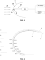
- FIG. 4 shows a preferred embodiment of the use of the present system in a circular sensor probe 25 where ice formation is to be detected.
- This probe 25 has a leading edge 23 intended to receive an air stream in a direction d1 and an inner volume 24.
- both first and second detectors 8, 9 are located inside the volume 24.
- the first detector 8 is located in contact with the leading edge 23 of the probe 25 and the second detector 9 is located downstream the first detector 8.
- the detection system can be applied to different bodies without the need to modify them in order to introduce the optic fibre detectors 8, 9.
- FIG. 5 shows a similar embodiment, but in this case, in the wing 1 of an aircraft.
- This wing 1 comprises a leading edge 23 where an air stream impinges in a direction d1.
- the wing comprises an inner volume 24.
- the first detector 8 is located in contact with the leading edge 23 of the wing 1, but outside the inner volume 24.
- the second detector 9 is located inside the volume 24, downstream the first detector 8.
- Both optic fibre detectors 8, 9 are connected to the electro-optic module 10, which transfers the measurements and alerts to a pilot of the aircraft in order to, if necessary, activate anti-icing systems.
- the electro-optic module 10 transfers the measurements and alerts to a pilot of the aircraft in order to, if necessary, activate anti-icing systems.
- a temperature difference of several degrees between the first and the second optic fibre detector 8, 9 is detected, and therefore the system will generate an alarm signal.
- both optic fibre detectors 8, 9 will detect a substantially similar temperature, avoiding possible false alarms by the system.
- this ice detection system is used in the fuselage of an aircraft, in a blade of a wind turbine or in electric transport wires.
- FIG. 6 shows another preferred embodiment of the invention.
- the first detector 8 is also located in contact with the leading edge 23 of the wing 1, but outside the inner volume 24.
- the second detector 9 is also located inside the volume 24, downstream the first detector 8.
- the first detector 8 is arranged along the leading edge 23, covering it completely, and comprises a plurality of sensors 12.1, 12.2, 12.3, 12.4, 12.5. These sensors are also distributed along the leading edge, each one being located at different chord line values of the aerodynamic surface.
- Each one of the sensors of the first detector has a counterpart in the second detector 9, where each sensor 19.1, 19.2, 19.3, 19.4, 19.5 is associated to one of the sensors of the first detector.
- the optical fibre sensors in the nose tip (12.4, 12.5 and the corresponding inner sensors 19.4 and 19.5) will detect it, whilst the other sensors along the chord will not detect any ice accretion. If super large droplets form the ice, all the sensors along the chord (12.1 to 12.5 and 19.1 to 19.5) will detect the ice formation.
- the sensors of the first detector (12.1 to 12.5) will be in more direct contact with the air stream and the ice accretion and will react much faster than the sensors of the second detector (19.1 to 19.5), which are shielded by the wing 1 itself and a tubing where they are inside.
- These sensors can be installed in one or in several positions of the wing or control surface structure to have redundancy in the monitoring of ice events.
- the electro-optic module 10 comprises an optical interrogator.
- the formation and accretion of ice on a body 1 is allowed to be measured quickly and accurately.
- Another advantage of said detection system is that it is based on optical measurements so it does not electromagnetically interfere with the environment and is not interfered by it.
Landscapes
- Engineering & Computer Science (AREA)
- Physics & Mathematics (AREA)
- General Physics & Mathematics (AREA)
- Aviation & Aerospace Engineering (AREA)
- Sustainable Energy (AREA)
- Sustainable Development (AREA)
- Life Sciences & Earth Sciences (AREA)
- Chemical & Material Sciences (AREA)
- Combustion & Propulsion (AREA)
- Mechanical Engineering (AREA)
- General Engineering & Computer Science (AREA)
- Measuring Temperature Or Quantity Of Heat (AREA)
- Testing Or Calibration Of Command Recording Devices (AREA)
- Investigating Or Analyzing Materials By The Use Of Electric Means (AREA)
- Investigating Or Analyzing Materials Using Thermal Means (AREA)
Claims (15)
- Système pour détecter la formation de glace sur un corps (1) comprenant au moins :un premier détecteur (2, 8) comprenant un premier capteur de température (3, 12) ;un second détecteur (5, 9) comprenant un second capteur de température (6, 19) ; etun module électro-optique (10) configuré pour générer des signaux de mesure d'entrée dans les premier (2, 8) et second (5, 9) détecteurs, pour recevoir des signaux de mesure des premier (2, 8) et second (5, 9) détecteurs et pour traiter et transmettre des mesures ;le système étant caractérisé en ce que :le premier détecteur (2, 8) comprend un premier boîtier (4, 15) entourant le premier capteur de température (3, 12) définissant un premier volume de détection (V1) formé entre le premier capteur de température (3, 12) et le premier boîtier (4, 15), le premier volume de détection (V1) étant rempli par un fluide, tel que l'air ;le second détecteur (5, 9) comprend un second boîtier (7, 22) entourant le second capteur de température (6, 19) définissant un second volume de détection (V2) formé entre le second capteur de température (6, 19) et le second boîtier (7, 22), le second volume de détection (V2) étant rempli par un fluide, tel que l'air ; et en ce quele premier détecteur (2, 8) et le second détecteur (5, 9) ont des inerties thermiques différentes.
- Système selon la revendication 1, dans lequel les différentes inerties thermiques sont obtenues par le fait que le second volume de détection (V2) est supérieur au premier volume de détection (V1).
- Système selon l'une quelconque des revendications précédentes, dans lequel au moins un premier détecteur est un premier détecteur à fibre optique (8) dans lequel :le premier détecteur à fibre optique (8) comprend un premier coeur de fibre optique (11) ;le premier capteur de température est disposé dans le premier coeur de fibre optique (11), le premier capteur de température étant un premier capteur optique (12) ;le premier détecteur à fibre optique (8) comprend une première gaine de verre (13) ayant un premier diamètre extérieur, la première gaine de verre (13) étant disposée autour du premier coeur de fibre optique (11) de telle manière qu'une première partie de la première gaine de verre (13) entoure le premier capteur optique (12) ;le premier boîtier est un premier capillaire scellé (15) ayant un second diamètre intérieur, le premier capillaire scellé (15) étant disposé au moins autour de la première partie de la première gaine de verre (13), dans lequel le second diamètre intérieur est supérieur au premier diamètre extérieur, et le premier volume de détection (V1) correspond au volume entre le premier diamètre extérieur et le second diamètre intérieur ;dans lequel au moins un second détecteur est un second détecteur à fibres optiques (9) dans lequel :le second détecteur à fibre optique (9) comprend un second coeur de fibre optique (18) ;le second capteur de température est disposé dans le second coeur de fibre optique (18), le second capteur de température étant un second capteur optique (19) ;le second détecteur à fibres optiques (9) comprend une seconde gaine de verre (20) ayant un troisième diamètre extérieur, la seconde gaine de verre (20) étant disposée autour du second coeur de fibre optique (18) ;le second boîtier est un second capillaire scellé (22), ce second capillaire scellé (22) ayant un quatrième diamètre intérieur, le second capillaire scellé (22) étant disposé autour de la seconde gaine de verre (20), le quatrième diamètre intérieur étant supérieur au troisième diamètre extérieur et le second volume de détection (V2) correspond au volume entre le troisième diamètre extérieur et le quatrième diamètre intérieur,dans lequel la différence entre le quatrième diamètre intérieur et le troisième diamètre extérieur est supérieure à la différence entre le deuxième diamètre intérieur et le premier diamètre extérieur ; et dans lequel le module électro-optique (10) est configuré pour générer des entrées lumineuses et pour recevoir des mesures optiques des premier et deuxième détecteurs à fibre optique (8, 9) et également configuré pour traiter et transmettre les mesures optiques.
- Système selon la revendication 3, dans lequel le premier détecteur et le second détecteur comprennent une pluralité de capteurs à fibre optique (12, 19), chaque capteur à fibre optique comprenant un réseau de Bragg à fibre ou un réseau de fibre à longue période.
- Système selon l'une quelconque des revendications 3 ou 4, dans lequel le premier diamètre extérieur et le troisième diamètre extérieur sont compris entre 0,006 et 0,1265 mm, dans lequel le deuxième diamètre intérieur est compris entre 0,13 et 0,25 mm et dans lequel le quatrième diamètre intérieur est compris entre 0,5 et 1,0 mm,dans lequel le premier capillaire (15) d'au moins un premier détecteur à fibre optique (8) comprend un cinquième diamètre extérieur compris entre 0,25 et 0,5 mm et dans lequel le deuxième capillaire (22) scellé d'au moins un second détecteur à fibre optique (9) comprend un sixième diamètre extérieur compris entre 2 et 3 mm, etdans lequel les premier et second capteurs optiques (12, 19) ont une longueur comprise entre 2 et 20 mm ; etdans lequel le premier capillaire scellé (15) comprend un matériau métallique ou polymère et le second capillaire scellé (22) comprend du verre, un polymère ou un métal.
- Système selon l'une quelconque des revendications 2 à 5, dans lequel au moins un premier détecteur à fibre optique (8) comprend :un premier revêtement protecteur (14) autour d'une deuxième partie de la première gaine de verre (13), de telle sorte que la deuxième partie de la première gaine de verre (13) est revêtue par le premier revêtement protecteur (14) et une troisième partie de la première gaine de verre (13) n'est pas revêtue, la première partie étant sensiblement au milieu de la troisième partie et le premier capillaire scellé (15) étant autour de la troisième partie,un élément de liaison (17) entre le premier revêtement protecteur (14) et le premier capillaire scellé (15) ;et dans lequel au moins un second détecteur à fibre optique (9) comprend un second revêtement protecteur (21) autour de la seconde gaine de verre (20).
- Système selon la revendication précédente, dans lequel la troisième partie s'étend sur une longueur comprise entre 20 et 50 mm, et
le premier capillaire scellé (15) s'étend sur une longueur comprise entre 30 et 60 mm. - Système selon l'une quelconque des revendications 6 ou 7, dans lequel l'élément de liaison (17) entre le premier revêtement protecteur (14) et le premier capillaire scellé (15) d'au moins un premier détecteur à fibre optique (8) comprend une sonde ou un adhésif, ou une combinaison des deux.
- Système selon l'une quelconque des revendications précédentes comprenant en outre une surface aérodynamique (1, 25) avec un bord d'attaque (23) destiné à recevoir un flux d'air et un volume (24) en aval du bord d'attaque (23), dans lequel le premier détecteur (8) est situé au contact du bord d'attaque (23) de la surface aérodynamique (1, 25) et le second détecteur (9) est situé dans le volume (24), en aval du premier détecteur (8).
- Système selon la revendication 9, dans lequel le premier détecteur est disposé de manière à couvrir au moins une partie du bord d'attaque et comprend une pluralité de capteurs (12.1, 12.2, 12.3, 12.4, 12.5), au moins deux capteurs étant situés à des valeurs de corde différentes de la surface aérodynamique.
- Procédé de détection de la formation de glace sur un corps (1) par un système selon les revendications 1 à 10, le procédé étant caractérisé en ce qu'il comprend les étapes suivantes :générer un signal d'entrée dans les premier et second détecteurs (2, 5) ;générer un signal de sortie par les premier et second détecteurs de température (3, 6);recevoir le signal de sortie dans le module électro-optique (10) ;traiter le signal de sortie reçu et calculer une différence de température ;générer un signal d'avertissement si la différence de température est supérieure à un seuil de température prédéterminé.
- Procédé selon la revendication 11, comprenant les étapes suivantes :injecter un faisceau lumineux dans chacun des premier et second détecteurs (8, 9), dans lequel les détecteurs sont des détecteurs à fibre optique ;filtrer respectivement les faisceaux lumineux dans les au moins premier et second capteurs optiques (12, 19) en fonction de la température du capteur optique respectif (12, 19) ;recevoir les faisceaux lumineux filtrés respectifs dans le module électro-optique (10) ;traiter les faisceaux lumineux reçus et calculer une différence de température ;générer un signal d'avertissement si la différence de température est supérieure à un seuil de température prédéterminé.
- Procédé selon la revendication 12, dans lequel avant l'étape d'injection d'un faisceau lumineux, le procédé comprend en outre les étapes consistant à :fournir un corps (1) où la formation de glace doit être détectée, le corps (1) comprenant une surface extérieure (23) destinée à recevoir un flux d'air et un volume (24) en aval de cette surface extérieure (23) disposé pour être protégé du flux d'air ;placer au moins un premier détecteur à fibres optiques (8) en contact avec la surface extérieure (23) du corps (1) et placer au moins un deuxième détecteur à fibres optiques (9) dans le volume (24) derrière la surface extérieure (23).
- Procédé selon l'une quelconque des revendications 11 à 13, dans lequell'étape de traitement du signal de sortie reçu comprend en outre le calcul de la dérivée de la température par rapport au temps, etl'étape de génération d'un signal d'avertissement comprend la génération de l'un d'un groupe prédéterminé de signaux d'avertissement, en fonction du résultat de la dérivée de la température par rapport au temps.
- Utilisation du système selon l'une quelconque des revendications 1 à 10 ou d'un procédé selon l'une quelconque des revendications 11 à 14 pour détecter la glace dans l'un quelconque des corps suivants : une partie d'un aéronef ou d'une éolienne ou une ligne de transmission d'énergie électrique.
Applications Claiming Priority (2)
| Application Number | Priority Date | Filing Date | Title |
|---|---|---|---|
| EP18382649.4A EP3620379A1 (fr) | 2018-09-10 | 2018-09-10 | Système et procédé pour détecter la formation de glace sur un corps |
| PCT/EP2019/074091 WO2020053202A1 (fr) | 2018-09-10 | 2019-09-10 | Système et procédé de détection de formation de glace sur un corps |
Publications (3)
| Publication Number | Publication Date |
|---|---|
| EP3849906A1 EP3849906A1 (fr) | 2021-07-21 |
| EP3849906B1 true EP3849906B1 (fr) | 2023-06-07 |
| EP3849906C0 EP3849906C0 (fr) | 2023-06-07 |
Family
ID=63762433
Family Applications (2)
| Application Number | Title | Priority Date | Filing Date |
|---|---|---|---|
| EP18382649.4A Withdrawn EP3620379A1 (fr) | 2018-09-10 | 2018-09-10 | Système et procédé pour détecter la formation de glace sur un corps |
| EP19763012.2A Active EP3849906B1 (fr) | 2018-09-10 | 2019-09-10 | Système et procédé pour détecter la formation de glace sur un corps |
Family Applications Before (1)
| Application Number | Title | Priority Date | Filing Date |
|---|---|---|---|
| EP18382649.4A Withdrawn EP3620379A1 (fr) | 2018-09-10 | 2018-09-10 | Système et procédé pour détecter la formation de glace sur un corps |
Country Status (5)
| Country | Link |
|---|---|
| US (1) | US11794909B2 (fr) |
| EP (2) | EP3620379A1 (fr) |
| ES (1) | ES2950769T3 (fr) |
| PL (1) | PL3849906T3 (fr) |
| WO (1) | WO2020053202A1 (fr) |
Families Citing this family (8)
| Publication number | Priority date | Publication date | Assignee | Title |
|---|---|---|---|---|
| CN113155315B (zh) * | 2021-04-25 | 2022-12-16 | 中国极地研究中心 | 一种温度监测装置 |
| CN113325270B (zh) * | 2021-06-03 | 2022-08-30 | 广东电网有限责任公司 | 一种光缆输电线路监测方法及装置 |
| CN114132512B (zh) * | 2022-02-07 | 2022-04-29 | 中国空气动力研究与发展中心低速空气动力研究所 | 一种光纤结冰传感器探头及调节方法 |
| CN114180072B (zh) * | 2022-02-16 | 2022-04-12 | 中国空气动力研究与发展中心低速空气动力研究所 | 一种结冰厚度探测方法 |
| US20240017840A1 (en) * | 2022-07-15 | 2024-01-18 | Rosemount Aerospace Inc. | Temperature-based suppression of spurious ice signals |
| CN115416854B (zh) * | 2022-11-07 | 2023-01-24 | 中国空气动力研究与发展中心低速空气动力研究所 | 一种基于温度测量的结冰探测装置及结冰探测方法 |
| CN116331495A (zh) * | 2023-05-31 | 2023-06-27 | 中国航空工业集团公司沈阳空气动力研究所 | 一种管路式过冷大水滴探测器轮廓结构 |
| CN116674756A (zh) * | 2023-07-11 | 2023-09-01 | 电子科技大学 | 一种基于分布式光纤的机翼积冰探测及融冰装置 |
Family Cites Families (16)
| Publication number | Priority date | Publication date | Assignee | Title |
|---|---|---|---|---|
| US2766619A (en) * | 1953-06-26 | 1956-10-16 | Tribus Myron | Ice detecting apparatus |
| US4210021A (en) | 1978-07-06 | 1980-07-01 | Bantsekin Viktor I | Method and device for detecting icing of objects found in air flow |
| US4882574A (en) * | 1988-06-20 | 1989-11-21 | Boris Khurgin | Two-resistor ice detector |
| AU3111900A (en) * | 1998-12-04 | 2000-06-19 | Cidra Corporation | Pressure-isolated bragg grating temperature sensor |
| WO2005017477A1 (fr) * | 2002-11-21 | 2005-02-24 | Trustees Of Boston University | Capteur de temperature a fibre optique |
| US7096683B2 (en) * | 2003-09-12 | 2006-08-29 | Ford Global Technologies, Llc | Vehicle cooling system |
| GB2407377B (en) | 2003-10-16 | 2006-04-19 | Kidde Ip Holdings Ltd | Fibre bragg grating sensors |
| JP2010502518A (ja) * | 2007-11-30 | 2010-01-28 | ビ−エイイ− システムズ パブリック リミテッド カンパニ− | 温度の監視に関する改良 |
| US8192069B2 (en) * | 2008-05-12 | 2012-06-05 | Koopmans Richard J | Water supply mixing process |
| US8517601B2 (en) * | 2010-09-10 | 2013-08-27 | Ultra Electronics Limited | Ice detection system and method |
| WO2016164165A1 (fr) * | 2015-04-09 | 2016-10-13 | True Manufacturing Co., Inc. | Procédés et appareils permettant de commander le cycle de récolte d'une machine à glaçons à l'aide d'un capteur de récolte et d'un capteur de température |
| US10260789B2 (en) * | 2016-04-13 | 2019-04-16 | Whirlpool Corporation | Ice making assembly with twist ice tray and directional cooling |
| US10173498B2 (en) * | 2016-06-21 | 2019-01-08 | Nissan North America, Inc. | Vehicle air conditioning system |
| GB2554062A (en) * | 2016-08-22 | 2018-03-28 | Norwegian Univ Of Science And Technology | Icing control system |
| US10457404B2 (en) * | 2017-01-31 | 2019-10-29 | Wan Tony Chee | Carbon nanotube anti-icing and de-icing means for aircraft |
| US11510576B2 (en) * | 2017-04-27 | 2022-11-29 | Medtronic Cryocath Lp | Treatment device having multifunctional sensing elements and method of use |
-
2018
- 2018-09-10 EP EP18382649.4A patent/EP3620379A1/fr not_active Withdrawn
-
2019
- 2019-09-10 EP EP19763012.2A patent/EP3849906B1/fr active Active
- 2019-09-10 PL PL19763012.2T patent/PL3849906T3/pl unknown
- 2019-09-10 WO PCT/EP2019/074091 patent/WO2020053202A1/fr not_active Ceased
- 2019-09-10 US US17/274,269 patent/US11794909B2/en active Active
- 2019-09-10 ES ES19763012T patent/ES2950769T3/es active Active
Also Published As
| Publication number | Publication date |
|---|---|
| US11794909B2 (en) | 2023-10-24 |
| US20210316869A1 (en) | 2021-10-14 |
| EP3849906C0 (fr) | 2023-06-07 |
| PL3849906T3 (pl) | 2023-11-06 |
| ES2950769T3 (es) | 2023-10-13 |
| BR112021004166A2 (pt) | 2021-05-25 |
| CA3110541A1 (fr) | 2020-03-19 |
| EP3620379A1 (fr) | 2020-03-11 |
| EP3849906A1 (fr) | 2021-07-21 |
| WO2020053202A1 (fr) | 2020-03-19 |
Similar Documents
| Publication | Publication Date | Title |
|---|---|---|
| EP3849906B1 (fr) | Système et procédé pour détecter la formation de glace sur un corps | |
| RU2534493C2 (ru) | Система и способ применения датчика обледенения | |
| EP2800690B1 (fr) | Système de détection d'une condition de givrage à grosses gouttes surfondues | |
| US8060334B1 (en) | Aircraft pitot-static tube with ice detection | |
| CA3052014C (fr) | Systemes de detection de givrage pour aeronef et methodes connexes | |
| CA2784022C (fr) | Systeme de detecteur | |
| EP3739342B1 (fr) | Surveillance pronostique de capteurs complémentaires de système de données d'air | |
| US6430996B1 (en) | Probe and integrated ice detection and air data system | |
| CN113532304B (zh) | 基于准分布式光纤光栅的机翼蒙皮结构健康状态监测方法 | |
| EP3567369B1 (fr) | Procédé de fabrication d'une sonde de capteur de taux de givrage d'oscillateur magnétostrictif | |
| GB2475553A (en) | A sensor arrangement for determining the rate of ice formation | |
| US4965572A (en) | Method for producing a warning of the existence of low-level wind shear and aircraftborne system for performing same | |
| Gonzalez et al. | Fiber Bragg grating sensors ice detection: Methodologies and performance | |
| CA3110541C (fr) | Systeme et procede de detection de formation de glace sur un corps | |
| US6134959A (en) | Method for detecting flow bifurcation during sonic flow conditions | |
| US6380535B1 (en) | Optical tuft for flow separation detection | |
| EP3456637A1 (fr) | Systèmes et procédés permettant de détecter des impacts sur des surfaces de véhicule | |
| Del Val et al. | Flight tests results of a fiber Bragg gratings based ice sensor | |
| US20230304793A1 (en) | Device for detecting frosting intensity for an aircraft in flight | |
| BR112021004166B1 (pt) | Sistema e método para detectar formação de gelo em um corpo | |
| RU2341414C1 (ru) | Способ обнаружения обледенения несущего винта вертолета | |
| Ratvasky et al. | Air data probe anomalies in flight through measured high ice water content conditions | |
| Davison et al. | NRC Particle Detection Probe: Results and Analysis from Ground and Flight Tests | |
| Sachs et al. | Flight Testing the Indirect Ice Detection System in the Horizon 2020 Project SENS4ICE | |
| González del Val et al. | Fiber Bragg Grating Sensors ice detection: methodologies and performance |
Legal Events
| Date | Code | Title | Description |
|---|---|---|---|
| STAA | Information on the status of an ep patent application or granted ep patent |
Free format text: STATUS: UNKNOWN |
|
| STAA | Information on the status of an ep patent application or granted ep patent |
Free format text: STATUS: THE INTERNATIONAL PUBLICATION HAS BEEN MADE |
|
| PUAI | Public reference made under article 153(3) epc to a published international application that has entered the european phase |
Free format text: ORIGINAL CODE: 0009012 |
|
| STAA | Information on the status of an ep patent application or granted ep patent |
Free format text: STATUS: REQUEST FOR EXAMINATION WAS MADE |
|
| 17P | Request for examination filed |
Effective date: 20210407 |
|
| AK | Designated contracting states |
Kind code of ref document: A1 Designated state(s): AL AT BE BG CH CY CZ DE DK EE ES FI FR GB GR HR HU IE IS IT LI LT LU LV MC MK MT NL NO PL PT RO RS SE SI SK SM TR |
|
| DAV | Request for validation of the european patent (deleted) | ||
| DAX | Request for extension of the european patent (deleted) | ||
| RIC1 | Information provided on ipc code assigned before grant |
Ipc: G01K 11/3206 20210101ALI20220304BHEP Ipc: G01D 5/353 20060101ALI20220304BHEP Ipc: B64D 15/20 20060101AFI20220304BHEP |
|
| GRAP | Despatch of communication of intention to grant a patent |
Free format text: ORIGINAL CODE: EPIDOSNIGR1 |
|
| STAA | Information on the status of an ep patent application or granted ep patent |
Free format text: STATUS: GRANT OF PATENT IS INTENDED |
|
| INTG | Intention to grant announced |
Effective date: 20220902 |
|
| GRAS | Grant fee paid |
Free format text: ORIGINAL CODE: EPIDOSNIGR3 |
|
| RAP3 | Party data changed (applicant data changed or rights of an application transferred) |
Owner name: INSTITUTO NACIONAL DE TECNICA AEROESPACIAL "ESTEBAN TERRADAS" |
|
| GRAA | (expected) grant |
Free format text: ORIGINAL CODE: 0009210 |
|
| STAA | Information on the status of an ep patent application or granted ep patent |
Free format text: STATUS: THE PATENT HAS BEEN GRANTED |
|
| AK | Designated contracting states |
Kind code of ref document: B1 Designated state(s): AL AT BE BG CH CY CZ DE DK EE ES FI FR GB GR HR HU IE IS IT LI LT LU LV MC MK MT NL NO PL PT RO RS SE SI SK SM TR |
|
| REG | Reference to a national code |
Ref country code: GB Ref legal event code: FG4D |
|
| REG | Reference to a national code |
Ref country code: CH Ref legal event code: EP Ref country code: AT Ref legal event code: REF Ref document number: 1574294 Country of ref document: AT Kind code of ref document: T Effective date: 20230615 Ref country code: DE Ref legal event code: R096 Ref document number: 602019030383 Country of ref document: DE |
|
| REG | Reference to a national code |
Ref country code: NO Ref legal event code: T2 Effective date: 20230607 |
|
| U01 | Request for unitary effect filed |
Effective date: 20230704 |
|
| U07 | Unitary effect registered |
Designated state(s): AT BE BG DE DK EE FI FR IT LT LU LV MT NL PT SE SI Effective date: 20230714 |
|
| U20 | Renewal fee for the european patent with unitary effect paid |
Year of fee payment: 5 Effective date: 20230718 |
|
| REG | Reference to a national code |
Ref country code: LT Ref legal event code: MG9D |
|
| REG | Reference to a national code |
Ref country code: ES Ref legal event code: FG2A Ref document number: 2950769 Country of ref document: ES Kind code of ref document: T3 Effective date: 20231013 |
|
| PG25 | Lapsed in a contracting state [announced via postgrant information from national office to epo] |
Ref country code: RS Free format text: LAPSE BECAUSE OF FAILURE TO SUBMIT A TRANSLATION OF THE DESCRIPTION OR TO PAY THE FEE WITHIN THE PRESCRIBED TIME-LIMIT Effective date: 20230607 Ref country code: HR Free format text: LAPSE BECAUSE OF FAILURE TO SUBMIT A TRANSLATION OF THE DESCRIPTION OR TO PAY THE FEE WITHIN THE PRESCRIBED TIME-LIMIT Effective date: 20230607 Ref country code: GR Free format text: LAPSE BECAUSE OF FAILURE TO SUBMIT A TRANSLATION OF THE DESCRIPTION OR TO PAY THE FEE WITHIN THE PRESCRIBED TIME-LIMIT Effective date: 20230908 |
|
| PG25 | Lapsed in a contracting state [announced via postgrant information from national office to epo] |
Ref country code: SK Free format text: LAPSE BECAUSE OF FAILURE TO SUBMIT A TRANSLATION OF THE DESCRIPTION OR TO PAY THE FEE WITHIN THE PRESCRIBED TIME-LIMIT Effective date: 20230607 |
|
| PG25 | Lapsed in a contracting state [announced via postgrant information from national office to epo] |
Ref country code: IS Free format text: LAPSE BECAUSE OF FAILURE TO SUBMIT A TRANSLATION OF THE DESCRIPTION OR TO PAY THE FEE WITHIN THE PRESCRIBED TIME-LIMIT Effective date: 20231007 |
|
| PG25 | Lapsed in a contracting state [announced via postgrant information from national office to epo] |
Ref country code: SM Free format text: LAPSE BECAUSE OF FAILURE TO SUBMIT A TRANSLATION OF THE DESCRIPTION OR TO PAY THE FEE WITHIN THE PRESCRIBED TIME-LIMIT Effective date: 20230607 Ref country code: SK Free format text: LAPSE BECAUSE OF FAILURE TO SUBMIT A TRANSLATION OF THE DESCRIPTION OR TO PAY THE FEE WITHIN THE PRESCRIBED TIME-LIMIT Effective date: 20230607 Ref country code: RO Free format text: LAPSE BECAUSE OF FAILURE TO SUBMIT A TRANSLATION OF THE DESCRIPTION OR TO PAY THE FEE WITHIN THE PRESCRIBED TIME-LIMIT Effective date: 20230607 Ref country code: IS Free format text: LAPSE BECAUSE OF FAILURE TO SUBMIT A TRANSLATION OF THE DESCRIPTION OR TO PAY THE FEE WITHIN THE PRESCRIBED TIME-LIMIT Effective date: 20231007 Ref country code: CZ Free format text: LAPSE BECAUSE OF FAILURE TO SUBMIT A TRANSLATION OF THE DESCRIPTION OR TO PAY THE FEE WITHIN THE PRESCRIBED TIME-LIMIT Effective date: 20230607 |
|
| REG | Reference to a national code |
Ref country code: DE Ref legal event code: R097 Ref document number: 602019030383 Country of ref document: DE |
|
| PLBE | No opposition filed within time limit |
Free format text: ORIGINAL CODE: 0009261 |
|
| STAA | Information on the status of an ep patent application or granted ep patent |
Free format text: STATUS: NO OPPOSITION FILED WITHIN TIME LIMIT |
|
| 26N | No opposition filed |
Effective date: 20240308 |
|
| GBPC | Gb: european patent ceased through non-payment of renewal fee |
Effective date: 20230910 |
|
| PG25 | Lapsed in a contracting state [announced via postgrant information from national office to epo] |
Ref country code: MC Free format text: LAPSE BECAUSE OF FAILURE TO SUBMIT A TRANSLATION OF THE DESCRIPTION OR TO PAY THE FEE WITHIN THE PRESCRIBED TIME-LIMIT Effective date: 20230607 |
|
| PG25 | Lapsed in a contracting state [announced via postgrant information from national office to epo] |
Ref country code: GB Free format text: LAPSE BECAUSE OF NON-PAYMENT OF DUE FEES Effective date: 20230910 |
|
| PG25 | Lapsed in a contracting state [announced via postgrant information from national office to epo] |
Ref country code: GB Free format text: LAPSE BECAUSE OF NON-PAYMENT OF DUE FEES Effective date: 20230910 |
|
| U20 | Renewal fee for the european patent with unitary effect paid |
Year of fee payment: 6 Effective date: 20240702 |
|
| U1N | Appointed representative for the unitary patent procedure changed after the registration of the unitary effect |
Representative=s name: TRBL INTELLECTUAL PROPERTY; ES |
|
| PG25 | Lapsed in a contracting state [announced via postgrant information from national office to epo] |
Ref country code: CY Free format text: LAPSE BECAUSE OF FAILURE TO SUBMIT A TRANSLATION OF THE DESCRIPTION OR TO PAY THE FEE WITHIN THE PRESCRIBED TIME-LIMIT; INVALID AB INITIO Effective date: 20190910 |
|
| PG25 | Lapsed in a contracting state [announced via postgrant information from national office to epo] |
Ref country code: HU Free format text: LAPSE BECAUSE OF FAILURE TO SUBMIT A TRANSLATION OF THE DESCRIPTION OR TO PAY THE FEE WITHIN THE PRESCRIBED TIME-LIMIT; INVALID AB INITIO Effective date: 20190910 |
|
| REG | Reference to a national code |
Ref country code: CH Ref legal event code: U11 Free format text: ST27 STATUS EVENT CODE: U-0-0-U10-U11 (AS PROVIDED BY THE NATIONAL OFFICE) Effective date: 20251001 |
|
| PGFP | Annual fee paid to national office [announced via postgrant information from national office to epo] |
Ref country code: NO Payment date: 20250929 Year of fee payment: 7 |
|
| PGFP | Annual fee paid to national office [announced via postgrant information from national office to epo] |
Ref country code: PL Payment date: 20250821 Year of fee payment: 7 |
|
| U20 | Renewal fee for the european patent with unitary effect paid |
Year of fee payment: 7 Effective date: 20250905 |
|
| PGFP | Annual fee paid to national office [announced via postgrant information from national office to epo] |
Ref country code: IE Payment date: 20250929 Year of fee payment: 7 |
|
| PG25 | Lapsed in a contracting state [announced via postgrant information from national office to epo] |
Ref country code: TR Free format text: LAPSE BECAUSE OF FAILURE TO SUBMIT A TRANSLATION OF THE DESCRIPTION OR TO PAY THE FEE WITHIN THE PRESCRIBED TIME-LIMIT Effective date: 20230607 |
|
| PGFP | Annual fee paid to national office [announced via postgrant information from national office to epo] |
Ref country code: CH Payment date: 20251001 Year of fee payment: 7 |
|
| PGFP | Annual fee paid to national office [announced via postgrant information from national office to epo] |
Ref country code: ES Payment date: 20251002 Year of fee payment: 7 |