EP3849914B1 - Behälter mit scharnier - Google Patents
Behälter mit scharnier Download PDFInfo
- Publication number
- EP3849914B1 EP3849914B1 EP19858810.5A EP19858810A EP3849914B1 EP 3849914 B1 EP3849914 B1 EP 3849914B1 EP 19858810 A EP19858810 A EP 19858810A EP 3849914 B1 EP3849914 B1 EP 3849914B1
- Authority
- EP
- European Patent Office
- Prior art keywords
- hinge
- container
- configuration
- projection
- relative
- Prior art date
- Legal status (The legal status is an assumption and is not a legal conclusion. Google has not performed a legal analysis and makes no representation as to the accuracy of the status listed.)
- Active
Links
Images




Classifications
-
- B—PERFORMING OPERATIONS; TRANSPORTING
- B65—CONVEYING; PACKING; STORING; HANDLING THIN OR FILAMENTARY MATERIAL
- B65D—CONTAINERS FOR STORAGE OR TRANSPORT OF ARTICLES OR MATERIALS, e.g. BAGS, BARRELS, BOTTLES, BOXES, CANS, CARTONS, CRATES, DRUMS, JARS, TANKS, HOPPERS, FORWARDING CONTAINERS; ACCESSORIES, CLOSURES, OR FITTINGS THEREFOR; PACKAGING ELEMENTS; PACKAGES
- B65D21/00—Nestable, stackable or joinable containers; Containers of variable capacity
- B65D21/08—Containers of variable capacity
- B65D21/086—Collapsible or telescopic containers
-
- A—HUMAN NECESSITIES
- A45—HAND OR TRAVELLING ARTICLES
- A45C—PURSES; LUGGAGE; HAND CARRIED BAGS
- A45C13/00—Details; Accessories
- A45C13/005—Hinges
-
- A—HUMAN NECESSITIES
- A45—HAND OR TRAVELLING ARTICLES
- A45C—PURSES; LUGGAGE; HAND CARRIED BAGS
- A45C13/00—Details; Accessories
- A45C13/005—Hinges
- A45C13/007—Hinges with spring means
-
- A—HUMAN NECESSITIES
- A45—HAND OR TRAVELLING ARTICLES
- A45C—PURSES; LUGGAGE; HAND CARRIED BAGS
- A45C3/00—Flexible luggage; Handbags
-
- A—HUMAN NECESSITIES
- A45—HAND OR TRAVELLING ARTICLES
- A45C—PURSES; LUGGAGE; HAND CARRIED BAGS
- A45C7/00—Collapsible or extensible purses, luggage, bags or the like
- A45C7/0059—Flexible luggage; Hand bags
- A45C7/0077—Flexible luggage; Hand bags collapsible to a minimal configuration, e.g. for storage purposes
-
- A—HUMAN NECESSITIES
- A45—HAND OR TRAVELLING ARTICLES
- A45C—PURSES; LUGGAGE; HAND CARRIED BAGS
- A45C7/00—Collapsible or extensible purses, luggage, bags or the like
- A45C7/0059—Flexible luggage; Hand bags
- A45C7/0095—Flexible luggage; Hand bags comprising a plurality of hinged panels to be unfolded in one plane for access purposes
-
- B—PERFORMING OPERATIONS; TRANSPORTING
- B65—CONVEYING; PACKING; STORING; HANDLING THIN OR FILAMENTARY MATERIAL
- B65D—CONTAINERS FOR STORAGE OR TRANSPORT OF ARTICLES OR MATERIALS, e.g. BAGS, BARRELS, BOTTLES, BOXES, CANS, CARTONS, CRATES, DRUMS, JARS, TANKS, HOPPERS, FORWARDING CONTAINERS; ACCESSORIES, CLOSURES, OR FITTINGS THEREFOR; PACKAGING ELEMENTS; PACKAGES
- B65D33/00—Details of, or accessories for, sacks or bags
- B65D33/007—Details of, or accessories for, sacks or bags for facilitating the separation of the two walls, e.g. walls of inequal height, tabs; for maintaining the mouth of the sack or bag open
-
- Y—GENERAL TAGGING OF NEW TECHNOLOGICAL DEVELOPMENTS; GENERAL TAGGING OF CROSS-SECTIONAL TECHNOLOGIES SPANNING OVER SEVERAL SECTIONS OF THE IPC; TECHNICAL SUBJECTS COVERED BY FORMER USPC CROSS-REFERENCE ART COLLECTIONS [XRACs] AND DIGESTS
- Y02—TECHNOLOGIES OR APPLICATIONS FOR MITIGATION OR ADAPTATION AGAINST CLIMATE CHANGE
- Y02W—CLIMATE CHANGE MITIGATION TECHNOLOGIES RELATED TO WASTEWATER TREATMENT OR WASTE MANAGEMENT
- Y02W30/00—Technologies for solid waste management
- Y02W30/50—Reuse, recycling or recovery technologies
- Y02W30/80—Packaging reuse or recycling, e.g. of multilayer packaging
Definitions
- the hinge may be a single piece. In an aspect of the present disclosure, the hinge may be more than one piece.
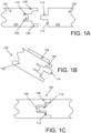
- FIGS. 1 A-1D illustrate an exemplary embodiment of a hinge according to embodiments described herein in different configurations.
- Exemplary embodiments of the hinge may be incorporated into a container for holding and retaining objects.
- the container may be flexible, and the hinge may be used to retain the container, or a portion thereof, in at desired position.
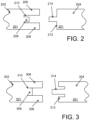
- the second portion 104 includes a body in which one or more projections extend from a terminal end thereof. As illustrated, one projection is provided. However, any combination of projections may be used.
- the terminal end of the second portion 104 includes a surface 112 at a terminal end of the body in which projection 114 extends therefrom.
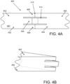
- FIGS 4A-4B illustrate an exemplary hinge 400 according to embodiments described herein. Similar to FIGS. 1-3 , the exemplary hinge includes a retention interface to retaining the hinge in an expanded configuration.
- the exterior projections 406 extend across and are integral between the first portion 402 and second portion 404, such that the hinge makes a unitary body 401.
- the projections 406 include an axis of rotation 416 or a pivot line in which the first portion 402 moves relative to the second portion 404.
- the axis of rotation 416 may be defined by a living hinge, indentation, crease, bend, or other coupling between the projections 406 of the respective first portion 402 and second portion 404.
- the projections move past each other
- the first portion 402 includes a first side 452 and a second side (not shown) and the second portion 404 includes a first side 454 and a second side 456.
- the first and second sides may be generally planar, flat, parallel, and/or opposite sides of each portion.
- the first sides 452, 454 are on the same side of the hinge and the second sides 456 are on the same side of the hinge and opposite the first sides.
- the fist sides are on an interior of the hinge and positioned adjacent and proximate each other, while the second sides of the portions are on an exterior side of the hinge.
- the container may include an opening to permit access to an interior of the container.
- the opening may be defined by an edge.
- the edge of the opening is the perimeter of the open side of the container.
- Positioned at or adjacent the edge of the opening may be one or more hinges according to embodiments described herein.
- the edge may include one or more boarders that define a passage.
- the one or more hinges may be positioned within the one or more passages.
- a terminal end of the container proximate the opening includes a folded over section that creates an internal passage.
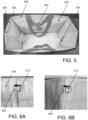
- a hinge according to embodiments described herein are positioned within the passage 526 on opposing sides of the container on opposite sides of the opening.
- the intermediate sides between the opposing sides of the container may include additional hinges, or may include a reinforcement to retain a desired shape of the side within another passage 528.
- the passages 526, 528 may traverse and entire length of a respective side or may extend a portion of the length of a side.
- the container and/or hinge may include a biased configuration toward the collapsed or expanded configuration.
- the hinge may include a remembered state in which the hinge is at least partially bent and not in a fully extended, or approximately linear configuration.
- the remembered state may impose a biasing force against the hinge in the extended configuration toward the collapsed configuration.
- the biasing force may provide frictional engagement between the retention interfaces.
- the biased configuration may also be created by a flexible and/or elastic component or band.
- FIGS. 6A-6B illustrate a partial view of the bag of FIG. 5 at the hinge.
- the retention interface of an exemplary hinge include extensions 608, 614.
- the hinge is within a passage 626 of the container.
- the passage may include an opening such that the retention interface is visible to a user.
- the opening may permit a user to visually inspect the position of the retention interface and/or any additional locking mechanism to ensure the container is in desired configuration.
- the opening may also permit access to the hinge to assist in manipulating the hinge between desired configurations.
- FIGS. 7A-7B illustrate an exemplary version of a cut away of a hinge not according to the invention.
- the hinge includes a first portion 702 and a second portion 704.
- the first portion 702 and second portion 704 may be integrally connected to form a unitary body or may be separable. If unitary, the hinge may include an axis of rotation between the first portion 702 and the second portion.
- the hinge may also include a retention interface.
- the retention interface may include an extension 714 at an end of the second portion 704 that hits a stop defined by a terminal end of the first portion 702.
- the first portion 702 includes an aperture proximate a terminal end of the first portion.
- the extension 714 of the second portion 704 fits within the aperture to permit the second portion to rotate relative to the first portion and linearly align with each other.
- the terminal end defining a portion of the aperture acts as a stop against the second portion to limit rotation past the stop.
- the interface between the extension 714 and aperture 730 may act as a lock to retain the hinge in the extended or closed configuration.
- the extension 714 may frictionally engage the aperture 730 or the contacting surfaces between the extension 714 and aperture 730 may be contoured to mate.
- Exemplary versions may also or alternatively include an extendable member 732 to bias the hinge in a given configuration. As illustrated, the band extends from the first portion to the second portion and stretches when the hinge is in the folded or collapsed configuration.
- FIGS. 8A-8B illustrate an exemplary version of a hinge not according to the invention.
- FIG. 8C illustrates an exemplary cut away of a bag 820 not according to the invention, including a hinge.
- the exemplary hinge includes a first portion 802 and second portion 804 that rotate relative to each other. As illustrated, the first portion 802 and second portion 804 are integrally formed to define a unitary body. The body includes an axis of rotation permitting the relative rotation of the first portion 802 to the second portion 804.
- the hinge includes a retention interface.
- the retention interface includes an extension 814 from an end of the second portion 804 that overlaps a portion of the first portion 802 in the extended configuration. The extension 814 mates with a mating surface on the first portion 802.
- the mating surface 830 includes an aperture 830 that fits the extension 814.
- the aperture may be sides to retain the extension in the extended configuration.
- the aperture may include a cross dimension that is smaller than a corresponding cross dimension of the extension.
- the cross dimension may be in a length of width direction of the extension such that at least a portion if the extension is positioned between the surface defining a perimeter of the aperture (e.g. a lip) and the first portion 802.
- the retention interface may act as a snap or frictionally engaged mated surfaces to retain the hinge in the extended configuration.
- FIGS. 9A-9D illustrate an exemplary version of a hinge not according to the invention.
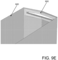
- FIG. 9E illustrates an exemplary cut away of a bag 920 not according to the invention. including a hinge.
- the exemplary hinge includes a first portion and second portion that rotate relative to each other. As illustrated, the first portion and second portion are integrally formed to define a unitary body. The body includes an axis of rotation 916 permitting the relative rotation of the first portion to the second portion.
- the hinge includes a retention interface.
- the first portion and second portion each includes two extensions 906 defining a gap 910 there between. The respective extensions of each portion contact to form the axis of rotation.
- the extension of the first portion includes a stop 934 and the extension of the second portion includes an end stop 936 that contact each other when the hinge is in the extended configuration.
- the retention interface includes the respective end stops 934, 936.
- the retention interface may also include an extendable member 932. The bias imposed by the extendable member and the limits of relative rotation of the first portion and the second portion created by the contact between the respective end stops may be used to retain the hinge in the extended configuration. As illustrated, when the hinge is in the bent configuration, the extendable member may be positioned in the gap between the extensions of the first portion and the second portion.
- FIGS. 10-14 illustrate exemplary versions of a hinge not according to the invention.
- FIGS. 10-14 include versions of a hinge similar to that described in FIGS. FIGS. 9A-9D , and have a first portion 1002, 1102, 1202, 1302, 1402 and second portion 1004, 1104, 1204, 1304, 1404 and corresponding end stops on each of the portions.
- FIGS. 10-11 illustrate exemplary configurations of an elastic member 1032, 1132 extending between the first portion and the second portion. The elastic member is coupled between the first portion and the second portion and configured to impose a bias on the hinge to retain the first portion relative to the second portion is a desired configuration.
- FIGS. 12-14 illustrate exemplary retention interfaces that may be included.
- end stop 1234 and 1236 may include mated hook and loop fasteners or other connector to removably attach the respective surfaces together.
- Other removable fasteners may also be used such as an adhesive, snaps, mated surfaces, frictional engagements, etc.
- FIGS. 13-14 illustrate exemplary frictional engagements.
- end stop 1334 may include an aperture 1330, 1430 or recess and end stop 1336 or second portion 1304, 1404 may include an extension 1314, 1414 that fits within aperture 1330, 1430.
- the extension and aperture may define a mated surface such that they frictionally engage.
- the extension and/or aperture may also include a lip or other projection to also engage.
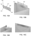
- an aperture 1544 and extension 1542 are on the same first portion 1502 of the hinge.
- the hinge includes a second axis of rotation 1546 such that portions of the first portion are able to rotate or move relative to other portions of the first portion.
- the hinge is permitted to fold about a first axis of rotation, and fold separately around a second axis of rotation.
- the first axis of rotation may be perpendicular to a second axis of rotation.
- FIGS. 16A-16B illustrate, in a cut away perspective view and cross sectional view, an exemplary version of a hinge not according to the invention.
- the exemplary hinge includes a first portion 1602 and second portion 1604 that rotate or move relative to each other. As illustrated, the first portion and second portion are separately formed to define a attachable bodies.
- the hinge includes a retention interface.
- the exemplary retention interface includes a frictional engagement similar to other versions described herein.
- the retention interface includes an aperture 1630 and extension 1614 that engage. As illustrated, the aperture 1630 is on a projection or lip of the first portion.
- the second portion 1604 is therefore retained within or between portions of the first portion 1602.
- the aperture 1630 may also include indentations in which the extension 1614 fits within, such as an indent, detent mated interface.
- FIG. 17 illustrates a cut away perspective view of a hinge not according to the invention.
- the exemplary hinge includes a first portion and second portion that rotate or move relative to each other. As illustrated, the first portion and second portion are separately formed to define a attachable bodies.
- the hinge includes a retention interface. Similar to the retention interface of FIGS. 16A-16B , the retention interface of FIG. 17 retains a portion of one portion within the other portion.
- the second portion includes an extension 1752 including a lip that extends about at least two sides of the first portion 1702. A pair of extensions on the second portion therefore retain the first portion therein.
- the retention interface may therefore simply include the slide attachment of one portion to the other portion.
- the first portion may therefore move relative to the second portion may removing the respective portions from the retention interface and move the portion out of contact of each other.
- the first portion and/or second portion may also include an axis of rotation 1716 that permits the rotation of one portion relative to the second portion.
- the first portion and second portion may therefore remain coupled within the slide of the other.
- the retention interface retains the relative position of the first portion to the second portion by overlapping the first portion and second portion across the axis of rotation such that one portion contacts the other portion having the axis of rotation on both sides of the axis of rotation acting as a stop or limit against further rotation about the axis in at least one direction.
- the slide may create a limit against further rotation about the axis in another direction.
- the hinge may be substantially planar.
- the hinge may be substantially flat in a bent configuration. As such, the hinge may allow the container to lie approximately flat when the hinge is in the bent configuration.
- the hinge may be substantially linear, and/or flat in an extended configuration.
- the hinge in an extended configuration may correspond to a container in an open configuration.
- the bag may stand significantly upright when the bag is in the expanded or open configuration.
- the first and second walls may be substantially flexible.
- the first and second hinges may be positioned on the first and second walls, respectively, and may be configured to stiffen the first and second walls, such that the first and second walls may remain substantially upright when the first and second hinges are in the expanded configuration.
- the first wall may further include a first indentation that facilitates a folding of the first wall. A central portion of the first hinge may align with the first indentation. When the first hinge is in the open or expanded configuration, the first hinge may reduce or limit folding of the first wall.
- the second wall may further include a second indentation that facilitates a folding of the second wall. A central portion of the second hinge may align with the second indentation. When the second hinge is in the expanded configuration, the second hinge may limit the folding of the second wall.
- the central portion of the first and second hinge may define an axis of rotation or a location of relative movement between the first portion and the second portion of the hinge.
- a bag having hinges according to embodiments described herein may have a first configuration and a second configuration.
- the bag in a second configuration may lie substantially flat.
- the bag may be able to transition from the first configuration to the second configuration.
Landscapes
- Engineering & Computer Science (AREA)
- Mechanical Engineering (AREA)
- Rigid Containers With Two Or More Constituent Elements (AREA)
- Closures For Containers (AREA)
Claims (8)
- Behälter (520) mit einem Scharnier (100) und ferner mit einer Oberfläche, die einen internen Hohlraum und eine Zugang zu dem Hohlraum bietende Öffnung aufweist, wobei die Oberfläche eine oder mehrere Faltlinien aufweist, um das Biegen entlang der Faltlinie zu erleichtern, so dass der Behälter eine erste, zusammengeklappte Konfiguration, in der die Oberfläche an einer oder mehreren der ein oder mehreren Faltlinien gebogen ist, und eine zweite, expandierte Konfiguration umfasst;wobei das Scharnier (100) quer zur Faltlinie positioniert ist, wobei das Scharnier (100) so positioniert ist, dass es ein Biegen um die Faltlinie in einer ersten Konfiguration zulässt und ein Biegen um die Faltlinie in einer zweiten Konfiguration begrenzt, undwobei das Scharnier (100) einen ersten Vorsprung (108, 208, 308, 408) und einen zweiten Vorsprung (114, 214, 314, 414) aufweist, wobei jeder Vorsprung die Drehachse (416) kreuzt, und dadurch gekennzeichnet, dass das Scharnier (100) eine Bewegung mit dem ersten Vorsprung (108, 208, 308, 408) auf einer ersten Seite des zweiten Vorsprungs (114, 214, 314, 414) zulässt und eine Bewegung mit dem ersten Vorsprung (108, 208, 308, 408) auf einer zweiten Seite des zweiten Vorsprungs (114, 214, 314, 414), gegenüber der ersten Seite, begrenzt.
- Behälter (520) nach Anspruch 1, wobei das Scharnier (100) einen ersten Abschnitt (102, 202, 302, 402) und einen zweiten Abschnitt (104, 204, 304, 404) aufweist, wobei sich der erste Abschnitt (102, 202, 302, 402) relativ zum zweiten Abschnitt (104, 204, 304, 404) in der ersten Konfiguration drehen kann.
- Behälter (520) nach Anspruch 2, wobei der erste Scharnierabschnitt (102, 202, 302, 402) und der zweite Scharnierabschnitt (104, 204, 304, 404) jeweils einen länglichen Körper umfassen.
- Behälter (520) nach Anspruch 3, wobei der erste Abschnitt (102, 202, 302, 402) und der zweite Abschnitt (104, 204, 304, 404) einstückig gekoppelt sind, um einen einzigen Körper zu bilden.
- Behälter (520) nach Anspruch 1, wobei das Scharnier (100) einen länglichen Körper umfasst und eine Drehachse (416) aufweist, die ein Biegen um die Drehachse (416) zulässt.
- Behälter (520) nach Anspruch 1, wobei das Scharnier (100) eine Vorspannung in Richtung einer kollabierten Konfiguration aufweist.
- Behälter (520) nach Anspruch 1, wobei das Scharnier (100) ein Filmscharnier umfasst.
- Behälter (520) nach Anspruch 1, wobei der Behälter (520) ein Beutel (820) ist.
Applications Claiming Priority (2)
| Application Number | Priority Date | Filing Date | Title |
|---|---|---|---|
| US201862730500P | 2018-09-12 | 2018-09-12 | |
| PCT/US2019/050888 WO2020056189A1 (en) | 2018-09-12 | 2019-09-12 | Container with hinge |
Publications (4)
| Publication Number | Publication Date |
|---|---|
| EP3849914A1 EP3849914A1 (de) | 2021-07-21 |
| EP3849914A4 EP3849914A4 (de) | 2022-06-15 |
| EP3849914B1 true EP3849914B1 (de) | 2024-07-03 |
| EP3849914C0 EP3849914C0 (de) | 2024-07-03 |
Family
ID=69778494
Family Applications (1)
| Application Number | Title | Priority Date | Filing Date |
|---|---|---|---|
| EP19858810.5A Active EP3849914B1 (de) | 2018-09-12 | 2019-09-12 | Behälter mit scharnier |
Country Status (4)
| Country | Link |
|---|---|
| US (1) | US12065284B2 (de) |
| EP (1) | EP3849914B1 (de) |
| CA (1) | CA3112537A1 (de) |
| WO (1) | WO2020056189A1 (de) |
Families Citing this family (6)
| Publication number | Priority date | Publication date | Assignee | Title |
|---|---|---|---|---|
| CA3112537A1 (en) | 2018-09-12 | 2020-03-19 | KeepCool USA LLC | Container with hinge |
| US11338524B1 (en) | 2018-10-26 | 2022-05-24 | Afl Telecommunications Llc | Method of forming a foldable or collapsible plastic and/or composite utility enclosure |
| US11374386B2 (en) | 2018-10-26 | 2022-06-28 | Afl Telecommunications Llc | Foldable and/or collapsible plastic/composite utility enclosure |
| US11349281B1 (en) | 2018-10-26 | 2022-05-31 | Afl Telecommunications Llc | Foldable and/or collapsible plastic/composite utility enclosure |
| US12119505B2 (en) | 2019-07-29 | 2024-10-15 | Brightz, ltd. | Multi-purpose battery pack |
| US11816941B2 (en) * | 2019-10-01 | 2023-11-14 | Keep Labs Inc. | Secure storage container, system for secure storage, and method for using a secure storage container |
Family Cites Families (13)
| Publication number | Priority date | Publication date | Assignee | Title |
|---|---|---|---|---|
| US2166360A (en) * | 1937-03-15 | 1939-07-18 | Lewis David | Bottom for bags |
| FR1073581A (fr) * | 1953-01-28 | 1954-09-27 | Réceptacle et en particulier sac de dame pliable en position de non utilisation | |
| US3034551A (en) * | 1959-03-31 | 1962-05-15 | Klehr Kenneth | Pressurized friction joint for hand luggage |
| US4815866A (en) * | 1986-03-20 | 1989-03-28 | Martone David M | Expandable container frame |
| WO1995021774A1 (en) * | 1994-02-14 | 1995-08-17 | Bradford Company | Collapsible pallet box |
| US5971187A (en) * | 1995-12-15 | 1999-10-26 | Clee; Michael | Hinge for a collapsible container |
| US8066136B2 (en) * | 2004-04-13 | 2011-11-29 | S.C. Johnson Home Storage, Inc. | Collapsible storage device |
| US8678650B2 (en) * | 2009-03-10 | 2014-03-25 | Danielle Z. Savage | Flexible package and method thereof |
| EP2550891B1 (de) * | 2011-07-26 | 2017-04-12 | Reisenthel, Peter | Zusammenklappbare Tragevorrichtung |
| WO2013028982A2 (en) * | 2011-08-24 | 2013-02-28 | Bip S.A.R.L. | Novel folding luggage and duffles and hinges therefor |
| US10597197B2 (en) * | 2012-07-16 | 2020-03-24 | Vishaal B. Verma | Bistable pull-snap hold open mechanism and method |
| GB2527750A (en) * | 2014-06-24 | 2016-01-06 | Carol Smith | Support structures |
| CA3112537A1 (en) | 2018-09-12 | 2020-03-19 | KeepCool USA LLC | Container with hinge |
-
2019
- 2019-09-12 CA CA3112537A patent/CA3112537A1/en active Pending
- 2019-09-12 WO PCT/US2019/050888 patent/WO2020056189A1/en not_active Ceased
- 2019-09-12 EP EP19858810.5A patent/EP3849914B1/de active Active
- 2019-12-05 US US16/703,886 patent/US12065284B2/en active Active
Also Published As
| Publication number | Publication date |
|---|---|
| EP3849914C0 (de) | 2024-07-03 |
| US12065284B2 (en) | 2024-08-20 |
| CA3112537A1 (en) | 2020-03-19 |
| WO2020056189A1 (en) | 2020-03-19 |
| US20200122886A1 (en) | 2020-04-23 |
| EP3849914A4 (de) | 2022-06-15 |
| EP3849914A1 (de) | 2021-07-21 |
Similar Documents
| Publication | Publication Date | Title |
|---|---|---|
| US12065284B2 (en) | Container with hinge | |
| US20100018241A1 (en) | Collapsible container | |
| US6644488B1 (en) | Combination gum and mint caddy | |
| CA2273556A1 (en) | Foldable container | |
| EP3782502B1 (de) | Aufbewahrungsbeutel mit verbesserter innensichtbarkeit | |
| JP3187051B2 (ja) | モジュール式ファイリングおよび保管システム | |
| US20110062093A1 (en) | Device for file storage | |
| WO1998046489A1 (en) | Collapsible container | |
| HK40054603A (en) | Container with hinge | |
| HK40054603B (en) | Container with hinge | |
| CN100558603C (zh) | 折叠式容器 | |
| KR200323165Y1 (ko) | 절첩식 박스 | |
| US20060291753A1 (en) | Craft bag | |
| US20070228059A1 (en) | Container | |
| EP2078680A1 (de) | Formfeste Faltschachtel | |
| US9873284B2 (en) | Device with slidable retractable stand | |
| JP5172433B2 (ja) | 財布 | |
| EP0659144B1 (de) | Verriegelungsvorrichtung für lösbare teile | |
| WO2022238817A1 (en) | Foldable case | |
| JP3123548U (ja) | 折畳み式の収納箱 | |
| EP2251271B1 (de) | Beutel | |
| US20080112653A1 (en) | Collapsible Shopping Bag With Closed End Formed By Overlapping Interlocking Portions | |
| CN223791940U (zh) | 一种包装盒 | |
| US20070278281A1 (en) | Carton handle | |
| JP3158505U (ja) | 簡易キャリーケース |
Legal Events
| Date | Code | Title | Description |
|---|---|---|---|
| STAA | Information on the status of an ep patent application or granted ep patent |
Free format text: STATUS: THE INTERNATIONAL PUBLICATION HAS BEEN MADE |
|
| PUAI | Public reference made under article 153(3) epc to a published international application that has entered the european phase |
Free format text: ORIGINAL CODE: 0009012 |
|
| STAA | Information on the status of an ep patent application or granted ep patent |
Free format text: STATUS: REQUEST FOR EXAMINATION WAS MADE |
|
| 17P | Request for examination filed |
Effective date: 20210310 |
|
| AK | Designated contracting states |
Kind code of ref document: A1 Designated state(s): AL AT BE BG CH CY CZ DE DK EE ES FI FR GB GR HR HU IE IS IT LI LT LU LV MC MK MT NL NO PL PT RO RS SE SI SK SM TR |
|
| DAV | Request for validation of the european patent (deleted) | ||
| DAX | Request for extension of the european patent (deleted) | ||
| REG | Reference to a national code |
Ref country code: HK Ref legal event code: DE Ref document number: 40054603 Country of ref document: HK |
|
| A4 | Supplementary search report drawn up and despatched |
Effective date: 20220513 |
|
| RIC1 | Information provided on ipc code assigned before grant |
Ipc: B65D 6/18 20060101ALI20220509BHEP Ipc: A45C 13/00 20060101ALI20220509BHEP Ipc: A45C 7/00 20060101ALI20220509BHEP Ipc: B65D 30/20 20060101AFI20220509BHEP |
|
| GRAP | Despatch of communication of intention to grant a patent |
Free format text: ORIGINAL CODE: EPIDOSNIGR1 |
|
| STAA | Information on the status of an ep patent application or granted ep patent |
Free format text: STATUS: GRANT OF PATENT IS INTENDED |
|
| INTG | Intention to grant announced |
Effective date: 20240207 |
|
| GRAS | Grant fee paid |
Free format text: ORIGINAL CODE: EPIDOSNIGR3 |
|
| GRAA | (expected) grant |
Free format text: ORIGINAL CODE: 0009210 |
|
| STAA | Information on the status of an ep patent application or granted ep patent |
Free format text: STATUS: THE PATENT HAS BEEN GRANTED |
|
| AK | Designated contracting states |
Kind code of ref document: B1 Designated state(s): AL AT BE BG CH CY CZ DE DK EE ES FI FR GB GR HR HU IE IS IT LI LT LU LV MC MK MT NL NO PL PT RO RS SE SI SK SM TR |
|
| REG | Reference to a national code |
Ref country code: CH Ref legal event code: EP |
|
| REG | Reference to a national code |
Ref country code: DE Ref legal event code: R096 Ref document number: 602019054769 Country of ref document: DE |
|
| U01 | Request for unitary effect filed |
Effective date: 20240703 |
|
| U07 | Unitary effect registered |
Designated state(s): AT BE BG DE DK EE FI FR IT LT LU LV MT NL PT SE SI Effective date: 20240711 |
|
| U20 | Renewal fee for the european patent with unitary effect paid |
Year of fee payment: 6 Effective date: 20240719 |
|
| PG25 | Lapsed in a contracting state [announced via postgrant information from national office to epo] |
Ref country code: NO Free format text: LAPSE BECAUSE OF FAILURE TO SUBMIT A TRANSLATION OF THE DESCRIPTION OR TO PAY THE FEE WITHIN THE PRESCRIBED TIME-LIMIT Effective date: 20241003 |
|
| PG25 | Lapsed in a contracting state [announced via postgrant information from national office to epo] |
Ref country code: GR Free format text: LAPSE BECAUSE OF FAILURE TO SUBMIT A TRANSLATION OF THE DESCRIPTION OR TO PAY THE FEE WITHIN THE PRESCRIBED TIME-LIMIT Effective date: 20241004 Ref country code: PL Free format text: LAPSE BECAUSE OF FAILURE TO SUBMIT A TRANSLATION OF THE DESCRIPTION OR TO PAY THE FEE WITHIN THE PRESCRIBED TIME-LIMIT Effective date: 20240703 |
|
| PG25 | Lapsed in a contracting state [announced via postgrant information from national office to epo] |
Ref country code: IS Free format text: LAPSE BECAUSE OF FAILURE TO SUBMIT A TRANSLATION OF THE DESCRIPTION OR TO PAY THE FEE WITHIN THE PRESCRIBED TIME-LIMIT Effective date: 20241103 |
|
| PG25 | Lapsed in a contracting state [announced via postgrant information from national office to epo] |
Ref country code: HR Free format text: LAPSE BECAUSE OF FAILURE TO SUBMIT A TRANSLATION OF THE DESCRIPTION OR TO PAY THE FEE WITHIN THE PRESCRIBED TIME-LIMIT Effective date: 20240703 Ref country code: CZ Free format text: LAPSE BECAUSE OF FAILURE TO SUBMIT A TRANSLATION OF THE DESCRIPTION OR TO PAY THE FEE WITHIN THE PRESCRIBED TIME-LIMIT Effective date: 20240703 |
|
| PG25 | Lapsed in a contracting state [announced via postgrant information from national office to epo] |
Ref country code: ES Free format text: LAPSE BECAUSE OF FAILURE TO SUBMIT A TRANSLATION OF THE DESCRIPTION OR TO PAY THE FEE WITHIN THE PRESCRIBED TIME-LIMIT Effective date: 20240703 Ref country code: RS Free format text: LAPSE BECAUSE OF FAILURE TO SUBMIT A TRANSLATION OF THE DESCRIPTION OR TO PAY THE FEE WITHIN THE PRESCRIBED TIME-LIMIT Effective date: 20241003 |
|
| PG25 | Lapsed in a contracting state [announced via postgrant information from national office to epo] |
Ref country code: RS Free format text: LAPSE BECAUSE OF FAILURE TO SUBMIT A TRANSLATION OF THE DESCRIPTION OR TO PAY THE FEE WITHIN THE PRESCRIBED TIME-LIMIT Effective date: 20241003 Ref country code: PL Free format text: LAPSE BECAUSE OF FAILURE TO SUBMIT A TRANSLATION OF THE DESCRIPTION OR TO PAY THE FEE WITHIN THE PRESCRIBED TIME-LIMIT Effective date: 20240703 Ref country code: NO Free format text: LAPSE BECAUSE OF FAILURE TO SUBMIT A TRANSLATION OF THE DESCRIPTION OR TO PAY THE FEE WITHIN THE PRESCRIBED TIME-LIMIT Effective date: 20241003 Ref country code: IS Free format text: LAPSE BECAUSE OF FAILURE TO SUBMIT A TRANSLATION OF THE DESCRIPTION OR TO PAY THE FEE WITHIN THE PRESCRIBED TIME-LIMIT Effective date: 20241103 Ref country code: HR Free format text: LAPSE BECAUSE OF FAILURE TO SUBMIT A TRANSLATION OF THE DESCRIPTION OR TO PAY THE FEE WITHIN THE PRESCRIBED TIME-LIMIT Effective date: 20240703 Ref country code: GR Free format text: LAPSE BECAUSE OF FAILURE TO SUBMIT A TRANSLATION OF THE DESCRIPTION OR TO PAY THE FEE WITHIN THE PRESCRIBED TIME-LIMIT Effective date: 20241004 Ref country code: ES Free format text: LAPSE BECAUSE OF FAILURE TO SUBMIT A TRANSLATION OF THE DESCRIPTION OR TO PAY THE FEE WITHIN THE PRESCRIBED TIME-LIMIT Effective date: 20240703 Ref country code: CZ Free format text: LAPSE BECAUSE OF FAILURE TO SUBMIT A TRANSLATION OF THE DESCRIPTION OR TO PAY THE FEE WITHIN THE PRESCRIBED TIME-LIMIT Effective date: 20240703 |
|
| PG25 | Lapsed in a contracting state [announced via postgrant information from national office to epo] |
Ref country code: SM Free format text: LAPSE BECAUSE OF FAILURE TO SUBMIT A TRANSLATION OF THE DESCRIPTION OR TO PAY THE FEE WITHIN THE PRESCRIBED TIME-LIMIT Effective date: 20240703 |
|
| PG25 | Lapsed in a contracting state [announced via postgrant information from national office to epo] |
Ref country code: MC Free format text: LAPSE BECAUSE OF FAILURE TO SUBMIT A TRANSLATION OF THE DESCRIPTION OR TO PAY THE FEE WITHIN THE PRESCRIBED TIME-LIMIT Effective date: 20240703 |
|
| PG25 | Lapsed in a contracting state [announced via postgrant information from national office to epo] |
Ref country code: SK Free format text: LAPSE BECAUSE OF FAILURE TO SUBMIT A TRANSLATION OF THE DESCRIPTION OR TO PAY THE FEE WITHIN THE PRESCRIBED TIME-LIMIT Effective date: 20240703 |
|
| REG | Reference to a national code |
Ref country code: CH Ref legal event code: PL |
|
| PLBE | No opposition filed within time limit |
Free format text: ORIGINAL CODE: 0009261 |
|
| STAA | Information on the status of an ep patent application or granted ep patent |
Free format text: STATUS: NO OPPOSITION FILED WITHIN TIME LIMIT |
|
| 26N | No opposition filed |
Effective date: 20250404 |
|
| PG25 | Lapsed in a contracting state [announced via postgrant information from national office to epo] |
Ref country code: CH Free format text: LAPSE BECAUSE OF NON-PAYMENT OF DUE FEES Effective date: 20240930 |
|
| PG25 | Lapsed in a contracting state [announced via postgrant information from national office to epo] |
Ref country code: IE Free format text: LAPSE BECAUSE OF NON-PAYMENT OF DUE FEES Effective date: 20240912 |
|
| U20 | Renewal fee for the european patent with unitary effect paid |
Year of fee payment: 7 Effective date: 20250829 |
|
| PGFP | Annual fee paid to national office [announced via postgrant information from national office to epo] |
Ref country code: GB Payment date: 20250821 Year of fee payment: 7 |
|
| PG25 | Lapsed in a contracting state [announced via postgrant information from national office to epo] |
Ref country code: RO Free format text: LAPSE BECAUSE OF FAILURE TO SUBMIT A TRANSLATION OF THE DESCRIPTION OR TO PAY THE FEE WITHIN THE PRESCRIBED TIME-LIMIT Effective date: 20240703 |
|
| PG25 | Lapsed in a contracting state [announced via postgrant information from national office to epo] |
Ref country code: CY Free format text: LAPSE BECAUSE OF FAILURE TO SUBMIT A TRANSLATION OF THE DESCRIPTION OR TO PAY THE FEE WITHIN THE PRESCRIBED TIME-LIMIT; INVALID AB INITIO Effective date: 20190912 |
|
| PG25 | Lapsed in a contracting state [announced via postgrant information from national office to epo] |
Ref country code: HU Free format text: LAPSE BECAUSE OF FAILURE TO SUBMIT A TRANSLATION OF THE DESCRIPTION OR TO PAY THE FEE WITHIN THE PRESCRIBED TIME-LIMIT; INVALID AB INITIO Effective date: 20190912 |