EP3849930B1 - Système de levage de pale de rotor et procédé d'installation et/ou de désinstallation d'une pale de rotor - Google Patents
Système de levage de pale de rotor et procédé d'installation et/ou de désinstallation d'une pale de rotor Download PDFInfo
- Publication number
- EP3849930B1 EP3849930B1 EP19770024.8A EP19770024A EP3849930B1 EP 3849930 B1 EP3849930 B1 EP 3849930B1 EP 19770024 A EP19770024 A EP 19770024A EP 3849930 B1 EP3849930 B1 EP 3849930B1
- Authority
- EP
- European Patent Office
- Prior art keywords
- rotor blade
- clamping
- wind turbine
- swing arm
- hoisting
- Prior art date
- Legal status (The legal status is an assumption and is not a legal conclusion. Google has not performed a legal analysis and makes no representation as to the accuracy of the status listed.)
- Active
Links
Images





Classifications
-
- B—PERFORMING OPERATIONS; TRANSPORTING
- B66—HOISTING; LIFTING; HAULING
- B66C—CRANES; LOAD-ENGAGING ELEMENTS OR DEVICES FOR CRANES, CAPSTANS, WINCHES, OR TACKLES
- B66C1/00—Load-engaging elements or devices attached to lifting or lowering gear of cranes or adapted for connection therewith for transmitting lifting forces to articles or groups of articles
- B66C1/10—Load-engaging elements or devices attached to lifting or lowering gear of cranes or adapted for connection therewith for transmitting lifting forces to articles or groups of articles by mechanical means
- B66C1/108—Load-engaging elements or devices attached to lifting or lowering gear of cranes or adapted for connection therewith for transmitting lifting forces to articles or groups of articles by mechanical means for lifting parts of wind turbines
-
- F—MECHANICAL ENGINEERING; LIGHTING; HEATING; WEAPONS; BLASTING
- F03—MACHINES OR ENGINES FOR LIQUIDS; WIND, SPRING, OR WEIGHT MOTORS; PRODUCING MECHANICAL POWER OR A REACTIVE PROPULSIVE THRUST, NOT OTHERWISE PROVIDED FOR
- F03D—WIND MOTORS
- F03D13/00—Assembly, mounting or commissioning of wind motors; Arrangements specially adapted for transporting wind motor components
- F03D13/10—Assembly of wind motors; Arrangements for erecting wind motors
-
- F—MECHANICAL ENGINEERING; LIGHTING; HEATING; WEAPONS; BLASTING
- F03—MACHINES OR ENGINES FOR LIQUIDS; WIND, SPRING, OR WEIGHT MOTORS; PRODUCING MECHANICAL POWER OR A REACTIVE PROPULSIVE THRUST, NOT OTHERWISE PROVIDED FOR
- F03D—WIND MOTORS
- F03D80/00—Details, components or accessories not provided for in groups F03D1/00 - F03D17/00
- F03D80/50—Maintenance or repair
-
- F—MECHANICAL ENGINEERING; LIGHTING; HEATING; WEAPONS; BLASTING
- F05—INDEXING SCHEMES RELATING TO ENGINES OR PUMPS IN VARIOUS SUBCLASSES OF CLASSES F01-F04
- F05B—INDEXING SCHEME RELATING TO WIND, SPRING, WEIGHT, INERTIA OR LIKE MOTORS, TO MACHINES OR ENGINES FOR LIQUIDS COVERED BY SUBCLASSES F03B, F03D AND F03G
- F05B2230/00—Manufacture
- F05B2230/60—Assembly methods
- F05B2230/61—Assembly methods using auxiliary equipment for lifting or holding
-
- Y—GENERAL TAGGING OF NEW TECHNOLOGICAL DEVELOPMENTS; GENERAL TAGGING OF CROSS-SECTIONAL TECHNOLOGIES SPANNING OVER SEVERAL SECTIONS OF THE IPC; TECHNICAL SUBJECTS COVERED BY FORMER USPC CROSS-REFERENCE ART COLLECTIONS [XRACs] AND DIGESTS
- Y02—TECHNOLOGIES OR APPLICATIONS FOR MITIGATION OR ADAPTATION AGAINST CLIMATE CHANGE
- Y02E—REDUCTION OF GREENHOUSE GAS [GHG] EMISSIONS, RELATED TO ENERGY GENERATION, TRANSMISSION OR DISTRIBUTION
- Y02E10/00—Energy generation through renewable energy sources
- Y02E10/70—Wind energy
- Y02E10/72—Wind turbines with rotation axis in wind direction
-
- Y—GENERAL TAGGING OF NEW TECHNOLOGICAL DEVELOPMENTS; GENERAL TAGGING OF CROSS-SECTIONAL TECHNOLOGIES SPANNING OVER SEVERAL SECTIONS OF THE IPC; TECHNICAL SUBJECTS COVERED BY FORMER USPC CROSS-REFERENCE ART COLLECTIONS [XRACs] AND DIGESTS
- Y02—TECHNOLOGIES OR APPLICATIONS FOR MITIGATION OR ADAPTATION AGAINST CLIMATE CHANGE
- Y02P—CLIMATE CHANGE MITIGATION TECHNOLOGIES IN THE PRODUCTION OR PROCESSING OF GOODS
- Y02P70/00—Climate change mitigation technologies in the production process for final industrial or consumer products
- Y02P70/50—Manufacturing or production processes characterised by the final manufactured product
Definitions
- the present invention relates to a rotor blade hoisting system for installation and/or deinstallation of a rotor blade on a hub of a wind turbine, the rotor blade hoisting system including an upper cable support system adapted to be mounted on a top end of the wind turbine, a lower cable support system adapted to be arranged at a lower end of the wind turbine at a distance from the wind turbine, at least a left and a right cable both adapted to be extended, in spaced relationship, between the upper cable support system and the lower cable support system, a clamping system adapted to be clamped onto a rotor blade of the wind turbine, the clamping system including a left climbing system adapted to climb on the left cable and a right climbing system adapted to climb on the right cable, each of the left and the right climbing systems including at least a first and a second roller adapted to roll on the respective cable and adapted to, when the clamping system is clamped onto the rotor blade, be spaced in a longitudinal direction of the rotor
- DK 2014 00575 A1 discloses a method of replacement of a rotor blade on a wind turbine, wherein wires are extended between a lower land based wire support system and an upper wire support system being mounted on the wind turbine rotor.
- a first clamp is mounted on the root end of the rotor blade and a second clamp is mounted on the tip end of the rotor blade.
- Each clamp runs on the wires by means of trolleys and at least one motor driven wire climbing hoist is associated with each wire and a respective clamp.
- a conventional land based crane higher than the wind turbine may be dispensed with.
- WO 2018/054440 A1 discloses a further development of the above-mentioned method of replacement of a rotor blade on a wind turbine, wherein the clamping system and hoisting system has been improved.
- the document discloses a rotor blade hoisting system in accordance with the preamble of claim 1.
- US 2011/0185571 A1 discloses a method of installing wind turbine blades utilizing a clamp which is adapted to be removably connected to each of the blades and which in turn may be connected to a hook of a crane which may be installed near the tower of the wind turbine.
- the clamp may be adapted to rotate a clamped blade around a transverse axis of the blade and/or to rotate a clamped blade around a longitudinal axis of the clamped blade.
- the object of the present invention is to provide a rotor blade hoisting system of the type mentioned by way of introduction, whereby the torque transferred by the blade during installation may be effectively reduced compared to prior art systems, and whereby manoeuvring of the rotor blade may be facilitated.
- the clamping system includes a clamping yoke adapted to be arranged approximately at the position of the centre of gravity of the rotor blade, at least in the longitudinal direction of the rotor blade, the left and the right climbing systems are mounted on the clamping yoke, and, when the clamping system is clamped onto the rotor blade, a position at least in the longitudinal direction of the rotor blade of the first roller of at least one of the left and the right climbing systems is adjustable by means of an actuator.
- the rotor blade may be carried by means of a single clamping yoke incorporating both first and second rollers of the left and right climbing systems, and it may thereby be avoided that torque is transferred by the rotor blade from one yoke to another.
- the manoeuvring of the rotor blade during hoisting may be improved compared to prior art systems, even if the yoke construction is made very compact.
- the rotor blade may, when oriented horizontally, be rotated about a vertical axis, so that the blade may be positioned on the ground in an oblique angle to a line between the wind turbine tower and the lower cable support system, thereby requiring less space on the ground. Because such rotation of the wind turbine blade during hoisting may be obtained without pulling the cables, strength requirements of the system may be reduced.
- the rotor blade may be rotated about a vertical axis, more flexibility may be obtained by adjusting said longitudinal position of both a left and a right first roller and this may therefore be preferred.
- a position of the first roller of each of the left and the right climbing systems is individually adjustable by means of an actuator at least in a specific direction extending transversely to the longitudinal direction of the rotor blade.
- Said specific direction preferably extends at least substantially in the direction of a chord of the rotor blade.
- the orientation of the rotor blade may, during hoisting, be adapted to the required orientation for mounting on the hub of the wind turbine, i.e. an orientation wherein the longitudinal direction of the rotor blade extends at least substantially in vertical direction.
- this orientation of the rotor blade may be performed by means of said actuator or actuators, it may not be necessary pulling the left and/or right cable forcefully during hoisting.
- manoeuvring of the rotor blade may indeed be facilitated, and furthermore, strength requirements of the entire hoisting system may be reduced.
- the upper cable support system adapted to be mounted on a top end of the wind turbine and the left and right cables may be designed to carry reduced loads as compared to prior art systems.
- a direct distance between the first rollers of the left and the right climbing systems, respectively is freely variable within certain limits.
- the distance between the first rollers may more or less adapt automatically to a distance between the left and right cables being suspended from the upper cable support system.
- a direct distance between the first rollers of the left and the right climbing systems, respectively is individually adjustable by means of at least one actuator.
- the distance between the first rollers may be controlled independently of a distance between the left and right cables being suspended from the upper cable support system. As a result, even more precise control of the hoisting process may be obtained.
- the first roller of at least one of the left and the right climbing systems is arranged on a swing arm being arranged on the clamping system, and a swing arm actuator is arranged to swing said swing arm in relation to the clamping system.
- the swing arm is arranged pivotally on the clamping system generally about a main pivot axis extending transversely in relation to the rotor blade, when the clamping system is clamped onto the rotor blade, and the swing arm actuator is arranged to pivot said swing arm generally about said main pivot axis.
- said swing arm is composed by a first section and a second section being pivotally linked. Thereby, a further possibility of adjustment of the position of the first roller may be obtained.
- said swing arm is composed by a first section and a second section being pivotally linked together about an auxiliary pivot axis extending transversely to the main pivot axis.
- the distance between the first rollers may more or less adapt to a distance between the left and right cables being suspended from the upper cable support system.
- an auxiliary swing arm actuator is arranged to pivot the first section and the second section in relation to each other.
- the distance between the first rollers may be controlled independently of a distance between the left and right cables being suspended from the upper cable support system. As a result, even more precise control of the hoisting process may be obtained.
- the present invention further relates to a method of installation and/or deinstallation of a rotor blade on a hub of a wind turbine, the method including the following steps: mounting an upper cable support system on a top end of the wind turbine, arranging a lower cable support system at a lower end of the wind turbine at a distance from the wind turbine, extending, in spaced relationship, at least a left and a right cable between the upper cable support system and the lower cable support system, clamping a clamping system onto a rotor blade, arranging a left climbing system of the clamping system on the left cable and a right climbing system of the clamping system on the right cable, each of the left and the right climbing systems including at least a first and a second roller rolling on the respective cable and being spaced in a longitudinal direction of the rotor blade, the first rollers being placed nearer a root end of the rotor blade than the second rollers, driving at least one of the first and second rollers of each of the left and the right climbing systems by means of a motor,
- the method is characterised by arranging a clamping yoke of the clamping system approximately at the position of the centre of gravity of the rotor blade, at least in the longitudinal direction of the rotor blade, the left and the right climbing systems being mounted on the clamping yoke, and by, when the rotor blade is at a first intermediate hoisting position between the lower end of the wind turbine and the top end of the wind turbine, adjusting a position at least in the longitudinal direction of the rotor blade of the first roller of at least one of the left and the right climbing systems by means of an actuator in such a way that the rotor blade yaws about a vertical axis extending in a transverse direction of the rotor blade and/or tilts about a horizontal axis extending in a transverse direction of the rotor blade.
- a position at least in a specific direction extending transversely to the longitudinal direction of the rotor blade of the first roller of each of the left and the right climbing systems is individually adjusted by means of an actuator in such a way that the rotor blade tilts about a horizontal axis extending in a transverse direction of the rotor blade.
- a relative position between the first roller of at least one of the left and the right climbing systems and the clamping yoke is adjusted by adapting the position of a swing arm arranged on the clamping yoke and carrying said first roller.
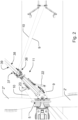
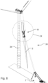
- Fig. 1 shows a rotor blade hoisting system 1 according to the present invention for installation and/or deinstallation of a rotor blade 2 on a hub 3 of a horizontal axis wind turbine 4 well known in the art.
- the rotor blade hoisting system 1 includes an upper cable support system 5 mounted on a top end 6 of the wind turbine 4 and a lower cable support system 7 arranged at a lower end 8 of the wind turbine 4 at a distance from the wind turbine.
- the upper cable support system 5 is indicated only in Fig. 2 and includes a spacer element well known in the art which is positioned between two fixed rotor blades 2', 2".
- the spacer element includes a centre section and two guide sections arranged at either fixed rotor blades 2', 2".
- the spacer element may be arranged on the fixed rotor blades 2', 2" for instance by means of slings around the root end of the rotor blades 2', 2" and may further be secured to a nacelle of the wind turbine for instance by means of separate cables.
- the two guide sections are designed to interact with a left cable 9 and a right cable 10, respectively.
- the lower cable support system 7 may the form of winch system arranged in a land based container 35 well known in the art.
- the left and right cables 9, 10 are typically metal wires, but any suitable cables may be used.
- the left and a right cables 9, 10 are extended, in spaced relationship, between the upper cable support system 5 arranged between two fixed rotor blades 2', 2" and the lower cable support system 7 based on the ground.
- a rotor blade 2 intended to be mounted on the hub 3 of the wind turbine 4 has been provided with a clamping system 11 when the rotor blade 2 was situated on the ground or very near the ground.
- the clamping system 11 includes a left climbing system 12 arranged to climb on the left cable 9 and a right climbing system 13 arranged to climb on the right cable 10.
- Each of the left and the right climbing systems 12, 13 includes a first roller 14, 16 and a second roller 15, 17 arranged to roll on the respective cable 9, 10 and being spaced in a longitudinal direction of the rotor blade 2 so that the first rollers 14, 16 are placed nearer a root end 18 of the rotor blade 2 than the second rollers 15, 17.
- the left and the right climbing systems 12, 13 includes further auxiliary rollers 43, 44.
- the second roller 15, 17 of each of the left and the right climbing systems 12, 13 is a remotely controlled motor driven roller adapted to climb on the respective cable 9, 10.
- the motor may be an electric motor or a hydraulic motor.
- a climbing hoist of this type is well known in the art and may typically function so that the cable is winded several times around the roller 15, 17, thereby providing friction between the cable and the roller.
- an end of a lower cable running to the lower cable support system 7 may be fixed on a second motor driven roller 15, 17 so that the cable is rolled up on the second roller.
- an end of an upper cable running to the upper cable support system may be fixed on another motor driven roller, for instance a first roller 14, 16, so that the corresponding cable is rolled up on that roller.
- the lower cable and the upper cable may together form the left cable 9 or the right cable 10.
- the clamping system 11 includes a clamping yoke 19 which has been arranged approximately at the centre of gravity of the rotor blade 2.
- the clamping yoke 19 includes two left clamping devices 36 abutting a first side 38 of the rotor blade 2 and two right clamping devices 37 abutting a second side 39 of the rotor blade.
- the first and second sides 38, 39 of the rotor blade 2 represent the pressure side and the suction side, respectively.
- the left clamping devices 36 and the right clamping devices 37 are arranged pivotally 42 in relation to each other and so that they may be pressed against the first and second sides 38, 39, respectively, of the rotor blade 2 by means of hydraulic actuators 40, 41.
- the left and the right climbing systems 12, 13 are mounted on the clamping yoke 19.
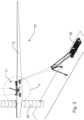
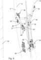
- the rotor blade 2 when the rotor blade 2 is at a first intermediate hoisting position 31 between the lower end 8 of the wind turbine 4 and the top end 6 of the wind turbine 4, the rotor blade 2 may be brought to yaw about a vertical axis extending in a transverse direction of the rotor blade 2, and preferably more or less at the centre of gravity of the rotor blade 2, by adjusting a position along the longitudinal direction of the rotor blade 2 of the first rollers 14, 16 of each of the left and the right climbing systems 12, 13 by means of respective hydraulic actuators 20, 21. According to the present invention, however, it may be sufficient to adjust a position along the longitudinal direction of the rotor blade 2 of only a single one of the first rollers 14, 16 of the left and the right climbing systems 12, 13.
- the rotor blade 2 may be rotated about a vertical axis as explained above, the rotor blade 2 intended to be mounted on the hub 3 of the wind turbine 4 may initially be positioned on the ground extending in an oblique angle to a line between the wind turbine tower 34 and the lower cable support system 7, thereby requiring less space on the ground. Furthermore, because such rotation of the wind turbine blade 2 during hoisting may be obtained without pulling the left and right cables 9, 10, strength requirements of the entire rotor blade hoisting system 1 may be reduced.
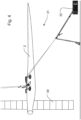
- the rotor blade 2 when the rotor blade 2 is at a second intermediate hoisting 32 position being above the first intermediate hoisting position 31, the rotor blade 2 may be brought to tilt about a horizontal axis extending in a transverse direction of the rotor blade 2, and preferably more or less at the centre of gravity of the rotor blade 2, by individually adjusting a position in a specific direction extending transversely to the longitudinal direction of the rotor blade 2 of the first roller 14, 16 of each of the left and the right climbing systems 12, 13 by means of the respective hydraulic actuators 20, 21.
- the orientation of the rotor blade 2 may, during hoisting, be adapted to the required orientation for mounting on the hub 3 of the wind turbine 4, i.e. an orientation wherein the longitudinal direction of the rotor blade 2 extends at least substantially in vertical direction.
- This orientation is illustrated as the third intermediate hoisting position 33 of rotor blade 2 in Figs. 8 and 9 .
- the orientation of the rotor blade 2 may be performed by means of said hydraulic actuators 20, 21, it may not be necessary pulling the left and right cables 9, 10 forcefully during hoisting.
- manoeuvring of the rotor blade 2 may indeed be facilitated, and furthermore, strength requirements of the entire rotor blade hoisting system 1 may be reduced.
- the upper cable support system 5 adapted to be mounted on a top end 6 of the wind turbine 4 and the left and right cables 9, 10 may be designed to carry reduced loads as compared to prior art systems.
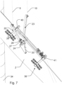
- the first rollers 14, 16 of the left and the right climbing systems 12, 13 is arranged on a left and right swing arm 22, 23 arranged on the clamping system 11, i.e. the clamping yoke 19, and the hydraulic actuators 20, 21 have the form of swing arm actuators 20, 21 arranged to swing said swing arms 22, 23 in relation to the clamping system 11.
- the swing arms 22, 23 are arranged pivotally on the clamping system 11 about main pivot axes 24, 25 extending transversely in relation to the rotor blade 2, when the clamping system 11 is clamped onto the rotor blade 2, and the swing arm actuators 20, 21 are arranged to pivot said swing arms 22, 23 about said main pivot axes 24, 25.
- a direct distance measured between the first rollers 14, 16 of the left and the right climbing systems 12, 13, respectively is freely variable within certain limits, i.e. between a minimum distance and a maximum distance.
- the distance between the first rollers 14, 16 may somewhat adapt automatically to a distance between the left and right cables 9, 10 being suspended from the upper cable support system 5.
- said respective swing arms 22, 23 are composed by a first section 26 and a second section 27 being pivotally linked together about an auxiliary pivot axis 28 extending transversely to the main pivot axis 24, 25.
- the position along the longitudinal direction of the rotor blade 2 of the first rollers 14, 16 of each of the left and the right climbing systems 12, 13 is able to be adjusted so that the distance in the longitudinal direction of the rotor blade 2 between said first rollers 14, 16 is at least the above-mentioned minimum distance measured between the first rollers 14, 16, preferably at least 1,5 times said minimum distance and more preferred at least about the double of said minimum distance.
- a direct distance measured between the first rollers 14, 16 of the left and the right climbing systems 12, 13, respectively may be individually adjustable by means of at least one actuator.
- a not shown auxiliary swing arm actuator may be arranged to pivot the first section 26 and the second section 27 in relation to each other.
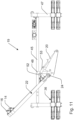
- Figs. 10 , 11 and 12 illustrate the embodiment of the clamping yoke 19 seen in Figs. 1 to 9 in more detail.
- the clamping yoke 19 has a fixed frame composed by two longitudinal rods 45 maintained in spaced relation by means of a spacer rod 46 at either end thereof.
- two opposed clamping arms 47 are arranged pivotally on the fixed frame about the pivot joint 42 having its pivot axis extending in parallel to the two longitudinal rods 45.
- Each clamping arm 47 carries a respective left or right clamping device 36, 37.
- Each longitudinal rod 45 carries a swing arm mounting rod 48 fixed thereto and extending at right angles to the longitudinal rod 45 and being arranged slightly nearer to a first end 49 than to a second end 50 of the fixed frame.
- the swing arm mounting rod 48 protrudes downward from the longitudinal rods 45 in the figures just as the clamping arms 47.
- a swing arm base rod 51 is fixed to the swing arm mounting rod 48 at a slightly oblique angle pointing upwards in the direction of the first end 49 of the fixed frame.
- On a front end of the swing arm base rod 51 a first end of the respective left or right swing arm 22, 23, made up by the second section 27 of the swing arm, is mounted pivotally about the main pivot axis 24, 25 of the left or right swing arm.
- the main pivot axes 24, 25 extend at right angles to the longitudinal rods 45 of the fixed frame of the clamping yoke 19 and in parallel to the spacer rods 46 of the fixed frame.
- the main pivot axes 24, 25 extend at right angles to the longitudinal direction of the rotor blade.
- the main pivot axes 24, 25 just extend transversely to the longitudinal direction of the rotor blade 2, but preferably at least substantially at right angles to the longitudinal direction of the rotor blade.
- the respective swing arms 22, 23 are composed by the first section 26 and the second section 27 which are pivotally linked together about the auxiliary pivot axis 28 extending at right angles to the main pivot axis 24, 25.
- the first section 26 and the second section 27 are freely pivotal within certain limits about the auxiliary pivot axis 28.
- the second section 27 of the left or right swing arm 22, 23 and therefore also the left or right swing arm 22, 23 are arranged to swing about the main pivot axis 24, 25 of the left or right swing arm by means activation of the left and right swing arm actuators 20, 21, respectively.
- the second section 27 of the left swing arm 22 is connected to the swing arm base rod 51 by means of a link mechanism composed by a first link rod 52 having its first end pivotally connected to the second section 27 and its second end pivotally connected to a first leg of an L-link 53, the other leg of which is pivotally connected to the swing arm base rod 51.
- the left swing arm actuator 20 which is a hydraulic actuator has its actuator rod connected pivotally to the middle of the L-link 53 and its actuator cylinder connected pivotally to the swing arm base rod 51.
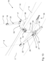
- Fig. 13 illustrates another embodiment of the clamping yoke 19 seen in Figs. 1 to 9 .
- the fixed frame of the clamping yoke 19 is formed by a single C-bracket 54 having a first leg 55 on which the left clamping device 36 is fixed and a second leg 56 on which the right clamping device 37 is arranged pivotally about a pivot joint 42 which is not visible in the figure and which has a pivot axis extending in the longitudinal direction of the rotor blade 2 on which the clamping yoke 19 is mounted.
- Each of the first and second legs 55, 56 of the C- bracket 54 carries a swing arm mounting rod 48 fixed thereto and extending in continuation thereof in the longitudinal direction of the respective leg 55, 56.
- the swing arm mounting rod 48 protrudes downward from the respective left or right clamping device 36, 37 and carries the respective left or right swing arm 22, 23 in the same way as explained above referring to the embodiment in Figs. 10 to 12 .
- the left and right second rollers 15, 17 are mounted directly on a central part of the C- bracket 54.
Landscapes
- Engineering & Computer Science (AREA)
- Mechanical Engineering (AREA)
- Life Sciences & Earth Sciences (AREA)
- Sustainable Development (AREA)
- Sustainable Energy (AREA)
- Chemical & Material Sciences (AREA)
- Combustion & Propulsion (AREA)
- General Engineering & Computer Science (AREA)
- Wind Motors (AREA)
- Turbine Rotor Nozzle Sealing (AREA)
- Structures Of Non-Positive Displacement Pumps (AREA)
- Load-Engaging Elements For Cranes (AREA)
Claims (12)
- Système de levage de pale de rotor (1) pour l'installation et/la désinstallation d'une pale de rotor (2) sur un moyeu (3) d'une éolienne (4), le système de levage de pale de rotor (1) incluant un système de support de câble supérieur (5) adapté pour être monté sur une extrémité supérieure (6) de l'éolienne (4), un système de support de câble inférieur (7) adapté pour être agencé à une extrémité inférieure (8) de l'éolienne (4) à une distance de l'éolienne, au moins un câble gauche et un câble droit (9, 10) adaptés tous les deux pour être étendus, dans un rapport espacé, entre le système de support de câble supérieur (5) et le système de support de câble inférieur (7), un système de serrage (11) adapté pour être serré sur une pale de rotor (2) de l'éolienne (4), le système de serrage (11) incluant un système d'escalade gauche (12) adapté pour l'escalade sur le câble gauche (9) et un système d'escalade droit (13) adapté pour l'escalade sur le câble droit (10), chacun des systèmes d'escalade gauche et droit (12, 13) incluant au moins un premier et un second rouleau (14, 15, 16, 17) adaptés pour rouler sur le câble respectif (9, 10) et adaptés pour, lorsque le système de serrage (11) est serré sur la pale de rotor (2), être espacés dans une direction longitudinale de la pale de rotor (2) de sorte que les premiers rouleaux (14, 16) soient placés plus près d'une extrémité de pied (18) de la pale de rotor (2) que les seconds rouleaux (15, 17), et dans lequel au moins un (15, 17) des premier et second rouleaux (14, 15, 16, 17) de chacun des systèmes d'escalade gauche et droit (12, 13) est un rouleau entraîné par moteur, caractérisé en ce que le système de serrage (11) inclut un étrier de serrage (19) adapté pour être agencé approximativement dans la position du centre de gravité de la pale de rotor (2), au moins dans la direction longitudinale de la pale de rotor, en ce que les systèmes d'escalade gauche et droit (12, 13) sont montés sur l'étrier de serrage (19), et en ce que, lorsque le système de serrage (11) est serré sur la pale de rotor (2), une position au moins dans la direction longitudinale de la pale de rotor (2) du premier rouleau (14, 16) d'au moins un des systèmes d'escalade gauche et droit (12, 13) est ajustable au moyen d'un actionneur (20, 21).
- Système de levage de pale de rotor selon la revendication 1, dans lequel lorsque le système de serrage (11) est serré sur la pale de rotor (2), une position du premier rouleau (14, 16) de chacun des systèmes d'escalade gauche et droit (12, 13) est individuellement ajustable au moyen d'un actionneur (20, 21) au moins dans une direction spécifique s'étendant transversalement à la direction longitudinale de la pale de rotor (2), et dans lequel ladite direction spécifique s'étend de préférence au moins sensiblement dans la direction d'une corde de la pale de rotor (2).
- Système de levage de pale de rotor selon la revendication 1 ou 2, dans lequel lorsque le système de serrage (11) est serré sur la pale de rotor (2), une distance directe entre les premiers rouleaux (14, 16) des systèmes d'escalade gauche et droit (12, 13) respectivement, est librement variable dans certaines limites.
- Système de levage de pale de rotor selon la revendication 1 ou 2, dans lequel lorsque le système de serrage (11) est serré sur la pale de rotor (2), une distance directe entre les premiers rouleaux (14, 16) des systèmes d'escalade gauche et droit (12, 13) respectivement, est individuellement ajustable au moyen d'au moins un actionneur.
- Système de levage de pale de rotor selon l'une quelconque des revendications précédentes, dans lequel le premier rouleau (14, 16) d'au moins un des systèmes d'escalade gauche et droit (12, 13) est agencé sur un bras de pivotement (22, 23) agencé sur le système de serrage (11), et dans lequel un actionneur de bras de pivotement (20, 21) est agencé pour faire pivoter ledit bras de pivotement (22, 23) par rapport au système de serrage (11).
- Système de levage de pale de rotor selon la revendication 5, dans lequel le bras de pivotement (22, 23) est agencé de manière pivotante sur le système de serrage (11) généralement autour d'un axe de pivotement principal (24, 25) s'étendant transversalement par rapport à la pale de rotor (2), lorsque le système de serrage (11) est serré sur la pale de rotor (2), et dans lequel l'actionneur de bras de pivotement (20, 21) est agencé pour faire pivoter ledit bras de pivotement (22, 23) généralement autour dudit axe de pivotement principal (24, 25).
- Système de levage de pale de rotor selon la revendication 5 ou 6, dans lequel ledit bras de pivotement (22, 23) est composé d'une première section (26) et d'une seconde section (27) liées de manière pivotante.
- Système de levage de pale de rotor selon la revendication 6, dans lequel ledit bras de pivotement (22, 23) est composé d'une première section (26) et d'une seconde section (27) liées de manière pivotante ensemble autour d'un axe de pivotement auxiliaire (28) s'étendant transversalement à l'axe de pivotement principal (24, 25).
- Système de levage de pale de rotor selon la revendication 7 ou 8, dans lequel un actionneur de bras de pivotement auxiliaire est agencé pour faire pivoter la première section (26) et la seconde section (27) l'une par rapport à l'autre.
- Procédé d'installation et/ou de désinstallation d'une pale de rotor (2) sur un moyeu (3) d'une éolienne (4), le procédé incluant les étapes suivantes : monter un système de support de câble supérieur (5) sur une extrémité supérieure (6) de l'éolienne (4), agencer un système de support de câble inférieur (7) à une extrémité inférieure (8) de l'éolienne (4) à une distance de l'éolienne, étendre, dans un rapport espacé, au moins un câble gauche et un câble droit (9, 10) entre le système de support de câble supérieur (5) et le système de support de câble inférieur (7), serrer un système de serrage (11) sur une pale de rotor (2), agencer un système d'escalade gauche (12) du système de serrage (11) sur le câble gauche (9) et un système d'escalade droit (13) du système de serrage (11) sur le câble droit (10), chacun des systèmes d'escalade gauche et droit (12, 13) incluant au moins un premier et un second rouleau (14, 15) roulant sur le câble respectif (9, 10) et étant espacé dans une direction longitudinale de la pale de rotor (2), les premiers rouleaux (14, 16) étant placés plus près d'une extrémité de pied (18) de la pale de rotor (2) que les seconds rouleaux (15, 17), entraîner au moins un des premier et second rouleaux (14, 15) de chacun des systèmes d'escalade gauche et droit (12, 13) au moyen d'un moteur (29, 30), levant ainsi la pale de rotor (2) vers le haut ou vers le bas, caractérisé par l'agencement d'un étrier de serrage (19) du système de serrage (11) approximativement dans la position du centre de gravité de la pale de rotor (2), au moins dans la direction longitudinale de la pale de rotor, les systèmes d'escalade gauche et droit (12, 13) étant montés sur l'étrier de serrage (19), et par, lorsque la pale de rotor (2) est dans une première position de levage intermédiaire (31) entre l'extrémité inférieure (8) de l'éolienne (4) et l'extrémité supérieure (6) de l'éolienne (4), l'ajustement d'une position au moins dans la direction longitudinale de la pale de rotor (2) du premier rouleau (14, 16) d'au moins un des systèmes de serrage gauche et droit (12, 13) au moyen d'un actionneur (20, 21) de telle manière que la pale de rotor (2) s'oriente autour d'un axe vertical s'étendant dans une direction transversale de la pale de rotor (2) et/ou s'incline autour d'un axe horizontal s'étendant dans une direction transversale de la pale de rotor (2).
- Procédé d'installation et/ou de désinstallation d'une pale de rotor selon la revendication 10, selon lequel, lorsque la pale de rotor (2) est dans une seconde position de levage intermédiaire (32) au-dessus de la première position de levage intermédiaire (31), une position au moins dans une direction spécifique s'étendant transversalement à la direction longitudinale de la pale de rotor (2) du premier rouleau (14, 16) de chacun des systèmes d'escalade gauche et droit (12, 13) est ajustée individuellement au moyen d'un actionneur (20, 21) de telle manière que la pale de rotor (2) s'incline autour d'un axe horizontal s'étendant dans une direction transversale de la pale de rotor (2).
- Procédé d'installation et/ou de désinstallation d'une pale de rotor selon la revendication 10 ou 11, selon lequel une position relative entre le premier rouleau (14, 16) d'au moins un des systèmes d'escalade gauche et droit (12, 13) et l'étrier de serrage (19) est ajustée par adaptation de la position d'un bras de pivotement (22, 23) agencé sur l'étrier de serrage (19) et port dudit premier rouleau (14, 16).
Applications Claiming Priority (2)
| Application Number | Priority Date | Filing Date | Title |
|---|---|---|---|
| DKPA201870585A DK180504B1 (en) | 2018-09-13 | 2018-09-13 | Rotor blade hoisting system and method for mounting and / or removing a rotor blade |
| PCT/EP2019/074494 WO2020053389A1 (fr) | 2018-09-13 | 2019-09-13 | Système de levage de pale de rotor et procédé d'installation et/ou de désinstallation d'une pale de rotor |
Publications (3)
| Publication Number | Publication Date |
|---|---|
| EP3849930A1 EP3849930A1 (fr) | 2021-07-21 |
| EP3849930C0 EP3849930C0 (fr) | 2023-07-12 |
| EP3849930B1 true EP3849930B1 (fr) | 2023-07-12 |
Family
ID=67997590
Family Applications (1)
| Application Number | Title | Priority Date | Filing Date |
|---|---|---|---|
| EP19770024.8A Active EP3849930B1 (fr) | 2018-09-13 | 2019-09-13 | Système de levage de pale de rotor et procédé d'installation et/ou de désinstallation d'une pale de rotor |
Country Status (6)
| Country | Link |
|---|---|
| US (1) | US12434946B2 (fr) |
| EP (1) | EP3849930B1 (fr) |
| CN (1) | CN112638815B (fr) |
| DK (1) | DK180504B1 (fr) |
| ES (1) | ES2952162T3 (fr) |
| WO (1) | WO2020053389A1 (fr) |
Families Citing this family (8)
| Publication number | Priority date | Publication date | Assignee | Title |
|---|---|---|---|---|
| DK181351B1 (en) * | 2019-03-01 | 2023-08-23 | Liftra Ip Aps | Crane system for hoisting of wind turbine components and method for moving a burden |
| US12188453B2 (en) * | 2020-04-02 | 2025-01-07 | Aerones, Inc. | Arrangement for lowering and raising service tools used for wind turbine blade and tower maintenance |
| CN112695639B (zh) * | 2020-12-25 | 2022-08-19 | 上海浦兴路桥建设工程有限公司 | 一种以原桥梁为基础吊装新高架桥梁的施工方法 |
| CN112942094B (zh) * | 2021-01-27 | 2022-12-06 | 中铁二十一局集团第三工程有限公司 | 一种用于桥梁底部的检查设备 |
| CN115448143B (zh) * | 2022-09-20 | 2026-04-24 | 阿巴嘎旗绿能新能源有限公司 | 陆上风电场建造用的旋叶吊运设备及其定位组件 |
| AU2022491199A1 (en) * | 2022-12-20 | 2025-06-19 | Nabrawind Technologies, S.L. | Guiding system for exchanging a wind turbine blade and use method |
| DK181779B1 (en) * | 2023-02-02 | 2024-12-13 | Liftra Ip Aps | A method for controlling the position of a blade lifting yoke and a blade lifting yoke for a rotor blade for a wind turbine |
| GB2631523B (en) | 2023-07-05 | 2025-11-12 | Seaway 7 Eng B V | Upending elongate structures offshore |
Family Cites Families (26)
| Publication number | Priority date | Publication date | Assignee | Title |
|---|---|---|---|---|
| US1928213A (en) * | 1932-05-10 | 1933-09-26 | Jr Lewis M Showers | Lifting sling |
| US4883184A (en) * | 1986-05-23 | 1989-11-28 | Albus James S | Cable arrangement and lifting platform for stabilized load lifting |
| CA2520168C (fr) * | 2003-04-15 | 2009-08-11 | Vestas Wind Systems A/S | Procede d'entretien des elements exterieurs d'une eolienne tels que les pales et le pylone a l'aide d'une plate-forme de travail, et plate-forme de travail |
| DE102004056340B4 (de) | 2004-11-22 | 2010-11-18 | Repower Systems Ag | Vorrichtung und Verfahren zur Montage und/oder Demontage eines Bauteils einer Windkraftanlage |
| EP1666401B1 (fr) * | 2004-12-03 | 2011-06-22 | Manitowoc Crane Group Germany GmbH | Grue mobile |
| EP1925582B1 (fr) * | 2006-11-23 | 2010-06-23 | Siemens Aktiengesellschaft | Procédé et dispositif de montage de pales d'éoliennes |
| US8191878B2 (en) * | 2007-04-30 | 2012-06-05 | Vestas Wind Systems A/S | Mounting device |
| NO326937B1 (no) * | 2007-06-29 | 2009-03-16 | Seatower | Anordning og fremgangsmate ved marin tarnstruktur |
| US20100139062A1 (en) * | 2009-02-25 | 2010-06-10 | General Electric Company | Lowering and raising a single wind turbine rotor blade from six-o'clock position |
| EP2345811B1 (fr) | 2010-01-14 | 2012-10-03 | Siemens Aktiengesellschaft | Pince pour fixer la pale d'une éolienne et procédé d'installation de pales d'éolienne |
| ES2371703B1 (es) | 2010-01-14 | 2012-11-21 | Gamesa Innovation & Technology, S.L. | Elemento para izado de pala y método seguido. |
| ES2564260T3 (es) * | 2010-11-18 | 2016-03-21 | Vestas Wind Systems A/S | Método para manipular sin grúa una pala de turbina eólica por medio de un buje de turbina |
| US20110140060A1 (en) | 2010-11-29 | 2011-06-16 | General Electric Company | System and method for locating a maintenance device approximate an area of interest of a wind turbine |
| DK177338B1 (da) | 2011-01-11 | 2013-01-21 | Liftra Aps | Hjælperedskab for løft af tunge og relativt lange emner, navnlig vinger til vindmøller |
| ES2481794T3 (es) * | 2011-02-04 | 2014-07-31 | Lm Wp Patent Holding A/S | Montaje de dispositivos generadores de torbellinos sobre una pala de rotor de turbina eólica por medio de placa de montaje |
| DK2686550T3 (en) * | 2011-03-17 | 2016-10-24 | Vestas Wind Sys As | An apparatus for gaining access to the nacelle of a wind turbine and associated methods |
| US8360398B2 (en) * | 2011-08-17 | 2013-01-29 | General Electric Company | Device for handling a wind turbine rotor blade and a method for handling wind turbine rotor blades |
| DK177672B1 (da) | 2012-11-27 | 2014-02-17 | Liftra Ip Aps | Løfteramme |
| KR20150045114A (ko) * | 2013-10-18 | 2015-04-28 | 삼성중공업 주식회사 | 블레이드 설치용 리프팅 지그 |
| US9638163B2 (en) * | 2014-02-20 | 2017-05-02 | General Electric Company | Methods and systems for removing and/or installing wind turbine rotor blades |
| US10113530B2 (en) * | 2014-02-20 | 2018-10-30 | General Electric Company | Methods and systems for removing and/or installing wind turbine rotor blades |
| KR20160148682A (ko) * | 2014-04-30 | 2016-12-26 | 윈드케어 인디아 피브이티 엘티디 | 풍력터빈 날개의 해체 및 조립 방법과 시스템 |
| DK178627B1 (da) * | 2014-10-08 | 2016-09-19 | Liftra Ip Aps | Fremgangsmåde til anvendelse ved enkeltvingeskift på en vindmølle, samt indretning til udøvelse af fremgangsmåden. |
| DK179302B1 (en) * | 2016-09-24 | 2018-04-16 | Liftra Ip Aps | Rotor blade replacement system |
| DK180210B1 (en) * | 2017-10-23 | 2020-08-18 | Eltronic Wind Solutions As | System for craneless blade mounting and dismounting on a wind turbine |
| US10988351B2 (en) * | 2018-08-31 | 2021-04-27 | LiftWerx Holdings Inc. | Nacelle-mounted lift system for wind turbine |
-
2018
- 2018-09-13 DK DKPA201870585A patent/DK180504B1/en active IP Right Grant
-
2019
- 2019-09-13 EP EP19770024.8A patent/EP3849930B1/fr active Active
- 2019-09-13 US US17/270,703 patent/US12434946B2/en active Active
- 2019-09-13 ES ES19770024T patent/ES2952162T3/es active Active
- 2019-09-13 WO PCT/EP2019/074494 patent/WO2020053389A1/fr not_active Ceased
- 2019-09-13 CN CN201980057231.7A patent/CN112638815B/zh active Active
Also Published As
| Publication number | Publication date |
|---|---|
| DK180504B1 (en) | 2021-06-03 |
| BR112021003909A2 (pt) | 2021-05-18 |
| US20220348441A1 (en) | 2022-11-03 |
| ES2952162T3 (es) | 2023-10-27 |
| CN112638815B (zh) | 2023-09-22 |
| WO2020053389A1 (fr) | 2020-03-19 |
| DK201870585A1 (en) | 2020-04-23 |
| US12434946B2 (en) | 2025-10-07 |
| EP3849930C0 (fr) | 2023-07-12 |
| CN112638815A (zh) | 2021-04-09 |
| EP3849930A1 (fr) | 2021-07-21 |
Similar Documents
| Publication | Publication Date | Title |
|---|---|---|
| US12434946B2 (en) | Rotor blade hoisting system and method of installation and/or deinstallation of a rotor blade | |
| EP3972926B1 (fr) | Tour d'éolienne dotée d'éléments de raccordement de grue et grue dotée d'éléments de raccordement de bride de tour | |
| CA2611343C (fr) | Methode et dispositif d'installation de pales d'eolienne | |
| JP7353289B2 (ja) | 物体を配置するためのクレーンおよび方法 | |
| CA2823574C (fr) | Eolienne et procede de reglage de l'axe de rotation du rotor | |
| US9494133B2 (en) | Method for lowering and raising a wind turbine blade | |
| EP2924278B1 (fr) | Outil permettant de manipuler un objet lourd et long | |
| JP2011144808A (ja) | 風車のための翼を締め付けるためのクランプ及び風車の翼を取り付ける方法 | |
| EP2589795B1 (fr) | Cadre de levage pour lever une pale de rotor d'éolienne et procédé de montage de pales de rotor d'éolienne | |
| EP3902764B1 (fr) | Procédé de manipulation d'un composant d'éolienne avec un agencement de commande | |
| US11760608B2 (en) | Wind turbine blade removal device and method | |
| KR102931658B1 (ko) | 크레인을 포함하는 결합체와, 크레인에 장착하기 위해 배치된 하중 안내 장치 및 상기 결합체에 사용하기 위한 하중 안내 장치 | |
| EP4222373B1 (fr) | Agencement de levage destiné à une plateforme d'accès à une pale d'éolienne | |
| CN120187663A (zh) | 能使转子转动的提升轭架 | |
| BR112021003909B1 (pt) | Sistema de içamento da pá do rotor e método de instalação e/ou desinstalação de uma pá do rotor | |
| CN220845080U (zh) | 一种具有变桨功能的吊具挂架 |
Legal Events
| Date | Code | Title | Description |
|---|---|---|---|
| STAA | Information on the status of an ep patent application or granted ep patent |
Free format text: STATUS: UNKNOWN |
|
| STAA | Information on the status of an ep patent application or granted ep patent |
Free format text: STATUS: THE INTERNATIONAL PUBLICATION HAS BEEN MADE |
|
| PUAI | Public reference made under article 153(3) epc to a published international application that has entered the european phase |
Free format text: ORIGINAL CODE: 0009012 |
|
| STAA | Information on the status of an ep patent application or granted ep patent |
Free format text: STATUS: REQUEST FOR EXAMINATION WAS MADE |
|
| 17P | Request for examination filed |
Effective date: 20210309 |
|
| AK | Designated contracting states |
Kind code of ref document: A1 Designated state(s): AL AT BE BG CH CY CZ DE DK EE ES FI FR GB GR HR HU IE IS IT LI LT LU LV MC MK MT NL NO PL PT RO RS SE SI SK SM TR |
|
| DAX | Request for extension of the european patent (deleted) | ||
| RAV | Requested validation state of the european patent: fee paid |
Extension state: MA Effective date: 20210309 |
|
| GRAP | Despatch of communication of intention to grant a patent |
Free format text: ORIGINAL CODE: EPIDOSNIGR1 |
|
| STAA | Information on the status of an ep patent application or granted ep patent |
Free format text: STATUS: GRANT OF PATENT IS INTENDED |
|
| INTG | Intention to grant announced |
Effective date: 20220420 |
|
| GRAJ | Information related to disapproval of communication of intention to grant by the applicant or resumption of examination proceedings by the epo deleted |
Free format text: ORIGINAL CODE: EPIDOSDIGR1 |
|
| STAA | Information on the status of an ep patent application or granted ep patent |
Free format text: STATUS: REQUEST FOR EXAMINATION WAS MADE |
|
| INTC | Intention to grant announced (deleted) | ||
| GRAP | Despatch of communication of intention to grant a patent |
Free format text: ORIGINAL CODE: EPIDOSNIGR1 |
|
| STAA | Information on the status of an ep patent application or granted ep patent |
Free format text: STATUS: GRANT OF PATENT IS INTENDED |
|
| INTG | Intention to grant announced |
Effective date: 20230202 |
|
| GRAS | Grant fee paid |
Free format text: ORIGINAL CODE: EPIDOSNIGR3 |
|
| GRAA | (expected) grant |
Free format text: ORIGINAL CODE: 0009210 |
|
| STAA | Information on the status of an ep patent application or granted ep patent |
Free format text: STATUS: THE PATENT HAS BEEN GRANTED |
|
| AK | Designated contracting states |
Kind code of ref document: B1 Designated state(s): AL AT BE BG CH CY CZ DE DK EE ES FI FR GB GR HR HU IE IS IT LI LT LU LV MC MK MT NL NO PL PT RO RS SE SI SK SM TR |
|
| REG | Reference to a national code |
Ref country code: CH Ref legal event code: EP |
|
| REG | Reference to a national code |
Ref country code: DE Ref legal event code: R096 Ref document number: 602019032644 Country of ref document: DE |
|
| REG | Reference to a national code |
Ref country code: IE Ref legal event code: FG4D |
|
| U01 | Request for unitary effect filed |
Effective date: 20230712 |
|
| U07 | Unitary effect registered |
Designated state(s): AT BE BG DE DK EE FI FR IT LT LU LV MT NL PT SE SI Effective date: 20230720 |
|
| REG | Reference to a national code |
Ref country code: ES Ref legal event code: FG2A Ref document number: 2952162 Country of ref document: ES Kind code of ref document: T3 Effective date: 20231027 |
|
| U20 | Renewal fee for the european patent with unitary effect paid |
Year of fee payment: 5 Effective date: 20230925 |
|
| REG | Reference to a national code |
Ref country code: LT Ref legal event code: MG9D |
|
| PG25 | Lapsed in a contracting state [announced via postgrant information from national office to epo] |
Ref country code: GR Free format text: LAPSE BECAUSE OF FAILURE TO SUBMIT A TRANSLATION OF THE DESCRIPTION OR TO PAY THE FEE WITHIN THE PRESCRIBED TIME-LIMIT Effective date: 20231013 |
|
| PG25 | Lapsed in a contracting state [announced via postgrant information from national office to epo] |
Ref country code: IS Free format text: LAPSE BECAUSE OF FAILURE TO SUBMIT A TRANSLATION OF THE DESCRIPTION OR TO PAY THE FEE WITHIN THE PRESCRIBED TIME-LIMIT Effective date: 20231112 |
|
| PG25 | Lapsed in a contracting state [announced via postgrant information from national office to epo] |
Ref country code: RS Free format text: LAPSE BECAUSE OF FAILURE TO SUBMIT A TRANSLATION OF THE DESCRIPTION OR TO PAY THE FEE WITHIN THE PRESCRIBED TIME-LIMIT Effective date: 20230712 Ref country code: NO Free format text: LAPSE BECAUSE OF FAILURE TO SUBMIT A TRANSLATION OF THE DESCRIPTION OR TO PAY THE FEE WITHIN THE PRESCRIBED TIME-LIMIT Effective date: 20231012 Ref country code: IS Free format text: LAPSE BECAUSE OF FAILURE TO SUBMIT A TRANSLATION OF THE DESCRIPTION OR TO PAY THE FEE WITHIN THE PRESCRIBED TIME-LIMIT Effective date: 20231112 Ref country code: HR Free format text: LAPSE BECAUSE OF FAILURE TO SUBMIT A TRANSLATION OF THE DESCRIPTION OR TO PAY THE FEE WITHIN THE PRESCRIBED TIME-LIMIT Effective date: 20230712 Ref country code: GR Free format text: LAPSE BECAUSE OF FAILURE TO SUBMIT A TRANSLATION OF THE DESCRIPTION OR TO PAY THE FEE WITHIN THE PRESCRIBED TIME-LIMIT Effective date: 20231013 |
|
| PG25 | Lapsed in a contracting state [announced via postgrant information from national office to epo] |
Ref country code: PL Free format text: LAPSE BECAUSE OF FAILURE TO SUBMIT A TRANSLATION OF THE DESCRIPTION OR TO PAY THE FEE WITHIN THE PRESCRIBED TIME-LIMIT Effective date: 20230712 |
|
| REG | Reference to a national code |
Ref country code: DE Ref legal event code: R097 Ref document number: 602019032644 Country of ref document: DE |
|
| U1N | Appointed representative for the unitary patent procedure changed after the registration of the unitary effect |
Representative=s name: MUENZER, MARC ERIC; DK |
|
| PG25 | Lapsed in a contracting state [announced via postgrant information from national office to epo] |
Ref country code: SM Free format text: LAPSE BECAUSE OF FAILURE TO SUBMIT A TRANSLATION OF THE DESCRIPTION OR TO PAY THE FEE WITHIN THE PRESCRIBED TIME-LIMIT Effective date: 20230712 Ref country code: RO Free format text: LAPSE BECAUSE OF FAILURE TO SUBMIT A TRANSLATION OF THE DESCRIPTION OR TO PAY THE FEE WITHIN THE PRESCRIBED TIME-LIMIT Effective date: 20230712 Ref country code: CZ Free format text: LAPSE BECAUSE OF FAILURE TO SUBMIT A TRANSLATION OF THE DESCRIPTION OR TO PAY THE FEE WITHIN THE PRESCRIBED TIME-LIMIT Effective date: 20230712 Ref country code: SK Free format text: LAPSE BECAUSE OF FAILURE TO SUBMIT A TRANSLATION OF THE DESCRIPTION OR TO PAY THE FEE WITHIN THE PRESCRIBED TIME-LIMIT Effective date: 20230712 |
|
| REG | Reference to a national code |
Ref country code: CH Ref legal event code: PL |
|
| PLBE | No opposition filed within time limit |
Free format text: ORIGINAL CODE: 0009261 |
|
| STAA | Information on the status of an ep patent application or granted ep patent |
Free format text: STATUS: NO OPPOSITION FILED WITHIN TIME LIMIT |
|
| PG25 | Lapsed in a contracting state [announced via postgrant information from national office to epo] |
Ref country code: MC Free format text: LAPSE BECAUSE OF FAILURE TO SUBMIT A TRANSLATION OF THE DESCRIPTION OR TO PAY THE FEE WITHIN THE PRESCRIBED TIME-LIMIT Effective date: 20230712 |
|
| 26N | No opposition filed |
Effective date: 20240415 |
|
| REG | Reference to a national code |
Ref country code: IE Ref legal event code: MM4A |
|
| PG25 | Lapsed in a contracting state [announced via postgrant information from national office to epo] |
Ref country code: IE Free format text: LAPSE BECAUSE OF NON-PAYMENT OF DUE FEES Effective date: 20230913 |
|
| PG25 | Lapsed in a contracting state [announced via postgrant information from national office to epo] |
Ref country code: CH Free format text: LAPSE BECAUSE OF NON-PAYMENT OF DUE FEES Effective date: 20230930 |
|
| PG25 | Lapsed in a contracting state [announced via postgrant information from national office to epo] |
Ref country code: IE Free format text: LAPSE BECAUSE OF NON-PAYMENT OF DUE FEES Effective date: 20230913 Ref country code: CH Free format text: LAPSE BECAUSE OF NON-PAYMENT OF DUE FEES Effective date: 20230930 |
|
| U20 | Renewal fee for the european patent with unitary effect paid |
Year of fee payment: 6 Effective date: 20240925 |
|
| PG25 | Lapsed in a contracting state [announced via postgrant information from national office to epo] |
Ref country code: CY Free format text: LAPSE BECAUSE OF FAILURE TO SUBMIT A TRANSLATION OF THE DESCRIPTION OR TO PAY THE FEE WITHIN THE PRESCRIBED TIME-LIMIT; INVALID AB INITIO Effective date: 20190913 |
|
| PG25 | Lapsed in a contracting state [announced via postgrant information from national office to epo] |
Ref country code: HU Free format text: LAPSE BECAUSE OF FAILURE TO SUBMIT A TRANSLATION OF THE DESCRIPTION OR TO PAY THE FEE WITHIN THE PRESCRIBED TIME-LIMIT; INVALID AB INITIO Effective date: 20190913 |
|
| PGFP | Annual fee paid to national office [announced via postgrant information from national office to epo] |
Ref country code: GB Payment date: 20250919 Year of fee payment: 7 |
|
| U20 | Renewal fee for the european patent with unitary effect paid |
Year of fee payment: 7 Effective date: 20250924 |
|
| PG25 | Lapsed in a contracting state [announced via postgrant information from national office to epo] |
Ref country code: TR Free format text: LAPSE BECAUSE OF FAILURE TO SUBMIT A TRANSLATION OF THE DESCRIPTION OR TO PAY THE FEE WITHIN THE PRESCRIBED TIME-LIMIT Effective date: 20230712 |
|
| PGFP | Annual fee paid to national office [announced via postgrant information from national office to epo] |
Ref country code: ES Payment date: 20251030 Year of fee payment: 7 |
|
| VS25 | Lapsed in a validation state [announced via postgrant information from nat. office to epo] |
Ref country code: MA Free format text: LAPSE BECAUSE OF FAILURE TO SUBMIT A TRANSLATION OF THE DESCRIPTION OR TO PAY THE FEE WITHIN THE PRESCRIBED TIME-LIMIT Effective date: 20230712 |