EP3850404B1 - Techniques de diagraphie par résonance magnétique nucléaire avec des réseaux d'antennes - Google Patents
Techniques de diagraphie par résonance magnétique nucléaire avec des réseaux d'antennes Download PDFInfo
- Publication number
- EP3850404B1 EP3850404B1 EP19859129.9A EP19859129A EP3850404B1 EP 3850404 B1 EP3850404 B1 EP 3850404B1 EP 19859129 A EP19859129 A EP 19859129A EP 3850404 B1 EP3850404 B1 EP 3850404B1
- Authority
- EP
- European Patent Office
- Prior art keywords
- antenna
- antennae
- nmr
- measurement
- instrument
- Prior art date
- Legal status (The legal status is an assumption and is not a legal conclusion. Google has not performed a legal analysis and makes no representation as to the accuracy of the status listed.)
- Active
Links
Images





Classifications
-
- G—PHYSICS
- G01—MEASURING; TESTING
- G01V—GEOPHYSICS; GRAVITATIONAL MEASUREMENTS; DETECTING MASSES OR OBJECTS; TAGS
- G01V3/00—Electric or magnetic prospecting or detecting; Measuring magnetic field characteristics of the earth, e.g. declination, deviation
- G01V3/08—Electric or magnetic prospecting or detecting; Measuring magnetic field characteristics of the earth, e.g. declination, deviation operating with magnetic or electric fields produced or modified by objects or geological structures or by detecting devices
- G01V3/10—Electric or magnetic prospecting or detecting; Measuring magnetic field characteristics of the earth, e.g. declination, deviation operating with magnetic or electric fields produced or modified by objects or geological structures or by detecting devices using induction coils
- G01V3/104—Electric or magnetic prospecting or detecting; Measuring magnetic field characteristics of the earth, e.g. declination, deviation operating with magnetic or electric fields produced or modified by objects or geological structures or by detecting devices using induction coils using several coupled or uncoupled coils
-
- E—FIXED CONSTRUCTIONS
- E21—EARTH OR ROCK DRILLING; MINING
- E21B—EARTH OR ROCK DRILLING; OBTAINING OIL, GAS, WATER, SOLUBLE OR MELTABLE MATERIALS OR A SLURRY OF MINERALS FROM WELLS
- E21B47/00—Survey of boreholes or wells
- E21B47/02—Determining slope or direction
- E21B47/026—Determining slope or direction of penetrated ground layers
-
- G—PHYSICS
- G01—MEASURING; TESTING
- G01N—INVESTIGATING OR ANALYSING MATERIALS BY DETERMINING THEIR CHEMICAL OR PHYSICAL PROPERTIES
- G01N24/00—Investigating or analyzing materials by the use of nuclear magnetic resonance, electron paramagnetic resonance or other spin effects
- G01N24/08—Investigating or analyzing materials by the use of nuclear magnetic resonance, electron paramagnetic resonance or other spin effects by using nuclear magnetic resonance
- G01N24/081—Making measurements of geologic samples, e.g. measurements of moisture, pH, porosity, permeability, tortuosity or viscosity
-
- G—PHYSICS
- G01—MEASURING; TESTING
- G01R—MEASURING ELECTRIC VARIABLES; MEASURING MAGNETIC VARIABLES
- G01R33/00—Arrangements or instruments for measuring magnetic variables
- G01R33/20—Arrangements or instruments for measuring magnetic variables involving magnetic resonance
- G01R33/28—Details of apparatus provided for in groups G01R33/44 - G01R33/64
- G01R33/32—Excitation or detection systems, e.g. using radio frequency signals
- G01R33/34—Constructional details, e.g. resonators, specially adapted to MR
- G01R33/341—Constructional details, e.g. resonators, specially adapted to MR comprising surface coils
- G01R33/3415—Constructional details, e.g. resonators, specially adapted to MR comprising surface coils comprising arrays of sub-coils, i.e. phased-array coils with flexible receiver channels
-
- G—PHYSICS
- G01—MEASURING; TESTING
- G01V—GEOPHYSICS; GRAVITATIONAL MEASUREMENTS; DETECTING MASSES OR OBJECTS; TAGS
- G01V3/00—Electric or magnetic prospecting or detecting; Measuring magnetic field characteristics of the earth, e.g. declination, deviation
- G01V3/18—Electric or magnetic prospecting or detecting; Measuring magnetic field characteristics of the earth, e.g. declination, deviation specially adapted for well-logging
- G01V3/26—Electric or magnetic prospecting or detecting; Measuring magnetic field characteristics of the earth, e.g. declination, deviation specially adapted for well-logging operating with magnetic or electric fields produced or modified either by the surrounding earth formation or by the detecting device
- G01V3/28—Electric or magnetic prospecting or detecting; Measuring magnetic field characteristics of the earth, e.g. declination, deviation specially adapted for well-logging operating with magnetic or electric fields produced or modified either by the surrounding earth formation or by the detecting device using induction coils
-
- G—PHYSICS
- G01—MEASURING; TESTING
- G01V—GEOPHYSICS; GRAVITATIONAL MEASUREMENTS; DETECTING MASSES OR OBJECTS; TAGS
- G01V3/00—Electric or magnetic prospecting or detecting; Measuring magnetic field characteristics of the earth, e.g. declination, deviation
- G01V3/18—Electric or magnetic prospecting or detecting; Measuring magnetic field characteristics of the earth, e.g. declination, deviation specially adapted for well-logging
- G01V3/32—Electric or magnetic prospecting or detecting; Measuring magnetic field characteristics of the earth, e.g. declination, deviation specially adapted for well-logging operating with electron or nuclear magnetic resonance
-
- G—PHYSICS
- G01—MEASURING; TESTING
- G01V—GEOPHYSICS; GRAVITATIONAL MEASUREMENTS; DETECTING MASSES OR OBJECTS; TAGS
- G01V3/00—Electric or magnetic prospecting or detecting; Measuring magnetic field characteristics of the earth, e.g. declination, deviation
- G01V3/18—Electric or magnetic prospecting or detecting; Measuring magnetic field characteristics of the earth, e.g. declination, deviation specially adapted for well-logging
- G01V3/34—Transmitting data to recording or processing apparatus; Recording data
Definitions
- This disclosure relates to techniques for NMR logging of downhole formations using downhole tools that include at least one antenna array.
- Producing hydrocarbons from a wellbore drilled into a geological formation is a remarkably complex endeavor. In many cases, decisions involved in hydrocarbon exploration and production may be informed by measurements from downhole well-logging tools that are conveyed deep into the wellbore. The measurements may be used to infer properties or characteristics of the geological formation surrounding the wellbore.
- NMR nuclear magnetic resonance
- Many NMR tools have a permanent magnet that produces a static magnetic field at a desired test location (e.g., where the fluid is located).
- the static magnetic field produces an equilibrium magnetization in the fluid that is aligned with a magnetization vector along the direction of the static magnetic field.
- a transmitter antenna produces a time-dependent radio frequency magnetic field that is perpendicular to the direction of the static field.
- the radio frequency magnetic field produces a torque on the magnetization vector that causes it to rotate about the axis of the applied radio frequency magnetic field.
- the rotation results in the magnetization vector developing a component perpendicular to the direction of the static magnetic field. This causes the magnetization vector to align with the component perpendicular to the direction of the static magnetic field, and to precess around the static field.
- the document US 9759832 B1 describes a nuclear magnetic resonance (NMR) measurement method and apparatus for well logging.
- the apparatus includes a magnet, a transmitter antenna and at least one of a receiver section of the transmit antenna, or a separate receiver antenna, having a length along the longitudinal dimension of the apparatus, which is shorter than a length of the transmitter antenna along the longitudinal dimension.
- the apparatus includes circuitry for applying radio frequency (RF) current pulses, for example a Carr-Purcell-Meiboom-Gill pulse sequence, to the entire transmitter antenna and for receiving signals by the at least one of the receiver section of the transmitter antenna and the separate receiver antenna.
- RF radio frequency
- a single or multiple antennas may overcome spin echo signal amplitude reduction caused by the loss of transverse magnetization as a result of instrument motion.
- transmit mode the entire length, or the longer antenna, may be used to transmit RF pulses, whereas in receive mode only the lower part of the antenna, or a shorter antenna is connected to receiver circuitry in the instrument to detect NMR signals from the measurement region.
- a measurement starts at a first longitudinal position in a borehole, with a measurement made at a first frequency and thus in a measurement region during receiving RF signals induced by NMR phenomena.
- v speed of motion of the well logging instrument
- Tm measurement time
- downhole logging techniques may employ multiple methods (e.g., gamma-ray spectroscopy, resistivity logging, NMR spectroscopy etc.) to characterize a downhole formation.
- Each of the methods are complementary and the combination of multiple methods may provide a more complete picture of the downhole formation.
- characterization of a downhole formation is more efficient.
- One challenge in oilfield formation evaluation is the ability to log advanced NMR applications at rates closer to the rates of other logging methods.
- FIG. 1A shows an example embodiment of an apparatus for investigating subsurface formations 31 penetrated by a wellbore 32, which can be used in performing various embodiments of a method according to the present disclosure.
- a well logging instrument 30 may be suspended in the borehole 32 on an armored electrical cable 33, the length of which substantially determines the relative depth of the well logging instrument 30.
- the cable 33 may be extended into the wellbore 32 and withdrawn therefrom by suitable means at the surface such as a drum and winch mechanism 34.
- suitable means at the surface such as a drum and winch mechanism 34.
- Other conveyance devices for moving the well logging instrument 30 such as slickline or coiled tubing may also use a winch mechanism as shown in FIG. 1A .
- Surface equipment, represented at 7, can be of any type know in the art for operation well logging instruments, and may include a processor subsystem, signal communication and recording devices and a telemetry transceiver for communicating with the well logging instrument 30.
- the well logging instrument which makes the measurements can be any suitable NMR well logging device, for use in "wireline" conveyed well logging instrumentation as shown in FIG. 1A , or of a type that can be used in logging while drilling (LWD) applications to be explained below with reference to FIG. 1B .
- the well logging instrument 30 includes, for example, a magnet such as a permanent magnet, magnet array, electromagnet or combinations thereof for inducing a static magnetic field in the formations 31, and one or more radio frequency (RF) antennas for inducing a pulsed RF magnetic field in the formations 31 and for receiving RF energy induced by NMR phenomena excited in the formations 31.
- RF radio frequency
- the well logging instrument described above can also be implemented, for example, in logging-while-drilling ("LWD") equipment.
- LWD logging-while-drilling
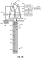
- a platform and derrick 210 are positioned over a wellbore 212 that may be formed in the Earth by rotary drilling.
- a drill string 214 may be suspended within the borehole and may include a drill bit 216 attached thereto and rotated by a rotary table 218 (energized by means not shown) which engages a kelly 220 at the upper end of the drill string 214.
- the drill string 214 is typically suspended from a hook 222 attached to a traveling block (not shown).
- the kelly 220 may be connected to the hook 222 through a rotary swivel 224 which permits rotation of the drill string 214 relative to the hook 222.
- the drill string 214 and drill bit 216 may be rotated from the surface by a "top drive" type of drilling rig.
- Drilling fluid or mud 226 is contained in a mud pit 228 adjacent to the derrick 210.
- a pump 230 pumps the drilling fluid 226 into the drill string 214 via a port in the swivel 224 to flow downward (as indicated by the flow arrow 232) through the center of the drill string 214.
- the drilling fluid exits the drill string via ports in the drill bit 216 and then circulates upward in the annular space between the outside of the drill string 214 and the wall of the wellbore 212, as indicated by the flow arrows 234.
- the drilling fluid 226 thereby lubricates the bit and carries formation cuttings to the surface of the earth.
- the drilling fluid is returned to the mud pit 228 for recirculation.
- a directional drilling assembly could also be employed.
- a bottom hole assembly (“BHA”) 236 may be mounted within the drill string 214, in some cases near the drill bit 216.
- the BHA 236 may include subassemblies for making measurements, processing and storing information and for communicating with the Earth's surface. Such measurements may correspond to those made using the NMR well logging instrument explained above with reference to FIG. 1A .
- the bottom hole assembly is typically located within several drill collar lengths of the drill bit 216. In the illustrated BHA 236, a stabilizer collar section 238 is shown disposed immediately above the drill bit 216, followed in the upward direction by a drill collar section 240, another stabilizer collar section 242 and another drill collar section 244.
- the components of the NMR well logging instrument may be located, for example, in the drill collar section 240 above the stabilizer collar 238. Such components could, if desired, be located closer to or farther from the drill bit 216, such as, for example, in either stabilizer collar section 238 or 242 or the drill collar section 244.
- the BHA 236 may also include a telemetry subassembly (not shown) for data and control communication with the Earth's surface.
- a telemetry subassembly may be of any suitable type, e.g., a mud pulse (pressure or acoustic) telemetry system, wired drill pipe, etc., which receives output signals from LWD measuring instruments in the BHA 236 (including the NMR well logging instrument) and transmits encoded signals representative of such outputs to the surface where the signals are detected, decoded in a receiver subsystem 246, and applied to a processor 248 and/or a recorder 250.
- the processor 248 may comprise, for example, a suitably programmed general or special purpose processor.
- a surface transmitter subsystem 252 may also be provided for establishing downward communication with the bottom hole assembly.
- the BHA 236 may also include conventional acquisition and processing electronics (not shown) comprising a microprocessor system (with associated memory, clock and timing circuitry, and interface circuitry) capable of timing the operation of the source and the data measuring sensors, storing data from the measuring sensors, processing the data and storing the results, and coupling any desired portion of the data to the telemetry components for transmission to the surface.
- the data may also be stored in the instrument and retrieved at the surface upon removal of the drill string.
- Power for the LWD instrumentation may be provided by battery or, as known in the art, by a turbine generator disposed in the BHA 236 and powered by the flow of drilling fluid.
- the LWD instrumentation may also include directional sensors (not shown separately) that make measurements of the geomagnetic orientation or geodetic orientation of the BHA 236 and the gravitational orientation of the BHA 236, both rotationally and axially.
- the foregoing computations may be performed on a computer system such as one shown in the processor at 248 in FIG. 1B , or in the surface unit 7 in FIG. 1A .
- a computer system such as one shown in the processor at 248 in FIG. 1B , or in the surface unit 7 in FIG. 1A .
- any computer or computers may be used to equal effect.
- the present example embodiment of NMR well logging instrument may be of a type that can be operated to obtain separate measurements from a plurality of closely spaced thin, cylindrical or other shape "shell"-like regions in the surrounding formations 31.
- FIGS. 2A, 2B and 2C A simplified representation of some of the components of a suitable type of well logging instrument is shown in FIGS. 2A, 2B and 2C .
- FIG. 2A shows a side view of the NMR well logging instrument 30.
- the example NMR well logging instrument shown in FIG. 2A may be one such as sold under the trademark MR SCANNER, which is a trademark of Schlumberger Technology Corporation, Sugar Land, Tex.
- a magnet or magnet array (magnet) is shown at 36.
- the magnet 36 may be a permanent magnet, magnet array, an electromagnet or any combination of the foregoing.
- An RF antenna, represented at 37, may be a suitably oriented wire coil or coils.
- the MR SCANNER instrument may include a separate RF antenna 37C, however this separate antenna is not important for purposes of explaining apparatus and methods according to the present disclosure.
- FIG. 2A also illustrates a general representation of the type of closely spaced cylindrical thin shells, 38-1, 38-2, . . . 38-N, that can be selectively excited to produce NMR phenomena using a multi-frequency transmitter and receiver circuit.
- the well logging instrument is programmed select the shell region to be investigated by appropriately selecting the frequency of the RF energy in the current pulses applied to the antenna 37.
- the magnet 36 is arranged such that a static magnetic field induced in the formations (31 in FIG.
- the RF antenna 37 are arranged such that RF magnetic fields induced in the formations by passing pulses of RF current through the antenna 37 are substantially orthogonally polarized with reference to the polarization direction of the static magnetic field.
- the RF magnetic fields induced by the antenna 37 also have substantially equal amplitude along the longitudinal dimension of the antenna 37 and the magnet 36.
- the sensitivity distribution of the antenna 37 is such that the antenna 37 has substantially equal sensitivity along the longitudinal dimension of the antenna 37.
- Longitudinal dimension as used in the present context is used to mean along a line parallel to the longitudinal axis of the well logging instrument 30, shown approximately by the arrow labeled Z in FIG. 2A .
- the well logging instrument 30 comprises circuitry for applying pulses of RF current through the antenna 37 and for detecting voltages induced in the antenna 37, of the well logging instrument 30.
- circuitry for applying pulses of RF current through the antenna 37 and for detecting voltages induced in the antenna 37, of the well logging instrument 30.
- a non-limiting example embodiment of suitable circuitry is described in the Strickman '713 patent referred to above. The exact configuration of the circuitry is not intended to limit the scope of the present disclosure; those skilled in the art will be able to design different forms of suitable circuitry for use in the well logging instrument 30.
- the relative longitudinal dimensions of the antenna or antennas are selected differently during the transmit phase compared to the receive phase, as will be further explained.
- An apparatus and method according to the present disclosure results in exciting NMR phenomena in the selected regions of the formations 31 and detecting signals resulting from such NMR phenomena only in longitudinal portions that are substantially unaffected by movement of the well logging instrument 30 along the wellbore 32.
- the different selected regions of the formations 31 are shown schematically in FIGS. 2A and 2B at 38-1 . . . 38-N.
- FIG. 2C shows an oblique view of the well logging instrument 30 to more clearly show the lateral separation within the formations 31 of the selected regions 38-1, 38-2, 38-3, 38-4, ... 38-N.
- the first effect is caused by incomplete pre-polarization of the hydrogen nuclei by the static magnetic field induced by the magnet in the well logging instrument (e.g., as shown at 36 in FIG. 2A ). Incomplete pre-polarization may result in underestimation of the total porosity; such effect is increased in formations which have substantial porosity with long longitudinal (T1) relaxation times of fluid filling the pore spaces.
- T1 long longitudinal relaxation times of fluid filling the pore spaces.
- the susceptible nuclei being excited to induce NMR phenomena e.g., hydrogen nuclei
- pre-polarization is used in present context to mean orientation of the nuclear spin axes of susceptible nuclei along the polarization direction of the static magnetic field induced by the magnet (36 in FIG. 2 ).
- the second effect of logging speed is to compress the measured or apparent T2 distributions. Such compression of measured T2 distributions is greater for longer T2 times. Compression does not affect the apparent total NMR porosity; however, it leads to errors in calculated bound-fluid and free-fluid porosities.
- the compression effect results from longitudinal movement of the RF antenna during the NMR measurement away from the region of the formation where transverse magnetization was induced by imparting RF magnetic fields into the formation.
- the compression effect can be mitigated to some extent by using a larger RF antenna (larger being with reference to the direction of motion of the instrument during measurement); however, it remains a substantially adverse effect for practical antenna lengths and speeds of 0.55 km per hour (1800 feet per hour). 0.55 km per hour (1800 feet per hour) is a practical instrument speed for other types of porosity measurements, e.g., gamma-gamma density porosity and neutron porosity.
- FIG. 3 A schematic representation of a model NMR well logging instrument is shown in FIG. 3 .
- the modeled instrument is moving at constant speed (v).
- On the y-axis is the speed and position dependent polarization profile shown over the length of the modeled instrument.
- the polarization profile shown is for an instrument that has moved a distance v ⁇ Tw since the end of the previous measurement.
- the time Tw is the wait time between the end of one NMR measurement and the start of the next NMR measurement.
- FIG. 3 shows a snapshot of the spin polarization in the formation at the instant before a new NMR measurement is initiated by application of a 90° RF pulse (explained further below) to the antenna.
- FIG. 3 and the above equations are valid for the general case of overlapping NMR measurements.
- the instant NMR measurements overlap (i.e., two NMR measurements measure part of the same longitudinal interval) with the previous measurements whereas in the region in Eq. (2b) successive NMR measurements are non-overlapping.
- wait times of 3T1 may be used to attain 95% polarization. Such long wait times would lead to very slow logging speeds. Therefore, using known apparatus and methods, measurements over the total length of the RF antenna are used for fast NMR logging without overlap.
- single or multiple antennas may overcome spin echo signal amplitude reduction caused by the loss of transverse magnetization as a result of instrument motion.
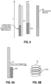
- the schematic can be interpreted either as a single antenna with different portions, or two separate antennas which are juxtaposed end-to-end and simultaneously excited during transmit, while only the lower antenna is active during receive.
- FIG. 6A is an example of separate antennas juxtaposed side by side. In transmit mode the entire length 37 in FIG. 6 , or the longer antenna as shown at 37B in FIG. 6A , is used to transmit RF pulses, whereas in receive mode only the lower part of the antenna, i.e., the receiver section shown at 37A of FIG.
- Pulse shaping is a standard NMR technique that includes adjusting the amplitude and phase of the RF pulses at a given frequency to ensure they do not degrade magnetization in regions to be sampled by RF pulses at other frequencies.
- the lower third of the RF antenna is used to receive the spin-echo signals whereas the entire antenna is used to transmit 90° and 180° RF pulses.
- the measurement starts at the extreme left of FIG. 7 at longitudinal position 70 with a measurement made at a first frequency f1 and thus in a measurement region 62 during receiving RF signals induced by NMR phenomena.
- Tm the instrument moves from position 70 to the position 71A.
- the position of 71A is located at a longitudinal distance from the first position 70 equal to v ⁇ Tm.
- the measurement region 62 annotated with f1 indicates the formation region from which the received spin-echo signals were acquired during the first measurement.
- the order of frequencies does not necessarily have to be monotonically increasing or decreasing.
- the measurement region does not move substantially beyond the initial excitation region for a particular transmitter antenna length 37.
- a pulse sequence e.g., a Carr-Purcell-Meiboom-Gill (CPMG) pulse sequence with 5000 spin echoes (caused by 5000 180° RF pulses following an initial 90° RF excitation pulse) is acquired using an echo spacing TE of 0.2 ⁇ 10-1 s.
- CPMG Carr-Purcell-Meiboom-Gill
- a set of CPMG sequences can be operated after the first main CPMG sequence having fewer spin echoes and a plurality of, e.g., 10 short wait time (e.g., 0.02 s) measurement sequences each having a relatively small number of spin echoes (e.g., 20).
- These sets of CPMG sequences are sometimes referred to as bursts or trainlets, and the present disclosure includes potentially choosing the measurement cycle to include these bursts and any other plurality of pulses.
- NMR spin-echo well logging measurements are typically acquired as phase alternated pairs (i.e., the phases of the 90° pulses in two phase alternated pair CPMG sequences are shifted by a phase angle of 180° and they are then subtracted from each other) in order to cancel baseline offsets in the CPMG spin echo signals.
- subsequent measurements at the same frequency may be one antenna length apart and could be acquired as phase alternated pairs, or measurements at the different closely spaced frequencies could be acquired with alternating phases and combined.
- the offsets could be accounted for in the data processing (See, Freedman, U.S. Pat. No. 6,838,875 ). The method for removing the offsets is not intended to limit the scope of the present disclosure.
- Certain advanced logging modes on tools may log at or below 0.03 km per hour (100 fph (feet per hour)) on LWD, and at or below 600 fph on wireline. In many cases, it may be useful to perform faster logging, such as 1800 fph or more. Accordingly, the techniques of the present disclosure are direct to improving the acquisition rate of NMR logging tools, such as those with multiple antennae (e.g., coils).
- the present techniques employ transmit and receive control of each of the antenna in an antenna array to solve two problems: 1) prepolarization of the magnets on the NMR tool can be used to fullest effect, and 2) to acquire different patterns of NMR data on each coil to build up an entire suite of data all at one depth location, thus enabling truly fast logging.
- FIG. 8 illustrates a well-logging system 10 that employs the systems and methods of this disclosure.
- the well-logging system 10 may be used to convey a downhole tool 12 through a geological formation 14 via a wellbore 16.
- the downhole tool 12 may be conveyed on a cable 18 via a logging winch system 20.
- the logging winch system 20 is schematically shown in FIG. 8 as a mobile logging winch system carried by a truck, the logging winch system 20 may be substantially fixed (e.g., a long-term installation that is substantially permanent or modular). Any suitable cable 18 for well logging may be used.
- the cable 18 may be spooled and unspooled on a drum 22 and an auxiliary power source 24 may provide energy to the logging winch system 20 and/or the downhole tool 12.
- the downhole tool 12 is described as a wireline downhole tool, it should be appreciated that any suitable conveyance may be used.
- the downhole tool 12 may instead be conveyed as a logging-while-drilling (LWD) tool as part of a bottom hole assembly (BHA) of a drill string, conveyed on a slickline or via coiled tubing, and so forth.
- LWD logging-while-drilling
- BHA bottom hole assembly
- the downhole tool 12 is any suitable measurement tool that obtains NMR logging measurements through depths of the wellbore 16.
- the downhole tool 12 may obtain induction logging measurements in the wellbore 16. These include, for example, the Rt Scanner, AIT, and Thrubit Induction tools by Schlumberger Technology Corporation, but induction logging measurements from other downhole tools by other manufacturers may also be used.
- the downhole tool 12 may provide induction logging measurements 26 to a data processing system 28 via any suitable telemetry (e.g., via electrical signals pulsed through the geological formation 14 or via mud pulse telemetry).
- the data processing system 28 may process the induction logging measurements 26 to identify a conductivity and/or resistivity and dielectric constant at various depths of the geological formation 14 in the wellbore 16.
- the data processing system 28 thus may be any electronic data processing system that can be used to carry out the systems and methods of this disclosure.
- the data processing system 28 may include a processor 30, which may execute instructions stored in memory 32 and/or storage 34.
- the memory 32 and/or the storage 34 of the data processing system 28 may be any suitable article of manufacture that can store the instructions.
- the memory 32 and/or the storage 34 may be ROM memory, random-access memory (RAM), flash memory, an optical storage medium, or a hard disk drive, to name a few examples.
- a display 36 which may be any suitable electronic display, may provide a visualization, a well log, or other indication of properties in the geological formation 14 or the wellbore 16 using the induction logging measurements 26.
- FIG. 9 illustrates an example of a downhole tool 12 that includes an antenna (e.g., coils) array 40 that generally operate to generate NMR data indicative of a composition of a formation.
- the antenna array 40 includes three antennae 42a, 42b, and 42c. In some embodiments, the antenna array 40 may include two or more than three antennae 42.
- each antenna 42 will at least partially overlap with a region 46 of the geological formation 14 and, thus, each antenna 42 will interact with a region 46 at a given time.
- antenna 42a overlaps region 46a
- antenna 42b overlaps region 46b
- antenna 42c overlaps region 46c.
- antenna 42a is interacting with region 46a
- antenna 42b is interacting with region 46b
- antenna 42c is interacting with region 46c.
- the downhole tool 12 moves (e.g., along direction 50) a distance equal to the length 52 of an antenna 42
- antenna 42c is interacting with region 46d
- antenna 42b is interacting with region 46c
- antenna 42a is interacting with region 46b.
- optimization of the control of each antenna 42 of the antenna array 40 may reduce difficulties in downhole NMR acquisition such as pre-polarization the of the magnet(s) 43 on the NMR tool can be used to fullest effect, and fast logging by acquiring different patterns of NMR data on each coil to build up an entire suite of data all at one depth location.
- FIG. 10 is a flow diagram 54 for generating NMR data, in accordance with aspects of the present disclosure.
- the steps illustrated in the flow diagram 54 are performed via signals sent from the data processing system 28 or any suitable processing device.
- the process uses one or more Carr-Purcell-Meiboom-Gill sequences and burst sequences to acquire a suite of NMR data.
- CPMG involves acquiring NMR echoes which give rise to T2-based information at a given wait time (polarization).
- bursts is used to refer to additional CPMG echo trains which are relatively shorter and repeated multiple times to build up signal to noise ratio for intermediate and shorter time constants, which also builds up the T1-based information in the data.
- neither the bursts, nor the main CPMG echo trains are pure CPMGs.
- the bursts or main CPMG echo trains comprise additional echo spacings, such as a diffusion editing method by two long echo spacings at the front of a CPMG, in order to encode diffusion into the NMR suite of data.
- the flow diagram 54 includes generating a first pulse at a first position with a plurality of antennae (process block 56).
- the first pulse may include a single CPMG sequence.
- a second pulse is generated with a first subset of the plurality of antennae (process block 58).
- the second pulse includes a CPMG and two "bursts", as discussed herein. It should be appreciated that this may be useful in generating T2 data.
- a third pulse is generated with a second subset of the plurality of antennae 42 (process block 60).
- the second subset of the plurality of antennae 42 may be fewer than the first subset, or a subset of the first subset.
- the third pulse includes a CPMG and five bursts. It should be appreciated that this may be useful in generating T1/T2 data. Furthermore, it should be appreciated that NMR data is gathered at each step, and the data at each step is combined to produce a suite of NMR data (process block 62).
- the block diagram 64 illustrates time points 70 that represent a position (e.g., along axis 66) of antennae 42 over time (e.g., axis 68) as the antennae move the direction of the arrow 48, which is the direction of logging.
- the six time points 70a, 70b, 70c, 70d, 70e, and 70f each illustrate a respective position of the antennae 42 over a length of time.
- the time difference 72 between each time point 70 are equal, while in other embodiments, the time difference 72 may vary by a mathematical relationship, such as an exponential relationship.
- a different pattern of NMR data is acquired as described herein.
- An antenna 42 that is collecting data is indicated by a filled in box and produces a suit of data every 15.2 cm (6 inches).
- the antenna 42c of time point 70b is not transmitting and receiving data (e.g., OFF).
- the antennae 42 acquires NMR data in accordance with process block 56.
- the antennae 42 acquires NMR data in accordance with process block 58.
- the first subset may be antennae 42a and 42b.
- the antennae 42 acquires NMR data in accordance with process block 60.
- illustrated the second subset may be antenna 42a.
- the data acquired at each time point 70a, 70b, and 70c is combined to generate a suite of NMR data. This process is then be repeated at time points 70d, 70e, and 70f to generate a second suite of NMR data.
- the boxes 76 represent "hole-burned” or “used up hydrogen” regions. During operations, "hole-burned” regions may occur at the fourth positions 64a and 64b, where the hydrogens have already been pulsed and, thus, may provide little to no signal. It is presently recognized that one technique to overcome such difficulties is by placing a time gap during the process of generating the NMR data such that at least a portion of the data from the antenna array 40 are in "fresh", or non-previously pulsed hydrogen regions.
Landscapes
- Physics & Mathematics (AREA)
- Life Sciences & Earth Sciences (AREA)
- Engineering & Computer Science (AREA)
- Geology (AREA)
- General Life Sciences & Earth Sciences (AREA)
- Environmental & Geological Engineering (AREA)
- General Physics & Mathematics (AREA)
- Remote Sensing (AREA)
- Geophysics (AREA)
- High Energy & Nuclear Physics (AREA)
- Geochemistry & Mineralogy (AREA)
- Electromagnetism (AREA)
- Mining & Mineral Resources (AREA)
- Health & Medical Sciences (AREA)
- General Health & Medical Sciences (AREA)
- Immunology (AREA)
- Pathology (AREA)
- Biochemistry (AREA)
- Analytical Chemistry (AREA)
- Chemical & Material Sciences (AREA)
- Fluid Mechanics (AREA)
- Condensed Matter Physics & Semiconductors (AREA)
- Geophysics And Detection Of Objects (AREA)
Claims (7)
- Procédé, comprenant :la génération des données RMN en transmettant et en recevant des impulsions dans la formation géologique (14) à l'aide d'une pluralité d'antennes (42a-c) sur un outil de fond de trou (12), dans lequel chaque antenne (42a-c) a une longueur L et est segmentée en une section émettrice et une section réceptrice, dans lequel la section d'émission est active pendant un mode d'émission et la section de réception est active pendant un mode de réception et dans lequel la section d'émission est électriquement court-circuitée pendant le mode de réception, et dans lequel l'outil de fond de trou (12) est déplacé à une vitesse sensiblement égale à L par seconde et dans lequel, à certains moments, des sous-ensembles de la pluralité d'antennes (42a-c) sont actifs ;dans lequel la génération de données RMN par transmission et réception d'impulsions dans la formation géologique comprend :la génération d'une première séquence d'impulsions à une première position le long d'une formation géologique avec la pluralité d'antennes, dans lequel la première séquence d'impulsions comprend une séquence Carr-Purcell-Meiboom-Gill (CPMG) ;la génération d'une seconde séquence d'impulsions à une seconde position avec un premier sous-ensemble d'antennes de la pluralité d'antennes, dans lequel la seconde séquence d'impulsions comprend la séquence CPMG et une première séquence d'impulsions, dans lequel plusieurs suites d'impulsions plus courtes sont répétées successivement ;la génération d'au moins une troisième séquence d'impulsions à au moins une troisième position avec au moins un second sous-ensemble d'antennes de la pluralité d'antennes, dans lequel la troisième séquence d'impulsions au moins comprend une séquence CPMG et au moins une seconde séquence de rafales ; etla génération d'une suite de données RMN T1 et T2 multidimensionnelles basées au moins en partie sur la première séquence d'impulsions, la deuxième séquence d'impulsions et au moins la troisième séquence d'impulsions.
- Procédé selon la revendication 1, dans lequel un premier sous-ensemble de la pluralité d'antennes comprend deux antennes de la pluralité d'antennes ou une antenne de la pluralité d'antennes.
- Procédé selon la revendication 2, dans lequel un premier sous-ensemble de la pluralité d'antennes comprend deux antennes de la pluralité d'antennes.
- Procédé selon la revendication 3, dans lequel le second sous-ensemble de la pluralité d'antennes comprend une antenne de la pluralité d'antennes.
- Procédé selon la revendication 1, dans lequel la section de l'émetteur est électriquement court-circuitée à l'aide d'un interrupteur.
- Procédé selon la revendication 5, dans lequel le commutateur est un relais à lames ou un relais à semi-conducteurs
- Procédé selon la revendication 5, dans lequel le commutateur est un commutateur MOSFET.
Applications Claiming Priority (3)
| Application Number | Priority Date | Filing Date | Title |
|---|---|---|---|
| US201862729864P | 2018-09-11 | 2018-09-11 | |
| US201862730406P | 2018-09-12 | 2018-09-12 | |
| PCT/US2019/050537 WO2020055957A1 (fr) | 2018-09-11 | 2019-09-11 | Techniques de diagraphie par résonance magnétique nucléaire avec des réseaux d'antennes |
Publications (3)
| Publication Number | Publication Date |
|---|---|
| EP3850404A1 EP3850404A1 (fr) | 2021-07-21 |
| EP3850404A4 EP3850404A4 (fr) | 2022-05-18 |
| EP3850404B1 true EP3850404B1 (fr) | 2025-07-09 |
Family
ID=69777164
Family Applications (1)
| Application Number | Title | Priority Date | Filing Date |
|---|---|---|---|
| EP19859129.9A Active EP3850404B1 (fr) | 2018-09-11 | 2019-09-11 | Techniques de diagraphie par résonance magnétique nucléaire avec des réseaux d'antennes |
Country Status (3)
| Country | Link |
|---|---|
| US (1) | US11346974B2 (fr) |
| EP (1) | EP3850404B1 (fr) |
| WO (1) | WO2020055957A1 (fr) |
Families Citing this family (3)
| Publication number | Priority date | Publication date | Assignee | Title |
|---|---|---|---|---|
| US11891888B2 (en) * | 2021-09-15 | 2024-02-06 | Halliburton Energy Services, Inc. | Measuring formation properties and drilling mud properties using nuclear magnetic resonance in a wellbore |
| CN114858866A (zh) * | 2022-05-25 | 2022-08-05 | 珠海华成电力设计院股份有限公司 | 一种竖向深度土壤电阻率检测装置 |
| CN117189086B (zh) * | 2023-09-05 | 2024-03-01 | 中国科学院地质与地球物理研究所 | 一种相控激励井下核磁共振成像装置与方法 |
Family Cites Families (13)
| Publication number | Priority date | Publication date | Assignee | Title |
|---|---|---|---|---|
| US4710713A (en) | 1986-03-11 | 1987-12-01 | Numar Corporation | Nuclear magnetic resonance sensing apparatus and techniques |
| US6255818B1 (en) | 1998-08-18 | 2001-07-03 | Schlumberger Technology Corporation | Method and apparatus for performing magnetic resonance measurements |
| US6140818A (en) | 1998-10-19 | 2000-10-31 | Schlumberger Technology Corporation | NMR logging tool and method for fast logging |
| NO324200B1 (no) * | 1999-04-19 | 2007-09-10 | Baker Hughes Inc | Kjernemagnetiske resonansmalinger i bronnlogging som benytter en optimalisert refaseregulerende pulssekvens |
| US6525534B2 (en) * | 2001-06-15 | 2003-02-25 | Halliburton Energy Services, Inc. | System and methods for NMR signal processing without phase alternated pair stacking |
| US6838875B2 (en) | 2002-05-10 | 2005-01-04 | Schlumberger Technology Corporation | Processing NMR data in the presence of coherent ringing |
| US6781371B2 (en) * | 2002-09-06 | 2004-08-24 | Schlumberger Technology Corporation | High vertical resolution antennas for NMR logging |
| CN201546719U (zh) | 2009-11-11 | 2010-08-11 | 中国海洋石油总公司 | 聚焦型核磁共振偏心测井探头 |
| SG181897A1 (en) | 2010-06-16 | 2012-07-30 | Halliburton Energy Serv Inc | Nuclear magnetic resonance logging tool having an array of antennas |
| EP3080644A1 (fr) | 2013-12-13 | 2016-10-19 | Halliburton Energy Services, Inc. | Changer un mode de fonctionnement d'un outil de diagraphie rmn |
| US9759832B1 (en) * | 2016-04-18 | 2017-09-12 | Schlumberger Technology Corporation | Apparatus and methods for fast NMR well logging without instrument speed effects |
| US10444397B2 (en) * | 2016-11-29 | 2019-10-15 | Schlumberger Technology Corporation | NMR well logging instrument and method with synthetic apertures |
| CN108519624A (zh) * | 2018-03-08 | 2018-09-11 | 中国石油大学(北京) | 井下三维扫描核磁共振成像仪器射频天线接收方法及装置 |
-
2019
- 2019-09-11 US US17/275,287 patent/US11346974B2/en active Active
- 2019-09-11 WO PCT/US2019/050537 patent/WO2020055957A1/fr not_active Ceased
- 2019-09-11 EP EP19859129.9A patent/EP3850404B1/fr active Active
Also Published As
| Publication number | Publication date |
|---|---|
| US20220043177A1 (en) | 2022-02-10 |
| WO2020055957A1 (fr) | 2020-03-19 |
| US11346974B2 (en) | 2022-05-31 |
| EP3850404A4 (fr) | 2022-05-18 |
| EP3850404A1 (fr) | 2021-07-21 |
Similar Documents
| Publication | Publication Date | Title |
|---|---|---|
| US6531869B1 (en) | Methods and apparatus for measuring flow velocity in a wellbore using NMR and applications using same | |
| US7193414B2 (en) | Downhole NMR processing | |
| US7746069B2 (en) | Method of determining a radial profile of a formation parameter indicative of formation treatment efficiency | |
| US6856132B2 (en) | Method and apparatus for subterranean formation flow imaging | |
| US9097818B2 (en) | Kerogen porosity volume and pore size distribution using NMR | |
| EP2628028B1 (fr) | Outil de résonance magnétique nucléaire à aimants externes | |
| US6559640B2 (en) | NMR apparatus and method utilizing pulsed static magnetic fields | |
| US20080143330A1 (en) | Devices, systems and methods for assessing porous media properties | |
| EP3210049B1 (fr) | Évaluation de formation utilisant une résonance magnétique nucléaire à temps d'attente double | |
| US8076933B2 (en) | Method for determining wettability of an oil reservoir | |
| US10444397B2 (en) | NMR well logging instrument and method with synthetic apertures | |
| US9759832B1 (en) | Apparatus and methods for fast NMR well logging without instrument speed effects | |
| CA2465809C (fr) | Procede et appareil d'imagerie pour ecoulements de formations souterraines | |
| CA2563698A1 (fr) | Utilisation de mesures realisees dans un train d'echos pour la correction d'echos multiples dans un deuxieme train d'echos, permettant d'eviter l'utilisation de paire a alternancede phase dans le deuxieme train | |
| US11346974B2 (en) | Techniques for NMR logging with antenna arrays | |
| WO2015178883A1 (fr) | Capteurs de résonance magnétique nucléaire intégrés dans du ciment | |
| US7301337B2 (en) | Frequency dithering to avoid excitation pulse ringing | |
| NO20230796A1 (en) | Adaptive real-time nuclear magnetic resonance logging for subsurface operations |
Legal Events
| Date | Code | Title | Description |
|---|---|---|---|
| STAA | Information on the status of an ep patent application or granted ep patent |
Free format text: STATUS: THE INTERNATIONAL PUBLICATION HAS BEEN MADE |
|
| PUAI | Public reference made under article 153(3) epc to a published international application that has entered the european phase |
Free format text: ORIGINAL CODE: 0009012 |
|
| STAA | Information on the status of an ep patent application or granted ep patent |
Free format text: STATUS: REQUEST FOR EXAMINATION WAS MADE |
|
| 17P | Request for examination filed |
Effective date: 20210311 |
|
| AK | Designated contracting states |
Kind code of ref document: A1 Designated state(s): AL AT BE BG CH CY CZ DE DK EE ES FI FR GB GR HR HU IE IS IT LI LT LU LV MC MK MT NL NO PL PT RO RS SE SI SK SM TR |
|
| DAV | Request for validation of the european patent (deleted) | ||
| DAX | Request for extension of the european patent (deleted) | ||
| A4 | Supplementary search report drawn up and despatched |
Effective date: 20220421 |
|
| RIC1 | Information provided on ipc code assigned before grant |
Ipc: G01N 24/08 20060101ALN20220413BHEP Ipc: G01V 3/10 20060101ALI20220413BHEP Ipc: G01V 3/28 20060101ALI20220413BHEP Ipc: G01R 33/3415 20060101ALI20220413BHEP Ipc: E21B 47/026 20060101ALI20220413BHEP Ipc: G01V 3/32 20060101AFI20220413BHEP |
|
| STAA | Information on the status of an ep patent application or granted ep patent |
Free format text: STATUS: EXAMINATION IS IN PROGRESS |
|
| 17Q | First examination report despatched |
Effective date: 20240205 |
|
| GRAP | Despatch of communication of intention to grant a patent |
Free format text: ORIGINAL CODE: EPIDOSNIGR1 |
|
| STAA | Information on the status of an ep patent application or granted ep patent |
Free format text: STATUS: GRANT OF PATENT IS INTENDED |
|
| RIC1 | Information provided on ipc code assigned before grant |
Ipc: G01N 24/08 20060101ALN20250122BHEP Ipc: G01V 3/10 20060101ALI20250122BHEP Ipc: G01V 3/28 20060101ALI20250122BHEP Ipc: G01R 33/3415 20060101ALI20250122BHEP Ipc: E21B 47/026 20060101ALI20250122BHEP Ipc: G01V 3/32 20060101AFI20250122BHEP |
|
| INTG | Intention to grant announced |
Effective date: 20250214 |
|
| GRAS | Grant fee paid |
Free format text: ORIGINAL CODE: EPIDOSNIGR3 |
|
| GRAA | (expected) grant |
Free format text: ORIGINAL CODE: 0009210 |
|
| STAA | Information on the status of an ep patent application or granted ep patent |
Free format text: STATUS: THE PATENT HAS BEEN GRANTED |
|
| AK | Designated contracting states |
Kind code of ref document: B1 Designated state(s): AL AT BE BG CH CY CZ DE DK EE ES FI FR GB GR HR HU IE IS IT LI LT LU LV MC MK MT NL NO PL PT RO RS SE SI SK SM TR |
|
| REG | Reference to a national code |
Ref country code: GB Ref legal event code: FG4D |
|
| REG | Reference to a national code |
Ref country code: CH Ref legal event code: EP |
|
| REG | Reference to a national code |
Ref country code: IE Ref legal event code: FG4D |
|
| REG | Reference to a national code |
Ref country code: DE Ref legal event code: R096 Ref document number: 602019072419 Country of ref document: DE |
|
| REG | Reference to a national code |
Ref country code: NL Ref legal event code: MP Effective date: 20250709 |
|
| PG25 | Lapsed in a contracting state [announced via postgrant information from national office to epo] |
Ref country code: PT Free format text: LAPSE BECAUSE OF FAILURE TO SUBMIT A TRANSLATION OF THE DESCRIPTION OR TO PAY THE FEE WITHIN THE PRESCRIBED TIME-LIMIT Effective date: 20251110 |
|
| PG25 | Lapsed in a contracting state [announced via postgrant information from national office to epo] |
Ref country code: NL Free format text: LAPSE BECAUSE OF FAILURE TO SUBMIT A TRANSLATION OF THE DESCRIPTION OR TO PAY THE FEE WITHIN THE PRESCRIBED TIME-LIMIT Effective date: 20250709 |
|
| REG | Reference to a national code |
Ref country code: AT Ref legal event code: MK05 Ref document number: 1812325 Country of ref document: AT Kind code of ref document: T Effective date: 20250709 |
|
| PG25 | Lapsed in a contracting state [announced via postgrant information from national office to epo] |
Ref country code: IS Free format text: LAPSE BECAUSE OF FAILURE TO SUBMIT A TRANSLATION OF THE DESCRIPTION OR TO PAY THE FEE WITHIN THE PRESCRIBED TIME-LIMIT Effective date: 20251109 |
|
| PGFP | Annual fee paid to national office [announced via postgrant information from national office to epo] |
Ref country code: DE Payment date: 20251008 Year of fee payment: 7 |
|
| PGFP | Annual fee paid to national office [announced via postgrant information from national office to epo] |
Ref country code: GB Payment date: 20251007 Year of fee payment: 7 |
|
| PGFP | Annual fee paid to national office [announced via postgrant information from national office to epo] |
Ref country code: NO Payment date: 20251008 Year of fee payment: 7 |
|
| REG | Reference to a national code |
Ref country code: LT Ref legal event code: MG9D |
|
| PG25 | Lapsed in a contracting state [announced via postgrant information from national office to epo] |
Ref country code: AT Free format text: LAPSE BECAUSE OF FAILURE TO SUBMIT A TRANSLATION OF THE DESCRIPTION OR TO PAY THE FEE WITHIN THE PRESCRIBED TIME-LIMIT Effective date: 20250709 |
|
| PG25 | Lapsed in a contracting state [announced via postgrant information from national office to epo] |
Ref country code: FI Free format text: LAPSE BECAUSE OF FAILURE TO SUBMIT A TRANSLATION OF THE DESCRIPTION OR TO PAY THE FEE WITHIN THE PRESCRIBED TIME-LIMIT Effective date: 20250709 |
|
| PG25 | Lapsed in a contracting state [announced via postgrant information from national office to epo] |
Ref country code: HR Free format text: LAPSE BECAUSE OF FAILURE TO SUBMIT A TRANSLATION OF THE DESCRIPTION OR TO PAY THE FEE WITHIN THE PRESCRIBED TIME-LIMIT Effective date: 20250709 |
|
| PG25 | Lapsed in a contracting state [announced via postgrant information from national office to epo] |
Ref country code: GR Free format text: LAPSE BECAUSE OF FAILURE TO SUBMIT A TRANSLATION OF THE DESCRIPTION OR TO PAY THE FEE WITHIN THE PRESCRIBED TIME-LIMIT Effective date: 20251010 |
|
| PG25 | Lapsed in a contracting state [announced via postgrant information from national office to epo] |
Ref country code: SE Free format text: LAPSE BECAUSE OF FAILURE TO SUBMIT A TRANSLATION OF THE DESCRIPTION OR TO PAY THE FEE WITHIN THE PRESCRIBED TIME-LIMIT Effective date: 20250709 |
|
| PG25 | Lapsed in a contracting state [announced via postgrant information from national office to epo] |
Ref country code: LV Free format text: LAPSE BECAUSE OF FAILURE TO SUBMIT A TRANSLATION OF THE DESCRIPTION OR TO PAY THE FEE WITHIN THE PRESCRIBED TIME-LIMIT Effective date: 20250709 |
|
| PG25 | Lapsed in a contracting state [announced via postgrant information from national office to epo] |
Ref country code: PL Free format text: LAPSE BECAUSE OF FAILURE TO SUBMIT A TRANSLATION OF THE DESCRIPTION OR TO PAY THE FEE WITHIN THE PRESCRIBED TIME-LIMIT Effective date: 20250709 Ref country code: BG Free format text: LAPSE BECAUSE OF FAILURE TO SUBMIT A TRANSLATION OF THE DESCRIPTION OR TO PAY THE FEE WITHIN THE PRESCRIBED TIME-LIMIT Effective date: 20250709 |
|
| PG25 | Lapsed in a contracting state [announced via postgrant information from national office to epo] |
Ref country code: RS Free format text: LAPSE BECAUSE OF FAILURE TO SUBMIT A TRANSLATION OF THE DESCRIPTION OR TO PAY THE FEE WITHIN THE PRESCRIBED TIME-LIMIT Effective date: 20251009 |
|
| PG25 | Lapsed in a contracting state [announced via postgrant information from national office to epo] |
Ref country code: ES Free format text: LAPSE BECAUSE OF FAILURE TO SUBMIT A TRANSLATION OF THE DESCRIPTION OR TO PAY THE FEE WITHIN THE PRESCRIBED TIME-LIMIT Effective date: 20250709 |
|
| PG25 | Lapsed in a contracting state [announced via postgrant information from national office to epo] |
Ref country code: RO Free format text: LAPSE BECAUSE OF FAILURE TO SUBMIT A TRANSLATION OF THE DESCRIPTION OR TO PAY THE FEE WITHIN THE PRESCRIBED TIME-LIMIT Effective date: 20250709 |
|
| PG25 | Lapsed in a contracting state [announced via postgrant information from national office to epo] |
Ref country code: SM Free format text: LAPSE BECAUSE OF FAILURE TO SUBMIT A TRANSLATION OF THE DESCRIPTION OR TO PAY THE FEE WITHIN THE PRESCRIBED TIME-LIMIT Effective date: 20250709 |
|
| PG25 | Lapsed in a contracting state [announced via postgrant information from national office to epo] |
Ref country code: DK Free format text: LAPSE BECAUSE OF FAILURE TO SUBMIT A TRANSLATION OF THE DESCRIPTION OR TO PAY THE FEE WITHIN THE PRESCRIBED TIME-LIMIT Effective date: 20250709 |
|
| PG25 | Lapsed in a contracting state [announced via postgrant information from national office to epo] |
Ref country code: IT Free format text: LAPSE BECAUSE OF FAILURE TO SUBMIT A TRANSLATION OF THE DESCRIPTION OR TO PAY THE FEE WITHIN THE PRESCRIBED TIME-LIMIT Effective date: 20250709 |
|
| PG25 | Lapsed in a contracting state [announced via postgrant information from national office to epo] |
Ref country code: CZ Free format text: LAPSE BECAUSE OF FAILURE TO SUBMIT A TRANSLATION OF THE DESCRIPTION OR TO PAY THE FEE WITHIN THE PRESCRIBED TIME-LIMIT Effective date: 20250709 |
|
| PG25 | Lapsed in a contracting state [announced via postgrant information from national office to epo] |
Ref country code: SK Free format text: LAPSE BECAUSE OF FAILURE TO SUBMIT A TRANSLATION OF THE DESCRIPTION OR TO PAY THE FEE WITHIN THE PRESCRIBED TIME-LIMIT Effective date: 20250709 Ref country code: EE Free format text: LAPSE BECAUSE OF FAILURE TO SUBMIT A TRANSLATION OF THE DESCRIPTION OR TO PAY THE FEE WITHIN THE PRESCRIBED TIME-LIMIT Effective date: 20250709 |
|
| REG | Reference to a national code |
Ref country code: CH Ref legal event code: H13 Free format text: ST27 STATUS EVENT CODE: U-0-0-H10-H13 (AS PROVIDED BY THE NATIONAL OFFICE) Effective date: 20260504 |
|
| PLBE | No opposition filed within time limit |
Free format text: ORIGINAL CODE: 0009261 |
|
| STAA | Information on the status of an ep patent application or granted ep patent |
Free format text: STATUS: NO OPPOSITION FILED WITHIN TIME LIMIT |