EP3850916B1 - Système de luminaire permettant de déterminer des informations météorologiques - Google Patents
Système de luminaire permettant de déterminer des informations météorologiques Download PDFInfo
- Publication number
- EP3850916B1 EP3850916B1 EP19768804.7A EP19768804A EP3850916B1 EP 3850916 B1 EP3850916 B1 EP 3850916B1 EP 19768804 A EP19768804 A EP 19768804A EP 3850916 B1 EP3850916 B1 EP 3850916B1
- Authority
- EP
- European Patent Office
- Prior art keywords
- light sources
- light
- state
- optical receiver
- luminaire system
- Prior art date
- Legal status (The legal status is an assumption and is not a legal conclusion. Google has not performed a legal analysis and makes no representation as to the accuracy of the status listed.)
- Active
Links
Images




Classifications
-
- H—ELECTRICITY
- H05—ELECTRIC TECHNIQUES NOT OTHERWISE PROVIDED FOR
- H05B—ELECTRIC HEATING; ELECTRIC LIGHT SOURCES NOT OTHERWISE PROVIDED FOR; CIRCUIT ARRANGEMENTS FOR ELECTRIC LIGHT SOURCES, IN GENERAL
- H05B47/00—Circuit arrangements for operating light sources in general, i.e. where the type of light source is not relevant
- H05B47/10—Controlling the light source
- H05B47/175—Controlling the light source by remote control
-
- F—MECHANICAL ENGINEERING; LIGHTING; HEATING; WEAPONS; BLASTING
- F21—LIGHTING
- F21S—NON-PORTABLE LIGHTING DEVICES; SYSTEMS THEREOF; VEHICLE LIGHTING DEVICES SPECIALLY ADAPTED FOR VEHICLE EXTERIORS
- F21S8/00—Lighting devices intended for fixed installation
- F21S8/08—Lighting devices intended for fixed installation with a standard
- F21S8/085—Lighting devices intended for fixed installation with a standard of high-built type, e.g. street light
- F21S8/086—Lighting devices intended for fixed installation with a standard of high-built type, e.g. street light with lighting device attached sideways of the standard, e.g. for roads and highways
-
- F—MECHANICAL ENGINEERING; LIGHTING; HEATING; WEAPONS; BLASTING
- F21—LIGHTING
- F21V—FUNCTIONAL FEATURES OR DETAILS OF LIGHTING DEVICES OR SYSTEMS THEREOF; STRUCTURAL COMBINATIONS OF LIGHTING DEVICES WITH OTHER ARTICLES, NOT OTHERWISE PROVIDED FOR
- F21V23/00—Arrangement of electric circuit elements in or on lighting devices
- F21V23/04—Arrangement of electric circuit elements in or on lighting devices the elements being switches
- F21V23/0442—Arrangement of electric circuit elements in or on lighting devices the elements being switches activated by means of a sensor, e.g. motion or photodetectors
- F21V23/0464—Arrangement of electric circuit elements in or on lighting devices the elements being switches activated by means of a sensor, e.g. motion or photodetectors the sensor sensing the level of ambient illumination, e.g. dawn or dusk sensors
-
- G—PHYSICS
- G01—MEASURING; TESTING
- G01W—METEOROLOGY
- G01W1/00—Meteorology
- G01W1/14—Rainfall or precipitation gauges
-
- F—MECHANICAL ENGINEERING; LIGHTING; HEATING; WEAPONS; BLASTING
- F21—LIGHTING
- F21W—INDEXING SCHEME ASSOCIATED WITH SUBCLASSES F21K, F21L, F21S and F21V, RELATING TO USES OR APPLICATIONS OF LIGHTING DEVICES OR SYSTEMS
- F21W2131/00—Use or application of lighting devices or systems not provided for in codes F21W2102/00-F21W2121/00
- F21W2131/10—Outdoor lighting
- F21W2131/103—Outdoor lighting of streets or roads
Definitions
- the present invention relates in general to a luminaire system for lighting purposes and for determining weather related information.
- Particular embodiments relate to a luminaire system in the form of a luminaire head or in the form of an outdoor lamp post.
- Lamp posts - also known as street lights, light poles, or street lamps - with a dedicated device having an integrated emitter and receiver for determining weather information are known in the art.
- lamp posts are described in WO 2014/180647 , US 9,900,962 , and WO 2014/133946 .
- WO 2014/180647 A1 discloses a luminaire for road illumination, said luminaire comprising a housing containing a light source provided with optics.
- the luminaire further comprising a sensor unit adapted to measure optical properties of the surrounding of the luminaire and a calculation unit adapted to calculate the parameters for controlling the light output of the luminaire based on the optical properties measured by the sensor unit.
- the sensor unit is adapted to measure specular and diffuse reflection properties of the surrounding of the luminaire.
- US 9 900 962 B1 discloses an illumination system and an illumination method.
- An environmental condition of a position of an illumination apparatus is detected, so as to produce an environmental information.
- a corresponding illumination result prediction model is selected according to a first environmental information.
- An illumination character of an illumination light is adjusted according to the illumination result prediction model and the first environmental information.
- WO 2014/133946 A1 discloses a system including at least one lighting device, e.g., at least one LED luminaire, and a control circuit configured to control a spectral output produced by the at least one lighting device responsive to environmental information about an area illuminated by the at least one lighting device.
- the control circuit may be configured to control a color temperature of the illumination responsive to the environmental information.
- the control circuit may be configured to lower the color temperature of the illumination responsive to the environmental information indicating a level of reflected light and/or a weather condition, such as precipitation, correlated with the presence or likely presence of glare.
- the invention is defined by a luminaire system in accordance with claim 1. Further preferred embodiments are defined in the dependent claims.
- the object of embodiments of the present invention is to provide a luminaire system for lighting purposes, whilst at the same time being capable of performing accurate determination of weather conditions, for example in terms of visibility and/or precipitation conditions and/or a state (e.g. reflectivity) of the surface intended to be illuminated and/or a distance between the light sources and said surface.
- a state e.g. reflectivity
- the present invenlion provides a luminaire system comprising: a support comprising a plurality of light sources for creating a light beam; at least one optical receiver configured for detecting a portion of said light beam which is reflected or back-scattered (e.g. by diffusing sources in the air. such as rain. fog, etc., or by a surface to be illuminated, such as a road surface); a control means operatively connected to said at least one optical receiver for obtaining data related to said detected light beam portion.
- the control means is further configured for determining, based on the obtained data, information related to at least one of: ambient visibility, precipitation, a state of the surface intended to be illuminated by the luminaire system, a distance between the plurality of light sources and said surface.
- the light sources and the at least one optical receiver are integrated in a luminaire system in an improved manner compared to prior art solutions.
- this luminaire system not only allows to provide a light beam for illumination purposes, but also allows to determine weather conditions such as for example visibility conditions (e.g. qualitatively and/or quantitatively) and/or precipitation conditions (e.g. dry, rain, fog, snow) and/or a state of the surface to be illuminated (dry, flooded, covered by ice, by snow, by mud, etc.) and/or a distance between the plurality of light sources and said surface.
- visibility conditions e.g. qualitatively and/or quantitatively
- precipitation conditions e.g. dry, rain, fog, snow
- a state of the surface to be illuminated dry, flooded, covered by ice, by snow, by mud, etc.
- the light beam may be delimited by an irregular conical surface, and may contain light rays in different spectra.
- the light beam may be formed by different sub-beams of light rays, e.g. different sub-beams of light rays in different spectra.
- this luminaire system does not use a dedicated integrated emitter-receiver device for determining weather conditions, but that it can use one or more of the standard light sources already present on the support in existing luminaires, or one or more specific light sources added to an existing support with light sources and chosen for allowing a good detection by the optical receiver.
- the system also allows using as the optical receiver a sensor or receiver for purposes other than mere weather-related purposes. This is especially true when using an image sensor or a camera both for traffic monitoring for example as well as for determining weather conditions.
- the luminaire system may be comprised in a luminaire head, in which case the control means may also be embedded in the luminaire head, may be mounted on top of the luminaire head, e.g. on top of a housing of a luminaire head, and more generally may be provided anywhere in and/or on the luminaire head. It is an advantage that such luminaire system is compact and easy to install, since only a power cable needs to be connected to this luminaire system.
- the control means may be arranged outside of the luminaire head, for example inside a lighting pole of a streetlight system, at a distance of the lighting pole, etc.
- the portion of the light beam which is reflected or back-scattered and received by the optical receiver will be different depending on e.g. diffusing sources in the air, such as rain, fog, etc., the conditions of the surface to be illuminated, etc. More in particular, any characteristics such as the polarization and/or the intensity and/or the color of the light beam may be different depending on the properties of environment through which the light beam passes. These differences will allow deriving information about any one or more of ambient visibility, precipitation, a state of the surface intended to be illuminated by the luminaire system, a distance between the plurality of light sources and said surface.
- the luminaire system comprises a housing accommodating the support and the at least one optical receiver.
- the housing may correspond with the housing of the luminaire head. In that manner a compact integrated system is obtained.
- the optical receiver comprises one or more optical receiving elements, wherein each optical receiving element is configured to measure a light intensity of the detected portion of the light beam.
- the optical receiving elements may be arranged according to a regular pattern, for example an array with at least one row and at least two columns of optical receiving elements.
- the optical receiver comprises a row of optical receiver elements extending along a line, and such that, in the mounted positon of the luminaire system, the light emitted by at least one of the plurality of light sources is received on said line.
- Changes in ambient visibility and/or precipitation and/or changes in a state of a surface to be illuminated and/or changes regarding the distance between said surface and the plurality of light sources, will influence the intensity and/or direction and/or the color and/or the polarization of the light beam which is reflected by diffusing sources and/or said surface.
- intensity and direction changes may be detected, optionally in combination with color and/or polarization changes, allowing to determine information related to any one of the above mentioned conditions.
- the measured intensity may indicate that it has started raining or that a surface is covered with snow.
- the optical receiver comprises a plurality of optical receiving elements arranged across a surface of the optical receiver, depending on said distance, different optical receiving elements will detect the reflected light beam, and the detection performed by the plurality of optical receiving elements will allow determining information about the distance.
- control means is configured to control the plurality of light sources to be subsequently in at least a first state and a second state different from the first state, and to control the at least one optical receiver such that the detection is performed at one or more first moments in time in the first state and at one or more second moments in time in the second state.
- the control means Based on a difference between the detected signals in the first state and in the second state, an accurate indication of the information related to ambient visibility and/or precipitation and/or the state of the surface to be illuminated and/or a distance between the plurality of light sources and said surface, can be obtained. Indeed, in that manner, the influence of external light sources of the environment can be eliminated.
- the first state may correspond to an activated state of at least one of the plurality of light sources
- the second state may correspond to a deactivated state of the at least one of the plurality of light sources.
- the first state may correspond to an activated state of at least one of the plurality of light sources
- the second state may correspond to a dimmed state of the at least one of the plurality of light sources.
- the first state may correspond to a deactivated state of at least one of the plurality of light sources
- a second state may correspond to a dimmed state of the at least one of the plurality of light sources.
- the first state may correspond to a first dimmed state of at least one of the plurality of light sources
- the second state may correspond to a second dimmed state of the at least one of the plurality of light sources, said second dimmed state being different from said first dimmed state.
- the first state may correspond to an activated state (optionally dimmed) of only some of the plurality of light sources
- the second state may correspond to an activated (optionally dimmed) or deactivated state of all of the plurality of light sources.
- the first state may correspond to at least one of the plurality of light sources emitting a first portion of a modulated light beam
- the second state may correspond to the at least one of the plurality of light sources emitting a second portion of a modulated light beam.
- control means is configured to control the plurality of light sources between at least a first state and a second state different from the first state, and to control the at least one optical receiver such that the detection is performed first at one or more first moments in time in the first state, subsequently at one or more second moments in time in the second state, and next at one or more third moments in time again in the first state. This allows to further increase the accuracy.
- control means is configured to activate and deactivate at least one light source of said plurality of light sources, and to control the at least one optical receiver such that the detection is performed at one or more first moments in time when said at least one light source is activated and at one or more second moments in time when said at least one light source is deactivated.
- Based on a difference between the detected signals when the at least one light source is activated and deactivated an accurate indication of the information related to ambient visibility and/or precipitation and/or the state of the surface to be illuminated and/or a distance between the plurality of light sources and said surface, can be obtained. Indeed, in that manner, the influence of external light sources of the environment can be reduced or eliminated.
- control means is further adapted
- control means is configured to control the at least one optical receiver such that the detection is performed both during the first time period and outside of the first time period.
- the control means is configured to control the at least one optical receiver such that the detection is performed both during the first time period and outside of the first time period.
- control means is further adapted
- the control means is configured to control the at least one optical receiver such that the detection is performed during the first and second time periods.
- the first time period may be smaller than 10 ms or even smaller than 1 ms, especially in case of light emitting diodes (LEDs). More generally, the first time period may be relatively small as long as it is sufficient for performing the detection. It is an advantage that LEDs can be activated and deactivated in a fast manner and that an optical receiver has a sufficiently short reactivity time, such that detection can be performed in a manner which is invisible to the human eye. Such detections may be repeated for example 1 to 60 times per hour, 24 hours/day, 7 days/week, while requiring only a limited amount of power. It is noted that the frequency may vary depending on e.g. the weather conditions, and that the detections may also be performed on demand, see further.
- the second time period may be larger than 10 seconds, or larger than 30 seconds, or larger than 1 minute, or larger than 5 minutes, or larger than 1 hour.
- the luminaire system further comprises a drive means for powering said plurality of light sources.
- the control means may be adapted for activating or deactivating or otherwise controlling the drive means, for example for operating the drive means in a modulated or pulsed manner.
- the control means or a portion thereof may be integrated in the same housing as the drive means, or may be added as one or more pluggable modules to the driver housing.
- the drive means and the control means may be separate modules included in separate housings.
- the drive means is adapted for providing a modulated power signal to all or to at least one of the plurality of light sources for creating a modulated light beam or a light beam with a modulated component
- the luminaire system further comprises a demodulator for demodulating a signal obtained from the at least one optical receiver
- the control means is further adapted for extracting said information based on the demodulated signal.
- Any suitable modulation technique may be used, for example pulse-width-modulation (PWM) or amplitude modulation (AM).
- the modulated power signal is a pulse-width modulated (PWM) power signal.
- the demodulator may be provided anywhere in the luminaire system, e.g. in or on the luminaire head, in or on the light pole, or at a location remote from the light pole.
- the modulated power signal will be transmitted and/or reflected and/or scattered in a different manner depending on e.g. the weather conditions, a condition of the road surface, a distance between the road surface and the plurality of light sources, etc.
- the demodulated signal will be different depending on these conditions, and will allow deriving information about those conditions.
- the light source will be in different states which is useful for calibration purposes, and in particular for removing the influence of external light sources.
- control means may be configured to control the plurality of light sources and the at least one optical receiver, such that a detection is performed on demand, e.g. when the weather conditions fulfil certain criteria.
- control means may be configured to receive external data, e.g. weather related data, and to control the plurality of light sources and the at least one optical receiver accordingly.
- the luminaire system may comprise one or more sensors capable of sensing weather related data, and the detection may be performed when the sensed weather data fulfills certain criteria.
- each or at least some of the plurality of light sources comprise a plurality of light emitting elements. It is an advantage of using a plurality of light emitting elements that failure of one of these elements does not necessarily imply failure of the entire light source.
- each or at least some of the plurality of light emitting elements are light emitting diodes. It is an advantage that light emitting diodes (known as LEDs) have a high power efficiency, thus providing a power-efficient illumination system. Another advantage of LEDs is that they can be activated during a very small time period (e.g. in the order of 1 ms or even less). For example, when determining weather conditions during daytime, one or more light sources of the plurality of light sources may be activated during a very short time period which is not visible to the naked eye.
- a very small time period e.g. in the order of 1 ms or even less.
- At least one of the plurality of light sources comprises a laser.
- the advantage of using a laser is that a narrow collimated beam can be obtained, so that the power density is higher.
- a narrow collimated beam such as a laser
- a wider beam such as a LED
- the at least one light source and the at least one optical receiver may be matched to each other in order to improve the detection results. It is noted that it is also possible to use a combination of different types of light sources for the detection.
- the luminaire system further comprises a plurality of optical elements associated with the plurality of light sources.
- These optical elements may be flexible optical elements or rigid optical elements. These optical elements are typically arranged in front of the light sources, and thus also mechanically protect the light sources or light elements. At least one of these optical elements may be shaped to spread or diffuse the light being emitted into a relatively wide beam. At least one of these optical elements may be shaped so as to direct the light beam being emitted into a relatively narrow beam. By orienting the relatively narrow beam in an appropriate direction the detection by the optical receiver can be improved.
- the optical elements comprise lenses, collimators, reflectors, diffusers, or any combination thereof.
- the optical elements comprise lenses.
- the plurality of light sources may be an array of LEDs arranged on a PCB, and an array of lenses may be integrated in one integral lens plate which is arranged over the array of LEDs.
- the array of lenses may be an array of the same lenses or different lenses. For example, a majority of the lenses may be shaped to spread or diffuse the light being emitted into a relatively wide beam, whilst a minority of the lenses may be shaped so as to direct the light beam being emitted into a relatively narrow beam.
- control means is further configured to control the plurality of light sources and/or the at least one optical receiver based on the determined information.
- the control means may change a state of the plurality of light sources in case of a certain degree of fog and/or in case the determined visibility is lower than a certain threshold value.
- one or more light sources of the plurality of light sources may be activated or deactivated or dimmed, the shape of the light beam may be changed, the color or color temperature of at least a portion of the light beam may be changed, the intensity of at least a portion of the light beam may be changed, etc.
- the at least one optical receiver may be controlled such that the frequency of the detection is varied based on the determined information.
- the support is or comprises a printed circuit board (PCB).
- the housing of the luminaire head may form the common support for the plurality of light sources.
- two PCB's may be provided each containing one or more of the plurality of light sources, and the two PCB's may be mounted on the housing or on a common heat sink.
- the at least one optical receiver is arranged at a predefined distance from the plurality of light sources. This allows an optical shield to be placed between the light sources and the optical receiver.
- the plurality of light sources and the optical receiver may be arranged on the same support or on a different support.
- the at least one optical receiver is arranged at a predefined distance from the support. This allows thermal and supply voltage decoupling of the light sources and the optical receiver. This also allows an optical shield to be placed between the support and the optical receiver.
- the luminaire system further comprises a receiver optical element associated with the at least one optical receiver, e.g. a receiver lens.
- the receiver optical element may be adapted to make the receiver receptive to only a narrow region.
- the receiver lens may have an angular opening of less than 60°, less than 50°, less than 40° or even less than 10°.
- the receiver lens may be configured to have a wide angular opening, e.g. between 100° and 180°.
- the receiver optical element is preferably arranged and/or oriented for receiving reflected and/or back-scattered light emitted by at least one of the light sources, e.g. a LED light source or a LASER light source.
- the receiver optical element may have a first portion for guiding visible light to a first region of the at least one optical receiver, and a second portion for guiding the reflected or back scattered light to a second region of the at least one optical receiver.
- the first portion and the second portion may be lens portions having a different curvature.
- the first region occupies a major portion of the at least one optical receiver, for example in the range from 80% to 95% of the surface area of the at least one optical receiver.
- the second region occupies a minor portion of the at least one optical receiver, for example in the range from 5% to 20% of the surface area of the at least one optical receiver.
- the second portion may be located in the center of the receiver optical element, or near an edge, or may be a peripheral portion of the receiver optical element.
- the plurality of light sources comprises at least one first light source adapted for generating light having a first spectrum, and at least one second light source adapted for generating light having a second spectrum different from the first spectrum.
- the at least one optical receiver may be sensitive to only the first spectrum, or to only the second spectrum, or to both the first and the second spectrum.
- the at least one optical receiver may comprise a first optical receiver and a second optical receiver having a different sensitivity than the first optical receiver.
- the second spectrum has light components in one or more of the following bands: the ultra-violet (UV) band, the visible spectrum band, the near-infra-red (NIR) band, and the infra-red (IR) band, wherein said light components contain in one or more of said bands at least 5% of the total power of said light components.
- UV ultra-violet
- NIR near-infra-red
- IR infra-red
- the second light source is a laser, or a pulsed laser.
- the luminaire system further comprises a separate feeding means for powering said at least one optical receiver.
- the drive means may be used to power both the plurality of light sources and the optical receiver.
- the at least one optical receiver comprises a photodiode, and/or an array of photo diodes, and/or an image sensor and/or a camera (e.g. a camera including an image sensor).
- the optical receiver is an image sensor
- the optical receiver comprises a plurality of optical receiver elements in the form of pixel sensors. It is an advantage of luminaire systems with a more advanced optical receiver, e.g. an image sensor, that it not only allows to illuminate a scene and allows to determine weather conditions, but also allows to capture real images or even video at a frame rate in the range from 2 Hz to 50 Hz. Such a luminaire system can be used for example to monitor traffic and/or parking conditions in addition to illuminating and determining weather conditions.
- the at least one optical receiver comprises a first and a second optical receiver
- the first and second optical receiver may be different, and may be any one of the types mentioned above.
- the camera may comprise a 2D- image camera, and/or a 3D-image camera, and/or a time-of-flight (TOF) camera, and/or a stereo-vision-camera, and/or an infra-red (IR) camera, and/or a near-infrared (NIR) camera, and/or a camera capable of detecting both visible light and infrared light.
- TOF time-of-flight
- IR infra-red
- NIR near-infrared
- IR or NIR light it can also be used during the daytime without illuminating the environment. It is a particular advantage of using modulated NIR or IR light that it can be used to differentiate between radiation emitted by the sun (as a slowly varying component, for example typically having frequency components lower than 10 Hz) and the modulated light (as a rapidly varying component, for example having frequency components higher than 100 Hz or higher than 1 kHz). In this way, e.g. weather conditions can be reliably determined, despite the presence of sun light.
- control means may be located in, on or near the luminaire head and/or at a remote location, e.g. in a remote server or in a segment controller controlling a plurality of luminaire heads.
- the control means may comprise different control portions (e.g. distinct controllers) which do not necessarily have to be at the same location, e.g. some calculations may be done locally in the luminaire head and other calculations may be done in a remote server. For example controlling the drive means may be done locally, whilst the processing of the obtained data may be done remotely.
- One or more control portions may be integrated in the same housing as the drive means or may be added as one or more pluggable modules to the driver housing. Alternatively, the drive means and the one or more control portions may be separate modules included in separate housings.
- control means is adapted for determining said information based on a spatial analysis of image information obtained from the camera and/or the image sensor.
- control means is adapted for determining said information based on spectral analysis of image information obtained from the camera and/or the image sensor, for example based on color information.
- the luminaire system further comprises a memory operatively connected to the control means, and the control means is adapted for storing data received from the at least one optical receiver at different moments in time, and/or for storing data processed by the control means and/or for storing reference data and/or for storing calibration data, and is further adapted for determining said information based on a correlation, e.g. a temporal correlation of said stored data.
- a correlation e.g. a temporal correlation of said stored data.
- the luminaire system further comprises wired or wireless or optical communication means for communicating with other systems, such as vehicle systems, other luminaire systems, mobile devices, sensor systems, etc., and/or for communicating with a remote server, and the control means is further adapted for transmitting the determined information or data (e.g. unprocessed data) obtained from the at least one optical receiver through the communications means.
- the luminaire system may be part of a larger system, allowing for example gathering weather information by a plurality of luminaire systems positioned at many different locations, thereby allowing accurate determination of weather conditions over a large region, without having to install dedicated devices.
- the luminaire system may be operatively connected to and adapted for transmitting the determined information or data to unmanned/autonomous vehicles, such as autonomous cars, thereby allowing the vehicles to adapt e.g. their speed and/or their headlamp in consequence.
- unmanned/autonomous vehicles such as autonomous cars
- control means is further adapted for receiving information from at least one other luminaire system and/or from a remote device, e.g. a remote server, a vehicle, etc., and the control means is configured to further control the plurality of light sources and/or the at least one optical receiver based on the information received via the communication means.
- a communication system allows the control means of a certain luminaire to change the light emitted by the plurality of light sources (e.g. by activating, deactivating, dimming, changing of the shape of the light distribution, changing of the color or color temperature of the emitted light, etc.) based not only on information from its own (local) optical receiver, but also based on information obtained e.g.
- the decision to change the light emitted by the plurality of light sources may for example be based on majority voting or any other suitable decision scheme. Examples of similar possible control techniques are described in Belgian patent application BE 2018/5172 in the name of the applicant.
- a remote server decides when to change the light emitted by the plurality of light sources for individual luminaires or for a plurality of luminaires based on information obtained from said plurality of luminaires.
- the control means may be configured to only activate the optical receiver of a luminaire in the event that predetermined information, such as predetermined weather information, is received. Further, the control means may be configured to determine, based on received weather information, whether the performed detection by the optical receiver is accurate. This may allow determining when an optical receiver is faulty.
- the luminaire system further comprises a housing accommodating said support and said at least one optical receiver; which housing may be adapted for preventing a direct optical path between the plurality of light sources and the at least one optical receiver. In this way crosstalk caused by direct light entering the optical receiver can be avoided or reduced.
- the housing comprises a cavity accommodating said at least one optical receiver. It is an advantage of this embodiment that a discrete light shield can be avoided, since the cavity walls may act as an optical shield.
- the housing further comprises a light shield arranged between the plurality of light sources and the at least one optical receiver.
- the light shield may be a metal sheet.
- the luminaire system is a luminaire head.
- the support and the optical receiver are incorporated inside the luminaire head. It is advantageous to embed both the support with the light sources and the optical receiver in the luminaire head (as opposed to somewhere in the pole), that such a luminaire head can be provided as a single module which can be produced and tested as a single entity, and in case of failure can be easily and rapidly replaced as a whole.
- the luminaire system is a subsystem of a lamp pole, the lamp pole comprising a luminaire head accommodating at least said support and said at least one optical receiver, the lamp pole further comprising a support pole for supporting said luminaire head.
- This system can be used as a streetlight, for example.
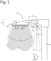
- FIG 1 schematically illustrates an exemplary embodiment of a luminaire system 23.
- the luminaire system comprises a support 24 comprising a plurality of light sources 6 for creating a light beam 4, which is directed downwardly in Figure 1 .
- optical elements 5 such as lenses are provided to guide the light emitted by the plurality of light sources 6.
- the optical elements 5 may be integrated in a plate.
- the luminaire system 23 further comprises at least one optical receiver 2 configured for detecting a portion 11 of the light beam 4 which is reflected or back-scattered by diffusing sources 33, such as e.g.
- Characteristics of this reflected or back-scattered light 11 are indicative of weather conditions, in particular visibility and/or precipitation (e.g. snow, rain, fog, etc.). As explained in detail below with respect to figure 7 , the characteristics of this reflected or back-scattered light 11 may also be indicative for the state of the surface (e.g. covered with snow, covered with water, etc.) and for the distance between the plurality of light sources 6 and the surface.
- the luminaire system 23 further comprises a control means 20 (not shown in Figure 1 but see Figure 6 ).
- the control means 20 is operatively connected (wired or wirelessly) to said at least one optical receiver 2 for obtaining data related to said detected light portion 11, and is configured for determining information related to ambient visibility and/or related to precipitation and/or related to a state of the surface to be illuminated, and/or related to the distance between the plurality of light sources and the surface, based on the obtained data.
- the control means 20 may be further configured to control the plurality of light sources 6 and/or the at least one optical receiver 2, based on the determined information. For example, if it is determined that visibility is below a certain threshold value, for example in case of fog, the light sources 6 may be activated (or "switched on"), even during the day. In other cases, the light sources 6 may be dimmed, e.g. to improve visibility. Also, the light sources 6 may be individually controlled so as to change the light distribution, or the position of the optical elements 5 relative to the light sources 6 may be changed to change the light distribution. For example, the light rays may be cut off at high angles to avoid glare in case of fog, e.g.
- the light sources may be deactivated (or "switched off") during a short time period, for improving the determination. Also, in some embodiments, the frequency of the detection may be changed based on the determined information.
- the control means 20 may be located partially or fully in, on or near the luminaire head and/or partially or fully at a remote location, e.g. in a remote server or in a segment controller controlling a plurality of luminaire heads.
- the control means may comprise different control portions (e.g. distinct controllers) which do not necessarily have to be at the same location.
- the control means 20 may be split e.g. as follows: an embedded control and processing means to synchronize an emitter/receiver and to compute local e.g. weather condition evaluation, and a separate controller (internal/external) to decide on lighting and/or optical receiver operating conditions in response to the determined information.
- control means may control one or more switches (not shown) arranged for providing power from an external supply (not shown in Figure 1 but see Figure 6 ) to the light sources, for example by opening or closing these switches.
- the luminaire system 23 may further comprise a drive means 3 for powering said plurality of light sources 6.
- the drive means may be arranged inside the luminaire head and/or may be mounted in the pole.
- the drive means 3 may also be used to provide power to the optical receiver 2.
- the support 24 may be a printed circuit board, or another kind of holder for holding the plurality of light sources 6.
- the at least one optical receiver 2 is arranged at a predefined distance d from the support 24.
- the distance d may be at least 2 cm or at least 5 cm or at least 10 cm. It is an advantage that the optical receiver 2, e.g. an optical sensor or image sensor is not mounted on the support 24, which allows for a thermal decoupling. However, in other embodiments the optical receiver 2 and the light sources 6 may share a common support.
- the luminaire system 23 may further comprise a housing accommodating said support 24 and said at least one optical receiver 2.
- the housing may have the form of a luminaire head.
- the housing is adapted for preventing a direct optical path between the plurality of light sources 6 and the at least one optical receiver 2.
- the housing comprises a cavity accommodating the at least one optical receiver 2.
- the walls of the cavity may be sized and shaped appropriately such that no direct light path exists between the light sources 6 and the optical receiver 2.
- a light shield 26, for example in the form of a metal plate 26, may be physically arranged between the light sources 6 and the optical receiver 2, for example about halfway between the support 24 and the optical receiver 2.
- Such a metal plate 26 not only blocks direct light but also advantageously reduces electrical interference (EMC, EMI).
- the luminaire head comprises said support 24 and said at least one optical receiver 2 and optionally also said control means 20 or a portion thereof.
- the control means 20 may be embedded in the luminaire head and/or may be mounted on a housing of the luminaire head, e.g. on top of the housing.
- the luminaire system 23 may be a lamp post (also known as street light, light pole, street lamp) comprising a pole 8 and a luminaire head, the luminaire head comprising said support 24 and said at least one optical receiver 2.
- the pole 8 comprises the control means 20 or a portion thereof.
- the control means 20 may also be arranged in the he luminaire head and/or may be mounted on a housing of the luminaire head, e.g. on top of the housing. In both cases, however, the control means 20 is operatively connected to the plurality of light sources 6 and to the at least one optical receiver 2.
- each or at least some of the plurality of light sources 6 comprise a plurality of light emitting elements (not shown).
- the light sources 6 may be driven jointly or individually.
- the light emitting elements may be connected in series, or in parallel, or combinations thereof, for example as two or more parallel chains, each chain comprising a plurality of elements.
- each or at least some of the plurality of light emitting elements are light emitting diodes, known as LEDs. These elements offer the advantage of having a high power efficiency. LEDs are preferably driven by the drive means 3.
- the drive means 3 may have an input connected to a mains supply (not shown), and an output connected to the support 24 via a cable 9.
- the drive means 3 may be an AC to DC convertor providing a predefined or configurable supply voltage, or may comprise one or more current sources adapted for providing one or more predefined or configurable supply currents.
- the drive means 3 may be a separate unit, or may be an integrated driver directly provided on the support 24.
- the luminaire system 23 may further comprise a plurality of optical elements 5, associated with the plurality of light sources 6.
- the optical element can for example be made e.g. from optical silicone or from polycarbonate or from Polymethylmethacrylate (PMMA).
- PMMA Polymethylmethacrylate
- the support contains seven rows of light sources 6 and each row may contain a plurality of light sources, but of course the invention is not limited thereto, and more than seven or less than seven light sources 6 may also be used.
- the optical elements 5 may be adapted for diffusing the light rays emitted by the individual light sources 6, thereby creating the light beam 4 having an angle ⁇ .
- the angle ⁇ may be an angle in the range from about 30° to about 90°.
- the luminaire system 23 further comprises a receiver optical element 1, e.g. a receiver lens, associated with the at least one optical receiver 2.
- the receiver optical element 1 is preferably adapted for guiding a relatively narrow beam 11 defined by an angle ⁇ towards the optical receiver 2.
- the angle ⁇ may be an angle smaller than 20°.
- the receiver optical element 1 is adapted for guiding a relative wide beam, e.g. with an angle ⁇ between 100° and 180°.
- Figure 2 shows a view on a portion of a variant of the luminaire system 23 of Figure 1 .
- a portion of a luminaire system 23' in the form of a luminaire head comprising a support 24, e.g. a PCB, comprising a plurality of light sources 6.
- the luminaire system of Figure 2 comprises at least two different types of light sources: at least one first light source 6 adapted for generating light having a first spectrum, and at least one second light source 12 adapted for generating light having a second spectrum different from the first spectrum.
- the second spectrum may for example have light components in the infra-red (IR) band and/or in the near-infra-red (NIR) band and/or in the ultra-violet (UV) band.
- the second light source 12 may also be a laser or a pulsed laser.
- the optical element 13, e.g. a lens element, which may be optionally arranged in front of the at least one second light source 12 may be the same as the optical elements 5 arranged in front of the at least one first light source 6, or may be different.
- the optical element 13 is adapted for guiding the light emitted by the second light source 12 into a relatively narrow beam, for example having an opening angle ⁇ in the range from about 20° to about 40°.
- the optical element 13 is adapted for guiding a relative wide beam, e.g. with an angle ⁇ between 100° and 180°.
- Figure 3 illustrates a typical sensitivity diagram of a semiconductor image sensor (e.g. implemented in CMOS technology) for different wavelengths.
- CMOS image sensor is sensitive not only to visible light (having wavelengths from about 390 to about 700 nm), but also to UV light and near infrared light.
- Embodiments of the present invention may use for example a second light source 12 emitting at least 5% of its power in the NIR range, and may use an optical receiver 2 sensitive in the NIR range, and the control means 20 may be adapted for determining weather conditions based on characteristics of the reflected or back-scattered NIR light received by said receiver 2. It is an advantage that the human eye is not sensitive to the NIR light, thus this light does not distract for example pedestrians or drivers.
- the optical receiver may be sensitive to visible light (having wavelengths from about 390 nm to about 700 nm) and/or may be sensitive to NIR light (having wavelengths from about 700 nm to about 900 nm), and/or may be sensitive to IR light (having wavelengths from about 900 nm to about 1 mm), and/or may be sensitive to UV light (having wavelengths from about 100 nm to 400 nm).
- light is meant an electromagnetic wave having wavelengths in the range from about 10 nm to about 1 mm.
- Figure 4 schematically illustrates a specific example of an optical receiver 2 and receiver optical element 1 as may be used in embodiments of a luminaire system 23, 23' according to the present invention.
- the optical receiver 2 comprises an image sensor 14 having a pixel array 15 with a plurality of pixels 32.
- the image sensor 14 may be part of a digital camera, which typically further comprises readout circuitry, and may further comprise an image compressor, etc.
- the image sensor may for example be part of a HD camera or of a megapixel camera.
- the HD camera may have a resolution of at least 1280x720 pixels or at least 1920 x 1080 pixels and a frame rate of at least 25 or 30 Hz.
- the megapixel camera may have a resolution of at least 1280x720 pixels or at least 1920 x 1080 pixels and a frame rate of at least 3 Hz or at least 5 Hz.
- cameras or image sensors may be used, for example a 2D- image camera, or a 3D-image camera, or a time-of-light (TOF) camera, or a stereo-vision-camera, or an infra-red (IR) camera, or a near-infrared (NIR) camera, or a camera capable of detecting both visible light and infrared light, etc.
- TOF time-of-light
- IR infra-red
- NIR near-infrared
- a receiver optical element 1 e.g. a lens is arranged in front of the pixel array 15 for guiding incident light towards the pixel array 15.
- the angle ⁇ may be a value in the range from about 20° to about 150°.
- Figure 5 schematically illustrates a variant of the optical receiver and receiver lens arrangement shown in Figure 4 , where the optical element 1, e.g. a lens, associated with the image sensor 14 has a first portion 18 for guiding visible light for capturing visible image information to a first region 16 of the image sensor 14, and where the lens 1 has a second portion 19 for guiding reflected or back scattered light to a second region 17 of the image sensor 14.
- the first portion 18 occupies a major portion of the lens area, for example at least 80%, while the second portion 19 occupies only a minor portion of the lens area, for example at most 20%.
- the first region 16 occupies a major portion of the pixel array 15, for example at least 80%, while the second region 17 occupies only a minor portion 17 of the pixel array 15.
- the second portion 19 is arranged in the center of the lens 1, but that is not required. In an alternative embodiment, the second lens portion 19 is arranged off-center, for example at an edge or near the periphery of the lens 1.
- the second portion 19 preferably has another curvature than the first portion 18, and more in particular a smaller radius of curvature in order to focus the reflected or back scattered light to the second region 17. This will allow making the second region 17 smaller, whilst maintaining a good accuracy.
- the second lens portion 19 defines an angle ⁇ for example in the range from about 20° to about 40°. The angle ⁇ may be the same as in Figure 4 .
- FIG. 6 shows an exemplary hardware block diagram of a luminaire system 23 according to the present invention.
- the luminaire system 23 comprises a plurality of light sources 6a, 6b, and at least one optical receiver 2, e.g. two optical receivers, and a control means 20.
- the plurality of light sources 6a, 6b may be mounted on a support 24, for example a PCB.
- the control means 20 may be a programmable device such as a programmable processor or a programmable microcontroller with internal and/or external memory, for example volatile memory (RAM) and non-volatile memory (e.g. ROM or EPROM of FLASH).
- RAM volatile memory
- non-volatile memory e.g. ROM or EPROM of FLASH.
- the non-volatile memory may comprise computer executable instructions for determining weather related information, based on information obtained from the optical receiver 2, e.g. light sensor, or NIR sensor or image sensor.
- the control means 20 is operatively connected to the optical receiver 2 in order to obtain data indicative of characteristics, for example an amplitude or a power spectrum of a light portion 11 which is reflected or back-scattered by e.g. particles 33 acting as diffusing sources or by the surface to be illuminated, but originating from one or more of the light sources 6a, 6b.
- This data may be received for all optical receiver elements (e.g. pixels of an image sensor) of the at least one optical receiver 2.
- the light sources 6a, 6b may be activated or deactivated by means of one or more switches (not shown) or by means of a drive means 3.
- the drive means 3 may provide one or more predefined or controllable voltages and/or may provide one or more predefined or controllable currents.
- the drive means 3 may be controlled by the control means 20, for example based on the determined weather condition, and/or based on information received from a remote device, e.g. a remote server 28, and/or based on information obtained from other luminaire systems 27, for example neighboring lamp poles.
- the luminaire system 23 may optionally comprise a separate feeding means 34 for powering or controlling the at least one optical receiver 2. Alternatively the drive means 3 may be used.
- the luminaire system comprises at least two optical receivers: a first optical receiver having a first sensitivity spectrum, and a second optical receiver having a second sensitivity spectrum different from the first sensitivity spectrum.
- the luminaire system 23 may further comprise wired or wireless or optical communication means 29 operatively connected to the control means 20, and adapted for communicating with one or more other luminaire systems 27, and/or for communicating with a remote server 28.
- the control means 20 may be further adapted for transmitting the determined information or for transmitting the data, for example unprocessed data obtained from the at least one optical receiver 2, for example light sensor data or NIR sensor data or image or video stream data, through the communications means 29.
- the control means 20 may be further adapted for receiving information from at least one other luminaire system 27, for example from a neighboring lamp post, and/or from the remote device 28 such as a remote server, and may be configured to control the plurality of light sources 6, for example to activate (e.g. turn ON) or deactivate (e.g. turn OFF) or dim or change the shape of the light distribution or change the color or color temperature of the emitted light, based on the information received via the communication means 29.
- control means may apply a majority voting technique in order to determine whether or not to activate or deactivate or dim or otherwise control the light sources 6 and/or the at least one optical receiver 2.
- control means 20 may be configured to only activate the optical receiver 2 of a luminaire in the event that predetermined information, such as predetermined weather information, is received. Further, the control means 20 may be configured to determine, based on received weather information, whether a detection by the at least one optical receiver 2 is accurate.
- the control means 20 may be configured to control the light sources 6 to be subsequently in at least a first state and a second state different from the first state, and to control the optical receiver 2 such that the detection is performed at one or more first moments in time in the first state and at one or more second moments in time in the second state.
- the first state may correspond to an activated state of at least one of the light sources 6, and the second state may correspond to a deactivated state of the at least one of the light sources 6.
- the first state may correspond to an activated state of at least one of the light sources 6, and the second state may correspond to a dimmed state of the at least one of the light sources 6.
- the first state may correspond to a deactivated state of at least one of the light sources 6, and a second state may correspond to a dimmed state of the at least one of the light sources 6.
- the first state may correspond to a first dimmed state of at least one of the light sources 6, and a second state may correspond to a second dimmed state of the at least one of the light sources 6, said second dimmed state being different from the first dimmed state.
- the first state may correspond to an activated (optionally dimmed) state of some of the light sources 6, and the second state may correspond to an activated (optionally dimmed) or deactivated state of all of the light sources 6.
- the first state may correspond to at least one of the light sources 6 emitting a first portion of a modulated light beam
- the second state may correspond to the at least one of the light sources 6 emitting a second portion of a modulated light beam.
- control means 20 is configured to control the light sources 6 between at least a first state and a second state different from the first state, and to control the at least one optical receiver such that the detection is performed first at one or more first moments in time in the first state, subsequently at one or more second moments in time in the second state, and next at one or more third moments in time again in the first state. This allows to further increase the accuracy.
- control means 20 is further adapted for repeatedly activating (during the day) or deactivating (during the night) at least one of the plurality of light sources 6 during a first time period smaller than 100 ms, or smaller than 10 ms, or even smaller than 1 ms, and for deactivating (during the day) or activating (during the night) said at least one light source 6 during a second time period longer than 900 ms, for example longer than 30 seconds or longer than 5 minutes.
- a second time period longer than 900 ms, for example longer than 30 seconds or longer than 5 minutes.
- the weather-related information may then be determined based on detection signals received both during the first and second time period such that the influence of external light sources can be removed.
- the drive means 3 may be adapted to provide a modulated power signal to all or to at least one of the plurality of light sources 6 for creating a modulated light beam or a light beam with a modulated component.
- the luminaire system would then further comprise a demodulator for demodulating the signal received by the at least one optical receiver 2, and the control means 20 would be further adapted to extract said information based on the demodulated signal.
- the demodulator may be a hardware component, or may be partly or fully implemented in the control means 20, for example in software.
- the demodulator may be present in the luminaire head but also in another location such as a remote server.
- this embodiment corresponds with the example given above where the first state corresponds to at least one of the light sources 6 emitting a first portion of a modulated light beam, and the second state corresponds to the at least one of the light sources 6 emitting a second portion of a modulated light beam.
- the modulated power signal provided by the drive means 3 is a pulse-width modulated (PWM) power signal.
- PWM pulse-width modulated
- FIG 7 illustrates schematically another exemplary embodiment of a luminaire system 23 of the invention.
- the luminaire system 23 comprises a support 24 comprising a plurality of light sources 6 for creating a light beam which is directed downwardly.
- the luminaire system 23 further comprises at least one optical receiver 2 configured for detecting a portion of the light beam which is reflected or back-scattered by diffusing sources 33 or by a surface S. Characteristics of this reflected or back-scattered light are indicative of weather conditions, in particular visibility and/or precipitation (e.g. snow, rain, fog, etc.), and/or of the state of the surface (e.g. covered with snow, covered with water, etc.) and/or of the distance H between the plurality of light sources 6 and the surface.
- the luminaire system 23 further comprises a control means (not shown in Figure 7 but see Figure 6 ) operatively connected (wired or wirelessly) to said at least one optical receiver 2 for obtaining data related to said detected light portion.
- the optical receiver 2 comprises a plurality of optical receiving elements 32, e.g. corresponding with the pixels of an image sensor, wherein each optical receiving element 32 is configured to measure a light intensity of the detected portion of the light beam within a predetermined spectrum or within a plurality of predetermined spectra.
- the optical receiving elements 32 may be arranged according to a regular pattern, for example an array with at least one row and at least two columns of optical receiving elements 32.
- the optical receiver comprises a row of optical receiver elements 32 extending along a line, and such that, in the mounted positon of the luminaire system, the light emitted by at least one of the plurality of light sources 6 is received on said line.
- a first light ray I1 is reflected on the surface S and the reflected ray O1 is received in a point P1 of the active surface area of the optical receiver 2.
- a second light ray I2 is reflected/back-scattered on diffusing sources 33 and the reflected/back-scattered ray O2 is received in a point P2 of the active surface area of the optical receiver 2.
- the location of point P1, P1', P1" depends on the distance H between the plurality of light sources 6 and the surface S, S', S" where the light is reflected.
- the measurements performed by optical receiver elements 32 which are arranged along a line containing points P1, P1', P1", allow determining said distance H.
- the state of the surface S, S', S" e.g. concrete, bitume, snow, water, etc.
- changes in ambient visibility and/or precipitation and/or changes in a state of a surface to be illuminated and/or changed regarding the distance between said surface and the plurality of light sources will influence the intensity and/or direction of the light beam which is reflected by diffusing sources and/or said surface.
- both intensity and direction changes may be detected, allowing to determine information related to any one of the above mentioned conditions.
- the measured intensity may indicate that it has started raining or that a surface is covered with snow.
- the control means 20 may be further configured to do a calibration upon installation. Also, the control means 20 may be configured to be self-learning, optionally taking into account received information, such as weather information, information about the surface, information about the height of the luminaire, etc.
Landscapes
- Engineering & Computer Science (AREA)
- Life Sciences & Earth Sciences (AREA)
- Environmental & Geological Engineering (AREA)
- General Engineering & Computer Science (AREA)
- Hydrology & Water Resources (AREA)
- Atmospheric Sciences (AREA)
- Biodiversity & Conservation Biology (AREA)
- Ecology (AREA)
- Environmental Sciences (AREA)
- Circuit Arrangement For Electric Light Sources In General (AREA)
- Photometry And Measurement Of Optical Pulse Characteristics (AREA)
Claims (15)
- Système de luminaire (23) comprenant :- un support (24) comprenant une pluralité de sources lumineuses (6) pour créer un faisceau lumineux (4) ;- au moins un récepteur optique (2) configuré pour détecter une partie (11) du faisceau lumineux (4) qui est réfléchie ou rétrodiffusée ;- un moyen de commande (20) relié fonctionnellement audit au moins un récepteur optique (2) pour obtenir des données relatives à ladite partie de faisceau lumineux détectée (11), et configuré pour déterminer, sur la base des données obtenues, des informations relatives à au moins l'un des éléments suivants : la visibilité ambiante, les précipitations, l'état d'une surface destinée à être éclairée par le système de luminaire, la distance entre la pluralité de sources lumineuses et ladite surfacecaractérisé en ce que le moyen de commande (20) est configuré pour commander la pluralité de sources lumineuses (6) pour qu'elles soient ensuite dans au moins un premier état et un second état différent du premier état, et pour commander l'au moins un récepteur optique (2) de sorte que la détection est effectuée à un ou plusieurs premiers moments dans le premier état et à un ou plusieurs seconds moments dans le second état, dans lequel le moyen de commande (20) est configuré pour obtenir les informations sur la base d'une différence entre la détection aux un ou plusieurs premiers moments dans le premier état et la détection aux un ou plusieurs seconds moments dans le second état.
- Système de luminaire (23) selon la revendication 1, comprenant en outre un boîtier accueillant ledit support (24) et ledit au moins un récepteur optique (2).
- Système de luminaire (23) selon la revendication 2, dans lequel le boîtier est conçu pour empêcher un chemin optique direct entre la pluralité de sources lumineuses (6) et l'au moins un récepteur optique (2),
dans lequel, de préférence, le boîtier comprend une cavité (30) accueillant ledit au moins un récepteur optique (2) ou un écran de lumière (26) disposé entre la pluralité de sources lumineuses (6) et l'au moins un récepteur optique (2). - Système de luminaire (23) selon la revendication 1, dans lequel l'un ou plusieurs parmi ce qui suit sont applicables :- le premier état correspond à un état activé d'au moins une de la pluralité de sources lumineuses, et le second état correspond à un état désactivé de l'au moins une de la pluralité de sources lumineuses ;- le premier état correspond à un état activé d'au moins une de la pluralité de sources lumineuses, et le second état correspond à un état atténué de l'au moins une de la pluralité de sources lumineuses ;- le premier état correspond à un état désactivé d'au moins une de la pluralité de sources lumineuses, et le second état correspond à un état atténué de l'au moins une de la pluralité de sources lumineuses ;- le premier état correspond à un état activé de certaines seulement de la pluralité de sources lumineuses, et le second état correspond à un état activé ou désactivé de l'ensemble de la pluralité de sources lumineuses ;- le premier état correspond à au moins une de la pluralité de sources lumineuses émettant une première partie d'un faisceau lumineux modulé, et le second état correspond à l'au moins une de la pluralité de sources lumineuses émettant une seconde partie d'un faisceau lumineux modulé ;- le premier état correspond à un premier état atténué d'au moins une de la pluralité de sources lumineuses, et le second état correspond à un second état atténué de l'au moins une de la pluralité de sources lumineuses, ledit second état atténué étant différent dudit premier état atténué.
- Système de luminaire (23) selon l'une quelconque des revendications précédentes, dans lequel le moyen de commande (20) est en outre conçu pour activer de manière répétée au moins une de la pluralité de sources lumineuses (6, 12) dans le premier état pour émettre un faisceau lumineux (4, 31) pendant une première période de temps inférieure à 100 ms, et pour désactiver ladite au moins une source lumineuse (6, 12) dans le second état pendant une seconde période de temps entre deux premières périodes de temps, ladite seconde période de temps étant supérieure à 900 ms, dans un mode de non-éclairage du système de luminaire ; et/oudans lequel le moyen de commande (20) est en outre conçu pour désactiver de manière répétée au moins une de la pluralité de sources lumineuses (6, 12) dans le premier état pendant une première période de temps inférieure à 100 ms, et pour activer ladite au moins une source lumineuse (6, 12) dans le second état pendant une seconde période de temps entre deux premières périodes de temps, ladite seconde période de temps étant supérieure à 900 ms, dans un mode d'éclairage du système de luminaire ;dans lequel le moyen de commande est configuré pour commander l'au moins un récepteur optique de manière à ce que la détection soit effectuée au cours des première et deuxième périodes.
- Système de luminaire (23) selon l'une quelconque des revendications précédentes, comprenant en outre un moyen de pilotage (3) pour alimenter ladite pluralité de sources lumineuses (6),
dans lequel, de préférence, le moyen de pilotage (3) est conçu pour fournir un signal de puissance modulé, de préférence un signal de puissance modulé en largeur d'impulsion, à toutes les sources lumineuses (6, 12) ou à au moins l'une de la pluralité de celles-ci pour créer un faisceau lumineux modulé ou un faisceau lumineux avec une composante modulée, et le système de luminaire comprend en outre un démodulateur pour démoduler un signal obtenu à partir de l'au moins un récepteur optique (2), et le moyen de commande (20) est en outre conçu pour extraire lesdites informations sur la base du signal démodulé. - Système de luminaire (23) selon l'une quelconque des revendications précédentes, dans lequel chacune ou au moins certaines de la pluralité de sources lumineuses (6) comprennent une pluralité d'éléments émetteurs de lumière et/ou comprennent en outre une pluralité d'éléments optiques (5) associés à la pluralité de sources lumineuses (6) et/oudans lequel le moyen de commande (20) est en outre configuré pour commander la pluralité de sources lumineuses (6) sur la base des informations déterminées et/oudans lequel l'au moins un récepteur optique (2) est disposé à une distance prédéfinie de la pluralité de sources lumineuses (6).
- Système de luminaire (23) selon l'une quelconque des revendications précédentes, dans lequel la pluralité de sources lumineuses (6) comprend au moins une première source lumineuse conçue pour générer une lumière ayant un premier spectre et au moins une deuxième source lumineuse (12) conçue pour générer une lumière ayant un deuxième spectre différent du premier spectre ;
dans lequel, de préférence, le deuxième spectre a des composantes lumineuses dans une ou plusieurs des bandes suivantes : la bande des ultraviolets, la bande du spectre visible, la bande des infrarouges proches et la bande des infrarouges ou dans lequel, de préférence, la deuxième source lumineuse (12) est un laser ou un laser à impulsions. - Système de luminaire (23) selon l'une quelconque des revendications précédentes, comprenant en outre un moyen d'alimentation (34) pour alimenter ledit au moins un récepteur optique (2) et/ou dans lequel l'au moins un récepteur optique (2) comprend une photodiode et/ou un réseau de photodiodes et/ou une caméra et/ou un capteur d'image (14), dans lequel la caméra comprend de préférence une caméra d'image 2D, et/ou une caméra d'image 3D, et/ou une caméra à temps de vol, et/ou une caméra à vision stéréoscopique, et/ou une caméra infrarouge, et/ou une caméra infrarouge proche, et/ou une caméra configurée pour détecter à la fois la lumière visible et la lumière infrarouge.
- Système de luminaire (23) selon la revendication 9, dans lequel l'au moins un récepteur optique (2) comprend une caméra et/ou un capteur d'image (14) ;dans lequel le moyen de commande (20) est conçu pour déterminer lesdites informations sur la base d'une analyse spatiale d'informations d'image obtenues à partir de la caméra et/ou du capteur d'image (14) ; et/oudans lequel le moyen de commande (20) est conçu pour déterminer lesdites informations sur la base d'une analyse spectrale d'informations d'image obtenues à partir de la caméra et/ou du capteur d'image (14).
- Système de luminaire (23) selon l'une quelconque des revendications précédentes,comprenant en outre une mémoire (21) reliée fonctionnellement au moyen de commande (20) ;et dans lequel le moyen de commande (20) est conçu pour stocker des données reçues à partir du récepteur optique (2) à différents moments dans le temps, ou pour stocker des données traitées sur la base desdites données reçues, et est en outre conçu pour déterminer lesdites informations sur la base desdites données stockées et/oucomprenant en outre des moyens de communication filaires, sans fil ou optiques (29) pour communiquer avec d'autres systèmes de luminaires (27) et/ou pour communiquer avec un dispositif distant (28) ;et dans lequel le moyen de commande (20) est en outre conçu pour transmettre les informations déterminées ou des données obtenues à partir de l'au moins un récepteur optique (2) par l'intermédiaire du moyen de communication (29) ; le moyen de commande (20) est de préférence conçu pour recevoir des informations à partir d'au moins un autre système de luminaire (27) et/ou du dispositif distant (28), et configuré en outre pour commander la pluralité de sources lumineuses (6, 12) et/ou l'au moins un récepteur optique sur la base des informations reçues par l'intermédiaire du moyen de communication (29).
- Tête de luminaire (25) comprenant le système de luminaire (23) selon l'une quelconque des revendications précédentes.
- Mât d'éclairage comprenant le système de luminaire (23) selon l'une quelconque des revendications 1 à 11, le mât d'éclairage comprenant :- une tête de luminaire configurée pour accueillir au moins ledit support (24) et ledit au moins un récepteur optique (2), et- un mât de support (8) configuré pour supporter ladite tête de luminaire (25).
- Système de luminaire (23) selon l'une quelconque des revendications 1 à 11, dans lequel le support (24) comprend une carte de circuit imprimé et/ou
dans lequel les informations comprennent des informations sur la distance entre la surface et la pluralité de sources lumineuses, dans lequel le récepteur optique comprend une pluralité d'éléments de réception optique disposés sur une surface du récepteur optique et configurés pour détecter le faisceau lumineux réfléchi, et dans lequel les données obtenues comprennent le faisceau lumineux réfléchi détecté. - Système de luminaire (23) selon l'une quelconque des revendications 1 à 11, 14, comprenant en outre un élément optique récepteur (1) associé à l'au moins un récepteur optique (2), dans lequel l'élément optique récepteur a une première partie pour guider la lumière visible vers une première région de l'au moins un récepteur optique, et une seconde partie pour guider la lumière réfléchie ou rétrodiffusée vers une seconde région de l'au moins un récepteur optique.
Applications Claiming Priority (2)
| Application Number | Priority Date | Filing Date | Title |
|---|---|---|---|
| NL2021612A NL2021612B1 (en) | 2018-09-12 | 2018-09-12 | Luminaire system for determining weather related information |
| PCT/EP2019/074380 WO2020053342A1 (fr) | 2018-09-12 | 2019-09-12 | Système de luminaire permettant de déterminer des informations météorologiques |
Publications (2)
| Publication Number | Publication Date |
|---|---|
| EP3850916A1 EP3850916A1 (fr) | 2021-07-21 |
| EP3850916B1 true EP3850916B1 (fr) | 2024-07-24 |
Family
ID=66286845
Family Applications (1)
| Application Number | Title | Priority Date | Filing Date |
|---|---|---|---|
| EP19768804.7A Active EP3850916B1 (fr) | 2018-09-12 | 2019-09-12 | Système de luminaire permettant de déterminer des informations météorologiques |
Country Status (5)
| Country | Link |
|---|---|
| EP (1) | EP3850916B1 (fr) |
| ES (1) | ES2986886T3 (fr) |
| NL (1) | NL2021612B1 (fr) |
| PT (1) | PT3850916T (fr) |
| WO (1) | WO2020053342A1 (fr) |
Families Citing this family (15)
| Publication number | Priority date | Publication date | Assignee | Title |
|---|---|---|---|---|
| NL2022954B1 (en) | 2019-04-16 | 2020-10-26 | Schreder Sa | Receptacle for Lighting Equipment |
| NL2026201B1 (en) | 2020-08-03 | 2022-04-08 | Schreder Sa | Receptacle assembly with gasket |
| DE102020129841A1 (de) * | 2020-11-12 | 2022-05-12 | Siteco Gmbh | Straßenleuchte mit integriertem Feuchtigkeitssensor |
| NL2027061B1 (en) | 2020-12-07 | 2022-07-07 | Schreder Sa | Network system using fog computing |
| NL2027062B1 (en) | 2020-12-07 | 2022-07-07 | Schreder Sa | Self-learning system with sensors |
| NL2027116B1 (en) | 2020-12-15 | 2022-07-08 | Schreder Sa | Luminaire head with a removable cap |
| NL2028884B1 (en) | 2021-07-29 | 2023-02-02 | Schreder Iluminacao Sa | Edge device configuration system and method |
| WO2023131408A1 (fr) | 2022-01-07 | 2023-07-13 | Schreder S.A. | Ensemble réceptacle avec jupe de protection |
| AU2024265495A1 (en) | 2023-05-02 | 2025-12-18 | Schreder Iluminaçao Sa | Luminaire system for determining environmental characteristics |
| NL2034751B1 (en) | 2023-05-02 | 2024-11-14 | Schreder Iluminacao Sa | Luminaire system for determining environmental characteristics |
| NL2035258B1 (en) | 2023-07-04 | 2025-01-10 | Schreder Iluminacao Sa | System with image capturing means |
| AU2024288921A1 (en) | 2023-07-04 | 2026-02-19 | Schréder Iluminaçao Sa | System with image capturing means |
| NL2035257B1 (en) | 2023-07-04 | 2025-01-10 | Schreder Iluminacao Sa | Method for optimization of sensor network placement |
| NL2035871B1 (en) | 2023-09-25 | 2025-04-01 | Schreder Sa | Luminaire with dongle |
| WO2025157722A1 (fr) * | 2024-01-25 | 2025-07-31 | Signify Holding B.V. | Système de capteur, agencement de capteur et procédé de détection d'état lié aux conditions météorologiques |
Family Cites Families (7)
| Publication number | Priority date | Publication date | Assignee | Title |
|---|---|---|---|---|
| JP5058631B2 (ja) * | 2006-03-03 | 2012-10-24 | 日本電気株式会社 | 光源装置、表示装置、端末装置及びそれらの制御方法 |
| US8362707B2 (en) * | 2008-12-12 | 2013-01-29 | Cirrus Logic, Inc. | Light emitting diode based lighting system with time division ambient light feedback response |
| US8547036B2 (en) * | 2011-11-20 | 2013-10-01 | Available For Licensing | Solid state light system with broadband optical communication capability |
| US11304276B2 (en) * | 2013-02-26 | 2022-04-12 | Ideal Industries Lighting Llc | Glare-reactive lighting apparatus |
| WO2014180647A1 (fr) * | 2013-05-07 | 2014-11-13 | Koninklijke Philips N.V. | Luminaire d'éclairage de route à capteur |
| JP6468609B2 (ja) * | 2014-02-26 | 2019-02-13 | フィリップス ライティング ホールディング ビー ヴィ | 光の反射に基づく検出 |
| CN108076553B (zh) * | 2016-11-10 | 2020-08-11 | 光宝电子(广州)有限公司 | 照明系统及其照明方法 |
-
2018
- 2018-09-12 NL NL2021612A patent/NL2021612B1/en active
-
2019
- 2019-09-12 EP EP19768804.7A patent/EP3850916B1/fr active Active
- 2019-09-12 PT PT197688047T patent/PT3850916T/pt unknown
- 2019-09-12 ES ES19768804T patent/ES2986886T3/es active Active
- 2019-09-12 WO PCT/EP2019/074380 patent/WO2020053342A1/fr not_active Ceased
Also Published As
| Publication number | Publication date |
|---|---|
| ES2986886T3 (es) | 2024-11-13 |
| WO2020053342A8 (fr) | 2020-11-05 |
| WO2020053342A1 (fr) | 2020-03-19 |
| PT3850916T (pt) | 2024-10-01 |
| EP3850916A1 (fr) | 2021-07-21 |
| NL2021612B1 (en) | 2020-05-06 |
Similar Documents
| Publication | Publication Date | Title |
|---|---|---|
| EP3850916B1 (fr) | Système de luminaire permettant de déterminer des informations météorologiques | |
| EP3111134B1 (fr) | Détection à base de réflexion de la lumière | |
| KR100874461B1 (ko) | 차량의 외부 조명 제어 장치 및 차량의 자동 제어 장치 | |
| US10628696B2 (en) | Imaging device, object detector and mobile device control system | |
| US9519841B2 (en) | Attached matter detector and vehicle equipment control apparatus | |
| CA2691141C (fr) | Systeme d'eclairage avec fonctions de gestion de trafic | |
| US7855376B2 (en) | Lighting system and method for illuminating and detecting object | |
| KR100682523B1 (ko) | 반도체 광 센서들을 가진 차량 기기 제어장치 | |
| US7015944B2 (en) | Device for improving visibility in vehicles | |
| US11143749B2 (en) | Object detection system and method | |
| US20140043478A1 (en) | Security camera assembly | |
| KR20010005899A (ko) | 차량 전조등 자동감광 제어장치 | |
| KR20140041617A (ko) | 차량용 카메라 시스템 | |
| US20130235203A1 (en) | Indicia identifying system | |
| KR101943195B1 (ko) | 지능형 조명 제어장치 및 방법 | |
| JP6555569B2 (ja) | 画像処理装置、移動体機器制御システム及び画像処理用プログラム | |
| KR101707146B1 (ko) | 전류제어방식을 이용한 적응적 조명장치 및 그에 대한 제어방법 | |
| JP2015169567A (ja) | 付着物検出装置、移動体機器制御システム及び付着物検出用プログラム | |
| CA2354093C (fr) | Systeme de commande concu pour diminuer automatiquement l'intensite lumineuse des phares de vehicules | |
| MXPA99008906A (en) | Control system to automatically dim vehicle head lamps |
Legal Events
| Date | Code | Title | Description |
|---|---|---|---|
| STAA | Information on the status of an ep patent application or granted ep patent |
Free format text: STATUS: UNKNOWN |
|
| STAA | Information on the status of an ep patent application or granted ep patent |
Free format text: STATUS: THE INTERNATIONAL PUBLICATION HAS BEEN MADE |
|
| PUAI | Public reference made under article 153(3) epc to a published international application that has entered the european phase |
Free format text: ORIGINAL CODE: 0009012 |
|
| STAA | Information on the status of an ep patent application or granted ep patent |
Free format text: STATUS: REQUEST FOR EXAMINATION WAS MADE |
|
| 17P | Request for examination filed |
Effective date: 20210305 |
|
| AK | Designated contracting states |
Kind code of ref document: A1 Designated state(s): AL AT BE BG CH CY CZ DE DK EE ES FI FR GB GR HR HU IE IS IT LI LT LU LV MC MK MT NL NO PL PT RO RS SE SI SK SM TR |
|
| DAV | Request for validation of the european patent (deleted) | ||
| DAX | Request for extension of the european patent (deleted) | ||
| STAA | Information on the status of an ep patent application or granted ep patent |
Free format text: STATUS: EXAMINATION IS IN PROGRESS |
|
| 17Q | First examination report despatched |
Effective date: 20230103 |
|
| GRAP | Despatch of communication of intention to grant a patent |
Free format text: ORIGINAL CODE: EPIDOSNIGR1 |
|
| STAA | Information on the status of an ep patent application or granted ep patent |
Free format text: STATUS: GRANT OF PATENT IS INTENDED |
|
| RIC1 | Information provided on ipc code assigned before grant |
Ipc: H05B 47/175 20200101ALI20240202BHEP Ipc: G01W 1/14 20060101ALI20240202BHEP Ipc: F21W 131/103 20060101ALI20240202BHEP Ipc: F21V 23/04 20060101ALI20240202BHEP Ipc: F21S 8/08 20060101ALI20240202BHEP Ipc: H05B 45/00 20200101AFI20240202BHEP |
|
| INTG | Intention to grant announced |
Effective date: 20240228 |
|
| GRAS | Grant fee paid |
Free format text: ORIGINAL CODE: EPIDOSNIGR3 |
|
| GRAA | (expected) grant |
Free format text: ORIGINAL CODE: 0009210 |
|
| STAA | Information on the status of an ep patent application or granted ep patent |
Free format text: STATUS: THE PATENT HAS BEEN GRANTED |
|
| AK | Designated contracting states |
Kind code of ref document: B1 Designated state(s): AL AT BE BG CH CY CZ DE DK EE ES FI FR GB GR HR HU IE IS IT LI LT LU LV MC MK MT NL NO PL PT RO RS SE SI SK SM TR |
|
| REG | Reference to a national code |
Ref country code: GB Ref legal event code: FG4D |
|
| REG | Reference to a national code |
Ref country code: CH Ref legal event code: EP |
|
| REG | Reference to a national code |
Ref country code: DE Ref legal event code: R096 Ref document number: 602019055753 Country of ref document: DE |
|
| P01 | Opt-out of the competence of the unified patent court (upc) registered |
Free format text: CASE NUMBER: APP_40325/2024 Effective date: 20240707 |
|
| REG | Reference to a national code |
Ref country code: IE Ref legal event code: FG4D |
|
| REG | Reference to a national code |
Ref country code: PT Ref legal event code: SC4A Ref document number: 3850916 Country of ref document: PT Date of ref document: 20241001 Kind code of ref document: T Free format text: AVAILABILITY OF NATIONAL TRANSLATION Effective date: 20240924 |
|
| REG | Reference to a national code |
Ref country code: NL Ref legal event code: FP |
|
| REG | Reference to a national code |
Ref country code: LT Ref legal event code: MG9D |
|
| REG | Reference to a national code |
Ref country code: ES Ref legal event code: FG2A Ref document number: 2986886 Country of ref document: ES Kind code of ref document: T3 Effective date: 20241113 |
|
| REG | Reference to a national code |
Ref country code: AT Ref legal event code: MK05 Ref document number: 1707482 Country of ref document: AT Kind code of ref document: T Effective date: 20240724 |
|
| PG25 | Lapsed in a contracting state [announced via postgrant information from national office to epo] |
Ref country code: NO Free format text: LAPSE BECAUSE OF FAILURE TO SUBMIT A TRANSLATION OF THE DESCRIPTION OR TO PAY THE FEE WITHIN THE PRESCRIBED TIME-LIMIT Effective date: 20241024 |
|
| PG25 | Lapsed in a contracting state [announced via postgrant information from national office to epo] |
Ref country code: GR Free format text: LAPSE BECAUSE OF FAILURE TO SUBMIT A TRANSLATION OF THE DESCRIPTION OR TO PAY THE FEE WITHIN THE PRESCRIBED TIME-LIMIT Effective date: 20241025 Ref country code: FI Free format text: LAPSE BECAUSE OF FAILURE TO SUBMIT A TRANSLATION OF THE DESCRIPTION OR TO PAY THE FEE WITHIN THE PRESCRIBED TIME-LIMIT Effective date: 20240724 |
|
| PG25 | Lapsed in a contracting state [announced via postgrant information from national office to epo] |
Ref country code: BG Free format text: LAPSE BECAUSE OF FAILURE TO SUBMIT A TRANSLATION OF THE DESCRIPTION OR TO PAY THE FEE WITHIN THE PRESCRIBED TIME-LIMIT Effective date: 20240724 |
|
| PG25 | Lapsed in a contracting state [announced via postgrant information from national office to epo] |
Ref country code: LV Free format text: LAPSE BECAUSE OF FAILURE TO SUBMIT A TRANSLATION OF THE DESCRIPTION OR TO PAY THE FEE WITHIN THE PRESCRIBED TIME-LIMIT Effective date: 20240724 |
|
| PG25 | Lapsed in a contracting state [announced via postgrant information from national office to epo] |
Ref country code: IS Free format text: LAPSE BECAUSE OF FAILURE TO SUBMIT A TRANSLATION OF THE DESCRIPTION OR TO PAY THE FEE WITHIN THE PRESCRIBED TIME-LIMIT Effective date: 20241124 Ref country code: AT Free format text: LAPSE BECAUSE OF FAILURE TO SUBMIT A TRANSLATION OF THE DESCRIPTION OR TO PAY THE FEE WITHIN THE PRESCRIBED TIME-LIMIT Effective date: 20240724 |
|
| PG25 | Lapsed in a contracting state [announced via postgrant information from national office to epo] |
Ref country code: HR Free format text: LAPSE BECAUSE OF FAILURE TO SUBMIT A TRANSLATION OF THE DESCRIPTION OR TO PAY THE FEE WITHIN THE PRESCRIBED TIME-LIMIT Effective date: 20240724 |
|
| PG25 | Lapsed in a contracting state [announced via postgrant information from national office to epo] |
Ref country code: RS Free format text: LAPSE BECAUSE OF FAILURE TO SUBMIT A TRANSLATION OF THE DESCRIPTION OR TO PAY THE FEE WITHIN THE PRESCRIBED TIME-LIMIT Effective date: 20241024 |
|
| PG25 | Lapsed in a contracting state [announced via postgrant information from national office to epo] |
Ref country code: RS Free format text: LAPSE BECAUSE OF FAILURE TO SUBMIT A TRANSLATION OF THE DESCRIPTION OR TO PAY THE FEE WITHIN THE PRESCRIBED TIME-LIMIT Effective date: 20241024 Ref country code: NO Free format text: LAPSE BECAUSE OF FAILURE TO SUBMIT A TRANSLATION OF THE DESCRIPTION OR TO PAY THE FEE WITHIN THE PRESCRIBED TIME-LIMIT Effective date: 20241024 Ref country code: LV Free format text: LAPSE BECAUSE OF FAILURE TO SUBMIT A TRANSLATION OF THE DESCRIPTION OR TO PAY THE FEE WITHIN THE PRESCRIBED TIME-LIMIT Effective date: 20240724 Ref country code: IS Free format text: LAPSE BECAUSE OF FAILURE TO SUBMIT A TRANSLATION OF THE DESCRIPTION OR TO PAY THE FEE WITHIN THE PRESCRIBED TIME-LIMIT Effective date: 20241124 Ref country code: HR Free format text: LAPSE BECAUSE OF FAILURE TO SUBMIT A TRANSLATION OF THE DESCRIPTION OR TO PAY THE FEE WITHIN THE PRESCRIBED TIME-LIMIT Effective date: 20240724 Ref country code: GR Free format text: LAPSE BECAUSE OF FAILURE TO SUBMIT A TRANSLATION OF THE DESCRIPTION OR TO PAY THE FEE WITHIN THE PRESCRIBED TIME-LIMIT Effective date: 20241025 Ref country code: FI Free format text: LAPSE BECAUSE OF FAILURE TO SUBMIT A TRANSLATION OF THE DESCRIPTION OR TO PAY THE FEE WITHIN THE PRESCRIBED TIME-LIMIT Effective date: 20240724 Ref country code: BG Free format text: LAPSE BECAUSE OF FAILURE TO SUBMIT A TRANSLATION OF THE DESCRIPTION OR TO PAY THE FEE WITHIN THE PRESCRIBED TIME-LIMIT Effective date: 20240724 Ref country code: AT Free format text: LAPSE BECAUSE OF FAILURE TO SUBMIT A TRANSLATION OF THE DESCRIPTION OR TO PAY THE FEE WITHIN THE PRESCRIBED TIME-LIMIT Effective date: 20240724 |
|
| PG25 | Lapsed in a contracting state [announced via postgrant information from national office to epo] |
Ref country code: RO Free format text: LAPSE BECAUSE OF FAILURE TO SUBMIT A TRANSLATION OF THE DESCRIPTION OR TO PAY THE FEE WITHIN THE PRESCRIBED TIME-LIMIT Effective date: 20240724 Ref country code: DK Free format text: LAPSE BECAUSE OF FAILURE TO SUBMIT A TRANSLATION OF THE DESCRIPTION OR TO PAY THE FEE WITHIN THE PRESCRIBED TIME-LIMIT Effective date: 20240724 Ref country code: SM Free format text: LAPSE BECAUSE OF FAILURE TO SUBMIT A TRANSLATION OF THE DESCRIPTION OR TO PAY THE FEE WITHIN THE PRESCRIBED TIME-LIMIT Effective date: 20240724 |
|
| PG25 | Lapsed in a contracting state [announced via postgrant information from national office to epo] |
Ref country code: MC Free format text: LAPSE BECAUSE OF FAILURE TO SUBMIT A TRANSLATION OF THE DESCRIPTION OR TO PAY THE FEE WITHIN THE PRESCRIBED TIME-LIMIT Effective date: 20240724 Ref country code: EE Free format text: LAPSE BECAUSE OF FAILURE TO SUBMIT A TRANSLATION OF THE DESCRIPTION OR TO PAY THE FEE WITHIN THE PRESCRIBED TIME-LIMIT Effective date: 20240724 |
|
| PG25 | Lapsed in a contracting state [announced via postgrant information from national office to epo] |
Ref country code: CZ Free format text: LAPSE BECAUSE OF FAILURE TO SUBMIT A TRANSLATION OF THE DESCRIPTION OR TO PAY THE FEE WITHIN THE PRESCRIBED TIME-LIMIT Effective date: 20240724 |
|
| REG | Reference to a national code |
Ref country code: DE Ref legal event code: R097 Ref document number: 602019055753 Country of ref document: DE |
|
| PG25 | Lapsed in a contracting state [announced via postgrant information from national office to epo] |
Ref country code: SK Free format text: LAPSE BECAUSE OF FAILURE TO SUBMIT A TRANSLATION OF THE DESCRIPTION OR TO PAY THE FEE WITHIN THE PRESCRIBED TIME-LIMIT Effective date: 20240724 |
|
| REG | Reference to a national code |
Ref country code: CH Ref legal event code: PL |
|
| PG25 | Lapsed in a contracting state [announced via postgrant information from national office to epo] |
Ref country code: LU Free format text: LAPSE BECAUSE OF NON-PAYMENT OF DUE FEES Effective date: 20240912 |
|
| PLBE | No opposition filed within time limit |
Free format text: ORIGINAL CODE: 0009261 |
|
| STAA | Information on the status of an ep patent application or granted ep patent |
Free format text: STATUS: NO OPPOSITION FILED WITHIN TIME LIMIT |
|
| 26N | No opposition filed |
Effective date: 20250425 |
|
| PG25 | Lapsed in a contracting state [announced via postgrant information from national office to epo] |
Ref country code: IT Free format text: LAPSE BECAUSE OF NON-PAYMENT OF DUE FEES Effective date: 20240912 |
|
| PG25 | Lapsed in a contracting state [announced via postgrant information from national office to epo] |
Ref country code: CH Free format text: LAPSE BECAUSE OF NON-PAYMENT OF DUE FEES Effective date: 20240930 |
|
| PG25 | Lapsed in a contracting state [announced via postgrant information from national office to epo] |
Ref country code: IE Free format text: LAPSE BECAUSE OF NON-PAYMENT OF DUE FEES Effective date: 20240912 |
|
| PG25 | Lapsed in a contracting state [announced via postgrant information from national office to epo] |
Ref country code: SE Free format text: LAPSE BECAUSE OF FAILURE TO SUBMIT A TRANSLATION OF THE DESCRIPTION OR TO PAY THE FEE WITHIN THE PRESCRIBED TIME-LIMIT Effective date: 20240724 |
|
| PGFP | Annual fee paid to national office [announced via postgrant information from national office to epo] |
Ref country code: NL Payment date: 20250820 Year of fee payment: 7 |
|
| PGFP | Annual fee paid to national office [announced via postgrant information from national office to epo] |
Ref country code: PT Payment date: 20250825 Year of fee payment: 7 |
|
| PGFP | Annual fee paid to national office [announced via postgrant information from national office to epo] |
Ref country code: DE Payment date: 20250820 Year of fee payment: 7 |
|
| PGFP | Annual fee paid to national office [announced via postgrant information from national office to epo] |
Ref country code: PL Payment date: 20250826 Year of fee payment: 7 |
|
| PGFP | Annual fee paid to national office [announced via postgrant information from national office to epo] |
Ref country code: BE Payment date: 20250820 Year of fee payment: 7 Ref country code: GB Payment date: 20250822 Year of fee payment: 7 |
|
| PGFP | Annual fee paid to national office [announced via postgrant information from national office to epo] |
Ref country code: FR Payment date: 20250820 Year of fee payment: 7 |
|
| PG25 | Lapsed in a contracting state [announced via postgrant information from national office to epo] |
Ref country code: CY Free format text: LAPSE BECAUSE OF FAILURE TO SUBMIT A TRANSLATION OF THE DESCRIPTION OR TO PAY THE FEE WITHIN THE PRESCRIBED TIME-LIMIT; INVALID AB INITIO Effective date: 20190912 |
|
| PGFP | Annual fee paid to national office [announced via postgrant information from national office to epo] |
Ref country code: ES Payment date: 20251001 Year of fee payment: 7 |
|
| PG25 | Lapsed in a contracting state [announced via postgrant information from national office to epo] |
Ref country code: HU Free format text: LAPSE BECAUSE OF FAILURE TO SUBMIT A TRANSLATION OF THE DESCRIPTION OR TO PAY THE FEE WITHIN THE PRESCRIBED TIME-LIMIT; INVALID AB INITIO Effective date: 20190912 |