EP3850927B1 - Connecteur haute puissance et procédé d'assemblage associé - Google Patents
Connecteur haute puissance et procédé d'assemblage associé Download PDFInfo
- Publication number
- EP3850927B1 EP3850927B1 EP19782728.0A EP19782728A EP3850927B1 EP 3850927 B1 EP3850927 B1 EP 3850927B1 EP 19782728 A EP19782728 A EP 19782728A EP 3850927 B1 EP3850927 B1 EP 3850927B1
- Authority
- EP
- European Patent Office
- Prior art keywords
- locking element
- cover
- connector
- conductive element
- fact
- Prior art date
- Legal status (The legal status is an assumption and is not a legal conclusion. Google has not performed a legal analysis and makes no representation as to the accuracy of the status listed.)
- Active
Links
Images


Classifications
-
- H—ELECTRICITY
- H05—ELECTRIC TECHNIQUES NOT OTHERWISE PROVIDED FOR
- H05K—PRINTED CIRCUITS; CASINGS OR CONSTRUCTIONAL DETAILS OF ELECTRIC APPARATUS; MANUFACTURE OF ASSEMBLAGES OF ELECTRICAL COMPONENTS
- H05K7/00—Constructional details common to different types of electric apparatus
- H05K7/14—Mounting supporting structure in casing or on frame or rack
- H05K7/1422—Printed circuit boards receptacles, e.g. stacked structures, electronic circuit modules or box like frames
- H05K7/1427—Housings
- H05K7/1432—Housings specially adapted for power drive units or power converters
- H05K7/14329—Housings specially adapted for power drive units or power converters specially adapted for the configuration of power bus bars
-
- H—ELECTRICITY
- H05—ELECTRIC TECHNIQUES NOT OTHERWISE PROVIDED FOR
- H05K—PRINTED CIRCUITS; CASINGS OR CONSTRUCTIONAL DETAILS OF ELECTRIC APPARATUS; MANUFACTURE OF ASSEMBLAGES OF ELECTRICAL COMPONENTS
- H05K7/00—Constructional details common to different types of electric apparatus
- H05K7/14—Mounting supporting structure in casing or on frame or rack
- H05K7/1401—Mounting supporting structure in casing or on frame or rack comprising clamping or extracting means
- H05K7/1402—Mounting supporting structure in casing or on frame or rack comprising clamping or extracting means for securing or extracting printed circuit boards
- H05K7/1408—Mounting supporting structure in casing or on frame or rack comprising clamping or extracting means for securing or extracting printed circuit boards by a unique member which latches several boards, e.g. locking bars
-
- Y—GENERAL TAGGING OF NEW TECHNOLOGICAL DEVELOPMENTS; GENERAL TAGGING OF CROSS-SECTIONAL TECHNOLOGIES SPANNING OVER SEVERAL SECTIONS OF THE IPC; TECHNICAL SUBJECTS COVERED BY FORMER USPC CROSS-REFERENCE ART COLLECTIONS [XRACs] AND DIGESTS
- Y02—TECHNOLOGIES OR APPLICATIONS FOR MITIGATION OR ADAPTATION AGAINST CLIMATE CHANGE
- Y02T—CLIMATE CHANGE MITIGATION TECHNOLOGIES RELATED TO TRANSPORTATION
- Y02T10/00—Road transport of goods or passengers
- Y02T10/60—Other road transportation technologies with climate change mitigation effect
- Y02T10/70—Energy storage systems for electromobility, e.g. batteries
Definitions
- the present invention relates to a high power connector, usable in particular as an external connector in DC-DC converters, battery chargers or the like, and to the related assembly method.
- the need is known to manufacture power electrical apparatuses provided with high power connectors accessible from the outside.
- Such power electronic apparatuses generally comprise one or more power or control electronic boards, composed of one or more printed circuits, housed inside a suitable container.
- the container is hermetically sealed using a special cover.
- the container must be provided with a suitable access opening and relative closing means, e.g. with a door. Therefore, the container itself is more complex with inevitably higher production costs.
- the main aim of the present invention is to devise a high power connector and a related assembly method which allow the assembly and electrical connection operations to be simplified.
- Another object of the present invention is to devise a high power connector and a related assembly method which allow overcoming the aforementioned drawbacks of the prior art within a simple, rational, easy, effective to use and affordable solution.
- reference numeral 1 globally indicates a high power connector, installable in particular on a power apparatus.
- the connector 1 according to the invention can be used in the automotive sector, in particular with reference to the production of electronic power apparatuses installed on board electric or hybrid vehicles, such as OBC (On-Board Charger) battery chargers or DC-DC converters.
- OBC On-Board Charger
- the connector 1 can be used on a power electronic apparatus A comprising a container B, at least one power electronic circuit C housed inside the container B, and at least one cover D for closing the container B.
- the connector 1 comprises at least one electricity conductive element 2 of substantially elongated conformation and provided with a first end portion electrically connectable to the power electronic circuit C and with a second end portion provided with at least one electrical connection terminal 3.
- the conductive element 2 is made of a metal material.
- the conductive element 2 is insertable inside a through opening E made on the cover D. After being inserted, the terminal 3 faces outwards and is therefore accessible for the connection of a further connector.
- the connector 1 comprises at least one locking element 4, made of an electrically insulating material, which can be coupled with the conductive element 2 and fixable to the outer surface of the cover D.
- the locking element 4 enables therefore the conductive element 2 to be effectively locked on the cover, in a simple and quick manner.
- the locking element 4 is made of a polymeric material.
- the connector 1 comprises coupling means between the conductive element 2 and the locking element 4.
- the coupling means are composed of coupling means in rotation between the conductive element 2 and the locking element 4 with respect to the longitudinal axis of the conductive element itself.
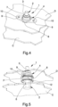
- the locking element 4 comprises at least one housing seat 5, visible in Figure 5 , adapted to house at least partly the second end portion of the conductive element 2, when the locking element 4 is fixed to the outer surface of the cover D.
- the locking element 4 comprises a portion provided with an access opening 6 for the access to the housing seat 5, through which the second end portion of the conductive element 2 can be inserted.
- the portion provided with the access opening 6 is insertable at least partly and to measure inside the through opening E made on the cover D.
- the locking element 4 comprises at least one outlet opening 7 of the terminal 3 of the conductive element 2, when the locking element itself is fixed to the outer surface of the cover D.
- the locking element 4 comprises a body 8 with a substantially cylindrical and tubular conformation provided at one end with the access opening 6 and at an opposite end with the outlet opening 7.
- the end of the body of the locking element 4 provided with the outlet opening 7 has a substantially cylindrical conformation with a cross-section having a diameter decreasing towards the outside.
- the end provided with the outlet opening 7 and the terminal 3 constitute an attachment designed to connect a corresponding connector.
- the shape of the locking element 4 can be adapted and modified according to the particular shape of the through opening E on the cover D or of the specific connector to be connected to the terminal 3.
- the coupling means between the conductive element 2 and the locking element 4 are constituted by polygonal coupling means.
- the coupling means comprise one portion of the conductive element 2 provided with an outer transverse profile of polygonal conformation. Furthermore, the coupling means comprise one portion of the inner surface of the housing seat 5 of the locking element 4 provided with an inner transverse profile of polygonal conformation.
- the outer transverse profile of the conductive element 2 and the inner transverse profile of the housing seat 5 are mutually complementary and coupleable to measure for the locking of the locking element 4 in rotation on the conductive element 2. Specifically, as shown in the illustrations, these profiles can be hexagonal. Different conformations cannot however be ruled out.
- the locking element 4 also comprises fixing means 9, 10 to the cover D.
- Such fixing means 9, 10 comprise at least one portion 9 projecting from the outer surface of the body of the locking element 4 which surface is provided with at least one fixing hole 10.
- the fixing hole 10 is positionable at a respective hole F on the cover D for fixing by means of screws or the like.
- the fixing means 9, 10 comprise a pair of lateral fins 9 projecting from the body of the locking element 4 and opposite to each other. Both lateral fins 9 are provided with respective fixing holes 10.
- the fixing holes 10 are composed of slots. Preferably, these slots 10 are curvilinear.
- the connector 1 comprises sealing means 11, 12 adapted to ensure a perfect sealing between the conductive element 2 and the locking element 4 and between the locking element 4 and the cover D.
- the sealing means 11, 12 comprise at least a first gasket 11 interposed between the outer surface of the conductive element 2 and the inner surface of the housing seat 5 of the locking element 4.
- the first gasket 11 is composed of an o-ring positioned inside a relative circular seat formed at a cylindrical portion of the conductive element 2, in the proximity of the terminal 3.
- the first gasket 11 is positioned in the proximity of the outlet opening 7.
- sealing means 11, 12 comprise at least a second gasket 12 arranged along at least one stretch of the body of the locking element 4.
- the second gasket 12 is adapted to be interposed between the outer surface of the locking element itself and the inner surface of the through opening E of the cover D, when the locking element 4 is fixed to the cover D.
- the method provides for the connection of the first end portion of the conductive element 2 to the power electronic circuit C.
- this connection provides for the fixing of the first end portion of the conductive element 2 to at least one suitable support of the power electronic apparatus A.
- the first end portion of the conductive element 2 can be fixed directly to a printed circuit PCB, to a suitable frame or to a bus bar of the electronic apparatus A.
- the method provides for the positioning of the cover D onto the container B and the positioning of the second end portion of the conductive element 2 inside the through opening E of the cover D.
- the cover D is then fixed to the container B to close the compartment containing the electronics.
- the locking element 4 is positioned at the through opening E with the second end portion of the conductive element 2 arranged inside the housing seat 5 of the locking element 4 and with the terminal 3 projecting from the outlet opening 7 of the locking element itself.
- the positioning of the locking element 4 must be carried out by aligning the slots 10 on the lateral fins 9 of the locking element 4 with the respective holes F on the cover D.
- the method provides for fixing the locking element 4 to the outer surface of the cover D.
- This fixing can be carried out by means of screws or similar threaded means inserted in the slots 10 and locked inside the holes F on the cover D.
- the electronic apparatus A according to the invention can be used in particular in the automotive sector and consists of a power electronic apparatus installed on board electric or hybrid vehicles.
- the electronic device A may consist of an OBC (On-Board Charger) battery charger or a DC-DC converter.
- OBC On-Board Charger
- the electronic apparatus A comprises a container B, at least one power electronic circuit C housed inside the container B, and at least one cover D for closing the container B.
- the electronic apparatus A comprises at least one high power connector 1 similar to the connector 1 described above.
- the first end portion of the conductive element 2 is electrically connected to the power electronic circuit C and the second end portion of the conductive element 2 is inserted inside the through opening E made on the cover D with the terminal 3 facing to the outside.
- the locking element 4 is coupled to the conductive element 2 and is fixed to the outer surface of the cover D.
Landscapes
- Engineering & Computer Science (AREA)
- Microelectronics & Electronic Packaging (AREA)
- Connector Housings Or Holding Contact Members (AREA)
- Details Of Connecting Devices For Male And Female Coupling (AREA)
- Mounting Components In General For Electric Apparatus (AREA)
- Manufacturing Of Electrical Connectors (AREA)
- Connection Or Junction Boxes (AREA)
Claims (14)
- Connecteur haute puissance (1), apte à être installé sur un appareil électronique de puissance (A) comprenant un contenant (B), au moins un circuit électronique de puissance (C) reçu à l'intérieur dudit contenant (B), et au moins un couvercle (D) pour fermer ledit contenant (B),dans lequel ledit connecteur (1) comprend au moins un élément conducteur d'électricité (2) de conformation sensiblement allongée et comportant une première partie d'extrémité apte à être reliée électriquement audit circuit électronique de puissance (C) et une seconde partie d'extrémité comportant au moins une borne de connexion électrique (3), ledit élément conducteur (2) étant apte à être inséré à l'intérieur d'une ouverture traversante (E) pratiquée sur ledit couvercle (D) avec ladite borne (3) orientée vers l'extérieur ;dans lequel ledit connecteur (1) comprend au moins un élément de verrouillage (4) réalisé en un matériau électriquement isolant qui peut être couplé audit élément conducteur (2) et configuré pour être apte à être fixé à la surface extérieure dudit couvercle (D) lorsque ledit couvercle (D) est fixé audit contenant (B),dans lequel ledit connecteur comprend des moyens de couplage entre ledit élément conducteur (2) et ledit élément de verrouillage (4), lesdits moyens de couplage comprenant au moins une partie dudit élément conducteur (2) comportant un profil transversal extérieur de conformation polygonale et au moins une partie de la surface intérieure d'un siège de réception (5) dudit élément de verrouillage (4) comportant un profil transversal intérieur de conformation polygonale, ledit profil transversal extérieur et ledit profil transversal intérieur étant mutuellement complémentaires et conçus pour être couplés de façon à mesurer le verrouillage dudit élément de verrouillage (4) en rotation sur ledit élément conducteur (2) ,dans lequel ledit élément de verrouillage (4) comprend des moyens de fixation (9, 10) audit couvercle (D),caractérisé par le fait que lesdits moyens de fixation (9, 10) comprennent au moins une partie (9) faisant saillie à partir de la surface extérieure dudit élément de verrouillage (4) et comportant au moins un trou de fixation (10), ledit trou de fixation (10) étant apte à être positionné au niveau d'un trou respectif (F) sur ledit couvercle (D) pour une fixation au moyen de vis ou analogues, etdans lequel ledit trou de fixation (10) est en forme de fente.
- Connecteur (1) selon la revendication 1, caractérisé par le fait que lesdits moyens de couplage comprennent des moyens de couplage en rotation entre ledit élément conducteur (2) et ledit élément de verrouillage (4) par rapport à l'axe longitudinal dudit élément conducteur (2).
- Connecteur (1) selon une ou plusieurs des revendications précédentes, caractérisé par le fait que ledit élément de verrouillage (4) comprend au moins un siège de réception (5) conçu pour recevoir au moins partiellement ladite seconde partie d'extrémité de l'élément conducteur (2), lorsque ledit élément de verrouillage (4) est fixé à la surface extérieure du couvercle (D).
- Connecteur (1) selon la revendication 3, caractérisé par le fait que ledit élément de verrouillage (4) comprend une partie comportant une ouverture d'accès (6) audit siège de réception (5).
- Connecteur (1) selon la revendication 4, caractérisé par le fait que ladite partie comportant l'ouverture d'accès (6) est apte à être insérée au moins partiellement à l'intérieur de ladite ouverture traversante (E) sur le couvercle (D).
- Connecteur (1) selon une ou plusieurs des revendications précédentes, caractérisé par le fait que ledit élément de verrouillage (4) comprend au moins une ouverture de sortie (7) de ladite borne (3) de l'élément conducteur (2), lorsque ledit élément de verrouillage (4) est fixé à la surface extérieure du couvercle (D).
- Connecteur (1) selon une ou plusieurs des revendications précédentes, caractérisé par le fait qu'il comprend des moyens d'étanchéité (11, 12).
- Connecteur (1) selon la revendication 7, caractérisé par le fait que lesdits moyens d'étanchéité (11, 12) comprennent au moins un premier joint d'étanchéité (11) interposé entre la surface extérieure dudit élément conducteur (2) et la surface intérieure dudit siège de réception (5) de l'élément de verrouillage (4).
- Connecteur (1) selon une ou plusieurs des revendications 7 et 8, caractérisé par le fait que lesdits moyens d'étanchéité (11, 12) comprennent au moins un second joint d'étanchéité (12) disposé le long d'au moins un tronçon dudit élément de verrouillage (4) et conçu pour être interposé entre la surface extérieure dudit élément de verrouillage (4) et la surface intérieure de ladite ouverture traversante (E) du couvercle (D), lorsque ledit élément de verrouillage (4) est fixé audit couvercle (D).
- Connecteur (1) selon une ou plusieurs des revendications précédentes, caractérisé par le fait que ledit élément conducteur (2) est réalisé en un matériau métallique.
- Connecteur (1) selon une ou plusieurs des revendications précédentes, caractérisé par le fait que ledit élément de verrouillage (4) est réalisé en un matériau polymère.
- Procédé d'assemblage d'un connecteur haute puissance (1) selon une ou plusieurs des revendications 1 à 11, caractérisé par le fait qu'il comprend au moins les étapes suivantes :- connecter ladite première partie d'extrémité de l'élément conducteur (2) audit circuit électronique de puissance (C) ;- positionner ledit couvercle (D) sur ledit contenant (B) avec ladite seconde partie d'extrémité dudit élément conducteur (2) insérée à l'intérieur de ladite ouverture traversante (E) du couvercle (D) ;- positionner ledit élément de verrouillage (4) sur ladite ouverture traversante (E), avec ladite seconde partie d'extrémité de l'élément conducteur (2) disposée à l'intérieur dudit siège de réception (5) de l'élément de verrouillage et avec ladite borne (3) faisant saillie à partir de ladite ouverture de sortie (7) de l'élément de verrouillage ;- fixer ledit élément de verrouillage (4) à la surface extérieure dudit couvercle (D).
- Procédé selon la revendication 12, caractérisé par le fait que ladite étape de connexion comprend la fixation de ladite première partie d'extrémité de l'élément conducteur (2) à au moins un support dudit appareil électronique de puissance (A) .
- Appareil électronique de puissance (A) pour véhicules, comprenant un contenant (B), au moins un circuit électronique de puissance (C) reçu à l'intérieur dudit contenant (B), et au moins un couvercle de fermeture (D) dudit contenant (B) comportant au moins une ouverture traversante (E), caractérisé par le fait qu'il comprend au moins un connecteur haute puissance (1) selon une ou plusieurs des revendications 1 à 11, dans lequel ladite première partie d'extrémité de l'élément conducteur (2) est connectée électriquement audit circuit électronique de puissance (C) et ladite seconde partie d'extrémité est insérée à l'intérieur de ladite ouverture traversante (E) pratiquée sur le couvercle (D) avec ladite borne (3) orientée vers l'extérieur, et dans lequel ledit élément de verrouillage (4) est couplé audit élément conducteur (2) et est fixé à la surface extérieure dudit couvercle (D).
Applications Claiming Priority (2)
| Application Number | Priority Date | Filing Date | Title |
|---|---|---|---|
| IT201800008577 | 2018-09-13 | ||
| PCT/IB2019/057640 WO2020053775A1 (fr) | 2018-09-13 | 2019-09-11 | Connecteur haute puissance et procédé d'assemblage associé |
Publications (2)
| Publication Number | Publication Date |
|---|---|
| EP3850927A1 EP3850927A1 (fr) | 2021-07-21 |
| EP3850927B1 true EP3850927B1 (fr) | 2023-08-23 |
Family
ID=64427097
Family Applications (1)
| Application Number | Title | Priority Date | Filing Date |
|---|---|---|---|
| EP19782728.0A Active EP3850927B1 (fr) | 2018-09-13 | 2019-09-11 | Connecteur haute puissance et procédé d'assemblage associé |
Country Status (5)
| Country | Link |
|---|---|
| US (1) | US11653468B2 (fr) |
| EP (1) | EP3850927B1 (fr) |
| JP (1) | JP7546551B2 (fr) |
| CN (1) | CN113039872B (fr) |
| WO (1) | WO2020053775A1 (fr) |
Family Cites Families (19)
| Publication number | Priority date | Publication date | Assignee | Title |
|---|---|---|---|---|
| BE625861A (fr) * | 1961-12-08 | |||
| CH428881A (de) * | 1965-07-16 | 1967-01-31 | Balzers Patent Beteilig Ag | Elektrische Durchführung in der Wand einer Vakuumaufdampfanlage |
| US4174145A (en) * | 1976-12-29 | 1979-11-13 | The United States Of America As Represented By The United States Department Of Energy | High pressure electrical insulated feed thru connector |
| US4840547A (en) * | 1988-08-10 | 1989-06-20 | Tecumseh Products Company | Compressor including protective cap for hermetic terminal |
| US5227587A (en) * | 1991-05-13 | 1993-07-13 | Emerson Electric Co. | Hermetic assembly arrangement for a current conducting pin passing through a housing wall |
| US5308925A (en) * | 1992-06-26 | 1994-05-03 | Emerson Electric Co. | Conductive pin assembly for a machine housing |
| US6509525B2 (en) * | 1998-11-07 | 2003-01-21 | Emerson Electric Co. | Hermetic terminal assembly |
| JP2002276550A (ja) * | 2001-03-14 | 2002-09-25 | Matsushita Electric Ind Co Ltd | 電動機内蔵の圧縮機と外部配線との接続方法、それに用いる接続具、それらを用いた電動機内蔵の圧縮機 |
| US6670074B2 (en) * | 2001-04-23 | 2003-12-30 | Wilson Greatbatch Ltd. | Glass to metal seal |
| US6844502B2 (en) * | 2002-05-16 | 2005-01-18 | Emerson Electric Co. | Hermetically sealed current conducting terminal assembly |
| US6628024B1 (en) * | 2002-07-30 | 2003-09-30 | Honeywell International, Inc. | Hermetically sealed feed-through assembly for gas turbine engine starter generators and related methods |
| FR2979177B1 (fr) * | 2011-08-19 | 2014-05-23 | Valeo Sys Controle Moteur Sas | Bloc de puissance pour onduleur de vehicule electrique |
| US8742255B2 (en) * | 2011-11-30 | 2014-06-03 | Lear Corporation | Housing assembly to enclose and ground an electrical subassembly |
| CN104521075B (zh) * | 2012-05-30 | 2016-11-02 | 德尔福国际业务卢森堡公司 | 用于车辆装置的互连组件以及互连方法 |
| WO2014096881A1 (fr) * | 2012-12-17 | 2014-06-26 | Delphi International Operations Luxembourg S.À.R.L. | Ensemble connecteur électrique à haute puissance |
| JP5606581B1 (ja) | 2013-05-02 | 2014-10-15 | 三菱電機株式会社 | 車両用電源装置 |
| DE102015209279A1 (de) * | 2015-05-21 | 2016-11-24 | Robert Bosch Gmbh | Elektrische Kontaktanordnung |
| JP6458152B2 (ja) * | 2015-08-06 | 2019-01-23 | 日立オートモティブシステムズ株式会社 | Dcdcコンバータ一体型充電器 |
| EP3185406B1 (fr) * | 2015-12-24 | 2018-08-22 | Fico Triad, S.A. | Chargeur embarqué pour véhicules électriques |
-
2019
- 2019-09-11 EP EP19782728.0A patent/EP3850927B1/fr active Active
- 2019-09-11 US US17/275,620 patent/US11653468B2/en active Active
- 2019-09-11 JP JP2021514407A patent/JP7546551B2/ja active Active
- 2019-09-11 CN CN201980073574.2A patent/CN113039872B/zh active Active
- 2019-09-11 WO PCT/IB2019/057640 patent/WO2020053775A1/fr not_active Ceased
Also Published As
| Publication number | Publication date |
|---|---|
| EP3850927A1 (fr) | 2021-07-21 |
| CN113039872B (zh) | 2023-05-23 |
| JP2022512548A (ja) | 2022-02-07 |
| WO2020053775A1 (fr) | 2020-03-19 |
| US11653468B2 (en) | 2023-05-16 |
| CN113039872A (zh) | 2021-06-25 |
| US20220053660A1 (en) | 2022-02-17 |
| JP7546551B2 (ja) | 2024-09-06 |
Similar Documents
| Publication | Publication Date | Title |
|---|---|---|
| CN112771733B (zh) | 电插头连接器、高压线束、高压系统以及用于附接电插头连接器的方法 | |
| US11955786B2 (en) | Electrical junction box | |
| KR20110137798A (ko) | 하우징, 상기 하우징을 포함하는 전기 연결기, 및 상기 전기 연결기를 포함하는 차량 | |
| EP3850927B1 (fr) | Connecteur haute puissance et procédé d'assemblage associé | |
| US12155167B2 (en) | Electrified vehicle connector assembly with integrated noise suppression | |
| CN107425332B (zh) | 一种汽车高压端子连接密封结构 | |
| EP3151427B1 (fr) | Dispositif de réduction de bruit | |
| US20140333318A1 (en) | Arrangement of an electronic sensor device at a terminal post clamp of a battery and a method for producing such an arrangement | |
| CN109787423B (zh) | 一种emc滤波模组及其电机控制器 | |
| EP4131664B1 (fr) | Boîte de jonction d'onduleur | |
| CN114824883B (zh) | 为电路组件提供电气接地连接的系统及方法 | |
| CN110401305B (zh) | 载具接口设备、载具驱动系统及装配载具驱动系统的方法 | |
| CN105429433A (zh) | 电力转换装置 | |
| US12280725B2 (en) | Contacting device | |
| CN219322709U (zh) | 一种低压电器盒上电源分配模块的连接固定结构 | |
| EP3824701B1 (fr) | Chargeur de batterie pour véhicules et procédé de réalisation associé | |
| US11398672B2 (en) | Roof antenna | |
| US20250076345A1 (en) | Current sensor-attached terminal block | |
| US12174221B2 (en) | Method for producing a pulse inverter, current measuring device for a pulse inverter, pulse inverter and motor vehicle | |
| JP7465079B2 (ja) | 往復動圧縮機用電気的接地組立体装置 | |
| EP4503881A1 (fr) | Dispositif électrique, procédé d'assemblage de dispositif électrique et véhicule comprenant le dispositif électrique | |
| CN108987950B (zh) | 用于固定电线的接线端子板以及用于将电线固定在接线端子板上的方法 | |
| KR20170002445U (ko) | 자동차용 와이어링 하네스 그라운드 터미널의 수분유입 방지구조 | |
| CN116929517A (zh) | 一种应用于测量车辆载重的位移传感器组件 | |
| EP4559042A1 (fr) | Structure de système de gestion de batterie et batterie la comprenant |
Legal Events
| Date | Code | Title | Description |
|---|---|---|---|
| STAA | Information on the status of an ep patent application or granted ep patent |
Free format text: STATUS: UNKNOWN |
|
| STAA | Information on the status of an ep patent application or granted ep patent |
Free format text: STATUS: THE INTERNATIONAL PUBLICATION HAS BEEN MADE |
|
| PUAI | Public reference made under article 153(3) epc to a published international application that has entered the european phase |
Free format text: ORIGINAL CODE: 0009012 |
|
| STAA | Information on the status of an ep patent application or granted ep patent |
Free format text: STATUS: REQUEST FOR EXAMINATION WAS MADE |
|
| 17P | Request for examination filed |
Effective date: 20210412 |
|
| AK | Designated contracting states |
Kind code of ref document: A1 Designated state(s): AL AT BE BG CH CY CZ DE DK EE ES FI FR GB GR HR HU IE IS IT LI LT LU LV MC MK MT NL NO PL PT RO RS SE SI SK SM TR |
|
| DAV | Request for validation of the european patent (deleted) | ||
| DAX | Request for extension of the european patent (deleted) | ||
| GRAP | Despatch of communication of intention to grant a patent |
Free format text: ORIGINAL CODE: EPIDOSNIGR1 |
|
| STAA | Information on the status of an ep patent application or granted ep patent |
Free format text: STATUS: GRANT OF PATENT IS INTENDED |
|
| INTG | Intention to grant announced |
Effective date: 20230317 |
|
| P01 | Opt-out of the competence of the unified patent court (upc) registered |
Effective date: 20230527 |
|
| GRAS | Grant fee paid |
Free format text: ORIGINAL CODE: EPIDOSNIGR3 |
|
| GRAA | (expected) grant |
Free format text: ORIGINAL CODE: 0009210 |
|
| STAA | Information on the status of an ep patent application or granted ep patent |
Free format text: STATUS: THE PATENT HAS BEEN GRANTED |
|
| AK | Designated contracting states |
Kind code of ref document: B1 Designated state(s): AL AT BE BG CH CY CZ DE DK EE ES FI FR GB GR HR HU IE IS IT LI LT LU LV MC MK MT NL NO PL PT RO RS SE SI SK SM TR |
|
| REG | Reference to a national code |
Ref country code: GB Ref legal event code: FG4D |
|
| REG | Reference to a national code |
Ref country code: CH Ref legal event code: EP |
|
| REG | Reference to a national code |
Ref country code: DE Ref legal event code: R096 Ref document number: 602019035699 Country of ref document: DE |
|
| REG | Reference to a national code |
Ref country code: IE Ref legal event code: FG4D |
|
| REG | Reference to a national code |
Ref country code: LT Ref legal event code: MG9D |
|
| REG | Reference to a national code |
Ref country code: NL Ref legal event code: MP Effective date: 20230823 |
|
| REG | Reference to a national code |
Ref country code: AT Ref legal event code: MK05 Ref document number: 1604094 Country of ref document: AT Kind code of ref document: T Effective date: 20230823 |
|
| PG25 | Lapsed in a contracting state [announced via postgrant information from national office to epo] |
Ref country code: GR Free format text: LAPSE BECAUSE OF FAILURE TO SUBMIT A TRANSLATION OF THE DESCRIPTION OR TO PAY THE FEE WITHIN THE PRESCRIBED TIME-LIMIT Effective date: 20231124 |
|
| PG25 | Lapsed in a contracting state [announced via postgrant information from national office to epo] |
Ref country code: IS Free format text: LAPSE BECAUSE OF FAILURE TO SUBMIT A TRANSLATION OF THE DESCRIPTION OR TO PAY THE FEE WITHIN THE PRESCRIBED TIME-LIMIT Effective date: 20231223 |
|
| PG25 | Lapsed in a contracting state [announced via postgrant information from national office to epo] |
Ref country code: SE Free format text: LAPSE BECAUSE OF FAILURE TO SUBMIT A TRANSLATION OF THE DESCRIPTION OR TO PAY THE FEE WITHIN THE PRESCRIBED TIME-LIMIT Effective date: 20230823 Ref country code: RS Free format text: LAPSE BECAUSE OF FAILURE TO SUBMIT A TRANSLATION OF THE DESCRIPTION OR TO PAY THE FEE WITHIN THE PRESCRIBED TIME-LIMIT Effective date: 20230823 Ref country code: PT Free format text: LAPSE BECAUSE OF FAILURE TO SUBMIT A TRANSLATION OF THE DESCRIPTION OR TO PAY THE FEE WITHIN THE PRESCRIBED TIME-LIMIT Effective date: 20231226 Ref country code: NO Free format text: LAPSE BECAUSE OF FAILURE TO SUBMIT A TRANSLATION OF THE DESCRIPTION OR TO PAY THE FEE WITHIN THE PRESCRIBED TIME-LIMIT Effective date: 20231123 Ref country code: NL Free format text: LAPSE BECAUSE OF FAILURE TO SUBMIT A TRANSLATION OF THE DESCRIPTION OR TO PAY THE FEE WITHIN THE PRESCRIBED TIME-LIMIT Effective date: 20230823 Ref country code: LV Free format text: LAPSE BECAUSE OF FAILURE TO SUBMIT A TRANSLATION OF THE DESCRIPTION OR TO PAY THE FEE WITHIN THE PRESCRIBED TIME-LIMIT Effective date: 20230823 Ref country code: LT Free format text: LAPSE BECAUSE OF FAILURE TO SUBMIT A TRANSLATION OF THE DESCRIPTION OR TO PAY THE FEE WITHIN THE PRESCRIBED TIME-LIMIT Effective date: 20230823 Ref country code: IS Free format text: LAPSE BECAUSE OF FAILURE TO SUBMIT A TRANSLATION OF THE DESCRIPTION OR TO PAY THE FEE WITHIN THE PRESCRIBED TIME-LIMIT Effective date: 20231223 Ref country code: HR Free format text: LAPSE BECAUSE OF FAILURE TO SUBMIT A TRANSLATION OF THE DESCRIPTION OR TO PAY THE FEE WITHIN THE PRESCRIBED TIME-LIMIT Effective date: 20230823 Ref country code: GR Free format text: LAPSE BECAUSE OF FAILURE TO SUBMIT A TRANSLATION OF THE DESCRIPTION OR TO PAY THE FEE WITHIN THE PRESCRIBED TIME-LIMIT Effective date: 20231124 Ref country code: FI Free format text: LAPSE BECAUSE OF FAILURE TO SUBMIT A TRANSLATION OF THE DESCRIPTION OR TO PAY THE FEE WITHIN THE PRESCRIBED TIME-LIMIT Effective date: 20230823 Ref country code: AT Free format text: LAPSE BECAUSE OF FAILURE TO SUBMIT A TRANSLATION OF THE DESCRIPTION OR TO PAY THE FEE WITHIN THE PRESCRIBED TIME-LIMIT Effective date: 20230823 |
|
| PG25 | Lapsed in a contracting state [announced via postgrant information from national office to epo] |
Ref country code: PL Free format text: LAPSE BECAUSE OF FAILURE TO SUBMIT A TRANSLATION OF THE DESCRIPTION OR TO PAY THE FEE WITHIN THE PRESCRIBED TIME-LIMIT Effective date: 20230823 |
|
| PG25 | Lapsed in a contracting state [announced via postgrant information from national office to epo] |
Ref country code: ES Free format text: LAPSE BECAUSE OF FAILURE TO SUBMIT A TRANSLATION OF THE DESCRIPTION OR TO PAY THE FEE WITHIN THE PRESCRIBED TIME-LIMIT Effective date: 20230823 |
|
| PG25 | Lapsed in a contracting state [announced via postgrant information from national office to epo] |
Ref country code: SM Free format text: LAPSE BECAUSE OF FAILURE TO SUBMIT A TRANSLATION OF THE DESCRIPTION OR TO PAY THE FEE WITHIN THE PRESCRIBED TIME-LIMIT Effective date: 20230823 Ref country code: RO Free format text: LAPSE BECAUSE OF FAILURE TO SUBMIT A TRANSLATION OF THE DESCRIPTION OR TO PAY THE FEE WITHIN THE PRESCRIBED TIME-LIMIT Effective date: 20230823 Ref country code: ES Free format text: LAPSE BECAUSE OF FAILURE TO SUBMIT A TRANSLATION OF THE DESCRIPTION OR TO PAY THE FEE WITHIN THE PRESCRIBED TIME-LIMIT Effective date: 20230823 Ref country code: EE Free format text: LAPSE BECAUSE OF FAILURE TO SUBMIT A TRANSLATION OF THE DESCRIPTION OR TO PAY THE FEE WITHIN THE PRESCRIBED TIME-LIMIT Effective date: 20230823 Ref country code: DK Free format text: LAPSE BECAUSE OF FAILURE TO SUBMIT A TRANSLATION OF THE DESCRIPTION OR TO PAY THE FEE WITHIN THE PRESCRIBED TIME-LIMIT Effective date: 20230823 Ref country code: CZ Free format text: LAPSE BECAUSE OF FAILURE TO SUBMIT A TRANSLATION OF THE DESCRIPTION OR TO PAY THE FEE WITHIN THE PRESCRIBED TIME-LIMIT Effective date: 20230823 Ref country code: SK Free format text: LAPSE BECAUSE OF FAILURE TO SUBMIT A TRANSLATION OF THE DESCRIPTION OR TO PAY THE FEE WITHIN THE PRESCRIBED TIME-LIMIT Effective date: 20230823 |
|
| REG | Reference to a national code |
Ref country code: CH Ref legal event code: PL |
|
| PG25 | Lapsed in a contracting state [announced via postgrant information from national office to epo] |
Ref country code: LU Free format text: LAPSE BECAUSE OF NON-PAYMENT OF DUE FEES Effective date: 20230911 |
|
| REG | Reference to a national code |
Ref country code: DE Ref legal event code: R097 Ref document number: 602019035699 Country of ref document: DE |
|
| REG | Reference to a national code |
Ref country code: BE Ref legal event code: MM Effective date: 20230930 |
|
| PG25 | Lapsed in a contracting state [announced via postgrant information from national office to epo] |
Ref country code: LU Free format text: LAPSE BECAUSE OF NON-PAYMENT OF DUE FEES Effective date: 20230911 Ref country code: MC Free format text: LAPSE BECAUSE OF FAILURE TO SUBMIT A TRANSLATION OF THE DESCRIPTION OR TO PAY THE FEE WITHIN THE PRESCRIBED TIME-LIMIT Effective date: 20230823 |
|
| PLBE | No opposition filed within time limit |
Free format text: ORIGINAL CODE: 0009261 |
|
| STAA | Information on the status of an ep patent application or granted ep patent |
Free format text: STATUS: NO OPPOSITION FILED WITHIN TIME LIMIT |
|
| REG | Reference to a national code |
Ref country code: IE Ref legal event code: MM4A |
|
| PG25 | Lapsed in a contracting state [announced via postgrant information from national office to epo] |
Ref country code: IE Free format text: LAPSE BECAUSE OF NON-PAYMENT OF DUE FEES Effective date: 20230911 |
|
| PG25 | Lapsed in a contracting state [announced via postgrant information from national office to epo] |
Ref country code: CH Free format text: LAPSE BECAUSE OF NON-PAYMENT OF DUE FEES Effective date: 20230930 |
|
| 26N | No opposition filed |
Effective date: 20240524 |
|
| PG25 | Lapsed in a contracting state [announced via postgrant information from national office to epo] |
Ref country code: IE Free format text: LAPSE BECAUSE OF NON-PAYMENT OF DUE FEES Effective date: 20230911 Ref country code: CH Free format text: LAPSE BECAUSE OF NON-PAYMENT OF DUE FEES Effective date: 20230930 Ref country code: SI Free format text: LAPSE BECAUSE OF FAILURE TO SUBMIT A TRANSLATION OF THE DESCRIPTION OR TO PAY THE FEE WITHIN THE PRESCRIBED TIME-LIMIT Effective date: 20230823 |
|
| PG25 | Lapsed in a contracting state [announced via postgrant information from national office to epo] |
Ref country code: BE Free format text: LAPSE BECAUSE OF NON-PAYMENT OF DUE FEES Effective date: 20230930 |
|
| PGFP | Annual fee paid to national office [announced via postgrant information from national office to epo] |
Ref country code: DE Payment date: 20240927 Year of fee payment: 6 |
|
| PGFP | Annual fee paid to national office [announced via postgrant information from national office to epo] |
Ref country code: GB Payment date: 20240927 Year of fee payment: 6 |
|
| PGFP | Annual fee paid to national office [announced via postgrant information from national office to epo] |
Ref country code: FR Payment date: 20240925 Year of fee payment: 6 |
|
| PGFP | Annual fee paid to national office [announced via postgrant information from national office to epo] |
Ref country code: IT Payment date: 20240917 Year of fee payment: 6 |
|
| PG25 | Lapsed in a contracting state [announced via postgrant information from national office to epo] |
Ref country code: BG Free format text: LAPSE BECAUSE OF FAILURE TO SUBMIT A TRANSLATION OF THE DESCRIPTION OR TO PAY THE FEE WITHIN THE PRESCRIBED TIME-LIMIT Effective date: 20230823 |
|
| PG25 | Lapsed in a contracting state [announced via postgrant information from national office to epo] |
Ref country code: BG Free format text: LAPSE BECAUSE OF FAILURE TO SUBMIT A TRANSLATION OF THE DESCRIPTION OR TO PAY THE FEE WITHIN THE PRESCRIBED TIME-LIMIT Effective date: 20230823 |
|
| PG25 | Lapsed in a contracting state [announced via postgrant information from national office to epo] |
Ref country code: CY Free format text: LAPSE BECAUSE OF FAILURE TO SUBMIT A TRANSLATION OF THE DESCRIPTION OR TO PAY THE FEE WITHIN THE PRESCRIBED TIME-LIMIT; INVALID AB INITIO Effective date: 20190911 |
|
| PG25 | Lapsed in a contracting state [announced via postgrant information from national office to epo] |
Ref country code: HU Free format text: LAPSE BECAUSE OF FAILURE TO SUBMIT A TRANSLATION OF THE DESCRIPTION OR TO PAY THE FEE WITHIN THE PRESCRIBED TIME-LIMIT; INVALID AB INITIO Effective date: 20190911 |
|
| PG25 | Lapsed in a contracting state [announced via postgrant information from national office to epo] |
Ref country code: TR Free format text: LAPSE BECAUSE OF FAILURE TO SUBMIT A TRANSLATION OF THE DESCRIPTION OR TO PAY THE FEE WITHIN THE PRESCRIBED TIME-LIMIT Effective date: 20230823 |
|
| REG | Reference to a national code |
Ref country code: DE Ref legal event code: R081 Ref document number: 602019035699 Country of ref document: DE Owner name: META ELECTRONICS S.R.L., ALTO RENE TERME, IT Free format text: FORMER OWNER: META SYSTEM S.P.A., REGGIO EMILIA, IT Ref country code: DE Ref legal event code: R081 Ref document number: 602019035699 Country of ref document: DE Owner name: META ELECTRONICS S.R.L., IT Free format text: FORMER OWNER: META SYSTEM S.P.A., REGGIO EMILIA, IT |
|
| REG | Reference to a national code |
Ref country code: DE Ref legal event code: R081 Ref document number: 602019035699 Country of ref document: DE Owner name: META ELECTRONICS S.R.L., IT Free format text: FORMER OWNER: META ELECTRONICS S.R.L., ALTO RENE TERME, BO, IT |
|
| REG | Reference to a national code |
Ref country code: GB Ref legal event code: 732E Free format text: REGISTERED BETWEEN 20260108 AND 20260114 |