EP3851081A1 - Agencement articulaire pour une orthèse d'une articulation d'extrémité et orthèse dotée d'un tel agencement articulaire - Google Patents
Agencement articulaire pour une orthèse d'une articulation d'extrémité et orthèse dotée d'un tel agencement articulaire Download PDFInfo
- Publication number
- EP3851081A1 EP3851081A1 EP21151555.6A EP21151555A EP3851081A1 EP 3851081 A1 EP3851081 A1 EP 3851081A1 EP 21151555 A EP21151555 A EP 21151555A EP 3851081 A1 EP3851081 A1 EP 3851081A1
- Authority
- EP
- European Patent Office
- Prior art keywords
- joint
- guide body
- section
- leg
- recess
- Prior art date
- Legal status (The legal status is an assumption and is not a legal conclusion. Google has not performed a legal analysis and makes no representation as to the accuracy of the status listed.)
- Granted
Links
Images





Classifications
-
- A—HUMAN NECESSITIES
- A61—MEDICAL OR VETERINARY SCIENCE; HYGIENE
- A61F—FILTERS IMPLANTABLE INTO BLOOD VESSELS; PROSTHESES; DEVICES PROVIDING PATENCY TO, OR PREVENTING COLLAPSING OF, TUBULAR STRUCTURES OF THE BODY, e.g. STENTS; ORTHOPAEDIC, NURSING OR CONTRACEPTIVE DEVICES; FOMENTATION; TREATMENT OR PROTECTION OF EYES OR EARS; BANDAGES, DRESSINGS OR ABSORBENT PADS; FIRST-AID KITS
- A61F5/00—Orthopaedic methods or devices for non-surgical treatment of bones or joints; Nursing devices ; Anti-rape devices
- A61F5/01—Orthopaedic devices, e.g. long-term immobilising or pressure directing devices for treating broken or deformed bones such as splints, casts or braces
- A61F5/0102—Orthopaedic devices, e.g. long-term immobilising or pressure directing devices for treating broken or deformed bones such as splints, casts or braces specially adapted for correcting deformities of the limbs or for supporting them; Ortheses, e.g. with articulations
- A61F5/0123—Orthopaedic devices, e.g. long-term immobilising or pressure directing devices for treating broken or deformed bones such as splints, casts or braces specially adapted for correcting deformities of the limbs or for supporting them; Ortheses, e.g. with articulations for the knees
-
- A—HUMAN NECESSITIES
- A61—MEDICAL OR VETERINARY SCIENCE; HYGIENE
- A61F—FILTERS IMPLANTABLE INTO BLOOD VESSELS; PROSTHESES; DEVICES PROVIDING PATENCY TO, OR PREVENTING COLLAPSING OF, TUBULAR STRUCTURES OF THE BODY, e.g. STENTS; ORTHOPAEDIC, NURSING OR CONTRACEPTIVE DEVICES; FOMENTATION; TREATMENT OR PROTECTION OF EYES OR EARS; BANDAGES, DRESSINGS OR ABSORBENT PADS; FIRST-AID KITS
- A61F5/00—Orthopaedic methods or devices for non-surgical treatment of bones or joints; Nursing devices ; Anti-rape devices
- A61F5/01—Orthopaedic devices, e.g. long-term immobilising or pressure directing devices for treating broken or deformed bones such as splints, casts or braces
- A61F5/0102—Orthopaedic devices, e.g. long-term immobilising or pressure directing devices for treating broken or deformed bones such as splints, casts or braces specially adapted for correcting deformities of the limbs or for supporting them; Ortheses, e.g. with articulations
- A61F2005/0132—Additional features of the articulation
- A61F2005/0146—Additional features of the articulation combining rotational and sliding movements, e.g. simulating movements of a natural joint
Definitions
- the present invention relates to a joint arrangement for an orthosis of an extremity joint and an orthosis comprising such a joint arrangement.
- Orthoses are primarily used to stabilize, relieve, guide or correct regions of a patient's body. This can be done therapeutically as part of the treatment of a diagnosed disease of the patient or also for prophylactic support of the patient.
- an orthosis that is exposed to movement of the body on the body of a patient, such as an orthosis for an extremity joint
- extremity joints can involve complex natural movements. Such complex movement sequences exist in particular when the natural movement sequence of the extremity joint does not have a fixed axis of rotation about which the extremity joint rotates. It is correspondingly difficult to reproduce such a complex sequence of movements with the orthosis.
- Orthoses on an extremity joint comprise fastening means with which the orthosis can be fastened to the extremity joint or the extremity joint in a bridging manner on the patient.
- the fastening means of the orthosis can move relative to the patient and in particular relative to the patient's skin, which can lead to unpleasant skin irritation for the patient.
- the orthosis itself can carry out an undesired migration on the patient's body. Overall, this can result in an uncomfortable wearing comfort for a patient.
- An orthosis that does not simulate the natural sequence of movements of the extremity joint can also induce a sequence of movements in the extremity joint that is not natural. This can lead to impairment or even increased wear and tear on the extremity joint or even to uncomfortable wearing comfort. Furthermore, this can favor other clinical pictures.
- a complex sequence of movements is present in the human knee joint, for example, because it performs a combined rolling and sliding movement at least in phases.
- the combined rolling and sliding movement relates in the technical sense to the rotational movements of a body.
- Rotational motion is specified as the rotation of a body about a fixed axis of rotation.
- a rolling movement is a rotation around a moving axis of rotation.
- a rolling motion is comparable to a wheel rolling on a plane. The center of the wheel moves in the direction of rolling.
- a sliding movement is comparable to a wheel that slips on the plane. The center of the wheel does not change in relation to the plane.
- a movement takes place in which the wheel rolls on the plane, but the axis of rotation moves in the direction of the movement by a smaller or greater amount than would be induced by the rolling movement.
- the joint arrangement comprises a guide body which is connected to a first joint limb, and a recess which is connected to a second joint limb.
- the guide body is designed, for example, in the shape of a triangle and is guided in the associated recess, which has three guide curves, that it slides in the recess and along the guide curves.
- a further object of the invention is to provide an improved orthosis with a joint arrangement.
- the object according to the invention is achieved by a joint arrangement for an orthosis of an extremity joint with the features of claim 1. Furthermore, the object according to the invention is achieved by an orthosis having the features of claim 19. Advantageous further developments of the invention are described in the subclaims.
- the above-mentioned object is achieved according to claim 1 by a joint arrangement for an orthosis of an extremity joint.
- the joint arrangement comprises a first joint leg with an elongated first leg portion and a first head portion and a second joint leg with an elongated second leg portion and a second head portion.
- the first and second joint limbs in the area of the first or second head section overlap at least partially flat.
- the first and second joint limbs are also articulated to one another in such a way that the joint limbs can be pivoted relative to one another in a pivot plane.
- a recess is provided in the first head section and a guide body is provided on the second head section. The guide body is arranged in the recess.
- the guide body is arranged to be movable relative to the recess.
- the recess has an inner contour and the guide body has an outer contour, which are designed in such a way that, during pivoting of the joint legs relative to the guide body, the recess executes a rotational and translational movement relative to the guide body, in which it is forcibly guided around the guide body and at least in phases a predetermined one Rolls section of the inner contour on a predetermined section of the outer contour.
- the joint arrangement according to the invention makes it possible to generate a predetermined sequence of movements.
- the sequence of movements is easy to specify, since the specified section of the inner contour rolls on the specified section of the outer contour. In this way, a natural sequence of movements in the limb joint can easily be simulated.
- the forced guidance enables the relative movement between the guide body and the recess to be clearly defined. This prevents play between the guide body and the recess. Further components are not necessary for a clearly defined relative movement. An exact movement of the joint arrangement can thus be achieved.
- the joint arrangement according to the invention achieves a simple structure which simulates the natural movement sequence of the extremity joint without a large number of components being involved in the movement sequence.
- friction that occurs between the guide body and the recess can also be reduced.
- An increased service life of the joint arrangement according to the invention can thus be achieved.
- the guide body is designed to be drop-shaped.
- the outer contour of the guide body is thus made comparatively large, which means that forces are introduced into the guide body over a large area favored.
- an axis of rotation that changes during the movement can be taken into account in an improved manner.
- the teardrop-shaped guide body comprises a thickened head area and a tapering extension.
- the thickened head area can advantageously absorb or introduce large forces in the joint arrangement. Furthermore, the thickened head area improves the guidance of the guide body relative to the recess.
- the tapering extension favors the exact guidance of the guide body relative to the recess. Furthermore, the extension favors the rolling of the inner contour on the outer contour.
- the guide body can be arcuate and / or harmoniously curved.
- the unwinding can thus be favored in an advantageous manner.
- a guide body can be achieved which favors a natural sequence of movements.
- an arcuate or curved shape of the guide body can increase its stability.
- an inner side of the guide body essentially comprises the predetermined section of the outer contour. It can thus be achieved that the inside of the guide body rolls relative to the recess. Any friction that occurs on the inside of the guide body can thereby be reduced.
- the rolling can be set or adapted through a specific design and / or adaptation of the inside of the guide body. Furthermore, the natural sequence of movements of the extremity joint can be simulated in an improved manner.
- a preferred embodiment of the invention provides that the recess is heart-shaped.
- the inner contour of the recess is designed to be comparatively large, which favors a planar introduction of forces into the recess.
- an axis of rotation that changes during the movement can be better taken into account.
- the heart-shaped recess enables different phases of the natural sequence of movements to be mapped in an improved manner.
- the heart-shaped recess comprises a first, in particular distal, and a second, preferably proximal, chamber, a projection being formed between the chambers. So can different phases of the natural sequence of movements can be mapped in an improved manner. Overall, the natural sequence of movements can be mapped in an improved manner.
- the projection essentially comprises the predetermined section of the inner contour. It can thus be achieved that the projection rolls off relative to the guide body. Any friction that occurs on the inside of the recess can be reduced as a result.
- the rolling can be set or adapted through a specific design and / or adaptation of the outside of the recess. Furthermore, the natural sequence of movements of the extremity joint can be simulated in an improved manner.
- the teardrop-shaped guide body and the heart-shaped recess can ensure that the outer contour of the guide body and the inner contour of the recess are matched to one another. Furthermore, the guide body is positively guided relative to the recess.
- a starting point of the predetermined section of the outer contour touches a starting point of the predetermined section of the inner contour.
- a fixed starting point of the relative movement of the recess with respect to the guide body can thus advantageously be defined. Furthermore, the mapping of the natural sequence of movements can be improved.
- part of the outer contour makes flat contact with part of the inner contour.
- the part of the outer contour can be an outer side of the teardrop-shaped guide body, in particular the outside of the guide body.
- the part of the inner contour can also be an outer side of the first chamber of the recess.
- the two-dimensional contact favors a force transmission between the outer contour and the inner contour, in which the transmitted forces can be distributed over a larger area. In this way, high levels of blackmail can be avoided.
- an exactly defined position of the joint arrangement can be achieved in the fully extended position.
- the guide body in the fully extended position of the joint legs relative to one another, is arranged essentially in the first chamber, in particular in a lower, preferably distal, region of the first chamber.
- the guide body is arranged in the fully extended position in the first chamber in such a way that it can only perform a movement in a single direction relative to the recess. In other words, this means that further stretching or overstretching of the joint arrangement is not possible.
- the joint arrangement can only pivot in the direction of a bent position. In this way, it can be achieved in an advantageous manner that the movement is limited or can be delimited in accordance with a natural maximum extension of the extremity joint or a desired maximum extension of the extremity joint. Damage to the extremity joint by overstretching can be avoided.
- an end point of the predetermined section of the outer contour touches an end point of the predetermined section of the inner contour.
- a fixed end point of the relative movement of the recess with respect to the guide body can thus advantageously be defined. Furthermore, the mapping of the natural sequence of movements can be improved.
- part of the outer contour makes flat contact with part of the inner contour.
- the part of the outer contour can be an outer side of the teardrop-shaped guide body, in particular the outside of the guide body.
- the part of the inner contour can also be an outer side of the second chamber of the recess.
- the two-dimensional contact favors a force transmission between the outer contour and the inner contour, in which the transmitted forces can be distributed over a larger area. In this way, high levels of blackmail can be avoided.
- an exactly defined position of the joint arrangement can be achieved in the completely bent position.
- the starting point of the specified section of the outer contour touches the starting point of the specified section of the inner contour in a fully extended position of the joint limbs and if the end point of the specified section of the outer contour touches the end point of the specified section of the inner contour in a fully bent position of the joint limbs to one another, then can be achieved in an advantageous manner that during the entire pivoting of the joint legs to each other, the predetermined section of the outer contour rolls on the predetermined section of the inner contour at least in phases.
- the guide body is arranged in the completely bent position of the joint legs relative to one another essentially in the second chamber, in particular in an upper, preferably proximal, region of the second chamber.
- the guide body is arranged in the completely bent position in the second chamber in such a way that it can only perform a movement in a single direction relative to the recess.
- the joint arrangement can only pivot in the direction of an extended position. In this way, it can be achieved in an advantageous manner that the movement is limited or can be delimited in accordance with a natural maximum flexion of the extremity joint or a desired maximum flexion of the extremity joint. Damage to the limb joint by over-bending can be avoided.
- the predetermined section of the inner contour is essentially U-shaped and / or shell-shaped.
- the predetermined section of the outer contour is designed to be essentially wave-shaped.
- the predefined section of the outer contour comprises a wave shape in a first section and runs less undulating, in particular comparatively flat, in a second section compared to the first section.
- a further development of the invention provides that at least one of the predetermined sections has a contour which essentially describes a pole path of the extremity joint.
- the predetermined section of the inner contour essentially describes a gangway pole path of the extremity joint.
- the predetermined section of the outer contour essentially describes a latching pole path of the extremity joint.
- a pole path describes instantaneous poles of a plane rigid body movement.
- a momentary pole is a point in space at which no movement takes place at a point in time of the rigid body movement. In other words, the rigid body movement at this point in time can be viewed as a pure rotation around this point in space.
- the momentary poles of the rigid body movement form the pole path.
- the instantaneous poles that occur describe a so-called latching pole path
- the momentary poles describe a so-called gang pole path in relation to a body-fixed reference system. It is characteristic of the gangway and locking pole track of a rigid body movement that they are of equal length and the gang pole track rolls without sliding on the locking pole track.
- the inventors have recognized that the complex sequence of movements of an extremity joint can advantageously be recorded by means of pole paths.
- the inventors have recognized that these pole paths can be transferred to a joint arrangement for an orthosis of the extremity joint. A natural sequence of movements can thus be mapped in a simple manner with the joint arrangement with pole tracks.
- the predetermined section of the inner contour that describes the gang pole path of the extremity joint rolls on the predetermined section of the outer contour that describes the latching pole path of the extremity joint.
- a pole track in particular a Gangpolbahn or a Rastpolbahn, can be taken into account individually for a patient.
- the starting point of the inner contour describes a starting point of the gear pole path.
- the starting point of the outer contour describes a starting point of the latching pole track.
- the end point of the inner contour describes an end point of the gear pole path.
- a further development of the invention provides that the end point of the outer contour describes an end point of the latching pole track.
- a friction-reducing element in particular a sliding disk, is provided between the first and second head sections.
- friction between the head sections can be reduced when they move relative to one another and thereby make contact with one another.
- this makes it possible to provide an improved joint arrangement which is easily movable.
- At least one connecting means in particular a bolt, a screw or a rivet, and / or an informal auxiliary material, preferably an adhesive, fasten the guide body to the second head section. It can thus be achieved that the guide body is firmly attached to the second head section. Furthermore, the guide body can be manufactured independently of the second head section. In addition, it can be achieved that the guide body can easily be attached to the second head section.
- the guide body is formed integrally on the second head section.
- At least one of the first or second joint leg comprises a third head section.
- the third head section is designed to interact with the respective other head section of the joint leg.
- the third head section can be designed to, together with the other head section of the joint leg, enclose the head section of the other joint leg at least on two sides. In this way, a simple and robust joint arrangement can advantageously be achieved.
- At least one stop element is assigned to one of the joint legs, which is configured to interact with a corresponding stop element which is assigned to the other joint leg, so that the pivoting of the joint legs relative to one another is restricted or can be restricted. It can thus be achieved, for example, that pivoting of the joint legs relative to one another is only possible up to a predefined or predeterminable extent. It is also possible in this way that the joint legs can only be given away to one another within a predefined or predefinable angular range. Furthermore, it can thereby be achieved that the extent of the pivoting of the joint limbs relative to one another can be adapted to a patient. This can be advantageous, for example, through different therapies on patients or clinical pictures.
- the extremity joint is a knee joint.
- the knee joint is a human knee joint. It is thus possible to provide a joint arrangement which is adapted to a knee joint.
- the extremity joint is an elbow joint, a toe joint, a finger joint or a comparable joint of a human or animal body.
- a further development of the invention provides that the joint arrangement is individually adapted for a patient.
- the predefined section of the inner contour and / or the predefined section of the outer contour is individually adapted for a patient. It is thus advantageously possible to take into account different natural movements of patients. This is particularly advantageous if a pole track, in particular a gear pole track or a latching pole track, is unique to patients for this purpose.
- the object referred to at the outset and on which the invention is based is achieved by an orthosis, the orthosis comprising at least one joint arrangement of the type described above.
- the at least one joint arrangement is arranged on the orthosis on a lateral or a medial side of the extremity joint.
- a first joint arrangement is arranged on a lateral side of the extremity joint and a second joint arrangement is arranged on a medial side of the extremity joint on the orthosis. In this way it can be achieved that the extremity joint is supported on both sides.
- a further development of the invention provides that the orthosis is individually adapted for a patient.
- the predefined section of the inner contour and / or the predefined section of the outer contour is individually adapted for a patient. It is thus advantageously possible to take into account different natural movements of patients. This is particularly advantageous if a pole track, in particular a gear pole track or a latching pole track, is unique to patients for this purpose.
- the orthosis according to the invention can comprise a fastening device that can be assigned to the first leg section and also a fastening device that can be assigned to the second leg section, the fastening devices being designed to be fastened to an extremity.
- the fastening device can comprise a belt system, in particular with a Velcro fastening system.
- an adjustable connecting device is provided on at least one leg section, which is set up to connect an associated fastening device in different orientations with respect to the leg section with the To connect leg portion. This makes it easier to adapt the orthosis individually to a patient.
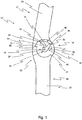
- Figure 1 shows a schematic side view of a joint arrangement 10 according to the invention in a first position.
- the joint arrangement 10 comprises a first joint limb 12 with an elongated first limb section 14 and a first head section 16.
- the joint arrangement 10 comprises a second joint limb 18 with an elongated second limb section 20 and a second head section 22.
- the first and second joint legs 12, 18 overlap.
- the first head section 16 rests against the second head section 22.
- the elongated first leg section 14 and the elongated second leg section 20 are each shown shortened with a curved line. This is intended to make it clear that the length of the elongated first and second leg sections 14, 20 can be selected depending on the use and / or the patient.
- components not shown can be provided in order to integrate the joint arrangement 10 into an orthosis.
- a recess 24 is formed on the first head section 16. Furthermore, a guide body 26 is formed on the second head section 22. The guide body 26 is arranged in the recess 24. Furthermore, the guide body 26 is arranged movably in the recess 24 or the recess 24 is arranged movably around the guide body 26. Because the first head section 16 rests against the second head section 22 and both head sections 16, 22 are designed with essentially flat side surfaces, the first joint leg 12 and the second joint leg 18 can be pivoted relative to one another in a pivot plane. The first joint limb 12 is thus connected in an articulated manner to the second joint limb 18.
- Whether the guide body 26 moves in the recess 24 or whether the recess 24 moves around the guide body 26 depends on which of the joint legs 12, 18 is fixed or pivoted. In principle, it is also possible to pivot both joint legs 12, 18. If the first joint leg 12 is fixed and the second joint leg 18 is pivoted, the guide body 26 moves in the recess 24. If the second joint leg 18 is fixed and the first joint leg 12 is pivoted, the recess moves 24 around the guide body 26. For the sake of simplicity, reference is made to a relative movement between the guide body 26 and the recess 24. This should include both movements.
- the guide body 26 is fastened to the second head section 22 by means of a connecting means 28.
- the guide body 26 comprises an outer contour, the outer contour being teardrop-shaped and curved.
- the guide body 26 thus comprises an inside 30 and an outside 32.
- the inside 30 is arranged on the inside with respect to the curved shape of the guide body 26.
- the outer side 32 is arranged on the outside in relation to the curved shape of the guide body 26.
- the guide body comprises a thickened head region 34 and a tapering extension 36.
- the thickened head region 34 is round and at least partially has a circular shape.
- the extension 36 comprises an extension end 38, the extension end 38 being round.
- the recess 24 comprises an inner contour, the inner contour being heart-shaped.
- the recess 24 comprises a first chamber 40 and a second chamber 42.
- the first chamber 40 is arranged below the second chamber 42.
- the first chamber 40 may be positioned distally and the second chamber 42 may be positioned proximally.
- a projection 44 is formed between the first chamber 40 and the second chamber 42.
- the protrusion 44 is formed into a round shape.
- the first chamber 40 has a contour which is designed such that it can accommodate the thickened head region 34 of the guide body 26. In the present case, the first chamber 40 is round and at least partially has a circular shape.
- the first chamber 40 further comprises a lateral first chamber section 46.
- the second chamber 42 comprises a lateral second chamber section 48.
- the lateral first chamber section 46 and the lateral second chamber section 48 form the sides of the heart shape.
- a heart-shaped base 50 is formed on an underside of the heart shape and between the lateral first chamber section 46 and the lateral second chamber section 48.
- the heart-shaped bottom 50 is round. Furthermore, the heart-shaped bottom 50 connects the lateral first chamber section 46 and the lateral second chamber section 48.
- the heart-shaped bottom 50 is designed in such a way that it can at least partially enclose the extension end 38 of the guide body 26.
- the guide body 26 is arranged in the recess 24 in such a way that it is arranged in the first chamber 40.
- the thickened head region 34 is partially enclosed in the circular shape of the first chamber 40 or enclosed by this.
- the outer side 32 of the guide body 26 lies flat against the lateral first chamber section 48.
- the shape of the outer side 32 corresponds to the shape of the lateral first chamber section 48.
- the extension end 38 of the guide body 26 is arranged in the heart-shaped base 50. Only the inside 30 of the guide body 26 does not make contact or almost does not make contact with the recess 24, and in particular only at one contact point. It can be seen that the shapes of the guide body 26 and recess 24 are matched to one another.
- the guide body 26 is freely enclosed in the recess 24 in such a way that a precisely defined, positively guided relative movement between the guide body 26 and the recess 24 is made possible.
- a first stop element 52 and a second stop element 54 are also formed on the first joint leg 12. More precisely, the first stop element 52 and the second stop element 54 are arranged in the region of the first head section 16. The first stop element 52 is formed close to the projection 44. The second stop element 54 is arranged close to the lateral first chamber section 46.
- a third stop element 56 is formed on the second joint leg 18.
- the third stop element 56 is arranged in the area of the second head section 22.
- the third stop element 56 is also arranged near the thickened head region 34 of the guide body 26.
- the stop elements 52, 54, 56 are designed as steps with a straight surface.
- the first stop element 52 and the third stop element 56 lie flat against one another in the illustration shown.
- the first joint limb 12 and the second joint limb 18 are shown as transparent in the illustration shown, so that the shape of the first head section 16 can be seen even if the first head section 16 is partially overlapped by the second head section 22.
- the first joint leg 12 is oriented differently in relation to the second joint leg 18.
- the first joint leg 12 is pivoted relative to the second joint leg 18 by an angle of approximately 10 °.
- Providing a certain angle can be advantageous in order to reproduce a naturally extended position of an extremity joint. Furthermore, this can be done for an integration of the joint arrangement in an orthosis can be advantageous.
- the angle can also be 0 °.
- Figure 2a shows a schematic side view of the first joint leg 12 according to the invention.
- the recess 24 is formed on the first head section 16.
- the recess 24 comprises the first chamber 40 and the second chamber 42.
- the projection 44 is formed between the first chamber 40 and the second chamber 42.
- the first chamber 40 comprises the lateral first chamber section 46
- the second chamber 42 comprises the lateral second chamber section 48.
- the first chamber 40 comprises a round first chamber head 47.
- the second chamber 42 comprises a round second chamber head 49.
- the second chamber head 49 is smaller than the first chamber head 47.
- the second chamber head 49 is designed to be smaller than the first chamber head 47 in order to better enclose the extension 36 and the extension end 38. In this way a defined bent position can be achieved.
- the first stop element 52 and the second stop element 54 are formed in the area of the first head section 16.
- the first head section 16 is configured to be circular between the first stop element 52 and the second stop element 54.
- the elongated first leg section 14 comprises two parallel sides 58, 59. Furthermore, the elongated first leg section 14 is arranged offset with respect to the first head section 16. More precisely, a centrally arranged longitudinal axis of the elongated first leg section 14 is arranged offset with respect to a center of the first head section 16.
- Figure 2b shows a schematic side view of the second joint leg 18 according to the invention.
- the guide body 26 is formed on the second head section 22.
- the guide body 26 comprises the inside 30 and the outside 32.
- the guide body comprises the thickened head region 34 and the tapering extension 36.
- the extension end 38 is formed on the extension 36.
- the guide body 26 is fixed to the second head section 22 by means of the connecting means 28.
- the third stop element 56 is formed in the area of the second head section 22.
- the second head portion 22 is apart from the third stop element 56 essentially round and partially circular.
- the elongated second leg section 20 is arranged essentially centrally opposite the second head section 22. Furthermore, the elongated second leg section comprises mutually parallel sides 60, 61.
- Both joint legs 12, 18 are shown in plan view. It should therefore be noted that the joint legs 12, 18 each have a constant thickness.
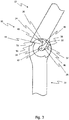
- Figure 3 shows a schematic side view of the joint arrangement 10 according to the invention in a second position.
- the first joint leg 12 is pivoted relative to the second joint leg 18. More precisely, the first joint leg 12 is shown pivoted by an angle of approximately 30 ° with respect to the second joint leg 18.
- the second joint leg 18 is fixed during the pivoting so that its position has not changed.
- the first stop element 52 is now spaced apart from the third stop element 56.
- the outer side 32 of the guide body 26 is no longer at least completely in contact with the lateral first chamber section 46. Rather, the outer side 32 forms an angle with the lateral first chamber section 46.
- the extension end 38 no longer makes contact with the heart-shaped base 50. Rather, the extension end 38 contacts the lateral second chamber section 48 in a central area. In other words, the extension end 38 has moved from the heart-shaped base 50 along the lateral second chamber section 48. The extension end 38 has completed a translational movement relative to the lateral second chamber section 48. In addition, the extension end 38 has approached the second chamber head 49.
- the projection 44 is arranged close to the inner side 30 of the guide body 26 and that it is just not in contact with it.
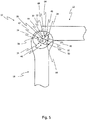
- Figure 4 shows a schematic side view of the joint arrangement 10 according to the invention in a third position. Opposite to Figure 3 it can be seen that the first joint leg 12 is pivoted further relative to the second joint leg 18. More precisely, the first joint leg 12 is shown pivoted by an angle of approximately 64 ° with respect to the second joint leg 18. As before, the second joint leg 18 is fixed during the pivoting so that its position has not changed. The first stop element 52 is even further away from the third stop element 56.
- the outer side 32 of the guide body 26 is further away from the lateral first chamber section 46. Opposite Figure 3 the angle that the outer side 32 forms with the lateral first chamber section 46 has increased.
- extension end 38 contacts the lateral second chamber section 48.
- the extension end 38 has moved along the lateral second chamber section 48.
- the extension end 38 has completed a translational movement relative to the lateral second chamber section 48.
- the extension end 38 has moved closer to the second chamber head 49.
- the projection 44 makes contact with the inside 30 of the guide body 26. More precisely, the projection 44 contacts the inside 30 of the guide body 26 at a first contact point 62. At the first contact point 62, a predetermined section of the inner contour 64 of the recess 24 rolls off a predetermined section of the outer contour 66 of the guide body 26. The predetermined section of the inner contour 64 of the recess 24 executes a rolling movement on the predetermined section of the outer contour 66 of the guide body 26.
- the predetermined section of the inner contour 64 and the predetermined section of the outer contour 66 are modeled on a pole path of the human knee joint. More precisely, the predetermined section of the inner contour 64 is formed on the projection 44. Furthermore, the predetermined section of the inner contour 64 describes a gang pole path of the human knee joint. The predetermined section of the outer contour 66 is formed on the inner side 30 of the guide body 26. Furthermore, the predetermined section of the inner contour 66 describes a latching pole path of the human knee joint.
- Figure 5 shows a schematic side view of the joint arrangement 10 according to the invention in a fourth position.
- the first joint leg 12 is arranged essentially perpendicularly with respect to the second joint leg 18.
- the first joint leg 12 is pivoted further relative to the second joint leg 18.
- the second joint leg 18 is fixed during the gift so that its position has not changed.
- the first stop element 52 is even further away from the third stop element 56.
- the first chamber head 47 is spaced apart from the thickened head region 34 of the guide body 26 Figure 4 the first chamber head 47 is further spaced from the thickened head region 34.
- the thickened head region 34 of the guide body 26 contacts the lateral first chamber section 46.
- the thickened head region 34 has moved along the lateral first chamber section 46 in the direction of the heart-shaped base 50.
- the outer side 32 of the guide body 26 is in turn further away from the lateral first chamber section 46. Opposite Figure 4 the angle that the outer side 32 forms with the lateral first chamber section 46 has increased. Rather, the outer side 32 has approached the lateral second chamber section 48.
- extension end 38 contacts the lateral second chamber section 48.
- the extension end 38 has moved along the lateral second chamber section 48.
- the extension end 38 has completed a translational movement relative to the lateral second chamber section 48.
- the extension end 38 has moved closer to the second chamber head 49.
- the end of the continuation 38 is not yet completely arranged in the second chamber head 49.
- the projection 44 continues to make contact with the inside 30 of the guide body 26. More precisely, the projection 44 makes contact with the inside 30 of the guide body 26 at a second contact point 68. At the second contact point 68, the predefined section of the inner contour 64 rolls off the predefined section of the outer contour 66. The predetermined section of the inner contour 64 of the recess 24 executes a rolling movement on the predetermined section of the outer contour 66 of the guide body 26 opposite Figure 4 it can be seen that the second contact point 68 is arranged further away from the first contact point 62 from the thickened head region 34 and closer to the extension end 38 of the guide body 26.
- Figure 6 shows a schematic side view of the joint arrangement 10 according to the invention in a fifth position.
- the first joint leg 12 is pivoted further relative to the second joint leg 18. More precisely, the first joint leg 12 is shown pivoted by an angle of approximately 110 ° with respect to the second joint leg 18. This angle can be adapted as a function of the outer contour of the guide body 26 and the inner contour of the recess 24.
- the second joint leg 18 is fixed during the pivoting so that its position has not changed.
- the first stop element 52 is even further away from the third stop element 56.
- the first chamber head 47 is spaced apart from the thickened head region 34 of the guide body 26 Figure 5 the first chamber head 47 is further spaced from the thickened head region 34.
- the thickened head region 34 of the guide body 26 contacts the lateral first chamber section 46 and the lateral second chamber section 48.
- the thickened head region 34 has moved along the lateral first chamber section 46.
- the thickened head region 34 has approached the heart-shaped base 50 and is essentially arranged at the heart-shaped base 50.
- the outside 32 of the guide body 26 faces away from the lateral first chamber section 46. Rather, the outside 22 touches the lateral second chamber section 48.
- the extension end 38 contacts the second chamber head 49 and is arranged in it. It can be seen that the extension end 38 has moved along the lateral second chamber section 48. In other words, the extension end 38 has completed a translational movement relative to the lateral second chamber section 48.
- the projection 44 continues to make contact with the inside 30 of the guide body 26. More precisely, the projection 44 makes contact with the inside 30 of the guide body 26 at a third contact point 70.
- the predetermined section of the inner contour 64 rolls onto the predetermined section of the outer contour 66.
- the predetermined section of the inner contour 64 of the recess 24 executes a rolling movement on the predetermined section of the outer contour 66 of the guide body 26 opposite Figure 5
- the third contact point 70 is arranged further away from the first contact point 62 and the second contact point 68 from the thickened head region 34 along the projection 44 and closer to the extension end 38 of the guide body 26.
- the guide body 26 is now essentially arranged in the lateral second chamber section 48. Furthermore, the guide body 26 is arranged in the lateral second chamber section 48 in such a way that no further movement in the direction of the lateral second chamber section 48 or in the direction of the second chamber head 49 is possible. Rather, only one movement can be carried out with which the guide body 26 moves back again in the direction of the lateral first chamber section 46 or in the direction of the first chamber head 47.
- the first leg section 12 is completely pivoted relative to the second leg section 18.
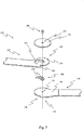
- Figure 7 shows a schematic exploded drawing of a joint arrangement 110 according to the invention.
- the joint arrangement 110 is similar to the previous joint arrangement 10. In the following, therefore, differences will be discussed in particular or features will be explained in more detail, which can now be recognized in an improved manner.
- the joint arrangement 110 comprises a first joint disk 172 with a flexible disk opening 173.
- the first flexible disk 172 can be a sliding disk.
- the first joint disk 172 is circular.
- the first flexible disk 172 has a constant thickness.
- a recess 124 is arranged on a first joint leg 112 in the area of a first head section 116.
- the recess 124 is heart-shaped.
- a first stop element 152 and a second stop element 154 are formed on the first joint leg in the area of the first head section 116.
- the first joint limb 112 has a constant thickness.
- An upper side of the first joint limb 112 is formed parallel to an underside of the first joint limb.
- a guide body 126 is shown, the guide body 126 being teardrop-shaped and including a guide body opening 174.
- An opening 176 is formed on a second joint leg 118 in the area of a second head section 122. Furthermore, a third stop element 156 is formed on the second joint leg 118 in the area of the second head section 122. In addition, a prepared surface 178 is provided on the second joint leg 118 in the region of the second head section 122.
- the second joint leg 118 has a constant thickness. An upper side of the second joint limb 118 is formed parallel to an underside of the first joint limb.
- a bolt 180 is also shown.
- the bolt 180 is designed to connect the first joint washer 172, the first joint leg 112, the guide body 126 and the second joint leg 118 to one another.
- the bolt 180 extends through the joint disk opening 173 and the guide body opening 174 into the opening 176 of the second joint limb 118.
- the first joint disk 172 contacts an upper side of the first joint limb 112 in the area of the first head section 116
- Guide body 126 is arranged in recess 124.
- the guide body 126 is fixedly arranged on the second joint leg 118.
- a connecting means such as an adhesive can additionally or alternatively be provided, which arranges the guide body 126 on the second joint leg 118 in a positionally and rotationally fixed manner.
- the first and second stop elements 152, 154 are designed to be associated with the second joint limb 118 or one associated with the second joint limb 118 Component to work together. In particular, the first and second stop elements 152, 154 are set up to contact a corresponding stop surface assigned to the second joint leg 118. Furthermore, the third stop element 156 is designed to interact with the first joint limb 112 or a component assigned to the first joint limb 112. In particular, the third stop element 156 is set up to contact a corresponding stop surface assigned to the first joint limb 112. In Figure 7 these components or stop surfaces are not shown in more detail. Such components can be further stop elements, plug connections, locking screws, locking clamps, stop disks, stop components and / or other suitable components.
- the first stop element 152 and the third stop element 156 can be designed in such a way that they contact one another in an extended position.
- the components are set up to limit the flexion or extension.
- a therapeutically desired flexion or extension position of the joint arrangement 110 can be set in a targeted manner. If it is not necessary to limit the flexion and / or extension, the stop elements 152, 154, 156 and / or other components (not shown) can be partially or completely omitted.
- the prepared surface 178 is designed in such a way that it has a low surface friction. This is advantageous in order to achieve the lowest possible friction between the first head section 116 and the second head section 122 when the first joint limb 112 is pivoted relative to the second joint limb 118.
- the first flexible disk 172 can also have a surface prepared in this way, at least on its underside.
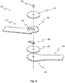
- Figure 8 shows a schematic exploded view of an alternative joint arrangement 210 according to the invention.
- the alternative joint arrangement 210 is designed similarly to the joint arrangement 110 and thus comprises a bolt 280, a first joint washer 272, a first joint leg 212 with a first head section 216 and a recess 224, a guide body 226 and a second joint leg 218 with a second head portion 222.
- the first joint washer 272 can be a sliding washer.
- the alternative joint arrangement 210 additionally comprises a second joint disk 282.
- the second joint disk 282 can be a sliding disk.
- the second joint disk 282 is arranged between the guide body 226 and the second joint leg 218.
- the second articulated disk 282 is designed to work with the guide body 226 and to contact the first joint leg 212 on the one hand and with the second joint leg 218 on the other hand.
- the second flexible disk 218 has reduced friction on an upper side. This is advantageous in order to achieve the lowest possible friction between the first head section 216 and the second head section 222 when the first joint leg 212 is pivoted relative to the second joint leg 218.
- the second joint disk 282 is connected to the second joint limb 212 in a fixed and in particular rotationally fixed manner.
- the second flexible disk 282 is connected to the guide body 226 in a fixed and in particular non-rotatable manner.
- Figure 9 shows a schematic exploded view of an alternative joint arrangement 310 according to the invention.
- the alternative joint arrangement 310 is designed similar to the joint arrangement 110 and thus comprises a bolt 380, a first joint washer 372, a first joint leg 312 with a first head section 316 and a recess 324, a guide body 326 and a second joint leg 318 with a second head portion 322.
- the first joint washer 372 can be a sliding washer.
- the alternative joint arrangement 310 additionally comprises a stop device 384.
- the stop device 384 comprises a first stop surface 386 and a second stop surface 388.
- the first stop surface 386 is designed to interact with a first stop element 352 of the first joint leg 312.
- the second stop surface 388 is designed to interact with a second stop element 354 of the first joint leg 312.
- the stop device 384 is shaped on its inside in such a way that it makes flat contact with an area on the first head section 316 between the first stop surface 386 and the second stop surface 388.
- the stop device 384 has a constant thickness.
- first stop surface 386 Depending on the position of the first stop surface 386 or the position of the second stop surface 388 on the stop device 384, it is possible to adjust the extent of pivoting between the first joint leg 312 and the second joint leg 318 by contacting the first stop element 352 or the second stop element 354 limit.
- a fully extended position between the first joint leg 312 and the second joint leg 318 can thus be achieved as required be adjusted.
- a completely bent position between the first joint leg 312 and the second joint leg 318 can also be adapted as required.
- the first stop surface 386 contacts the first stop element 352.
- the second stop surface 388 contacts the second stop element 354 Stop device be formed.
- the first joint washer 372 contacts the first joint leg 312 and the guide body 326. Furthermore, the first joint leg 312 and the guide body 326 each contact the second joint leg 318 on the other side.
- the area on the first head section 316 between the first stop surface 386 and the second stop surface 388 at least partially contact the stop device 384 on its inside.
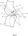
- Figure 10 shows a first schematic representation of a sequence of movements in a knee joint.
- femur 490 and tibia 491 are shown in a first position.
- the tibia 491 is shown in dashed lines in a second position and in dashed lines in a third position.
- a joint gap 492 is formed between femur 490 and tibia 491.
- Femur 490 and tibia 491 are shown in the first position in an extended position or in extension of the knee joint, while the second and third positions of the tibia 491 represent bent positions or positions between extension and flexion of the knee joint.
- first ligament 493 is shown, in particular a first cruciate ligament of the knee joint, which is connected to the tibia 491 at a first connection point 494 and to the femur 490 at a second connection point 495.
- second ligament 496 is shown, in particular a second cruciate ligament of the knee joint, which is connected to the tibia 491 at a third connection point 497 and to the femur 490 at a fourth connection point 498.
- a pole path in the form of a gear pole path 499 is shown as an example.
- the gang pole path 499 describes instantaneous poles of the relative movement between femur 490 and tibia 491, the femur 490 being fixed and the tibia 491 being pivoted relative to the femur 490.
- Figure 11 shows a second schematic representation of a sequence of movements in a knee joint.
- Femur 490 and tibia 491 are shown in the first position.
- the femur 490 is shown in broken lines in a fourth position and in broken lines in a fifth position.
- the joint gap 492 is formed between the femur 490 and the tibia 491.
- first ligament 493 is shown, in particular a first cruciate ligament of the knee joint, which is connected to the tibia 491 at the first connection point 494 and to the femur 490 at the second connection point 495.
- the second ligament 496 is also shown, in particular a second cruciate ligament of the knee joint, which is connected to the tibia 491 at the third connection point 497 and to the femur 490 at the fourth connection point 498.
- a pole track in the form of a latching pole track 500 is shown as an example.
- the latching pole track 500 describes instantaneous poles of the relative movement between femur 490 and tibia 491, the tibia 491 being fixed and the femur 490 being pivoted relative to the tibia 491.
- the shape of the specified section of the inner contour of the recess 24, 124, 224, 324 essentially corresponds to the gear pole track 499. It can also be seen that the specified section of the outer contour of the guide body 26, 126, 226, 326 describes the latching pole track 500. The shape of the specified section of the outer contour of the guide body 26, 126, 226, 326 essentially corresponds to the locking pole path 500.Depending on how the locking pole path 500 or the gang pole path 499 turn out in a patient, the specified section of the outer contour or the specified section can be be adapted to the inner contour and depend on the patient.
Landscapes
- Health & Medical Sciences (AREA)
- Nursing (AREA)
- Orthopedic Medicine & Surgery (AREA)
- Engineering & Computer Science (AREA)
- Biomedical Technology (AREA)
- Heart & Thoracic Surgery (AREA)
- Vascular Medicine (AREA)
- Life Sciences & Earth Sciences (AREA)
- Animal Behavior & Ethology (AREA)
- General Health & Medical Sciences (AREA)
- Public Health (AREA)
- Veterinary Medicine (AREA)
- Orthopedics, Nursing, And Contraception (AREA)
- Prostheses (AREA)
Applications Claiming Priority (1)
| Application Number | Priority Date | Filing Date | Title |
|---|---|---|---|
| DE102020000254.4A DE102020000254A1 (de) | 2020-01-16 | 2020-01-16 | Gelenkanordnung für eine Orthese eines Extremitätengelenks und Orthese mit einer deartigen Gelenkanordnung |
Publications (2)
| Publication Number | Publication Date |
|---|---|
| EP3851081A1 true EP3851081A1 (fr) | 2021-07-21 |
| EP3851081B1 EP3851081B1 (fr) | 2022-04-13 |
Family
ID=74184437
Family Applications (1)
| Application Number | Title | Priority Date | Filing Date |
|---|---|---|---|
| EP21151555.6A Active EP3851081B1 (fr) | 2020-01-16 | 2021-01-14 | Agencement articulaire pour une orthèse d'une articulation d'extrémité et orthèse dotée d'un tel agencement articulaire |
Country Status (2)
| Country | Link |
|---|---|
| EP (1) | EP3851081B1 (fr) |
| DE (1) | DE102020000254A1 (fr) |
Citations (5)
| Publication number | Priority date | Publication date | Assignee | Title |
|---|---|---|---|---|
| US3817244A (en) | 1972-03-03 | 1974-06-18 | Kendall & Co | Knee brace |
| US5244455A (en) | 1991-07-19 | 1993-09-14 | Clinitex Corporation | Knee hinge |
| US20050148916A1 (en) * | 2004-01-07 | 2005-07-07 | Nathanson Jeremy J. | Knee brace hinges with adaptive motion |
| EP1642554A2 (fr) * | 2004-09-27 | 2006-04-05 | Gerhard Lambert | Orthèse du genou |
| AT510403A4 (de) | 2011-05-19 | 2012-04-15 | Kurt Wayd | Gelenk für kniegelenks-orthesen, -prothesen bzw. -stützen |
-
2020
- 2020-01-16 DE DE102020000254.4A patent/DE102020000254A1/de active Pending
-
2021
- 2021-01-14 EP EP21151555.6A patent/EP3851081B1/fr active Active
Patent Citations (6)
| Publication number | Priority date | Publication date | Assignee | Title |
|---|---|---|---|---|
| US3817244A (en) | 1972-03-03 | 1974-06-18 | Kendall & Co | Knee brace |
| US5244455A (en) | 1991-07-19 | 1993-09-14 | Clinitex Corporation | Knee hinge |
| US20050148916A1 (en) * | 2004-01-07 | 2005-07-07 | Nathanson Jeremy J. | Knee brace hinges with adaptive motion |
| EP1642554A2 (fr) * | 2004-09-27 | 2006-04-05 | Gerhard Lambert | Orthèse du genou |
| AT510403A4 (de) | 2011-05-19 | 2012-04-15 | Kurt Wayd | Gelenk für kniegelenks-orthesen, -prothesen bzw. -stützen |
| EP2524672B1 (fr) | 2011-05-19 | 2019-04-10 | Kurt Wayd | Articulation pour soutiens, orthèses ou prothèses du genou |
Also Published As
| Publication number | Publication date |
|---|---|
| EP3851081B1 (fr) | 2022-04-13 |
| DE102020000254A1 (de) | 2021-07-22 |
Similar Documents
| Publication | Publication Date | Title |
|---|---|---|
| DE68928511T2 (de) | Knieorthese mit gesteuerter Mehrachsenbewegung | |
| EP0991381B1 (fr) | Dispositif pour stabiliser une articulation | |
| EP1568337B1 (fr) | Orthèse pour la correction de la position d'une articulation anatomique | |
| EP0880346B1 (fr) | Orthese du genou | |
| DE60310199T2 (de) | Gelenkorthese mit teleskopisch bewegbarem kondylarpolster | |
| DE102017223757B4 (de) | Hartrahmen mit verschwenkbarer Brücke | |
| DE2528583A1 (de) | Geraet zur chirurgischen behandlung von knochen und gelenken | |
| EP0672398A1 (fr) | Liaison pivotante entre des parties d'un dispositif orthopédique | |
| EP2524672B1 (fr) | Articulation pour soutiens, orthèses ou prothèses du genou | |
| AT517182B1 (de) | Führungsgelenk für eine Gelenksorthese | |
| EP3037075A2 (fr) | Orthèse comprenant un dispositif de réglage d'inclinaison | |
| EP1755505B1 (fr) | Orthese de poignet | |
| EP3681445A1 (fr) | Dispositif d'articulation | |
| EP0705582B1 (fr) | Orthèse de l'articulation du genou | |
| DE202018106495U1 (de) | Orthese | |
| EP3448329A1 (fr) | Articulation orthétique, système modulaire pour former une articulation orthétique et utilisation de cette dernière | |
| EP4119108A1 (fr) | Ensemble articulation pour une orthèse d'une articulation des extrémités, kit permettant de régler l'ensemble d'articulation et orthèse dotée d'un tel ensemble d'articulation | |
| EP3851081B1 (fr) | Agencement articulaire pour une orthèse d'une articulation d'extrémité et orthèse dotée d'un tel agencement articulaire | |
| DE102008012996A1 (de) | Orthese | |
| EP4376781A1 (fr) | Orthèse | |
| DE102021002999A1 (de) | Orthopädische Einrichtung zur Erzeugung von bewegungswinkelabhängigen Kräften | |
| DE102016010241B4 (de) | Polyzentrisches Dreh-Gleitgelenk und Knieorthese hiermit | |
| DE102015008031B4 (de) | Knieorthese zum Aufbringen einer nach vorn oder hinten gerichteten Translationskraft | |
| DE102022213570A1 (de) | Reversibel schließbare Extremitätenorthese oder -bandage oder Sporthilfsmittel | |
| DE102021118057A1 (de) | Gelenk für eine Orthese und eine Knieorthese |
Legal Events
| Date | Code | Title | Description |
|---|---|---|---|
| PUAI | Public reference made under article 153(3) epc to a published international application that has entered the european phase |
Free format text: ORIGINAL CODE: 0009012 |
|
| STAA | Information on the status of an ep patent application or granted ep patent |
Free format text: STATUS: THE APPLICATION HAS BEEN PUBLISHED |
|
| AK | Designated contracting states |
Kind code of ref document: A1 Designated state(s): AL AT BE BG CH CY CZ DE DK EE ES FI FR GB GR HR HU IE IS IT LI LT LU LV MC MK MT NL NO PL PT RO RS SE SI SK SM TR |
|
| STAA | Information on the status of an ep patent application or granted ep patent |
Free format text: STATUS: REQUEST FOR EXAMINATION WAS MADE |
|
| 17P | Request for examination filed |
Effective date: 20210805 |
|
| RBV | Designated contracting states (corrected) |
Designated state(s): AL AT BE BG CH CY CZ DE DK EE ES FI FR GB GR HR HU IE IS IT LI LT LU LV MC MK MT NL NO PL PT RO RS SE SI SK SM TR |
|
| RIC1 | Information provided on ipc code assigned before grant |
Ipc: A61F 5/01 20060101AFI20211123BHEP |
|
| GRAP | Despatch of communication of intention to grant a patent |
Free format text: ORIGINAL CODE: EPIDOSNIGR1 |
|
| STAA | Information on the status of an ep patent application or granted ep patent |
Free format text: STATUS: GRANT OF PATENT IS INTENDED |
|
| INTG | Intention to grant announced |
Effective date: 20220107 |
|
| GRAS | Grant fee paid |
Free format text: ORIGINAL CODE: EPIDOSNIGR3 |
|
| GRAA | (expected) grant |
Free format text: ORIGINAL CODE: 0009210 |
|
| STAA | Information on the status of an ep patent application or granted ep patent |
Free format text: STATUS: THE PATENT HAS BEEN GRANTED |
|
| AK | Designated contracting states |
Kind code of ref document: B1 Designated state(s): AL AT BE BG CH CY CZ DE DK EE ES FI FR GB GR HR HU IE IS IT LI LT LU LV MC MK MT NL NO PL PT RO RS SE SI SK SM TR |
|
| REG | Reference to a national code |
Ref country code: GB Ref legal event code: FG4D Free format text: NOT ENGLISH |
|
| REG | Reference to a national code |
Ref country code: CH Ref legal event code: EP |
|
| REG | Reference to a national code |
Ref country code: DE Ref legal event code: R096 Ref document number: 502021000018 Country of ref document: DE |
|
| REG | Reference to a national code |
Ref country code: IE Ref legal event code: FG4D Free format text: LANGUAGE OF EP DOCUMENT: GERMAN |
|
| REG | Reference to a national code |
Ref country code: AT Ref legal event code: REF Ref document number: 1482827 Country of ref document: AT Kind code of ref document: T Effective date: 20220515 |
|
| REG | Reference to a national code |
Ref country code: LT Ref legal event code: MG9D |
|
| REG | Reference to a national code |
Ref country code: NL Ref legal event code: MP Effective date: 20220413 |
|
| PG25 | Lapsed in a contracting state [announced via postgrant information from national office to epo] |
Ref country code: NL Free format text: LAPSE BECAUSE OF FAILURE TO SUBMIT A TRANSLATION OF THE DESCRIPTION OR TO PAY THE FEE WITHIN THE PRESCRIBED TIME-LIMIT Effective date: 20220413 |
|
| PG25 | Lapsed in a contracting state [announced via postgrant information from national office to epo] |
Ref country code: SE Free format text: LAPSE BECAUSE OF FAILURE TO SUBMIT A TRANSLATION OF THE DESCRIPTION OR TO PAY THE FEE WITHIN THE PRESCRIBED TIME-LIMIT Effective date: 20220413 Ref country code: PT Free format text: LAPSE BECAUSE OF FAILURE TO SUBMIT A TRANSLATION OF THE DESCRIPTION OR TO PAY THE FEE WITHIN THE PRESCRIBED TIME-LIMIT Effective date: 20220816 Ref country code: NO Free format text: LAPSE BECAUSE OF FAILURE TO SUBMIT A TRANSLATION OF THE DESCRIPTION OR TO PAY THE FEE WITHIN THE PRESCRIBED TIME-LIMIT Effective date: 20220713 Ref country code: LT Free format text: LAPSE BECAUSE OF FAILURE TO SUBMIT A TRANSLATION OF THE DESCRIPTION OR TO PAY THE FEE WITHIN THE PRESCRIBED TIME-LIMIT Effective date: 20220413 Ref country code: HR Free format text: LAPSE BECAUSE OF FAILURE TO SUBMIT A TRANSLATION OF THE DESCRIPTION OR TO PAY THE FEE WITHIN THE PRESCRIBED TIME-LIMIT Effective date: 20220413 Ref country code: GR Free format text: LAPSE BECAUSE OF FAILURE TO SUBMIT A TRANSLATION OF THE DESCRIPTION OR TO PAY THE FEE WITHIN THE PRESCRIBED TIME-LIMIT Effective date: 20220714 Ref country code: FI Free format text: LAPSE BECAUSE OF FAILURE TO SUBMIT A TRANSLATION OF THE DESCRIPTION OR TO PAY THE FEE WITHIN THE PRESCRIBED TIME-LIMIT Effective date: 20220413 Ref country code: ES Free format text: LAPSE BECAUSE OF FAILURE TO SUBMIT A TRANSLATION OF THE DESCRIPTION OR TO PAY THE FEE WITHIN THE PRESCRIBED TIME-LIMIT Effective date: 20220413 Ref country code: BG Free format text: LAPSE BECAUSE OF FAILURE TO SUBMIT A TRANSLATION OF THE DESCRIPTION OR TO PAY THE FEE WITHIN THE PRESCRIBED TIME-LIMIT Effective date: 20220713 |
|
| PG25 | Lapsed in a contracting state [announced via postgrant information from national office to epo] |
Ref country code: RS Free format text: LAPSE BECAUSE OF FAILURE TO SUBMIT A TRANSLATION OF THE DESCRIPTION OR TO PAY THE FEE WITHIN THE PRESCRIBED TIME-LIMIT Effective date: 20220413 Ref country code: PL Free format text: LAPSE BECAUSE OF FAILURE TO SUBMIT A TRANSLATION OF THE DESCRIPTION OR TO PAY THE FEE WITHIN THE PRESCRIBED TIME-LIMIT Effective date: 20220413 Ref country code: LV Free format text: LAPSE BECAUSE OF FAILURE TO SUBMIT A TRANSLATION OF THE DESCRIPTION OR TO PAY THE FEE WITHIN THE PRESCRIBED TIME-LIMIT Effective date: 20220413 Ref country code: IS Free format text: LAPSE BECAUSE OF FAILURE TO SUBMIT A TRANSLATION OF THE DESCRIPTION OR TO PAY THE FEE WITHIN THE PRESCRIBED TIME-LIMIT Effective date: 20220813 |
|
| REG | Reference to a national code |
Ref country code: DE Ref legal event code: R097 Ref document number: 502021000018 Country of ref document: DE |
|
| PG25 | Lapsed in a contracting state [announced via postgrant information from national office to epo] |
Ref country code: SM Free format text: LAPSE BECAUSE OF FAILURE TO SUBMIT A TRANSLATION OF THE DESCRIPTION OR TO PAY THE FEE WITHIN THE PRESCRIBED TIME-LIMIT Effective date: 20220413 Ref country code: SK Free format text: LAPSE BECAUSE OF FAILURE TO SUBMIT A TRANSLATION OF THE DESCRIPTION OR TO PAY THE FEE WITHIN THE PRESCRIBED TIME-LIMIT Effective date: 20220413 Ref country code: RO Free format text: LAPSE BECAUSE OF FAILURE TO SUBMIT A TRANSLATION OF THE DESCRIPTION OR TO PAY THE FEE WITHIN THE PRESCRIBED TIME-LIMIT Effective date: 20220413 Ref country code: EE Free format text: LAPSE BECAUSE OF FAILURE TO SUBMIT A TRANSLATION OF THE DESCRIPTION OR TO PAY THE FEE WITHIN THE PRESCRIBED TIME-LIMIT Effective date: 20220413 Ref country code: DK Free format text: LAPSE BECAUSE OF FAILURE TO SUBMIT A TRANSLATION OF THE DESCRIPTION OR TO PAY THE FEE WITHIN THE PRESCRIBED TIME-LIMIT Effective date: 20220413 Ref country code: CZ Free format text: LAPSE BECAUSE OF FAILURE TO SUBMIT A TRANSLATION OF THE DESCRIPTION OR TO PAY THE FEE WITHIN THE PRESCRIBED TIME-LIMIT Effective date: 20220413 |
|
| PLBE | No opposition filed within time limit |
Free format text: ORIGINAL CODE: 0009261 |
|
| STAA | Information on the status of an ep patent application or granted ep patent |
Free format text: STATUS: NO OPPOSITION FILED WITHIN TIME LIMIT |
|
| 26N | No opposition filed |
Effective date: 20230116 |
|
| PG25 | Lapsed in a contracting state [announced via postgrant information from national office to epo] |
Ref country code: AL Free format text: LAPSE BECAUSE OF FAILURE TO SUBMIT A TRANSLATION OF THE DESCRIPTION OR TO PAY THE FEE WITHIN THE PRESCRIBED TIME-LIMIT Effective date: 20220413 |
|
| PG25 | Lapsed in a contracting state [announced via postgrant information from national office to epo] |
Ref country code: SI Free format text: LAPSE BECAUSE OF FAILURE TO SUBMIT A TRANSLATION OF THE DESCRIPTION OR TO PAY THE FEE WITHIN THE PRESCRIBED TIME-LIMIT Effective date: 20220413 |
|
| P01 | Opt-out of the competence of the unified patent court (upc) registered |
Effective date: 20230404 |
|
| PG25 | Lapsed in a contracting state [announced via postgrant information from national office to epo] |
Ref country code: LU Free format text: LAPSE BECAUSE OF NON-PAYMENT OF DUE FEES Effective date: 20230114 |
|
| REG | Reference to a national code |
Ref country code: BE Ref legal event code: MM Effective date: 20230131 |
|
| PG25 | Lapsed in a contracting state [announced via postgrant information from national office to epo] |
Ref country code: BE Free format text: LAPSE BECAUSE OF NON-PAYMENT OF DUE FEES Effective date: 20230131 |
|
| PG25 | Lapsed in a contracting state [announced via postgrant information from national office to epo] |
Ref country code: IT Free format text: LAPSE BECAUSE OF FAILURE TO SUBMIT A TRANSLATION OF THE DESCRIPTION OR TO PAY THE FEE WITHIN THE PRESCRIBED TIME-LIMIT Effective date: 20220413 Ref country code: IE Free format text: LAPSE BECAUSE OF NON-PAYMENT OF DUE FEES Effective date: 20230114 |
|
| PG25 | Lapsed in a contracting state [announced via postgrant information from national office to epo] |
Ref country code: MC Free format text: LAPSE BECAUSE OF FAILURE TO SUBMIT A TRANSLATION OF THE DESCRIPTION OR TO PAY THE FEE WITHIN THE PRESCRIBED TIME-LIMIT Effective date: 20220413 |
|
| PG25 | Lapsed in a contracting state [announced via postgrant information from national office to epo] |
Ref country code: MC Free format text: LAPSE BECAUSE OF FAILURE TO SUBMIT A TRANSLATION OF THE DESCRIPTION OR TO PAY THE FEE WITHIN THE PRESCRIBED TIME-LIMIT Effective date: 20220413 |
|
| PG25 | Lapsed in a contracting state [announced via postgrant information from national office to epo] |
Ref country code: BG Free format text: LAPSE BECAUSE OF FAILURE TO SUBMIT A TRANSLATION OF THE DESCRIPTION OR TO PAY THE FEE WITHIN THE PRESCRIBED TIME-LIMIT Effective date: 20220413 |
|
| PG25 | Lapsed in a contracting state [announced via postgrant information from national office to epo] |
Ref country code: BG Free format text: LAPSE BECAUSE OF FAILURE TO SUBMIT A TRANSLATION OF THE DESCRIPTION OR TO PAY THE FEE WITHIN THE PRESCRIBED TIME-LIMIT Effective date: 20220413 |
|
| PGFP | Annual fee paid to national office [announced via postgrant information from national office to epo] |
Ref country code: AT Payment date: 20250417 Year of fee payment: 5 |
|
| PG25 | Lapsed in a contracting state [announced via postgrant information from national office to epo] |
Ref country code: CY Free format text: LAPSE BECAUSE OF FAILURE TO SUBMIT A TRANSLATION OF THE DESCRIPTION OR TO PAY THE FEE WITHIN THE PRESCRIBED TIME-LIMIT; INVALID AB INITIO Effective date: 20210114 |
|
| PG25 | Lapsed in a contracting state [announced via postgrant information from national office to epo] |
Ref country code: HU Free format text: LAPSE BECAUSE OF FAILURE TO SUBMIT A TRANSLATION OF THE DESCRIPTION OR TO PAY THE FEE WITHIN THE PRESCRIBED TIME-LIMIT; INVALID AB INITIO Effective date: 20210114 |
|
| PG25 | Lapsed in a contracting state [announced via postgrant information from national office to epo] |
Ref country code: TR Free format text: LAPSE BECAUSE OF FAILURE TO SUBMIT A TRANSLATION OF THE DESCRIPTION OR TO PAY THE FEE WITHIN THE PRESCRIBED TIME-LIMIT Effective date: 20220413 |
|
| REG | Reference to a national code |
Ref country code: CH Ref legal event code: U11 Free format text: ST27 STATUS EVENT CODE: U-0-0-U10-U11 (AS PROVIDED BY THE NATIONAL OFFICE) Effective date: 20260201 |
|
| PGFP | Annual fee paid to national office [announced via postgrant information from national office to epo] |
Ref country code: GB Payment date: 20260122 Year of fee payment: 6 |
|
| PGFP | Annual fee paid to national office [announced via postgrant information from national office to epo] |
Ref country code: DE Payment date: 20260120 Year of fee payment: 6 |
|
| PGFP | Annual fee paid to national office [announced via postgrant information from national office to epo] |
Ref country code: FR Payment date: 20260121 Year of fee payment: 6 |
|
| PGFP | Annual fee paid to national office [announced via postgrant information from national office to epo] |
Ref country code: CH Payment date: 20260201 Year of fee payment: 6 |