EP3851182A1 - Élément de filtre - Google Patents
Élément de filtre Download PDFInfo
- Publication number
- EP3851182A1 EP3851182A1 EP21151250.4A EP21151250A EP3851182A1 EP 3851182 A1 EP3851182 A1 EP 3851182A1 EP 21151250 A EP21151250 A EP 21151250A EP 3851182 A1 EP3851182 A1 EP 3851182A1
- Authority
- EP
- European Patent Office
- Prior art keywords
- membrane
- filter element
- electroactive polymer
- liquid
- vibration
- Prior art date
- Legal status (The legal status is an assumption and is not a legal conclusion. Google has not performed a legal analysis and makes no representation as to the accuracy of the status listed.)
- Withdrawn
Links
- 239000012528 membrane Substances 0.000 claims abstract description 82
- 229920001746 electroactive polymer Polymers 0.000 claims abstract description 60
- 239000000126 substance Substances 0.000 claims abstract description 9
- 239000012466 permeate Substances 0.000 claims description 23
- 239000007788 liquid Substances 0.000 claims description 21
- 125000006850 spacer group Chemical group 0.000 claims description 21
- 238000000034 method Methods 0.000 claims description 15
- 238000009413 insulation Methods 0.000 claims description 6
- 230000035699 permeability Effects 0.000 claims description 5
- 229910010293 ceramic material Inorganic materials 0.000 claims description 3
- 229920000642 polymer Polymers 0.000 claims description 3
- 239000011368 organic material Substances 0.000 claims description 2
- 238000004140 cleaning Methods 0.000 description 16
- 239000002245 particle Substances 0.000 description 13
- XLYOFNOQVPJJNP-UHFFFAOYSA-N water Substances O XLYOFNOQVPJJNP-UHFFFAOYSA-N 0.000 description 8
- 230000008569 process Effects 0.000 description 5
- 238000010276 construction Methods 0.000 description 4
- 238000000926 separation method Methods 0.000 description 3
- 238000011109 contamination Methods 0.000 description 2
- 230000001419 dependent effect Effects 0.000 description 2
- 238000011017 operating method Methods 0.000 description 2
- 244000089486 Phragmites australis subsp australis Species 0.000 description 1
- 238000009825 accumulation Methods 0.000 description 1
- 230000000712 assembly Effects 0.000 description 1
- 238000000429 assembly Methods 0.000 description 1
- 230000008859 change Effects 0.000 description 1
- 239000013078 crystal Substances 0.000 description 1
- 238000011161 development Methods 0.000 description 1
- 230000018109 developmental process Effects 0.000 description 1
- 230000000694 effects Effects 0.000 description 1
- 230000006698 induction Effects 0.000 description 1
- 239000004615 ingredient Substances 0.000 description 1
- 238000009434 installation Methods 0.000 description 1
- 239000000463 material Substances 0.000 description 1
- 230000007246 mechanism Effects 0.000 description 1
- 238000000638 solvent extraction Methods 0.000 description 1
- 230000001960 triggered effect Effects 0.000 description 1
Images


Classifications
-
- B—PERFORMING OPERATIONS; TRANSPORTING
- B01—PHYSICAL OR CHEMICAL PROCESSES OR APPARATUS IN GENERAL
- B01D—SEPARATION
- B01D65/00—Accessories or auxiliary operations, in general, for separation processes or apparatus using semi-permeable membranes
- B01D65/08—Prevention of membrane fouling or of concentration polarisation
-
- B—PERFORMING OPERATIONS; TRANSPORTING
- B01—PHYSICAL OR CHEMICAL PROCESSES OR APPARATUS IN GENERAL
- B01D—SEPARATION
- B01D65/00—Accessories or auxiliary operations, in general, for separation processes or apparatus using semi-permeable membranes
- B01D65/02—Membrane cleaning or sterilisation ; Membrane regeneration
-
- B—PERFORMING OPERATIONS; TRANSPORTING
- B01—PHYSICAL OR CHEMICAL PROCESSES OR APPARATUS IN GENERAL
- B01D—SEPARATION
- B01D2315/00—Details relating to the membrane module operation
- B01D2315/04—Reciprocation, oscillation or vibration
-
- B—PERFORMING OPERATIONS; TRANSPORTING
- B01—PHYSICAL OR CHEMICAL PROCESSES OR APPARATUS IN GENERAL
- B01D—SEPARATION
- B01D2321/00—Details relating to membrane cleaning, regeneration, sterilization or to the prevention of fouling
- B01D2321/20—By influencing the flow
- B01D2321/2033—By influencing the flow dynamically
- B01D2321/2058—By influencing the flow dynamically by vibration of the membrane, e.g. with an actuator
Definitions
- the invention relates to a filter element for separating substances and to an operating method for such a filter element.
- the prior art discloses membranes for cleaning processes which can be used both in the medium of air and in the medium of water.
- these membranes are used as filters for cleaning air flows with the aim of separating particles.
- water flows are separated from particulate, colloidal and dissolved substances.
- a physical separation of substances thus purifies the medium air or the medium water.
- the achieved separation of substances can also generate concentrated media flows by leaving the separated particles or ingredients in a smaller media volume.
- a filter element for separating substances comprises a membrane and a vibration generator.
- the vibration generator has electroactive polymer. It can be provided that the vibration generator is arranged in the area of the membrane. This makes it possible to introduce a vibration into the filter element close to the membrane and thus to generate a cleaning effect on the membrane that requires significantly less energy.
- Electroactive polymers are suitable for this because electroactive polymers are suitable on the one hand to generate vibrations and on the other hand their application is much easier, since electroactive polymers are much more flexible in shape than the piezo crystals or vibrating motors used in conventional processes.
- One goal is to enable needs-based cleaning in which the vibration can be adapted to the degree of contamination of the membrane.
- the filter element has a permeate spacer which adjoins the membrane.
- the permeate spacer can in particular serve to move the permeate, ie the liquid that has a lower concentration of the particles to be filtered out than the starting liquid, away from the membrane when the filter element is used in a liquid medium such as water.
- the permeate spacer can be permeable to the liquid.
- the permeate spacer is arranged between the electroactive polymer and the membrane. This enables the permeate to be routed efficiently through the permeate spacer, while at the same time both the permeate spacer and the membrane can simply continue to vibrate via the electroactive polymer.
- the electroactive polymer acts as a permeate spacer. This is particularly the case when the electroactive polymer is permeable to the liquid to be filtered. In particular, an efficient construction of the filter element is made possible.
- the electroactive polymer is embedded in a membrane holder.
- the membrane is held by the membrane holder.
- the membrane holder can, for example, be designed to run around an edge of the membrane.
- the electroactive polymer can be integrated into this membrane holder.
- the electroactive polymer is also arranged circumferentially around the membrane.
- the membrane holder consists entirely of the electroactive polymer.
- a plurality of membranes are embedded in the membrane holder. The multiple membranes embedded in the membrane holder can be arranged parallel to one another.
- the electroactive polymer is stable in a liquid to be filtered, in particular in water.
- the electroactive polymer can be applied directly to the membrane and in particular can also be used as a permeate spacer, since the liquid to be filtered does not attack the electroactive polymer.
- the electroactive polymer is enclosed in a liquid-tight manner with an insulation layer.
- the electroactive polymer cannot serve as a permeate spacer, a corresponding partitioning of the electroactive polymer can be achieved by means of the insulation layer.
- electroactive polymers can also be used which would not be stable in the liquid to be filtered.
- the membrane has an organic material, for example a polymer and / or a ceramic material. This enables a simple and efficient construction of the membrane.
- the invention further comprises a method for operating a filter element according to the invention, in which the electroactive polymer is excited to vibrate. This can in principle take place during a cleaning step, but also during continuous operation of the filter element. If the vibration is generated during a cleaning step, the filtered out particles can be detached from the membrane again during the cleaning process. If the vibration is excited in continuous operation, it can be achieved that the particles do not adhere to the membrane at all.
- an alternating voltage is applied to the electroactive polymer.
- the alternating voltage can have a frequency between 50 and 200 Hertz.
- the alternating voltage can have an effective value between five hundred volts and three kilovolts.
- the said operating parameters of the alternating voltage are suitable for causing the membrane to vibrate which, on the one hand, enables a cleaning process and, on the other hand, largely avoids the accumulation of particles on the membrane in continuous operation.
- the frequency and / or the effective value are changed. For example, more efficient cleaning can be achieved if the amplitude of the vibration, set via the rms value of the alternating voltage, or the frequency of the vibration is changed during the cleaning process and thus different particles can be detached from the membrane.
- a permeability of the membrane is set by means of the electroactive polymer. It can be provided that the permeability is adjusted by means of the generated vibration.
- the permeability of the membrane can be adjusted via the electroactive polymer without the electroactive polymer is excited to vibrate. This can take place, for example, via a voltage-dependent expansion of the electroactive polymer.
- Fig. 1 shows a first exemplary embodiment of a filter element 100.
- the filter element 100 can be used for material separation and comprises a membrane 110 and a vibration generator 120, the vibration generator 120 having an electroactive polymer 121.
- the vibration generator 120 can consist of the electroactive polymer 121.
- the vibration generator 120 has a first side 122 and a second side 123. It can be provided that a first connection 124 is arranged on the first side 122 and a second connection 125 is arranged on the second side 123.
- a voltage can be applied to the electroactive polymer 121 via the first connection 124 and the second connection 125.
- the electroactive polymer 121 is excited to vibrate, it being possible for this to be triggered by the voltage applied to the first connection 124 and the second connection 125.
- an alternating voltage is applied to the electroactive polymer 121 between the first connection 124 and the second connection 125.
- the alternating voltage can have a frequency between 50 and 200 Hertz. Additionally or alternatively, the alternating voltage can have an effective value between five hundred volts and three kilovolts.
- the parameters mentioned for the alternating voltage have been shown to be advantageous with regard to generating vibrations by means of the electroactive polymer 121. In one embodiment it can be provided to vary the alternating voltage, the frequency and / or the effective value of the alternating voltage.
- the electroactive polymer 121 can be stable in a liquid to be filtered. This means in particular that the electroactive polymer 121 is not attacked or decomposed by the liquid to be filtered.
- FIG. 10 shows the filter element 100 of FIG Fig. 1 installed in a pipe 130.
- a gas for example air, or a liquid, for example water
- the filter element 100 can be used, for example, to remove from the gas or the liquid.
- the particles can be filtered out on the filter element 100 or the membrane 110, so that a purified liquid or a purified gas is present behind the filter element 100.
- the particles can be removed again from the membrane 110 by means of the vibration generator 120, for example by generating a vibration by means of the electroactive polymer 121.
- FIG. 3 shows a second exemplary embodiment of a filter element 100 which corresponds to the filter element 100 of FIG Figures 1 and 2 if no differences are described below.
- the filter element 100 can Fig. 3 analogous to the filter element 100 of Fig. 2 be inserted into the tube 130.
- a permeate spacer 140 is arranged between the vibration generator 120 and the membrane 110.
- the permeate spacer 140 can serve to move purified gas or a purified liquid away from the membrane 110.
- the permeate spacer 140 can in particular be used when the filter element 100 is to be suitable for cleaning from a liquid.
- the vibration generator 120 and the permeate spacer 140 form a common layer that contains the electroactive polymer 121. This is possible in particular when the electroactive polymer 121 is stable in a liquid to be filtered. In this case, the electroactive polymer 121 acts Fig. 1 also as a permeate spacer 140.
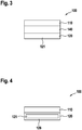
- FIG. 3 shows a third exemplary embodiment of a filter element 100 which corresponds to the filter element 100 of FIG Fig. 1 if no differences are described below.
- the vibration generator 120 has an electroactive polymer 121 which is enclosed with an insulation layer 126.
- the insulation layer 126 can be embodied in a liquid-tight manner.
- the insulation layer 126 serves to isolate the electroactive polymer 121 from a gas to be filtered or a liquid to be filtered. This is particularly helpful if the liquid to be filtered could otherwise lead to a short circuit when a voltage is applied to the electroactive polymer 121.
- the filter element 100 of the Fig. 4 can analogously to the filter element 100 of the Fig. 2 can be inserted into the tube 130.
- Analogous to Fig. 3 can in the filter element 100 of Fig. 4 a permeate spacer 140 can also be arranged between the membrane 110 and the vibration generator 120.
- Fig. 5 shows a fourth exemplary embodiment of a filter element 100.
- the membrane 110 is held in a membrane holder 111.
- the vibration generator 120 in the form of the electroactive polymer 121 is embedded within the membrane holder 111.
- This embodiment enables the efficient construction of the filter element 100, since in this case the membrane 110 is arranged in large parts within the parts of the membrane holder 111 and, if the filter element 100 of the Fig. 5 is built into the pipe 130 of the figure, in the pipe 130 the gas to be filtered or the liquid to be filtered only has to penetrate through the membrane 110.
- the membrane holder 111 can circumferentially around the Membrane 110 be arranged. If this is the case, the electroactive polymer 121 can likewise be arranged circumferentially around the membrane 110.
- Fig. 6 shows a fifth embodiment of a filter element 100, in which the membrane 110 is designed in the form of a pocket membrane.
- the membrane 110 has three pockets 112, the membrane 110 thereby having a zigzag shape.
- a permeate spacer 140 is arranged on one side of the membrane 110, which is used in particular to achieve that different sections of the membrane 110 are arranged at a distance from one another.
- the membrane 110 is in turn arranged in a membrane holder 111 which comprises the vibration generator 120 in the form of the electroactive polymer 121.
- This filter element 100 can in turn also be inserted into the tube 130 of Fig. 2 can be used.
- the vibration generator 120 is installed on the other side of the permeate spacer 140 in a manner analogous to FIG Fig. 3 to be provided and to omit the membrane holder 111.
- the permeate spacer 140 is again arranged between the vibration generator 120 and the membrane 110.
- the filter elements 100 shown can be configured in the form of a pocket membrane.
- the membrane 110 can comprise a polymer and / or a ceramic material.
- the electroactive polymer 121 shown can be constructed as in the publications US 2016/301330 A1 respectively U.S. 9,195,058 disclosed. With regard to the construction and structure of the electroactive polymer, reference is made to the two cited publications and their contents are fully incorporated by reference.
- the exemplary embodiments shown allow the following advantages to be achieved: Due to the direct induction of the vibrations on the membranes 110 by means of the electroactive polymers 121, significantly lower vibration amplitudes are necessary than in the prior art, in which entire filter assemblies or the entire filter component have to be excited to vibrate. Furthermore, electroactive polymers provide robust, scalable and energy-efficient vibration generators. The vibration enables an efficient cleaning mechanism. Provision can also be made to regulate the vibration dynamically and, for example, to operate the vibration in a pulsed manner during operation, to control an amplitude of the vibration via an effective value of an applied alternating voltage, to change a frequency of the alternating voltage and to use different types of control. Provision can also be made to use different vibration options with regard to the currently present particles to be filtered out. It can be provided in particular to use a specially designed vibration program for certain types of contamination or filtered out particles.
Landscapes
- Chemical & Material Sciences (AREA)
- Chemical Kinetics & Catalysis (AREA)
- Separation Using Semi-Permeable Membranes (AREA)
Applications Claiming Priority (1)
| Application Number | Priority Date | Filing Date | Title |
|---|---|---|---|
| DE102020200350.5A DE102020200350A1 (de) | 2020-01-14 | 2020-01-14 | Filterelement |
Publications (1)
| Publication Number | Publication Date |
|---|---|
| EP3851182A1 true EP3851182A1 (fr) | 2021-07-21 |
Family
ID=74175697
Family Applications (1)
| Application Number | Title | Priority Date | Filing Date |
|---|---|---|---|
| EP21151250.4A Withdrawn EP3851182A1 (fr) | 2020-01-14 | 2021-01-13 | Élément de filtre |
Country Status (2)
| Country | Link |
|---|---|
| EP (1) | EP3851182A1 (fr) |
| DE (1) | DE102020200350A1 (fr) |
Cited By (1)
| Publication number | Priority date | Publication date | Assignee | Title |
|---|---|---|---|---|
| CN116297219A (zh) * | 2023-02-28 | 2023-06-23 | 西安交通大学 | 一种可自动除尘的光声光谱式气体传感器 |
Citations (7)
| Publication number | Priority date | Publication date | Assignee | Title |
|---|---|---|---|---|
| US4904394A (en) * | 1985-06-12 | 1990-02-27 | Public Health Laboratory Service Board | Method for selective filtering of a fluid using porous piezoelectric material |
| US20080180500A1 (en) * | 2007-01-30 | 2008-07-31 | Brother Kogyo Kabushiki Kaisha | Filter, liquid jetting apparatus, and liquid transporting apparatus |
| US20140151298A1 (en) * | 2012-12-04 | 2014-06-05 | James Jeffrey Harris | Method and System for Enhanced Osmotic Mass Transfer |
| US9195058B2 (en) | 2011-03-22 | 2015-11-24 | Parker-Hannifin Corporation | Electroactive polymer actuator lenticular system |
| US20160301330A1 (en) | 2013-11-13 | 2016-10-13 | Single Buoy Moorings Inc. | Multi-phase eap system and method for controlling such a system |
| WO2017194999A1 (fr) * | 2016-05-13 | 2017-11-16 | Acondicionamiento Tarrasense | Système de vibration et plaque filtrante pour la filtration de substances |
| US20180296983A1 (en) * | 2015-01-09 | 2018-10-18 | Elwha Llc | Device including multilayer membrane to control fluid drainage and methods of use thereof |
-
2020
- 2020-01-14 DE DE102020200350.5A patent/DE102020200350A1/de active Pending
-
2021
- 2021-01-13 EP EP21151250.4A patent/EP3851182A1/fr not_active Withdrawn
Patent Citations (7)
| Publication number | Priority date | Publication date | Assignee | Title |
|---|---|---|---|---|
| US4904394A (en) * | 1985-06-12 | 1990-02-27 | Public Health Laboratory Service Board | Method for selective filtering of a fluid using porous piezoelectric material |
| US20080180500A1 (en) * | 2007-01-30 | 2008-07-31 | Brother Kogyo Kabushiki Kaisha | Filter, liquid jetting apparatus, and liquid transporting apparatus |
| US9195058B2 (en) | 2011-03-22 | 2015-11-24 | Parker-Hannifin Corporation | Electroactive polymer actuator lenticular system |
| US20140151298A1 (en) * | 2012-12-04 | 2014-06-05 | James Jeffrey Harris | Method and System for Enhanced Osmotic Mass Transfer |
| US20160301330A1 (en) | 2013-11-13 | 2016-10-13 | Single Buoy Moorings Inc. | Multi-phase eap system and method for controlling such a system |
| US20180296983A1 (en) * | 2015-01-09 | 2018-10-18 | Elwha Llc | Device including multilayer membrane to control fluid drainage and methods of use thereof |
| WO2017194999A1 (fr) * | 2016-05-13 | 2017-11-16 | Acondicionamiento Tarrasense | Système de vibration et plaque filtrante pour la filtration de substances |
Cited By (1)
| Publication number | Priority date | Publication date | Assignee | Title |
|---|---|---|---|---|
| CN116297219A (zh) * | 2023-02-28 | 2023-06-23 | 西安交通大学 | 一种可自动除尘的光声光谱式气体传感器 |
Also Published As
| Publication number | Publication date |
|---|---|
| DE102020200350A1 (de) | 2021-07-15 |
Similar Documents
| Publication | Publication Date | Title |
|---|---|---|
| DE69634516T2 (de) | Nicht verschmutzender durchflusskondensator | |
| DE60034247T2 (de) | Elektrisch leitfähige filterpatrone | |
| DE68912169T2 (de) | Verfahren zum Betreiben von Membrantrenneinrichtungen. | |
| EP3562276B1 (fr) | Dispositif de traitement de liquides assisté par plasma | |
| AT513225B1 (de) | Verfahren zur Filtration von Flüssigkeiten | |
| WO2015154999A1 (fr) | Dispositif de séparation d'une émulsion et/ou d'une suspension | |
| DE2231868B2 (de) | Zelle zur Duchführung der umgekehrten Osmose | |
| DE102019203032A1 (de) | Elektrostatische Filtereinheit für Luftreinigungsvorrichtung und Luftreinigungsvorrichtung | |
| DE4308390C2 (de) | Verfahren zum Aufladen, Koagulieren und Ausfiltern von in Fluiden vorkommenden Schwebstoffen, ein in diesem Verfahren verwendetes Filterelement und eine Fluidfiltervorrichtung | |
| DE3916744A1 (de) | Rohrfoermiges filterelement | |
| DE3629102A1 (de) | Fluessigkeitsfiltereinrichtung | |
| EP3851182A1 (fr) | Élément de filtre | |
| WO2004030855A1 (fr) | Dispositif de nettoyage et procede pour nettoyer le gaz de process d'une installation de brasage par fusion | |
| DE202018105060U1 (de) | Luftzuführeinrichtung | |
| EP2739371A2 (fr) | Appareil de filtration de liquides, en particulier d'eaux usées, et procédé pour filtrer des liquides | |
| EP3789350A1 (fr) | Procédé et installation de traitement des eaux | |
| EP1381442B1 (fr) | Dispositif de filtration | |
| EP2041498A1 (fr) | Échangeur d'humidité comprenant un dispositif de nettoyage | |
| DE4143423C2 (de) | Ultrafiltrationsvorrichtung | |
| DE69607305T2 (de) | In-situ-Filterreinigung | |
| EP0885056B1 (fr) | Systeme pour la filtration membranaire a courant transversal | |
| EP0249893A2 (fr) | Dispositif de séparation d'un liquide et/ou un gaz d'un mélange | |
| WO2019081165A1 (fr) | Dispositif de filtre à carburant pour un moteur à combustion interne | |
| DE2216436A1 (de) | Staubfiltervorrichtung | |
| DE19730331C1 (de) | Anlage zur Reinigung von elektrisch nichtleitenden Flüssigkeiten, insbesondere Pflanzenölen |
Legal Events
| Date | Code | Title | Description |
|---|---|---|---|
| PUAI | Public reference made under article 153(3) epc to a published international application that has entered the european phase |
Free format text: ORIGINAL CODE: 0009012 |
|
| STAA | Information on the status of an ep patent application or granted ep patent |
Free format text: STATUS: THE APPLICATION HAS BEEN PUBLISHED |
|
| AK | Designated contracting states |
Kind code of ref document: A1 Designated state(s): AL AT BE BG CH CY CZ DE DK EE ES FI FR GB GR HR HU IE IS IT LI LT LU LV MC MK MT NL NO PL PT RO RS SE SI SK SM TR |
|
| STAA | Information on the status of an ep patent application or granted ep patent |
Free format text: STATUS: REQUEST FOR EXAMINATION WAS MADE |
|
| 17P | Request for examination filed |
Effective date: 20220121 |
|
| RBV | Designated contracting states (corrected) |
Designated state(s): AL AT BE BG CH CY CZ DE DK EE ES FI FR GB GR HR HU IE IS IT LI LT LU LV MC MK MT NL NO PL PT RO RS SE SI SK SM TR |
|
| STAA | Information on the status of an ep patent application or granted ep patent |
Free format text: STATUS: THE APPLICATION IS DEEMED TO BE WITHDRAWN |
|
| 18D | Application deemed to be withdrawn |
Effective date: 20220122 |