EP3851201B1 - Drehbarer sprinkler - Google Patents
Drehbarer sprinkler Download PDFInfo
- Publication number
- EP3851201B1 EP3851201B1 EP20152052.5A EP20152052A EP3851201B1 EP 3851201 B1 EP3851201 B1 EP 3851201B1 EP 20152052 A EP20152052 A EP 20152052A EP 3851201 B1 EP3851201 B1 EP 3851201B1
- Authority
- EP
- European Patent Office
- Prior art keywords
- rotation element
- base
- support
- rotatable sprinkler
- decorative unit
- Prior art date
- Legal status (The legal status is an assumption and is not a legal conclusion. Google has not performed a legal analysis and makes no representation as to the accuracy of the status listed.)
- Active
Links
Images

Classifications
-
- B—PERFORMING OPERATIONS; TRANSPORTING
- B05—SPRAYING OR ATOMISING IN GENERAL; APPLYING FLUENT MATERIALS TO SURFACES, IN GENERAL
- B05B—SPRAYING APPARATUS; ATOMISING APPARATUS; NOZZLES
- B05B3/00—Spraying or sprinkling apparatus with moving outlet elements or moving deflecting elements
- B05B3/02—Spraying or sprinkling apparatus with moving outlet elements or moving deflecting elements with rotating elements
- B05B3/04—Spraying or sprinkling apparatus with moving outlet elements or moving deflecting elements with rotating elements driven by the liquid or other fluent material discharged, e.g. the liquid actuating a motor before passing to the outlet
- B05B3/0417—Spraying or sprinkling apparatus with moving outlet elements or moving deflecting elements with rotating elements driven by the liquid or other fluent material discharged, e.g. the liquid actuating a motor before passing to the outlet comprising a liquid driven rotor, e.g. a turbine
- B05B3/0429—Spraying or sprinkling apparatus with moving outlet elements or moving deflecting elements with rotating elements driven by the liquid or other fluent material discharged, e.g. the liquid actuating a motor before passing to the outlet comprising a liquid driven rotor, e.g. a turbine the rotating outlet elements being directly attached to the rotor or being an integral part thereof
-
- B—PERFORMING OPERATIONS; TRANSPORTING
- B05—SPRAYING OR ATOMISING IN GENERAL; APPLYING FLUENT MATERIALS TO SURFACES, IN GENERAL
- B05B—SPRAYING APPARATUS; ATOMISING APPARATUS; NOZZLES
- B05B1/00—Nozzles, spray heads or other outlets, with or without auxiliary devices such as valves, heating means
- B05B1/14—Nozzles, spray heads or other outlets, with or without auxiliary devices such as valves, heating means with multiple outlet openings; with strainers in or outside the outlet opening
Definitions
- the present invention relates generally to a rotatable spray device, and more particularly to a rotatable sprinkler with a decorative function.
- the rotatable sprinkler used in gardening is driven by a plurality of blades, or by a rotating torque generated through the direction of the fluid in the runner pipe, so that the sprinkler rotates to spray the water in all directions to achieve the full spraying.
- the nozzles of the sprinkler are installed on branches with multiple water pipes, however, the appearance of water pipe or nozzles usually corresponds directly its functional structural features, so that the nozzles of the sprinkler cannot be integrated into the horticultural landscaping. If the structure of the water pipe or sprinkler is reduced, it may affect the water pressure or the spray area.
- the present invention provides a rotatable sprinkler, which can be additionally installed with a decorative unit to integrate the rotatable sprinkler into the horizontal landscaping.
- a rotatable sprinkler has a base and a rotation element capable of rotating relative to a base, wherein the rotation element has an outlet connected with water source, the rotation element is disposed with at least one decorative unit through the support, and a part of the support is positioned at the rotation element, one end of the support is in contact with the bottom surface of the base, and the bottom surface of the base is a continuous curved surface, and at least one low part and at least one high part are defined.
- the rotation element drives the decorative unit, and the decorative unit also moves against the bottom surface of the base through the support, and moves up and down along the high and low part of the bottom surface to generate the rotation of the decorative unit and the dynamic appearance of the jumping, thereby, the rotation element and the decorative component as a whole can be set with the appearance of the simulated carrousel and integrated into the horizontal landscaping.
- the rotation element is disposed in the driving source to rotate relative to the base, and the driving source can be driven by the impeller or the motor.
- the base can be connected with the water source, and the internal space of the rotation element can be connected with the inside of the base, so that the rotation element can rotate against the water flow.
- the decorative unit may be located between the rotation element and the base, or, the rotation element may be disposed between the decorative unit and the base, so as to collocate with different modeling configurations. The number of the low part and the high part of the bottom surface corresponding to the number of the decorative unit can change the frequency at which the decorative unit jumps up and down.
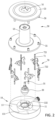
- a rotatable sprinkler mainly comprises a base 10 and a rotation element 50 that rotates relative to the base 10.
- the appearance of the carrousel is shown, and different appearance styles can also be designed as needed.
- the rotation element 50 comprises a hollow column 52 and a turntable 53 disposed on the top of the column 52 and away from the base 10.
- the internal space of the column 52 is connected with the outlet 51 of the turntable 53.
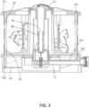
- the drive part 30 as a driving source is further disposed between the base 10 and the column 52.
- the drive part 30 is also a hollow column structure, the bottom of which is provided with an impeller disposed coaxially with a hollow column of a drive part 30.
- One end of the drive part 30 away from the impeller is used as the water outlet end 31 and is engaged inside the column 52 of the rotation element 50, and the water flow of the base 10 is led into the inner space of the column 52 and discharged from the outlet 51 of the turntable 53.
- the water flow drives the impeller to rotate while driving the turntable 53, so that the rotation element 50 as a whole rotates relative to the base 10.
- the driving source may also be such that the rotation element 50 is rotated relative to the base 10 through the motor, and the water source may be directly connected with the inside of the cylinder 52 of the rotation element 50 without passing through the base 10.
- the number of outlets 51 may be plural, and they are respectively disposed at any position on the surface of the rotation element 50 and connected with the water source inside the column 52.
- the outlet 51 may also be provided with a nozzle structure to generate a water flow type such as a high pressure water column or a water mist.
- the inside of the rotation element 50 may also be provided with a valve to control at least one outlet 51 connected with the water flow in the hollow column 52, so as to change the spraying time interval of the plural outlets 51, while collocating with the music rhythm or sound and light effect.
- the turntable 53 has the appearance of a tent
- the decorative unit 70 has the appearance of a carrousel
- the decorative unit 70 is installed in the middle section of the support 71
- the support 71 is an elongated shape and has two positioning ends 721 and 722 away from each other.
- the turntable53 of the rotation element 50 is outwardly extended and disposed with the positioning groove 56 which corresponds to the number of the decorative unit 70, the opening of the positioning groove 56 is towards the base 10, the bottom of the rotation element 50 is provided with the chassis mounted on the base 10, and the chassis is provided with the guiding groove 55 corresponding to the position of the positioning groove 56.
- the inside of the guiding groove 55 is a perforation that can be connected with the space between the chassis and base10.
- the positioning end 721 of the support 71 is inserted into the positioning groove 56, and the positioning end 722 passes through the guiding groove 55 to be in contact with the bottom surface 13 of the base 10. Therefore, the decorative unit 70 is installed between the rotation element 50 and the base 10 and rotates together with the rotation element 50.
- the bottom surface 13 of the base 10 further comprises a continuous curved surface, and the curved part defines a plurality of low part 131 and a plurality of high part 132, and the low part 131 and the high part 132 are disposed at equal angular intervals by taking the drive part 30 as the axle center, and the number of curved surfaces is equivalent to the number of the decorative unit 70.
- the depth of the positioning groove 56 is at least greater than the vertical height difference between the low part 131 and the high part 132 on the bottom surface 13. Therefore, the support 71 can move up and down between the end of the positioning groove 56 and the bottom surface 13.
- the rotatable sprinkler of the present embodiment is suitable for being placed on the open grassland as a rotatable sprinkler and a decorative unit.
- the number of curved surfaces may also be the factor or multiple of the number of the decorative unit 70
- the bottom surface of the base 10 13 can also contain the planes, so that a plurality of decorative unit 70 are located at different heights relative to the chassis of the rotation element 50.
- a part of the support can be disposed on the rotation element through other positioning way (e.g., the axle center), the main body of the support has a branch, and the free end of the branch is used as the positioning end (i.e., corresponding to the positioning end 722 in the previous embodiment) in contact with the bottom surface of the base.
- the support can also rotate with the rotation element relative to the base, and the continuous curved surface of the base can push against the branch, so that the support swings along the axle center, and also it can generates the dynamic appearance that the decorative unit rotates and jumps up and down.
- the rotation element is located between the decorative unit and the base. In this horizontal landscaping, the position of the base and the rotation element is relatively low, which can highlight the appearance of the decorative unit at a high position.
Landscapes
- Nozzles (AREA)
- Special Spraying Apparatus (AREA)
Claims (7)
- Drehbarer Sprinkler, der eine Basis (10) und ein Rotationselement (50) umfasst, das sich relativ zur Basis (10) dreht, wobei das Rotationselement (50) einen Auslass (51) umfasst, der mit einer Wasserquelle verbunden ist, und wobei das Rotationselement (50) eine hohle Säule (52) und eine Drehscheibe (53) umfasst, die an der oberen Seite der Säule (52) angeordnet ist, dadurch gekennzeichnet, dassder drehbare Sprinkler ferner mindestens eine Dekorationseinheit (70) umfasst, die zwischen der Drehscheibe (53) und der Basis (10) angeordnet ist und einen Träger (71) umfasst, der sich synchron mit dem Rotationselement (50) dreht, wobei ein freies Ende des Trägers (71) in Kontakt mit einer Bodenfläche (13) der Basis (10) steht, wobei die Bodenfläche (13) eine kontinuierlich gekrümmte Oberfläche ist und mindestens einen niedrigen Teil (131) und mindestens einen hohen Teil (132) definiert; undein Ende des Trägers (71) an der Drehscheibe (53) des Rotationselements (50) angeordnet ist, wobei die Bodenfläche (13) der Basis (10) in Kontakt mit dem freien Ende des Trägers (71) steht und so konfiguriert ist, dass sie den Träger (71) dazu antreibt, sich relativ zu der Drehscheibe (53) auf und ab zu bewegen, wenn der Träger (71) zusammen mit dem Rotationselement (50) gedreht wird.
- Drehbarer Sprinkler nach Anspruch 1, bei welchem das Rotationselement (50) in einer Antriebsquelle angeordnet ist.
- Drehbarer Sprinkler nach Anspruch 1, bei welchem die Basis (10) mit der Wasserquelle verbunden ist und ein Wassereinlass (11) des Rotationselements (50) mit der Innenseite der Basis (10) verbunden ist.
- Drehbarer Sprinkler nach Anspruch 1, bei welchem der Auslass (51) in dem Rotationselement (50) von der Seite der Basis (10) weg angeordnet ist.
- Drehbarer Sprinkler nach Anspruch 1, bei welchem das Rotationselement (50) zwischen dem Dekorationseinheit (70) und der Basis (10) angeordnet ist.
- Drehbarer Sprinkler nach Anspruch 1, bei welchem sich ein Teil des Trägers (71) in dem Rotationselement (50) befindet.
- Drehbarer Sprinkler nach Anspruch 1, bei welchem eine Anzahl der niedrigen und hohen Teile der kontinuierlich gekrümmten Oberfläche einer Anzahl von Dekorationseinheiten (70) entspricht.
Priority Applications (1)
| Application Number | Priority Date | Filing Date | Title |
|---|---|---|---|
| EP20152052.5A EP3851201B1 (de) | 2020-01-15 | 2020-01-15 | Drehbarer sprinkler |
Applications Claiming Priority (1)
| Application Number | Priority Date | Filing Date | Title |
|---|---|---|---|
| EP20152052.5A EP3851201B1 (de) | 2020-01-15 | 2020-01-15 | Drehbarer sprinkler |
Publications (3)
| Publication Number | Publication Date |
|---|---|
| EP3851201A1 EP3851201A1 (de) | 2021-07-21 |
| EP3851201B1 true EP3851201B1 (de) | 2024-10-02 |
| EP3851201C0 EP3851201C0 (de) | 2024-10-02 |
Family
ID=69172749
Family Applications (1)
| Application Number | Title | Priority Date | Filing Date |
|---|---|---|---|
| EP20152052.5A Active EP3851201B1 (de) | 2020-01-15 | 2020-01-15 | Drehbarer sprinkler |
Country Status (1)
| Country | Link |
|---|---|
| EP (1) | EP3851201B1 (de) |
Family Cites Families (4)
| Publication number | Priority date | Publication date | Assignee | Title |
|---|---|---|---|---|
| US4073438A (en) * | 1976-09-03 | 1978-02-14 | Nelson Irrigation Corporation | Sprinkler head |
| GB8404490D0 (en) * | 1984-02-21 | 1984-03-28 | Osmond D R C | Water sprinklers for lawns &c |
| US6991362B1 (en) * | 1998-04-02 | 2006-01-31 | Seaman Anthony E | Agitators for wave-making or mixing as for tanks, and pumps and filters |
| US20100065657A1 (en) * | 2008-09-12 | 2010-03-18 | Ping-Chuan Lee | Sprayer Structure |
-
2020
- 2020-01-15 EP EP20152052.5A patent/EP3851201B1/de active Active
Also Published As
| Publication number | Publication date |
|---|---|
| EP3851201A1 (de) | 2021-07-21 |
| EP3851201C0 (de) | 2024-10-02 |
Similar Documents
| Publication | Publication Date | Title |
|---|---|---|
| US7748646B2 (en) | Gear driven sprinkler with top turbine | |
| US20090108099A1 (en) | Rotary Stream Sprinkler Nozzle with Offset Flutes | |
| US9764338B2 (en) | Nozzle adjustment member for sprinkler | |
| US9808813B1 (en) | Rotary stream sprinkler nozzle with offset flutes | |
| US7726587B2 (en) | Rotary irrigation sprinkler nozzle | |
| US10137383B2 (en) | Lawn ornament having fluid and/or wind driven inner and outer frames | |
| US10688519B2 (en) | Robotic nozzle | |
| US6343749B1 (en) | Mobile drip irrigation system | |
| WO2006060465A2 (en) | Intelligent sprinkler irrigation system | |
| US5297979A (en) | Bubble maker | |
| US20200156087A1 (en) | Multiple Nozzle System | |
| US8366020B2 (en) | Sprinkler device | |
| US20100243762A1 (en) | Irrigation Nozzle With Hydrofoil | |
| EP3851201B1 (de) | Drehbarer sprinkler | |
| US11253876B2 (en) | Rotatable sprinkler | |
| US3944139A (en) | Moisturizing apparatus for use with wind machines | |
| KR20230114089A (ko) | 방제장치용 노즐어셈블리 | |
| JP5345608B2 (ja) | 噴水装置 | |
| US9221065B1 (en) | Helical water distribution restrictor | |
| US1618538A (en) | Rotating sprinkler | |
| US20130292494A1 (en) | Garden sprayer | |
| US20110186658A1 (en) | Irrigation system and nozzle assembly and methods thereof | |
| US2859064A (en) | Rotary square lawn sprinkler | |
| US5630551A (en) | In-ground reciprocating sprinkler | |
| RU2317862C1 (ru) | Насадок дождевального агрегата |
Legal Events
| Date | Code | Title | Description |
|---|---|---|---|
| PUAI | Public reference made under article 153(3) epc to a published international application that has entered the european phase |
Free format text: ORIGINAL CODE: 0009012 |
|
| STAA | Information on the status of an ep patent application or granted ep patent |
Free format text: STATUS: REQUEST FOR EXAMINATION WAS MADE |
|
| 17P | Request for examination filed |
Effective date: 20210608 |
|
| AK | Designated contracting states |
Kind code of ref document: A1 Designated state(s): AL AT BE BG CH CY CZ DE DK EE ES FI FR GB GR HR HU IE IS IT LI LT LU LV MC MK MT NL NO PL PT RO RS SE SI SK SM TR |
|
| STAA | Information on the status of an ep patent application or granted ep patent |
Free format text: STATUS: EXAMINATION IS IN PROGRESS |
|
| 17Q | First examination report despatched |
Effective date: 20220503 |
|
| GRAP | Despatch of communication of intention to grant a patent |
Free format text: ORIGINAL CODE: EPIDOSNIGR1 |
|
| STAA | Information on the status of an ep patent application or granted ep patent |
Free format text: STATUS: GRANT OF PATENT IS INTENDED |
|
| INTG | Intention to grant announced |
Effective date: 20240424 |
|
| GRAS | Grant fee paid |
Free format text: ORIGINAL CODE: EPIDOSNIGR3 |
|
| GRAA | (expected) grant |
Free format text: ORIGINAL CODE: 0009210 |
|
| STAA | Information on the status of an ep patent application or granted ep patent |
Free format text: STATUS: THE PATENT HAS BEEN GRANTED |
|
| AK | Designated contracting states |
Kind code of ref document: B1 Designated state(s): AL AT BE BG CH CY CZ DE DK EE ES FI FR GB GR HR HU IE IS IT LI LT LU LV MC MK MT NL NO PL PT RO RS SE SI SK SM TR |
|
| REG | Reference to a national code |
Ref country code: GB Ref legal event code: FG4D |
|
| REG | Reference to a national code |
Ref country code: CH Ref legal event code: EP |
|
| REG | Reference to a national code |
Ref country code: IE Ref legal event code: FG4D |
|
| REG | Reference to a national code |
Ref country code: DE Ref legal event code: R096 Ref document number: 602020038554 Country of ref document: DE |
|
| U01 | Request for unitary effect filed |
Effective date: 20241010 |
|
| U07 | Unitary effect registered |
Designated state(s): AT BE BG DE DK EE FI FR IT LT LU LV MT NL PT RO SE SI Effective date: 20241030 |
|
| U20 | Renewal fee for the european patent with unitary effect paid |
Year of fee payment: 6 Effective date: 20250130 |
|
| PG25 | Lapsed in a contracting state [announced via postgrant information from national office to epo] |
Ref country code: HR Free format text: LAPSE BECAUSE OF FAILURE TO SUBMIT A TRANSLATION OF THE DESCRIPTION OR TO PAY THE FEE WITHIN THE PRESCRIBED TIME-LIMIT Effective date: 20241002 Ref country code: IS Free format text: LAPSE BECAUSE OF FAILURE TO SUBMIT A TRANSLATION OF THE DESCRIPTION OR TO PAY THE FEE WITHIN THE PRESCRIBED TIME-LIMIT Effective date: 20250202 |
|
| PG25 | Lapsed in a contracting state [announced via postgrant information from national office to epo] |
Ref country code: ES Free format text: LAPSE BECAUSE OF FAILURE TO SUBMIT A TRANSLATION OF THE DESCRIPTION OR TO PAY THE FEE WITHIN THE PRESCRIBED TIME-LIMIT Effective date: 20241002 |
|
| PG25 | Lapsed in a contracting state [announced via postgrant information from national office to epo] |
Ref country code: NO Free format text: LAPSE BECAUSE OF FAILURE TO SUBMIT A TRANSLATION OF THE DESCRIPTION OR TO PAY THE FEE WITHIN THE PRESCRIBED TIME-LIMIT Effective date: 20250102 |
|
| PG25 | Lapsed in a contracting state [announced via postgrant information from national office to epo] |
Ref country code: GR Free format text: LAPSE BECAUSE OF FAILURE TO SUBMIT A TRANSLATION OF THE DESCRIPTION OR TO PAY THE FEE WITHIN THE PRESCRIBED TIME-LIMIT Effective date: 20250103 |
|
| PG25 | Lapsed in a contracting state [announced via postgrant information from national office to epo] |
Ref country code: PL Free format text: LAPSE BECAUSE OF FAILURE TO SUBMIT A TRANSLATION OF THE DESCRIPTION OR TO PAY THE FEE WITHIN THE PRESCRIBED TIME-LIMIT Effective date: 20241002 Ref country code: CZ Free format text: LAPSE BECAUSE OF FAILURE TO SUBMIT A TRANSLATION OF THE DESCRIPTION OR TO PAY THE FEE WITHIN THE PRESCRIBED TIME-LIMIT Effective date: 20241002 |
|
| PG25 | Lapsed in a contracting state [announced via postgrant information from national office to epo] |
Ref country code: RS Free format text: LAPSE BECAUSE OF FAILURE TO SUBMIT A TRANSLATION OF THE DESCRIPTION OR TO PAY THE FEE WITHIN THE PRESCRIBED TIME-LIMIT Effective date: 20250102 |
|
| PG25 | Lapsed in a contracting state [announced via postgrant information from national office to epo] |
Ref country code: SM Free format text: LAPSE BECAUSE OF FAILURE TO SUBMIT A TRANSLATION OF THE DESCRIPTION OR TO PAY THE FEE WITHIN THE PRESCRIBED TIME-LIMIT Effective date: 20241002 |
|
| PG25 | Lapsed in a contracting state [announced via postgrant information from national office to epo] |
Ref country code: SK Free format text: LAPSE BECAUSE OF FAILURE TO SUBMIT A TRANSLATION OF THE DESCRIPTION OR TO PAY THE FEE WITHIN THE PRESCRIBED TIME-LIMIT Effective date: 20241002 |
|
| PLBE | No opposition filed within time limit |
Free format text: ORIGINAL CODE: 0009261 |
|
| STAA | Information on the status of an ep patent application or granted ep patent |
Free format text: STATUS: NO OPPOSITION FILED WITHIN TIME LIMIT |
|
| REG | Reference to a national code |
Ref country code: CH Ref legal event code: PL |
|
| 26N | No opposition filed |
Effective date: 20250703 |
|
| PG25 | Lapsed in a contracting state [announced via postgrant information from national office to epo] |
Ref country code: MC Free format text: LAPSE BECAUSE OF FAILURE TO SUBMIT A TRANSLATION OF THE DESCRIPTION OR TO PAY THE FEE WITHIN THE PRESCRIBED TIME-LIMIT Effective date: 20241002 |
|
| GBPC | Gb: european patent ceased through non-payment of renewal fee |
Effective date: 20250115 |
|
| PG25 | Lapsed in a contracting state [announced via postgrant information from national office to epo] |
Ref country code: GB Free format text: LAPSE BECAUSE OF NON-PAYMENT OF DUE FEES Effective date: 20250115 |
|
| PG25 | Lapsed in a contracting state [announced via postgrant information from national office to epo] |
Ref country code: CH Free format text: LAPSE BECAUSE OF NON-PAYMENT OF DUE FEES Effective date: 20250131 |
|
| PG25 | Lapsed in a contracting state [announced via postgrant information from national office to epo] |
Ref country code: IE Free format text: LAPSE BECAUSE OF NON-PAYMENT OF DUE FEES Effective date: 20250115 |