EP3851229A1 - Hub- und zentriersystem für eine raddrehmaschine - Google Patents
Hub- und zentriersystem für eine raddrehmaschine Download PDFInfo
- Publication number
- EP3851229A1 EP3851229A1 EP21151099.5A EP21151099A EP3851229A1 EP 3851229 A1 EP3851229 A1 EP 3851229A1 EP 21151099 A EP21151099 A EP 21151099A EP 3851229 A1 EP3851229 A1 EP 3851229A1
- Authority
- EP
- European Patent Office
- Prior art keywords
- wheel
- centering system
- lifting
- rollers
- wheel lathe
- Prior art date
- Legal status (The legal status is an assumption and is not a legal conclusion. Google has not performed a legal analysis and makes no representation as to the accuracy of the status listed.)
- Withdrawn
Links
- 230000003993 interaction Effects 0.000 claims description 3
- 230000006835 compression Effects 0.000 claims 1
- 238000007906 compression Methods 0.000 claims 1
- 238000012545 processing Methods 0.000 abstract description 12
- 238000005096 rolling process Methods 0.000 abstract description 9
- 238000009434 installation Methods 0.000 abstract description 3
- 238000005520 cutting process Methods 0.000 description 8
- 238000003754 machining Methods 0.000 description 6
- 238000005259 measurement Methods 0.000 description 5
- 230000001360 synchronised effect Effects 0.000 description 2
- SEPPVOUBHWNCAW-FNORWQNLSA-N (E)-4-oxonon-2-enal Chemical compound CCCCCC(=O)\C=C\C=O SEPPVOUBHWNCAW-FNORWQNLSA-N 0.000 description 1
- LLBZPESJRQGYMB-UHFFFAOYSA-N 4-one Natural products O1C(C(=O)CC)CC(C)C11C2(C)CCC(C3(C)C(C(C)(CO)C(OC4C(C(O)C(O)C(COC5C(C(O)C(O)CO5)OC5C(C(OC6C(C(O)C(O)C(CO)O6)O)C(O)C(CO)O5)OC5C(C(O)C(O)C(C)O5)O)O4)O)CC3)CC3)=C3C2(C)CC1 LLBZPESJRQGYMB-UHFFFAOYSA-N 0.000 description 1
- 238000013459 approach Methods 0.000 description 1
- 238000013016 damping Methods 0.000 description 1
- 230000007547 defect Effects 0.000 description 1
- 239000000428 dust Substances 0.000 description 1
- 230000008030 elimination Effects 0.000 description 1
- 238000003379 elimination reaction Methods 0.000 description 1
- 125000000524 functional group Chemical group 0.000 description 1
- 239000000314 lubricant Substances 0.000 description 1
- 238000012423 maintenance Methods 0.000 description 1
- 238000004519 manufacturing process Methods 0.000 description 1
- 238000005457 optimization Methods 0.000 description 1
- 238000002360 preparation method Methods 0.000 description 1
- 230000009467 reduction Effects 0.000 description 1
- 238000012958 reprocessing Methods 0.000 description 1
- 239000000779 smoke Substances 0.000 description 1
- 238000012546 transfer Methods 0.000 description 1
Images



Classifications
-
- B—PERFORMING OPERATIONS; TRANSPORTING
- B23—MACHINE TOOLS; METAL-WORKING NOT OTHERWISE PROVIDED FOR
- B23B—TURNING; BORING
- B23B5/00—Turning-machines or devices specially adapted for particular work; Accessories specially adapted therefor
- B23B5/28—Turning-machines or devices specially adapted for particular work; Accessories specially adapted therefor for turning wheels or wheel sets or cranks thereon, i.e. wheel lathes
-
- B—PERFORMING OPERATIONS; TRANSPORTING
- B23—MACHINE TOOLS; METAL-WORKING NOT OTHERWISE PROVIDED FOR
- B23B—TURNING; BORING
- B23B5/00—Turning-machines or devices specially adapted for particular work; Accessories specially adapted therefor
- B23B5/28—Turning-machines or devices specially adapted for particular work; Accessories specially adapted therefor for turning wheels or wheel sets or cranks thereon, i.e. wheel lathes
- B23B5/32—Turning-machines or devices specially adapted for particular work; Accessories specially adapted therefor for turning wheels or wheel sets or cranks thereon, i.e. wheel lathes for reconditioning wheel sets without removing same from the vehicle; Underfloor wheel lathes for railway vehicles
Definitions
- the invention relates to the field of machine tools, namely, wheel lathe without rolling out with a lifting centering system, intended for installation in a pit below the rail head in indoor heated rooms, and can be used for lifting and centering wheel sets and brake discs of rolling stock when processing the rolling surface and with a maximum load of up to 40 tons per axle.
- a wheel lathe with a system comprising two symmetrically arranged balancers with spindle rollers fixing the cutting tools, and two drive posts made with the possibility of vertical movement and acting on the balancers to bring the cutting tool into interaction with the wheel being machined (see patent CN206296458U , cl. B23B 5/32, published. 04.07.2017).
- the main disadvantages of the known device are the complexity of manufacture and a relatively short service life due to the rapid failure of the drive racks due to large values of horizontal loads.
- a technical problem is the elimination of these disadvantages and the creation of a robust and easy-to-use machine with a compact lifting centering system.
- the technical result consists in increasing the strength and expanding the possibilities of varying the processing modes due to the developed lifting centering system.
- the problem is solved, and the technical result is achieved by the fact that in a wheel lathe containing a lifting centering system, including two symmetrically located balancers with spindle rollers, and two drive racks, made with the possibility of vertical movement and impact on the balancers to transfer rotary motion to the processed wheel, each rack is made in the form of a trapezoidal screw connected to the drive motor shaft and mounted on the specified screw by means of an internal thread of the quill, which is fixed against rotation and is provided with an end support with push rollers from above, and the corresponding balancer is provided from below with a cam plate, which is acted upon by said push rollers.
- Each balancer is preferably additionally equipped with a hydraulic cylinder to ensure that the broadcast roller is pressed against the wheel.
- Each rack is preferably equipped with its own independent drive motor with encoder.
- Each quill is preferably provided with keys (wedges) to prevent it from rotating.
- the trapezoidal screw is preferably secured to the base of the strut with a radial thrust bearing.
- a wheel lathe without roll-out is a special machine designed for the processing of rolling surfaces of wheels and brake discs, which does not require dismantling of wheel sets, which are subject to normal wear and deformation that occurs due to the rail-wheel contact.
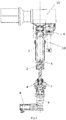
- the proposed lifting centering system of the machine consists of two quills 1, symmetrical about the X axis, with an internal thread on a nut 2, each of which is installed in a sleeve 3 and is set in vertical motion by a trapezoidal screw 4 with a stopper 5.
- the screw 4 is installed in the support 6, and the vertical load is supported by the combined thrust-radial bearing 7 on the screw head 4. Due to the appropriate choice of the ratio between the diameter and the pitch of the screw 4, the threaded pair is self-locking in any position.
- the screw 4 is driven by being connected to the shaft of an independent drive motor 8 (brushless synchronous or asynchronous or stepper motor with a power of 1 to 3 kW) of the appropriate size with an absolute encoder through a gearbox 9, which accurately determines the position of the system at any time.
- an independent drive motor 8 brushless synchronous or asynchronous or stepper motor with a power of 1 to 3 kW
- gearbox 9 which accurately determines the position of the system at any time.
- each quill 1 On the opposite side, at the end of each quill 1, there is an end support 11 with a pair of pusher rollers 12 of the corresponding size, mounted on the axle 13.
- the push rollers 12 are in contact with the cam plate 14, which is fixed to the balancers 15.
- the function of the plate 14 is to convert the vertical movement of the quill 1 into the rotational movement of the balance beams 15.
- the balancers 15 are equipped with rotary rollers 16, through the interaction of which with the wheel 17 to be processed, rotational movement is transmitted to it.
- Each balancer 15 is additionally equipped with a hydraulic cylinder 18 that pushes the rotary roller 16 against the wheel 17, thus ensuring traction for turning operations.
- the immobility of the train axis during the operation of the machine is guaranteed by the support of the axle boxes and load drives.
- the fastening of the wheel 17 occurs due to the friction of the push rollers 12 on the rolling surface.
- the use of these pusher rollers 12 increases the coefficient of friction, thereby increasing the frictional force and therefore the cutting power.
- the machine can additionally be equipped with a floating or damping system along two axes (compensation) so that deformations of the rolling surface do not become forces applied to the axis; this ensures that the machining is free of ovality.
- twin tools depending on the power consumption, avoids problems with long chips and provides better machining on external and internal roundings.
- the cutting edge of the tool is located along the axis of the wheel being machined, so the cutting angle does not depend on the diameter of the wheel being machined, which ensures optimal cutting power.
- the presence of a diameter gauge on the saddle allows measurements to be carried out at any point of the profile, which provides significant advantages in terms of accuracy and the possibility of measuring the diameter on different types of profiles with a control circle at different distances from the inner surface of the wheel.
- the machine is installed below the zero rail, which is more economical in terms of installation and improves ergonomics.
- the proposed lifting centering system of the machine works as follows.
- the wheel lathe with the proposed lifting centering system is located in the center of the pit, and connected through the movable system 19 of the rails to the workshop track 20.
- the working cycle takes place with the participation of the operator.
- the operator is in a protected area in front of the working area, from where he controls the processing and preparation phases using the operator panel.
- the phases of the cycle when the train is stopped, the operator has access to the top of the machine and therefore to the outer parts of the bogie in order to carry out the manual operations necessary to clamp or unclamp the axle box of the wheelset.
- the operator has access to the work area, which can be accessed by unlocking and opening part of the guard 21.
- a system of rails 19 is present at the entrance and exit of the lathe, connecting it to the track 20 of the workshop.
- a retractable rail system housed in a fixed rail system allows the vehicle to be positioned over the center of the machine. Once the wheelset is clamped, the retractable rail system provides a complete machining cycle, freeing up the working area.
- the automatic lift system (b) will center the vehicle and raise the wheelset by pushing and touching the synchronized lift rollers.
- the operator will have to install two base plates and corresponding adapters under the axleboxes of the wheelset. These base plates are lifted by lifting two jacks, which are driven by motors and adjusted by operator intervention: the presence of contact between the plates and the axle boxes is monitored by appropriate sensors. After contact with the axle boxes has been achieved, the lifting system of the parts is removed and the weight of the part is completely transferred to the jacking system: the support of the piece weight is due to the irreversibility of the jack system.
- the operator can enhance the grip of the part using an additional clamping system; therefore, a number of gripping elements come into contact with axle boxes, which approach and are brought into position in an auxiliary way, but always under the control of the operator.
- the working blocks are two longitudinal slides, which move along high-precision rolling guides, are driven by screws rotated by numerical control (CNC) servomotors: they are equipped with groups of tools and systems for measuring and processing the workpiece (c). These groups are necessary to determine the position of the workpiece and set the reference "zero" for subsequent processing operations.
- the wear condition of the wheel profiles and possibly the brake discs, if they are to be machined, is measured in order to select the optimum cutting conditions.
- the rotation of the part occurs due to the traction of motorized rotary rollers 16, which are appropriately pressed against the surface of the wheels 17: they are able to compensate for the reduction in diameter due to machining and possible surface defects of the machined wheels.
- the tool groups are also CNC controlled and allow the required tool path and wheel reprofiling by coordinating the movement with the longitudinal carriages.
- the machine is capable of reprocessing a worn wheelset and brake discs, if any. To do this, it is necessary to know the geometry of the brake discs and the overall dimensions of the adjacent units near the axle of the wheelset in order to study the machining process and, if necessary, adjust special tools. After processing, a measurement cycle is performed to determine if processing is correct and, if necessary, generate a report.
- the operator begins the phase of unloading the wheelset. First, additional clamps are manually retracted, then the lifting rollers come into contact with the wheel and lift the axle boxes from the support plates. The slide rails are brought to the center position, the base plates are lowered and the lifting rollers are lowered to mount the wheelset on the slide rails. At this moment, the semaphore signals the possibility of safe movement of the vehicle.
- the auxiliary groups (d) supplied with the machine can perform various functions - these can be: suction unit for removing generated when handling smoke and dust in the work area, a grinder under the work area to reduce the size of chips, a chip removal device to discharge the chips from the sump into a collection box, a hydraulic and lubrication center to generate the required power and distribute the correct amount of lubricant at the points and in the correct modes , a cabinet kit with gripper adapters, tools and cam plates, and an optional printer and / or computer for any remote connections and print run-time measurement report.
- the expected cycle time is 35 minutes, taking into account rigging (selection of attachments and rigging), wheelset clamping, wheelset measurement, reprofiling with one pass of 5mm on the tread surface, final measurement, wheelset unloading.
- the advantages of the proposed lifting centering system of the wheel lathe are to increase the compactness, eliminate horizontal forces on the axles to increase strength, provide the possibility of modulating the force (and, therefore, the engine torque) for lifting the train using the balance bar; optimization of the force (engine torque) and, consequently, the installed power by selecting the shape of the cam plate, minimizing vertical travel and increasing rigidity, making it possible to adjust the cam plate profile to perform various passes without changing other components of the overall system (in this case, the single-sided cam system spindle compensation system, which avoids loads due to possible deviations from the roundness of the wheels of the mechanical system).
Landscapes
- Engineering & Computer Science (AREA)
- Mechanical Engineering (AREA)
- Turning (AREA)
Applications Claiming Priority (1)
| Application Number | Priority Date | Filing Date | Title |
|---|---|---|---|
| RU2020100937A RU2722496C1 (ru) | 2020-01-14 | 2020-01-14 | Подъемно-центрирующая система колесотокарного станка |
Publications (1)
| Publication Number | Publication Date |
|---|---|
| EP3851229A1 true EP3851229A1 (de) | 2021-07-21 |
Family
ID=71067342
Family Applications (1)
| Application Number | Title | Priority Date | Filing Date |
|---|---|---|---|
| EP21151099.5A Withdrawn EP3851229A1 (de) | 2020-01-14 | 2021-01-12 | Hub- und zentriersystem für eine raddrehmaschine |
Country Status (5)
| Country | Link |
|---|---|
| EP (1) | EP3851229A1 (de) |
| CN (1) | CN214185251U (de) |
| DE (1) | DE202021107053U1 (de) |
| RU (1) | RU2722496C1 (de) |
| TR (1) | TR202017159U5 (de) |
Cited By (1)
| Publication number | Priority date | Publication date | Assignee | Title |
|---|---|---|---|---|
| CN116571770A (zh) * | 2023-05-31 | 2023-08-11 | 邯郸钢铁集团有限责任公司 | 一种钢轨uf轧辊高精度车削方法 |
Families Citing this family (1)
| Publication number | Priority date | Publication date | Assignee | Title |
|---|---|---|---|---|
| CN113927050B (zh) * | 2021-10-23 | 2022-11-29 | 济南泰成科技有限公司 | 一种全电动固定式不落轮车轮车床 |
Citations (4)
| Publication number | Priority date | Publication date | Assignee | Title |
|---|---|---|---|---|
| JPS5395389A (en) * | 1977-01-31 | 1978-08-21 | Kawasaki Heavy Ind Ltd | Apparatus for planing wheels attached to railway vehicles |
| DE2937751A1 (de) * | 1979-09-19 | 1981-04-02 | Wilhelm Hegenscheidt, Gmbh, 5140 Erkelenz | Unterflurradsatzdrehmaschine |
| RU2229995C2 (ru) * | 2001-12-06 | 2004-06-10 | Сыченков Владимир Васильевич | Способ базирования колесной пары, базирующее приспособление и устройство для позиционирования колесной пары, а также комплекс для измерения нормируемых линейных размеров колесных пар |
| CN206296458U (zh) | 2016-11-15 | 2017-07-04 | 北京北一机床股份有限公司 | 一种数控不落轮镟床摩擦轮独立随动装置 |
Family Cites Families (5)
| Publication number | Priority date | Publication date | Assignee | Title |
|---|---|---|---|---|
| RU2107586C1 (ru) * | 1996-03-04 | 1998-03-27 | Акционерное общество "Рязанское специальное конструкторское бюро станкостроения" | Станок для обточки колесных пар без выкатки для восстановления профиля бандажа железнодорожных колес |
| DE102005001220B4 (de) * | 2005-01-10 | 2007-12-13 | Hegenscheidt-Mfd Gmbh & Co. Kg | Unterflurradsatzdrehmaschine zum Bearbeiten von Radsätzen für Eisenbahnfahrzeuge |
| RU51545U1 (ru) * | 2005-10-26 | 2006-02-27 | Открытое акционерное общество "Станкон" | Подрельсовый колесотокарный станок |
| DE102006055299B4 (de) * | 2006-11-23 | 2009-04-02 | Hegenscheidt-Mfd Gmbh & Co. Kg | Portal-Radsatzdrehmaschine |
| RU66997U1 (ru) * | 2007-04-04 | 2007-10-10 | Открытое акционерное общество "Станкон" | Станок колесотокарный проходной с чпу |
-
2020
- 2020-01-14 RU RU2020100937A patent/RU2722496C1/ru active
- 2020-10-27 TR TR2020/17159U patent/TR202017159U5/tr unknown
- 2020-11-20 CN CN202022721856.1U patent/CN214185251U/zh active Active
-
2021
- 2021-01-12 DE DE202021107053.6U patent/DE202021107053U1/de not_active Expired - Lifetime
- 2021-01-12 EP EP21151099.5A patent/EP3851229A1/de not_active Withdrawn
Patent Citations (4)
| Publication number | Priority date | Publication date | Assignee | Title |
|---|---|---|---|---|
| JPS5395389A (en) * | 1977-01-31 | 1978-08-21 | Kawasaki Heavy Ind Ltd | Apparatus for planing wheels attached to railway vehicles |
| DE2937751A1 (de) * | 1979-09-19 | 1981-04-02 | Wilhelm Hegenscheidt, Gmbh, 5140 Erkelenz | Unterflurradsatzdrehmaschine |
| RU2229995C2 (ru) * | 2001-12-06 | 2004-06-10 | Сыченков Владимир Васильевич | Способ базирования колесной пары, базирующее приспособление и устройство для позиционирования колесной пары, а также комплекс для измерения нормируемых линейных размеров колесных пар |
| CN206296458U (zh) | 2016-11-15 | 2017-07-04 | 北京北一机床股份有限公司 | 一种数控不落轮镟床摩擦轮独立随动装置 |
Cited By (1)
| Publication number | Priority date | Publication date | Assignee | Title |
|---|---|---|---|---|
| CN116571770A (zh) * | 2023-05-31 | 2023-08-11 | 邯郸钢铁集团有限责任公司 | 一种钢轨uf轧辊高精度车削方法 |
Also Published As
| Publication number | Publication date |
|---|---|
| DE202021107053U1 (de) | 2022-07-05 |
| RU2722496C1 (ru) | 2020-06-01 |
| CN214185251U (zh) | 2021-09-14 |
| TR202017159U5 (tr) | 2021-03-22 |
Similar Documents
| Publication | Publication Date | Title |
|---|---|---|
| JP5462236B2 (ja) | 鉄道車輪を加工する方法と機械 | |
| US3513517A (en) | Machining of large hollow cylindrical workpieces | |
| EP3851229A1 (de) | Hub- und zentriersystem für eine raddrehmaschine | |
| US4993193A (en) | Railroad vehicle for reprofiling at least one rail of a railroad track | |
| CN106735430B (zh) | 一种大型锅炉用锅筒和集箱高速数控钻床 | |
| CN113028995A (zh) | 用于检测中大型工件表面跳动度的自动检测装置 | |
| JP7727306B2 (ja) | 中空軸の穿孔・傾斜圧延・一体成形装置 | |
| CN102091812B (zh) | 重型曲轴铣架位加工工艺 | |
| CN101554665B (zh) | 可对多组车轮同时加工的在轨式车轮车床 | |
| RU2675329C1 (ru) | Мобильный станок для обточки колесных пар | |
| US4187600A (en) | Apparatus for machining railroad truck bolsters | |
| CN201900514U (zh) | 卧式双面数控铣端面钻中心孔机床的同轴度检测装置 | |
| US3073185A (en) | Boring mill | |
| RU2011475C1 (ru) | Станок для обработки колесных пар | |
| CN1059620C (zh) | 加工轨道车轮组用的龙门型滚过式车轮车床 | |
| CN201997963U (zh) | 卧式双面数控铣端面钻中心孔机床的工件找正装置 | |
| CN111266977A (zh) | 数控高速双砂轮架桥壳磨床 | |
| CN201579417U (zh) | 可对多组车轮同时加工的在轨式车轮车床 | |
| CN111774900B (zh) | 一种卷筒立式加工装夹装置及加工方法 | |
| US3044368A (en) | Wheel truing apparatus for railroad vehicles | |
| US3200679A (en) | Workpiece loading and unloading apparatus | |
| RU185997U1 (ru) | Мобильный станок для обточки железнодорожных колесных пар без выкатки из-под подвижного состава | |
| RU2809883C1 (ru) | Металлорежущий станок для обработки отверстия ступицы железнодорожных колес | |
| CN205520471U (zh) | 一种多维数控高速钻床 | |
| CN113134652B (zh) | 轴箱轴承综合试验台修复设备及其方法 |
Legal Events
| Date | Code | Title | Description |
|---|---|---|---|
| PUAI | Public reference made under article 153(3) epc to a published international application that has entered the european phase |
Free format text: ORIGINAL CODE: 0009012 |
|
| STAA | Information on the status of an ep patent application or granted ep patent |
Free format text: STATUS: THE APPLICATION HAS BEEN PUBLISHED |
|
| AK | Designated contracting states |
Kind code of ref document: A1 Designated state(s): AL AT BE BG CH CY CZ DE DK EE ES FI FR GB GR HR HU IE IS IT LI LT LU LV MC MK MT NL NO PL PT RO RS SE SI SK SM TR |
|
| STAA | Information on the status of an ep patent application or granted ep patent |
Free format text: STATUS: THE APPLICATION IS DEEMED TO BE WITHDRAWN |
|
| 18D | Application deemed to be withdrawn |
Effective date: 20220122 |