EP3851260B1 - Greifer für schneidvorrichtung - Google Patents
Greifer für schneidvorrichtung Download PDFInfo
- Publication number
- EP3851260B1 EP3851260B1 EP21159074.0A EP21159074A EP3851260B1 EP 3851260 B1 EP3851260 B1 EP 3851260B1 EP 21159074 A EP21159074 A EP 21159074A EP 3851260 B1 EP3851260 B1 EP 3851260B1
- Authority
- EP
- European Patent Office
- Prior art keywords
- suction
- product
- gripper
- sections
- section
- Prior art date
- Legal status (The legal status is an assumption and is not a legal conclusion. Google has not performed a legal analysis and makes no representation as to the accuracy of the status listed.)
- Active
Links
Images




Classifications
-
- B—PERFORMING OPERATIONS; TRANSPORTING
- B26—HAND CUTTING TOOLS; CUTTING; SEVERING
- B26D—CUTTING; DETAILS COMMON TO MACHINES FOR PERFORATING, PUNCHING, CUTTING-OUT, STAMPING-OUT OR SEVERING
- B26D7/00—Details of apparatus for cutting, cutting-out, stamping-out, punching, perforating, or severing by means other than cutting
- B26D7/01—Means for holding or positioning work
- B26D7/018—Holding the work by suction
-
- B—PERFORMING OPERATIONS; TRANSPORTING
- B25—HAND TOOLS; PORTABLE POWER-DRIVEN TOOLS; MANIPULATORS
- B25J—MANIPULATORS; CHAMBERS PROVIDED WITH MANIPULATION DEVICES
- B25J11/00—Manipulators not otherwise provided for
- B25J11/0045—Manipulators used in the food industry
-
- B—PERFORMING OPERATIONS; TRANSPORTING
- B25—HAND TOOLS; PORTABLE POWER-DRIVEN TOOLS; MANIPULATORS
- B25J—MANIPULATORS; CHAMBERS PROVIDED WITH MANIPULATION DEVICES
- B25J11/00—Manipulators not otherwise provided for
- B25J11/005—Manipulators for mechanical processing tasks
- B25J11/0055—Cutting
-
- B—PERFORMING OPERATIONS; TRANSPORTING
- B25—HAND TOOLS; PORTABLE POWER-DRIVEN TOOLS; MANIPULATORS
- B25J—MANIPULATORS; CHAMBERS PROVIDED WITH MANIPULATION DEVICES
- B25J15/00—Gripping heads and other end effectors
- B25J15/06—Gripping heads and other end effectors with vacuum or magnetic holding means
- B25J15/0616—Gripping heads and other end effectors with vacuum or magnetic holding means with vacuum
-
- B—PERFORMING OPERATIONS; TRANSPORTING
- B26—HAND CUTTING TOOLS; CUTTING; SEVERING
- B26D—CUTTING; DETAILS COMMON TO MACHINES FOR PERFORATING, PUNCHING, CUTTING-OUT, STAMPING-OUT OR SEVERING
- B26D7/00—Details of apparatus for cutting, cutting-out, stamping-out, punching, perforating, or severing by means other than cutting
- B26D7/06—Arrangements for feeding or delivering work of other than sheet, web, or filamentary form
- B26D7/0625—Arrangements for feeding or delivering work of other than sheet, web, or filamentary form by endless conveyors, e.g. belts
- B26D7/0633—Arrangements for feeding or delivering work of other than sheet, web, or filamentary form by endless conveyors, e.g. belts by grippers
-
- A—HUMAN NECESSITIES
- A47—FURNITURE; DOMESTIC ARTICLES OR APPLIANCES; COFFEE MILLS; SPICE MILLS; SUCTION CLEANERS IN GENERAL
- A47J—KITCHEN EQUIPMENT; COFFEE MILLS; SPICE MILLS; APPARATUS FOR MAKING BEVERAGES
- A47J43/00—Implements for preparing or holding food, not provided for in other groups of this subclass
- A47J43/18—Holding or clamping devices for supporting fowl, venison, or other meat, or vegetables, during cooking or during subsequent cutting
-
- B—PERFORMING OPERATIONS; TRANSPORTING
- B26—HAND CUTTING TOOLS; CUTTING; SEVERING
- B26D—CUTTING; DETAILS COMMON TO MACHINES FOR PERFORATING, PUNCHING, CUTTING-OUT, STAMPING-OUT OR SEVERING
- B26D7/00—Details of apparatus for cutting, cutting-out, stamping-out, punching, perforating, or severing by means other than cutting
- B26D7/01—Means for holding or positioning work
- B26D2007/011—Means for holding or positioning work by clamping claws, e.g. in high speed slicers for food products
-
- B—PERFORMING OPERATIONS; TRANSPORTING
- B26—HAND CUTTING TOOLS; CUTTING; SEVERING
- B26D—CUTTING; DETAILS COMMON TO MACHINES FOR PERFORATING, PUNCHING, CUTTING-OUT, STAMPING-OUT OR SEVERING
- B26D2210/00—Machines or methods used for cutting special materials
- B26D2210/02—Machines or methods used for cutting special materials for cutting food products, e.g. food slicers
Definitions
- the present invention relates to a gripper for gripping a product, in particular a food product.
- the gripper serves as a product holder.
- Such grippers are used, for example, in food technology in the feed area of high-performance cutting machines when a food product needs to be cut into slices.
- Rotating circular and sickle blades are used, which correspond to a cutting edge at the end of the feed area.
- the food product is usually placed in a feed device that enables the product to be fed to a cutting plane in a well-defined manner.
- an end section of the product is grasped by the gripper and held reliably.
- the product is essentially transported to the cutting plane by the feed device.
- the closer the cutting plane comes to the end section of the food the more difficult it becomes to ensure that the product is fed forward and that it is fixed in the correct position using the feed device alone.
- the product to be cut is subject to considerable transverse forces that must be reliably compensated for. These transverse forces depend primarily on the product's resistance to the penetration of the cutting blade.
- a conveyor belt is used to ensure reliable advancement of the product and its fixation, especially when if the surface of the product resting on the belt is as large as possible. Towards the end of the cutting process, this surface becomes smaller and smaller, so that the fixation of the product by the gripper becomes more and more important. On the one hand, it must ensure that the product is reliably transported to the cutting plane. On the other hand, it must ensure that the product is held securely and - depending on the application - is also pulled back to create portions with short cutting interruptions.
- the sealing section thus ensures - in addition to the sealing device - a reliable seal of the suction section from the outside, so that the suction power provided there - for example in a corresponding suction chamber - creates a negative pressure that reliably fixes the product.
- the sealing device of the first suction section can also be part of the contact surface.
- any type of vacuum pump can be considered as a pumping device.
- jet pumps also known as injectors
- a gripper with a suction device having a contact surface that can be brought into contact with a section, in particular an end section, of the product, wherein the suction device has at least a first suction section which is delimited in the radial direction by a sealing device and which is connected to a pumping device generating negative pressure, wherein the shape of the first suction section - in particular also the shape of the sealing device of the first suction section - is adaptable at least in sections to a shape of the surface of the section of the product.
- the adaptability of the first suction section means that it can adapt to the contour of the product, which has a positive effect on the tightness of the parts of the suction device that are in contact with the product. This in turn ultimately ensures improved fixation of the product.
- the suction device can consist of an elastic material at least in sections.
- the suction device can consist of an elastic material at least in sections.
- This elastic section and/or section with modifiable rigidity can be formed over a large area or only provided locally. For example, it is provided in areas that are arranged between the suction section and the outside space in order to act as a sealing device and/or to supplement it.
- Modifiable rigidity can be provided by electro-/magnetorheological units. It is also conceivable to provide elements that contain liquid and are then compressed. With a corresponding design, the gripper is pressed against the end section of the product and adapts (locally) to its shape. The shape of the suction section is then fixed, in the aforementioned examples for example by applying an electric/magnetic field or by cooling.
- a gripper which comprises a suction device having a contact surface, wherein the suction device has at least one first suction section which is delimited in the radial direction by a sealing device and which is connected to a pump device which generates a vacuum.
- the suction device is arranged to be actively or passively laterally movable at least in one plane of the contact surface.
- the suction device has several sections which are arranged to be actively or passively laterally movable at least in one plane of the contact surface. According to one embodiment, these sections are arranged to be movable separately from one another.
- the suction device is arranged to be movable by means of a deflection arrangement which comprises a fixing unit with which the lateral mobility of the suction device can be selectively influenced or controlled, in particular wherein the fixing unit is designed such that different sections of the suction device can be selectively influenced or controlled in order to enable different lateral mobility of different sections of the suction device.
- the amplitude of the gripper's movement can be limited and/or influenced by suitable stops and/or "braking” or dissipative components.
- suitable stops and/or "braking” or dissipative components For example, the use of electro-/magnetorheological elements, mechanical "brakes” or similar is conceivable.
- the components can also be designed in such a way that they ensure complete fixation of the gripper with regard to a lateral deflection movement if required.
- the lateral mobility of the gripper can, for example, provided by elastic and/or articulated devices.
- a gripper that has a suction device with a contact surface that can be brought into contact with a section, in particular an end section, of the product, wherein the suction device has at least a first suction section that is delimited in the radial direction by a sealing device and that is connected to a pumping device that generates negative pressure.
- a cooling device is provided with which the suction device and/or the product can be cooled at least in sections, in particular directly or indirectly by means of a coolant.
- the product is not only secured by the suction device, but is also secured by freezing at least in sections.
- the freezing creates an additional securing connection between the product and the suction device.
- a coolant is preferable in many cases. This can, for example, be transported to the desired locations through suitable coolant channels in the gripper. Examples of coolants that can be considered are liquid nitrogen, brine or supercooled compressed air.
- the cooling device can be designed in such a way that the suction device can be cooled in an area that extends in the radial direction at least partially, in particular completely, around the first suction section.
- the icing generated thus surrounds the first suction section at least partially and thus supports its sealing against the outside.
- this enables a practically automatic adaptation to irregularities in the product surface. achieved. Cooling or even freezing the product also increases its strength and may lead to the closing of pore spaces that can cause leakage. In contrast to mechanical gripping hooks, the product is not damaged. Increasing the product strength through freezing can make cutting the product easier and/or prevent gripping devices that mechanically engage the product from "ripping out” (see below).
- the cooling device can also be designed such that the coolant can be injected into the first suction section in order to quickly cool the relevant surfaces of the product and the gripper. Evacuating the suction section and introducing the coolant in one or more cycles increases the efficiency of the cooling.
- the cooling device can also be designed such that water can be injected into the first suction section. For example, water (or a water-air mixture) is first injected into a suction chamber or several suction chambers of the suction device. Then surfaces of the gripper facing the product are cooled, whereby the water freezes and a fixing ice is formed. The gripper can be heated (locally) to eject the end piece.
- the sealing section comprises at least one second suction section, which is limited in the radial direction by a second sealing device and which is connected to the pump device generating negative pressure.
- the second suction section thus forms a - viewed in the radial direction - at least partially seals the first suction section towards the outside. shielding functional component that develops an additional fixing and sealing effect.
- the corresponding sealing section can also be coolable, in particular it can be provided that coolant and/or water can be injected into the second suction section.
- the first and/or the second sealing device can be designed as a cutting edge, at least in sections. When the product is grasped by the gripper, such a cutting edge penetrates into the product and locally plastically deforms it.
- first and/or the second sealing device as a bead or sealing lip, at least in sections.
- a bead essentially only elastically deforms the surface of the product and also compresses it slightly.
- a sealing lip lies tightly on the product with only insignificant deformation of the product.
- sealing device depends, among other things, on the properties of the product to be gripped. If required, sealing devices of different designs can be combined in any way in a gripper in order to take the respective requirements into account.
- the first and/or the second sealing device are shaped in such a way that a local compression of the product that can be brought into contact with the sealing device can be generated.
- the first and/or the second sealing device are wedge-shaped at least in sections. It is particularly efficient if two oppositely located bevels are provided that diverge in a direction towards the product. When the product is gripped, it is compressed by the V-shaped design of the space between the slopes, which closes any pores that may be present in the product and results in good adhesion. In other words, the contact force and thus the sealing effect between the product and the contact slope is increased.
- the first suction section is divided into at least two segments by at least one wall section.
- a surface of the corresponding wall section facing the product forms part of the contact surface.
- sealing devices, claws, pins, tips, cutting edges, beads, sealing lips or similar can be provided on the surface in order to further improve the fixation. The above also applies to the sealing section, if it is provided.
- the contact surface - regardless of whether it is located in the area of the suction or sealing section, between these sections or radially outside the said sections - can have at least one suction opening in order to achieve the firmest and preferably tightest possible contact of the product with the contact surface.
- first suction sections and/or several sealing sections - possibly each with one or more second suction sections - are provided.
- these are each separated from one another by only one sealing device.
- the gripper can comprise a selectively actuatable gripping device which has at least one gripping element which is arranged in such a way that it can penetrate into the product when the gripper comes into contact with the product in the area of the contact surface and/or in an area around the contact surface.
- a corresponding actuation device can be operated mechanically, pneumatically, hydraulically or electrically.
- the gripping element is arranged in such a way that it can engage the product when the gripper comes into contact with the product in the area of the first suction section.
- Another embodiment of the gripping element provides that it is arranged in such a way that it can engage an edge area of the product when the gripper comes into contact with the product.
- the engagement can be provided in a direction oblique to the edge of the product. If particularly large transverse forces act on the product from this edge of the product - for example when a cutting knife penetrates - it is pressed against the gripping element. This has a supporting effect on the fixation.
- the pump device comprises several separate pump units. This is particularly advantageous when there are several suction sections that are to be individually and as required subjected to negative pressure. For example, it is entirely possible to couple some suction sections to a pump unit and connect other suction sections to another unit. A separate negative pressure can also be created by suitable means for setting the desired negative pressure levels in the individual sections of the suction device. Such means are, for example, valve or throttle devices. A combination of several pump units and means for pressure adjustment is also possible.
- the pumping device is designed in particular in such a way that it allows a variable vacuum to be generated over time. The required suction power is then provided as needed.
- the design of the pumping device allows different vacuum levels to be provided in different sections of the suction device, as already mentioned above.
- the first suction section and the sealing section are separate units.
- separate sections are arranged to be actively or passively movable relative to one another. If there are several suction/sealing sections, these can be grouped as desired to form separate units.
- the present invention further relates to a cutting device for cutting a product, in particular a food product.
- the cutting device comprises a feed device - for example a conveyor belt - for feeding the product in a direction substantially perpendicular to a cutting plane defined by a cutting blade and a cutting edge and a Gripper according to at least one of the embodiments described above.
- the gripper has at least one fixing means on a side facing a cutting blade entry side of the product, in addition to the suction device, in order to additionally fix the product on this side.
- Suitable fixing means are, for example, corresponding suction sections, gripping devices that mechanically engage in the product, cooling devices that cause icing or the like.
- the following describes a method for cutting a product which results in smaller product end sections that can no longer be cut.
- the method uses a cutting device which comprises a product holder for receiving the product, a feed device for feeding the product in a direction substantially perpendicular to a cutting plane defined by a cutting blade and a cutting edge, and a gripper with a suction device for gripping an end section of the product.
- a cutting device which comprises a product holder for receiving the product, a feed device for feeding the product in a direction substantially perpendicular to a cutting plane defined by a cutting blade and a cutting edge, and a gripper with a suction device for gripping an end section of the product.
- the method uses a cutting device of the type described above and/or a gripper according to one of the embodiments described above.
- the suction device can generate a negative pressure that varies over time and/or varies locally. This means that the suction device provides a suction power that varies over time and/or is adapted to the space required.
- the suction device has several separate suction sections in which an adapted negative pressure is produced independently of each other.
- Two or more suction sections can also be coupled to one another in terms of pressure.
- Suction sections that do not communicate with one another have the advantage that leaks in the area of one suction section do not have a negative effect on the fixing effect of the other suction section(s). In other words: If secondary air is drawn into one suction section - for example due to particularly large pores in the product and/or due to insufficient sealing - this does not affect the suction effects of the other suction sections.
- a suction section (or several suction sections) arranged in a central area of the suction device is at least temporarily subjected to a greater negative pressure than a suction section or several suction sections that are arranged outside the central area in the radial direction.
- At least one suction section which is arranged on a side of the gripper facing the cutting blade entry side of the product, is at least temporarily subjected to a greater negative pressure than a suction section (or suction sections) which is arranged on a side of the gripper facing away from the cutting blade entry side of the product.
- This "absorbs" the particularly large transverse forces during cutting. This is particularly important in the final phase of the cutting process, since the product can be fixed by the feed device (often a conveyor belt) due to the small contact surface of the product.
- a first suction power is provided in order to To grip the product securely.
- a second suction power is provided which is less than the first suction power.
- the suction power can be increased again to compensate for the decreasing fixation by the feed device. This makes it possible to still cut an end section of the product reliably and precisely.
- the required negative pressure or the corresponding suction power can be regulated continuously or in discrete steps.
- the suction power and/or a negative pressure prevailing in the suction device can be monitored in order to detect leakage flows through the product and/or a sealing device of the suction device.
- the suction power can be adjusted in response to the detection of leakage flows - preferably locally.
- the monitoring described above makes it possible in particular to compensate for locally occurring leaks when the suction device is designed with several suction sections, i.e. to increase the suction power in suction sections affected by a leak and/or the suction power in the other suction sections. If it is recognized that increasing the suction power in a suction section affected by a leak does not improve the situation, the suction power there can also be reduced to zero in order to save energy. This should only be done if it is ensured that the product is still held securely. Otherwise A warning can also be issued and/or a safety shutdown can even occur.
- a cooling device can be provided with which the gripper - particularly in the area of the suction device and/or in an adjacent area - is cooled at least in sections in order to create an ice formation between the product and the gripper.
- a coolant and/or water can be introduced into a suction chamber of the suction device.
- the coolant and the water are introduced into the suction chamber of the suction device one after the other.
- One possible procedure is to first flood the suction chamber or the suction device once or several times with coolant and then introduce water, which then freezes very quickly due to the pre-cooling. If necessary, the opposite procedure can also be used. Evacuating the suction chamber in conjunction with introducing water (in any order or at the same time) supports its distribution and freezing.
- Improved fixation of the product is also achieved by a selectively operable gripping device which is brought into mechanical engagement with the end portion of the product.
- the gripper can be arranged to be laterally movable in a plane of the contact surface.
- the mobility of the gripper can be varied over time. This means that the lateral mobility of the gripper can be adapted to the prevailing conditions. It can also be completely prevented if necessary.
- the gripper advantageously comprises sections that can move separately from one another, in particular where the mobility of the sections is varied independently of one another.
- Figure 1 shows a gripper 10A in a sectional view. It is in engagement with an end section of a food product 12, for example a bar-shaped cheese.
- the product 12 is cut into slices by a cutting knife S in the area of a cutting edge SK.
- the gripper 10A is already coupled to the end section of the product 12.
- the fixing effect of the gripper 10A does not play as large a role as in the final phase of the cutting process. Then the contact surface of the product 12 on the conveyor belt is very small and the transverse forces generated when the cutting knife S penetrates the product 12 must be absorbed by the gripper 10A in order to enable precise cutting of the end section of the product 12.
- the gripper 10A In order to securely grip the product 12 without having to intervene deeply mechanically in the product 12, the gripper 10A has a suction device 14 which fixes the product 12 to the gripper 10A by means of negative pressure.
- FIG. 2 A front view of the suction device 14 (seen from the product 12) is shown in Figure 2 to see.
- Figure 2 is also the cutting plane AA of the Figure 1 indicated.
- the suction device 14 comprises a plurality of separate suction sections S1 to S11. These are separated from one another by corresponding sealing devices. This means that in principle a desired negative pressure can be generated in each suction section S1 to S11 independently of the other suction sections when the gripper 10A rests against the back of the product 12.
- the suction power made available to the suction sections S1 to S11 is monitored and regulated as required. Pressure monitoring in the area of the individual suction sections S1 to S11 is also conceivable.
- suction sections S1 to S11 By applying individual negative pressure to the suction sections S1 to S11, different holding forces can be generated locally as required. If one of the suction sections S1 to S11 has leaks, a higher suction power can be supplied to it and/or other suction sections S1 to S11 compensate for the loss of holding power by allocating more suction power. In other words, dividing the suction arrangement into several suction sections S1 to S11 allows for greater flexibility in order to be able to react to the prevailing conditions.
- bottom sections of the suction sections S1 to S11 simultaneously form a contact surface 15 for the product 12. This means that when the suction sections S1 to S11 are supplied with a negative pressure, the product 12 is pressed against the contact surface 15. However, it can be provided that depressions forming suction spaces are present in the suction sections S1 to S11.
- the sealing devices are cutting edges 16 which penetrate into the product 12 and thus form a seal running in the radial direction of the respective section S1 to S11.
- the suction section S5 forms a central area of the suction device 14. It is surrounded by the suction sections S1 to S4 and S6 to S11.
- a symmetrical or uniform suction section configuration can also be provided.
- the suction sections S1 to S4 and S6 to S11 form a ring around the central suction section S5 and thus additionally shield it from the environment. Ultimately, they act as an additional barrier to "protect" the suction section S5 and the fixing effect it generates. Even if problems arise when generating a negative pressure in one or more of the suction sections S1 to S4 and S6 to S11, this does not mean that this has a negative influence on the suction section S5 or the other suction sections that form the protective edge.
- the division of the side of the suction device 14 facing the product 12 can be adapted to the respective requirements. Preferably, several separate sections are arranged, especially in areas that are subject to particular stress.
- the cutting blade S in Figure 2 from the left into the product 12 (deviating from the Figure 1 ).
- suction sections S1, S4, S7 and S9 provided.
- the transverse forces associated with cutting can be absorbed by these suction sections S1, S4, S7 and S9.
- adjacent suction sections S1 to S11 "share” their sealing device in sections.
- the cutting edge 16' surrounding the suction section S5 simultaneously forms a respective radially inner Section of the sealing device of the suction sections surrounding the suction section S5.
- some of the suction sections S1 to S11 or each suction section S1 to S11 has its "own” sealing device, ie an intermediate space can be provided between the sealing devices of adjacent suction sections S1 to S11, which may be (partially) filled by the product 12 when it is applied.
- the negative pressure in the suction sections S1 to S11 is generated by suitable pumping devices P1 to P4 (see Figure 1 ).
- the devices P1 to P4 are connected via suction channels 18 to the suction sections S1, S4, S7 and S9 arranged between the cutting edges 16.
- suction sections S1, S4, S7 and S9 arranged between the cutting edges 16.
- several suction sections can also be connected to a common pump device, which is explained in more detail below.
- FIG 3 shows a gripper 10B that has a central suction section S1.
- the suction section S1 comprises a suction chamber 20 that is connected to the pump device P2 via the suction channel 18.
- the suction chamber 20 is surrounded by an annular contact surface 15. Radially outside the contact surface 15 there is a radially closed cutting edge 16 that penetrates the product 12 when it is gripped and thus seals the suction section S1.
- the suction section S1 is in turn surrounded by a suction section S2 that is delimited from the outside by a cutting edge 16'.
- the cutting edge 16' penetrates deeper into the product 12 than the cutting edge 16.
- the suction section S2 is connected to a pump device P1.
- suction section S2 it is also possible to divide the suction section S2 into several segments that are connected to different pump devices.
- the suction section S2 forms a barrier surrounding the suction section S1, which can be subjected to negative pressure independently of the suction section S1, which has a positive effect on the gripping effect of the gripper 10B.
- FIG. 4 shows a gripper 10C which, like the gripper 10B, also comprises a first suction section S1 and a second suction section S2.
- a bead 22 is provided which surrounds the suction section S1 in the radial direction and is pressed firmly against the product 12 by the negative pressure prevailing in the suction chamber 20 when the pump device P2 is in operation, and may even elastically deform the product.
- FIG 5 illustrates that the supply of individual sections of the suction device 14 with negative pressure can be flexibly adapted to the respective requirements (shown here as an example using seven sections S1 to S7).
- each section S1 to S7 its own pumping device P (see section S7, pumping device P3).
- pumping device P2 which is coupled to sections S5 and S6.
- Means for generating the desired negative pressure levels can also be provided, for example valve or throttle devices.
- the sections S1 to S4 are connected to a common pumping device P1 via throttles D1 to D4.
- the throttles D1 to D4 can be designed in such a way that a specific negative pressure level is created in each of the sections S1 to S4.
- a specific negative pressure level is created in each of the sections S1 to S4.
- - (controllable) valve devices can be provided to ensure a suitable supply of negative pressure to the sections S1 to S4. Any other combinations of pumping devices and/or means for setting the desired negative pressure levels can be implemented as required.
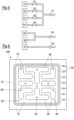
- Figure 6 shows a front view of another gripper 10D (seen from the product 12).
- This has a contact surface 15 which is provided with a sealing device closed in the radial direction, for example with a cutting edge 16.
- a series of irregularly shaped depressions 26 are arranged in the contact surface 15, the base section of which each has at least one suction opening 28.
- the suction openings 28 are connected to one or more pumping devices.
- the depressions 26 thus each form a suction section.
- the suction sections formed in this way are separated by wall sections, the surfaces of which facing the product 12 are part of the contact surface 15.
- the adjacent product 12 thus seals the depressions 26 against one another in the area of the contact surface 15.
- suction openings 28' are also provided in the contact surface 15 at suitable locations (if necessary also radially outside the cutting edge 16).
- the product 12 is not only sucked into the recesses 26, but also (partially) into the aforementioned openings 28, 28'.
- An additional measure to improve the gripping effect of the gripper 10D are inclined tips 30, which mechanically engage the product 12 when the gripper 10D comes into contact with the latter.
- the tips 30 are preferably arranged on the side of the gripper 10D from which a cutting blade penetrates the product 12. The transverse forces that occur in this case additionally press the product 12 into the inclined tips 30.
- Figure 7 shows a gripper 10E, which has a similar structure to the gripper 10B. Instead of the different sized cutting edges 16,16', however, approximately similarly shaped cutting edges 16 are provided. The slopes of the cutting edges 16 of the gripper 10E are arranged less steeply than those of the cutting edges 16, 16' of the gripper 10B. This causes a stronger local compression of the product 12, whereby pores in the product 12 are closed, which can lead to undesirable leakage of air through the product 12. Such leakage flows, which can also occur with unreliable sealing devices, load the pump device(s) of the gripper and/or lead to a poorer fixation of the product.
- the compression effect is further enhanced by an inner flank 16a of the outer cutting edge 16 and an outer flank 16b of the inner cutting edge 16 converging in a direction toward a bottom section of the suction section S2.
- the product 12 is sucked into a cone, whereby it is compressed.
- the flanks 16a, 16b are also provided with suction openings 28" in order to not only compress the product 12 locally, but also to suck it against the flanks 16a, 16b and thus further improve the sealing effect of the cutting edges 16.
- FIG 8 shows a gripper 10F with a suction section S1, the suction chamber 20 of which is sealed from the environment in the radial direction by a sealing lip 24 that lies tightly against the product 12.
- the suction chamber 20 can be evacuated by pumping devices P1, P2.
- a cooling device 32 is provided, with which the gripper 10F can be cooled in sections.
- the cooling device 32 has at least one coolant channel 34 through which a suitable coolant - for example liquid nitrogen, brine, supercooled compressed air - can be passed. This can cause local icing of the product 12 with the gripper 10F, which supports the fixation of the product 12 (in particular on a cutting blade entry side of the product 12).
- any water contained in the product 12 is at least partially sucked out of the product 12 and is available for freezing, with which the product 12 and the gripper 10F are additionally coupled to one another.
- water can also be injected into the suction chamber 20.
- the gripper 10F has an injection opening 36.
- a coolant can also be introduced into the suction chamber 20 through the injection opening 36 in order to cool it. For example, cold nitrogen is first blown into the suction chamber 20 in order to pre-cool it and the product 12. Water is then introduced through the injection opening 36 and at the same time a negative pressure is generated in the suction chamber 20.
- the negative pressure ensures, among other things, an improved distribution of the water in the suction chamber 20, which freezes quickly due to the pre-cooling.
- the freezing thus generated is maintained by the cooling device 32. It is understood that, depending on the properties of the product 12 to be held and due to other requirements, a wide variety of variations in the procedure for producing icing (for example, different coolant-water injection cycles) are conceivable.
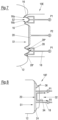
- Figure 9 shows a gripper 10G with three suction sections S1, S2, S3, each of which is delimited in the radial direction by a cutting edge 16.
- the suction sections S2 and S3 are assigned to gripper sections 11A, 11B, which are arranged to be laterally movable. A certain axial mobility is also permitted alternatively or additionally by appropriate devices.
- the mobility of the gripper sections 11A, 11B compensates for vibrations caused by the cutting blade S entering the product 12. This prevents leaks from occurring in the area of the suction sections S2, S3.
- the gripper section 11C is essentially fixed, at least with regard to lateral movements (advancement of the product 12 should of course still be possible).
- the lateral mobility of the sections 11A, 11B can be provided, for example, by articulated and/or elastic components.
- the mobility of the sections 11A, 11B can be specifically changed in order to be able to generate adapted gripper properties in the various phases of gripping and cutting the product 12.
- Figure 10 shows a gripper 10H with several suction sections S1 to S6 in a front view, wherein the suction sections S3 and S6 are arranged on a common gripper section 11C, which, like the gripper section 11C of the gripper 10G, is essentially insensitive to lateral movements.
- the gripper sections 11A, 11B assigned to the suction sections S1, S2, S4, S5 allow lateral movements.
- the example shown is intended to demonstrate that different suction sections can be combined as desired into groups that have different properties with regard to lateral mobility.
- the Figures 11 and 12 show a gripper 10I which has a suction device 14 which can adapt to the surface geometry of the product 12.
- the suction device 14 has a deformable element 38, the side of which facing the product 12 is divided into several suction sections S1 to S5 by beads 22 (of course, other sealing devices can also be used).
- the suction sections S1 to S5 are in turn connected to suitable pumping devices P1 to P5 (it goes without saying that separate pumping devices do not necessarily have to be provided, compare in particular the explanations for Figure 5 ).
- the suction device 14 In order to grip the product 12, the suction device 14 is pressed against the product 12, whereby the deformable element 38 adapts to the geometry of the product 12 (see Figure 12 ). It adheres to the surface, thereby achieving a good seal between the suction sections S1 to S5.
- the deformable element 38 can be elastic. However, it is also possible to ensure that the shape of the suction device 14 is fixed by means of a suitable integration of electro- or magnetorheological components.
- the deformable element 38 can also contain a liquid, for example, which changes its state of aggregation through suitable cooling, whereby the shape obtained by pressing is fixed. Deviating from the embodiment shown, the deformable element 38 can also be provided, for example, only in an edge region of the suction device 14 in order to enable at least partial adaptation of the surface facing the product 12.
- Figure 13 shows a gripper 10H with a suction device 14, the outer edge of which is provided with a sealing lip 24 in order to define a suction space S1.
- the suction device 14 can be partially elastic in order to be able to cling to the surface of the product 12.
- Figure 14 shows a gripper 10J with a suction device 14, which has a suction section S1.
- the suction device 14 rests with its contact surface 15 on the product 12.
- the contact surface 15 is provided with tips 30 to improve the fixation of the product 12.
- the suction section 16 is limited by a cutting edge 16.
- mechanical fixing means in addition to the fixing effect provided by the suction device 14.
- these are selectively pivotable claws 40. They engage in the product 12 in the area of the suction section S1.
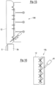
- Figure 15 shows a gripper 10K, which has a hook 42 on its side facing the cutting blade S that can be inserted obliquely into the product 12. Due to the transverse forces that occur during cutting, which have already been discussed several times above, the product 12 is pressed into the hook 42, which improves the fixation of the product 12 to the gripper 10K.
- the hook 42 can can also be designed as a tip or spike.
- a plurality of such elements 42 are provided, which are arranged, for example, in a row (such as the tips 30 in Figure 6 ).
- Figure 16 shows a gripper 10L, which has a plurality of elements 42, which alternately engage obliquely in the product 12 in order to achieve a particularly good fixation of the product 12.
- a pneumatic cylinder 44 can be provided to actuate the elements 42.
- Alternative activation mechanisms electrical, hydraulic, mechanical, Certainly are also conceivable.
- the design or process-related measures described above to improve the sealing of the suction device 14 can be combined as desired to create the gripper or an optimized gripping/cutting process that is suitable for the respective requirement. It is therefore entirely possible to combine the concept of several independent suction sections with additional fixing measures (elements that can be mechanically brought into engagement with the product, (local) icing, etc.). A laterally movable arrangement of the gripper or individual sections of the gripper can also be easily integrated into the described embodiments. Particular attention is paid to the cutting blade entry side of the product to be cut, since this is where the greatest transverse forces occur.
- the gripper When designing the gripper according to the invention, particular emphasis is placed on a hygienic design and good cleaning ability. Parts of the gripper, in particular the suction device and its components, are designed to be easily removable. This also facilitates visual inspection of the essential components of the gripper, especially on the suction side.
Landscapes
- Engineering & Computer Science (AREA)
- Mechanical Engineering (AREA)
- Life Sciences & Earth Sciences (AREA)
- Forests & Forestry (AREA)
- Robotics (AREA)
- Food Science & Technology (AREA)
- Manipulator (AREA)
- Auxiliary Devices For And Details Of Packaging Control (AREA)
Applications Claiming Priority (2)
| Application Number | Priority Date | Filing Date | Title |
|---|---|---|---|
| DE102017102385.2A DE102017102385A1 (de) | 2017-02-07 | 2017-02-07 | Greifer, Schneidvorrichtung und Verfahren zum Schneiden eines Produkts |
| EP18154048.5A EP3366438B1 (de) | 2017-02-07 | 2018-01-30 | Greifer, schneidvorrichtung und verfahren zum schneiden eines produkts |
Related Parent Applications (2)
| Application Number | Title | Priority Date | Filing Date |
|---|---|---|---|
| EP18154048.5A Division-Into EP3366438B1 (de) | 2017-02-07 | 2018-01-30 | Greifer, schneidvorrichtung und verfahren zum schneiden eines produkts |
| EP18154048.5A Division EP3366438B1 (de) | 2017-02-07 | 2018-01-30 | Greifer, schneidvorrichtung und verfahren zum schneiden eines produkts |
Publications (2)
| Publication Number | Publication Date |
|---|---|
| EP3851260A1 EP3851260A1 (de) | 2021-07-21 |
| EP3851260B1 true EP3851260B1 (de) | 2024-08-07 |
Family
ID=61132018
Family Applications (2)
| Application Number | Title | Priority Date | Filing Date |
|---|---|---|---|
| EP21159074.0A Active EP3851260B1 (de) | 2017-02-07 | 2018-01-30 | Greifer für schneidvorrichtung |
| EP18154048.5A Active EP3366438B1 (de) | 2017-02-07 | 2018-01-30 | Greifer, schneidvorrichtung und verfahren zum schneiden eines produkts |
Family Applications After (1)
| Application Number | Title | Priority Date | Filing Date |
|---|---|---|---|
| EP18154048.5A Active EP3366438B1 (de) | 2017-02-07 | 2018-01-30 | Greifer, schneidvorrichtung und verfahren zum schneiden eines produkts |
Country Status (4)
| Country | Link |
|---|---|
| US (1) | US11207792B2 (pl) |
| EP (2) | EP3851260B1 (pl) |
| DE (1) | DE102017102385A1 (pl) |
| PL (2) | PL3851260T3 (pl) |
Families Citing this family (9)
| Publication number | Priority date | Publication date | Assignee | Title |
|---|---|---|---|---|
| US11059197B2 (en) | 2017-08-24 | 2021-07-13 | Cozzini Llc | Method of slicing a food item and slicing mechanism employing a gripping element that generates a vacuum grip |
| DE102017126377A1 (de) * | 2017-11-10 | 2019-05-16 | Weber Maschinenbau Gmbh Breidenbach | Greifer |
| CN110539353A (zh) * | 2019-10-16 | 2019-12-06 | 利辛县富亚纱网有限公司 | 一种纱网包边夹具 |
| JP7376336B2 (ja) * | 2019-12-11 | 2023-11-08 | 株式会社京都製作所 | 包装体開封システム |
| DE202021002529U1 (de) | 2021-07-29 | 2021-09-28 | Vulkan Technic Gmbh | Vorrichtung zum Schneiden von Schnittfiguren insbesondere Klebepads aus bandförmigem Material mittels Schneideinrichtung und einem variablen Greifersystem zur Aufnahme der ausgeschnittenen Klebepads |
| DE102023101301B3 (de) | 2023-01-19 | 2024-03-14 | Harburg-Freudenberger Maschinenbau Gmbh | Vakuumheber zum Heben einer Materialeinheit und Verfahren zum Betrieb eines Vakuumhebers |
| DE102023108709A1 (de) * | 2023-04-05 | 2024-10-10 | Multivac Sepp Haggenmüller Se & Co. Kg | Aufschneide-Maschine mit Parkposition für Greifer |
| DE102023116735B4 (de) * | 2023-06-26 | 2025-06-05 | Harburg-Freudenberger Maschinenbau Gmbh | Verfahren zum Heben einer Materialeinheit aus einer Materialanordnung |
| CN121084883B (zh) * | 2025-11-10 | 2026-03-10 | 长春正海汽车内饰件有限公司 | 一种汽车nappa真皮顶棚包覆设备及其制作方法 |
Family Cites Families (47)
| Publication number | Priority date | Publication date | Assignee | Title |
|---|---|---|---|---|
| US2487271A (en) * | 1946-10-09 | 1949-11-08 | Clarence R Petri | Doughnut machine |
| US2895739A (en) | 1956-02-13 | 1959-07-21 | Owens Illinois Glass Co | Vacuum chucks |
| FR1521022A (fr) | 1966-06-01 | 1968-04-12 | Budd Co | Dispositif de levage à ventouse |
| US3361469A (en) | 1966-06-01 | 1968-01-02 | Budd Co | Fluid pressure controlled holding device for a lift unit |
| US3797343A (en) | 1971-05-24 | 1974-03-19 | Kraftco Corp | Rapid slicing machine |
| FR2224375A1 (en) | 1973-04-09 | 1974-10-31 | Unelec | Moving pavement for pedestrian transport - consists of a metal endless belt driven by a powered roller |
| US3880295A (en) | 1973-11-08 | 1975-04-29 | Thermoplastic Engineering Inc | Vacuum gripper device for slicing machine |
| US4014494A (en) | 1974-07-05 | 1977-03-29 | Nikolai Alexeevich Glagolev | Cold butt-welding machine |
| GB1498281A (en) | 1975-04-09 | 1978-01-18 | British Hydromechanics | Slotted worktable |
| GB1560657A (en) | 1976-10-14 | 1980-02-06 | Ealing Beck Ltd | Suction mounting |
| DE3010732A1 (de) | 1980-03-20 | 1981-10-01 | Dipl.-Ing. Schindler & Wagner KG, 7067 Plüderhausen | Automatische spannzange und automatische produktzufuehrung unter verwendung einer solchen fuer eine schneidmaschine |
| US4428263A (en) | 1981-10-08 | 1984-01-31 | Formax, Inc. | Food loaf slicing machine |
| GB2205558A (en) | 1987-05-18 | 1988-12-14 | Lonhro Plc | Recovery of alumina from aluminosilicates |
| DE4212095C1 (pl) * | 1992-04-10 | 1993-08-19 | Man Roland Druckmaschinen Ag, 6050 Offenbach, De | |
| US5660380A (en) * | 1995-08-15 | 1997-08-26 | W. L. Gore & Associates, Inc. | Vacuum fixture and method for dimensioning and manipulating materials |
| DE19735597A1 (de) | 1997-08-15 | 1999-02-25 | Schill Maja Masch | Vorrichtung zum Portionieren eines Fleischstücks |
| DE19806561C2 (de) | 1998-02-17 | 2000-04-27 | Thomas Voelkl | Kalibrierschneidvorrichtung |
| DE19908931B4 (de) | 1998-03-05 | 2004-12-09 | Dr.Wolf & Partner Ingenieurbüro Für Lebensmitteltechnik Gmbh | Verfahren und Vorrichtung zum Bearbeiten von Fisch |
| DE10024913A1 (de) | 2000-05-19 | 2001-11-29 | Schindler & Wagner Gmbh & Co | Schneidmaschine für laibförmige Produkte |
| GB2364894B8 (en) | 2000-07-19 | 2010-07-07 | Fmc Corp | Three axis portioning method |
| DE10124118B4 (de) | 2001-05-17 | 2004-04-29 | Thomas Völkl | Kalibrierschneidvorrichtung |
| EP2420824B1 (en) * | 2001-06-29 | 2018-11-28 | Meso Scale Technologies LLC | Multi-well plate having an array of wells and kit for use in the conduct of an ECL assay |
| GB0116976D0 (en) | 2001-07-12 | 2001-09-05 | Apple Engineering Ltd | Food processing apparatus |
| ITRE20020070A1 (it) | 2002-09-19 | 2004-03-20 | Gianbon Srl | Dispositivo di presa per prodotti da affettare automaticamente. |
| DE10304773A1 (de) | 2003-02-05 | 2004-08-19 | Maja-Maschinenfabrik Hermann Schill Gmbh & Co. Kg | Vorrichtung und Verfahren zum Portionieren eines Lebensmittelstücks |
| US20050034576A1 (en) | 2003-08-11 | 2005-02-17 | Ray Theodore M. | Bun slicer |
| US7493841B1 (en) * | 2005-01-19 | 2009-02-24 | Kaplan Robert E | Slicer |
| DE102005010184A1 (de) | 2005-03-02 | 2006-09-07 | Cfs Kempten Gmbh | Greifer mit Anlageflächen |
| US7175446B2 (en) | 2005-03-28 | 2007-02-13 | Tyco Electronics Corporation | Electrical connector |
| DE102007058114A1 (de) * | 2007-12-04 | 2009-06-10 | Festo Ag & Co. Kg | Vakuumerzeugervorrichtung und Verfahren zu ihrem Betreiben |
| DE102008011980B3 (de) | 2008-02-29 | 2009-07-16 | Reifenhäuser, Uwe | Verfahren zum Schneiden eines strangförmigen Lebensmittels sowie Schneidmaschine |
| DE102008011985B3 (de) | 2008-02-29 | 2009-07-02 | Reifenhäuser, Uwe | Verfahren zum Schneiden eines strangförmigen Lebensmittels sowie Schneidmaschine |
| DE102008011979B9 (de) | 2008-02-29 | 2010-01-28 | Reifenhäuser, Uwe | Verfahren zum Schneiden eines strangförmigen Lebensmittels sowie Schneidmaschine |
| FR2929257B1 (fr) | 2008-03-28 | 2010-04-23 | Ballina Freres De | Prehenseur pneumatique et dispositif de prehension comportant une pluralite de tels prehenseurs |
| DE202008010424U1 (de) | 2008-07-30 | 2009-12-24 | J. Schmalz Gmbh | Mit Druckluft betriebener Flächensauggreifer |
| DE102010038931B4 (de) | 2010-08-04 | 2013-11-28 | Deutsches Institut Für Lebensmitteltechnik E.V. | Sauggreifer für Lebensmittel |
| DE102011012880B4 (de) * | 2010-10-01 | 2014-03-20 | CFS Bühl GmbH | Hochleistungsschneidemaschine mit einem Greifer |
| DE102011083498B4 (de) | 2011-09-27 | 2014-08-21 | Uwe Reifenhäuser | Sauggreifer und Verfahren zum Reinigen eines Sauggreifers |
| FR2997031B1 (fr) * | 2012-10-23 | 2016-07-01 | Bel Fromageries | Dispositif de prehension d'au moins un produit deformable. |
| DE102013215725A1 (de) * | 2013-08-08 | 2015-02-12 | Deutsches Institut Für Lebensmitteltechnik E.V. | Haltevorrichtung |
| EP2837289A1 (de) | 2013-08-15 | 2015-02-18 | A O Ideas GmbH | Verfahren und Vorrichtung zur Zubereitung einer Käsespeise und Käsespeise |
| DE102014101626A1 (de) | 2014-02-10 | 2015-08-13 | Weber Maschinenbau Gmbh Breidenbach | Verbinden von Lebensmittelprodukten |
| DE102014215102A1 (de) | 2014-07-31 | 2016-02-04 | J. Schmalz Gmbh | Flächensauggreifer |
| EP3224005B1 (de) | 2014-11-25 | 2019-08-07 | GEA Food Solutions Germany GmbH | Hochleistungsslicer mit stoffschlüssigem greifer |
| JP2020529929A (ja) * | 2017-08-03 | 2020-10-15 | ソフト ロボティクス, インコーポレイテッド | 肉製品を取り扱うためのロボットグリッパ |
| US11059197B2 (en) * | 2017-08-24 | 2021-07-13 | Cozzini Llc | Method of slicing a food item and slicing mechanism employing a gripping element that generates a vacuum grip |
| DE102017126377A1 (de) * | 2017-11-10 | 2019-05-16 | Weber Maschinenbau Gmbh Breidenbach | Greifer |
-
2017
- 2017-02-07 DE DE102017102385.2A patent/DE102017102385A1/de not_active Withdrawn
-
2018
- 2018-01-30 EP EP21159074.0A patent/EP3851260B1/de active Active
- 2018-01-30 PL PL21159074.0T patent/PL3851260T3/pl unknown
- 2018-01-30 PL PL18154048T patent/PL3366438T3/pl unknown
- 2018-01-30 EP EP18154048.5A patent/EP3366438B1/de active Active
- 2018-02-01 US US15/886,542 patent/US11207792B2/en active Active
Also Published As
| Publication number | Publication date |
|---|---|
| PL3851260T3 (pl) | 2024-12-30 |
| EP3366438B1 (de) | 2021-04-28 |
| PL3366438T3 (pl) | 2021-11-22 |
| DE102017102385A1 (de) | 2018-08-09 |
| EP3366438A1 (de) | 2018-08-29 |
| US20180222074A1 (en) | 2018-08-09 |
| EP3851260A1 (de) | 2021-07-21 |
| US11207792B2 (en) | 2021-12-28 |
Similar Documents
| Publication | Publication Date | Title |
|---|---|---|
| EP3366438B1 (de) | Greifer, schneidvorrichtung und verfahren zum schneiden eines produkts | |
| EP0115783B1 (de) | Messerzylinder zum Bearbeiten von bahnförmigem Gut | |
| EP1598276B1 (de) | Verpackungsmaschine und Verfahren zum Schneiden von Packungen | |
| DE29905951U1 (de) | Sauggreifer | |
| DE102008011980B3 (de) | Verfahren zum Schneiden eines strangförmigen Lebensmittels sowie Schneidmaschine | |
| DE102017126377A1 (de) | Greifer | |
| DE202011101706U1 (de) | Werkzeughalter | |
| DE102021203789B3 (de) | Stanzwerkzeug | |
| DE102008011979B9 (de) | Verfahren zum Schneiden eines strangförmigen Lebensmittels sowie Schneidmaschine | |
| EP2489484A1 (de) | Verfahren zur Montage eines Messers an einem Zylinderkörper, Messer, Zylinderkörper sowie Schneideinrichtung | |
| DE102017123162B4 (de) | Ring-Montagevorrichtung sowie Verfahren zur Montage eines Rings | |
| DE102015205221A1 (de) | Tiefziehverpackungsmaschine, Verfahren und Verpackung | |
| EP3491663A1 (de) | Vorrichtung zum greifen und transportieren von substraten | |
| EP3548234B1 (de) | Mehrteiliges langmesser | |
| AT501246A1 (de) | Querschneidvorrichtung und -verfahren für bahnmaterial | |
| EP2711116A1 (de) | Druckbalken für eine Sägevorrichtung | |
| DE102005047646B4 (de) | Vorrichtung zum Ausstanzen von Zuschnitten aus bahnförmigem Material | |
| DE102011085113A1 (de) | Trocknung von Trocknungsgut unter Verwendung von Trocknungsluft | |
| EP2644517B1 (de) | Mehrreihige Siegelstation, entsprechende Verpackungsmaschine und entsprechendes Verfahren | |
| EP2105270B1 (de) | Zuführeinrichtung für eine Bearbeitungsmaschine | |
| DE102008020295A1 (de) | Vorrichtung zum Transport von Folie | |
| DE202010016582U1 (de) | Schneidlinie | |
| WO2015128025A1 (de) | Vorrichtung zum automatischen schneiden und abführen einer materialbahn sowie verfahren hierzu | |
| DE19948955B4 (de) | Bahnschneidvorrichtung mit einer integrierten Messeranordnung in einer Rollenrotationsdruckmaschine | |
| AT12250U1 (de) | Gelenkdichtung für spritzgiessmaschinen |
Legal Events
| Date | Code | Title | Description |
|---|---|---|---|
| PUAI | Public reference made under article 153(3) epc to a published international application that has entered the european phase |
Free format text: ORIGINAL CODE: 0009012 |
|
| STAA | Information on the status of an ep patent application or granted ep patent |
Free format text: STATUS: THE APPLICATION HAS BEEN PUBLISHED |
|
| AC | Divisional application: reference to earlier application |
Ref document number: 3366438 Country of ref document: EP Kind code of ref document: P |
|
| AK | Designated contracting states |
Kind code of ref document: A1 Designated state(s): AL AT BE BG CH CY CZ DE DK EE ES FI FR GB GR HR HU IE IS IT LI LT LU LV MC MK MT NL NO PL PT RO RS SE SI SK SM TR |
|
| STAA | Information on the status of an ep patent application or granted ep patent |
Free format text: STATUS: REQUEST FOR EXAMINATION WAS MADE |
|
| 17P | Request for examination filed |
Effective date: 20220114 |
|
| RBV | Designated contracting states (corrected) |
Designated state(s): AL AT BE BG CH CY CZ DE DK EE ES FI FR GB GR HR HU IE IS IT LI LT LU LV MC MK MT NL NO PL PT RO RS SE SI SK SM TR |
|
| P01 | Opt-out of the competence of the unified patent court (upc) registered |
Effective date: 20230522 |
|
| RAP3 | Party data changed (applicant data changed or rights of an application transferred) |
Owner name: WEBER FOOD TECHNOLOGY GMBH |
|
| RIC1 | Information provided on ipc code assigned before grant |
Ipc: B26D 7/01 20060101ALN20240304BHEP Ipc: B25J 11/00 20060101ALI20240304BHEP Ipc: B25J 15/06 20060101ALI20240304BHEP Ipc: A47J 43/18 20060101ALI20240304BHEP Ipc: B26D 7/06 20060101AFI20240304BHEP |
|
| GRAP | Despatch of communication of intention to grant a patent |
Free format text: ORIGINAL CODE: EPIDOSNIGR1 |
|
| STAA | Information on the status of an ep patent application or granted ep patent |
Free format text: STATUS: GRANT OF PATENT IS INTENDED |
|
| INTG | Intention to grant announced |
Effective date: 20240419 |
|
| RIC1 | Information provided on ipc code assigned before grant |
Ipc: B26D 7/01 20060101ALN20240405BHEP Ipc: B25J 11/00 20060101ALI20240405BHEP Ipc: B25J 15/06 20060101ALI20240405BHEP Ipc: A47J 43/18 20060101ALI20240405BHEP Ipc: B26D 7/06 20060101AFI20240405BHEP |
|
| GRAS | Grant fee paid |
Free format text: ORIGINAL CODE: EPIDOSNIGR3 |
|
| GRAA | (expected) grant |
Free format text: ORIGINAL CODE: 0009210 |
|
| STAA | Information on the status of an ep patent application or granted ep patent |
Free format text: STATUS: THE PATENT HAS BEEN GRANTED |
|
| AC | Divisional application: reference to earlier application |
Ref document number: 3366438 Country of ref document: EP Kind code of ref document: P |
|
| AK | Designated contracting states |
Kind code of ref document: B1 Designated state(s): AL AT BE BG CH CY CZ DE DK EE ES FI FR GB GR HR HU IE IS IT LI LT LU LV MC MK MT NL NO PL PT RO RS SE SI SK SM TR |
|
| REG | Reference to a national code |
Ref country code: GB Ref legal event code: FG4D Free format text: NOT ENGLISH |
|
| REG | Reference to a national code |
Ref country code: CH Ref legal event code: EP |
|
| REG | Reference to a national code |
Ref country code: NL Ref legal event code: FP Ref country code: IE Ref legal event code: FG4D Free format text: LANGUAGE OF EP DOCUMENT: GERMAN |
|
| REG | Reference to a national code |
Ref country code: DE Ref legal event code: R096 Ref document number: 502018015001 Country of ref document: DE |
|
| REG | Reference to a national code |
Ref country code: LT Ref legal event code: MG9D |
|
| PG25 | Lapsed in a contracting state [announced via postgrant information from national office to epo] |
Ref country code: NO Free format text: LAPSE BECAUSE OF FAILURE TO SUBMIT A TRANSLATION OF THE DESCRIPTION OR TO PAY THE FEE WITHIN THE PRESCRIBED TIME-LIMIT Effective date: 20241107 |
|
| PG25 | Lapsed in a contracting state [announced via postgrant information from national office to epo] |
Ref country code: GR Free format text: LAPSE BECAUSE OF FAILURE TO SUBMIT A TRANSLATION OF THE DESCRIPTION OR TO PAY THE FEE WITHIN THE PRESCRIBED TIME-LIMIT Effective date: 20241108 Ref country code: PT Free format text: LAPSE BECAUSE OF FAILURE TO SUBMIT A TRANSLATION OF THE DESCRIPTION OR TO PAY THE FEE WITHIN THE PRESCRIBED TIME-LIMIT Effective date: 20241209 Ref country code: FI Free format text: LAPSE BECAUSE OF FAILURE TO SUBMIT A TRANSLATION OF THE DESCRIPTION OR TO PAY THE FEE WITHIN THE PRESCRIBED TIME-LIMIT Effective date: 20240807 |
|
| PG25 | Lapsed in a contracting state [announced via postgrant information from national office to epo] |
Ref country code: BG Free format text: LAPSE BECAUSE OF FAILURE TO SUBMIT A TRANSLATION OF THE DESCRIPTION OR TO PAY THE FEE WITHIN THE PRESCRIBED TIME-LIMIT Effective date: 20240807 |
|
| PG25 | Lapsed in a contracting state [announced via postgrant information from national office to epo] |
Ref country code: LV Free format text: LAPSE BECAUSE OF FAILURE TO SUBMIT A TRANSLATION OF THE DESCRIPTION OR TO PAY THE FEE WITHIN THE PRESCRIBED TIME-LIMIT Effective date: 20240807 |
|
| PG25 | Lapsed in a contracting state [announced via postgrant information from national office to epo] |
Ref country code: IS Free format text: LAPSE BECAUSE OF FAILURE TO SUBMIT A TRANSLATION OF THE DESCRIPTION OR TO PAY THE FEE WITHIN THE PRESCRIBED TIME-LIMIT Effective date: 20241207 |
|
| PG25 | Lapsed in a contracting state [announced via postgrant information from national office to epo] |
Ref country code: HR Free format text: LAPSE BECAUSE OF FAILURE TO SUBMIT A TRANSLATION OF THE DESCRIPTION OR TO PAY THE FEE WITHIN THE PRESCRIBED TIME-LIMIT Effective date: 20240807 |
|
| PG25 | Lapsed in a contracting state [announced via postgrant information from national office to epo] |
Ref country code: RS Free format text: LAPSE BECAUSE OF FAILURE TO SUBMIT A TRANSLATION OF THE DESCRIPTION OR TO PAY THE FEE WITHIN THE PRESCRIBED TIME-LIMIT Effective date: 20241107 Ref country code: ES Free format text: LAPSE BECAUSE OF FAILURE TO SUBMIT A TRANSLATION OF THE DESCRIPTION OR TO PAY THE FEE WITHIN THE PRESCRIBED TIME-LIMIT Effective date: 20240807 |
|
| PG25 | Lapsed in a contracting state [announced via postgrant information from national office to epo] |
Ref country code: RS Free format text: LAPSE BECAUSE OF FAILURE TO SUBMIT A TRANSLATION OF THE DESCRIPTION OR TO PAY THE FEE WITHIN THE PRESCRIBED TIME-LIMIT Effective date: 20241107 Ref country code: PT Free format text: LAPSE BECAUSE OF FAILURE TO SUBMIT A TRANSLATION OF THE DESCRIPTION OR TO PAY THE FEE WITHIN THE PRESCRIBED TIME-LIMIT Effective date: 20241209 Ref country code: NO Free format text: LAPSE BECAUSE OF FAILURE TO SUBMIT A TRANSLATION OF THE DESCRIPTION OR TO PAY THE FEE WITHIN THE PRESCRIBED TIME-LIMIT Effective date: 20241107 Ref country code: LV Free format text: LAPSE BECAUSE OF FAILURE TO SUBMIT A TRANSLATION OF THE DESCRIPTION OR TO PAY THE FEE WITHIN THE PRESCRIBED TIME-LIMIT Effective date: 20240807 Ref country code: IS Free format text: LAPSE BECAUSE OF FAILURE TO SUBMIT A TRANSLATION OF THE DESCRIPTION OR TO PAY THE FEE WITHIN THE PRESCRIBED TIME-LIMIT Effective date: 20241207 Ref country code: HR Free format text: LAPSE BECAUSE OF FAILURE TO SUBMIT A TRANSLATION OF THE DESCRIPTION OR TO PAY THE FEE WITHIN THE PRESCRIBED TIME-LIMIT Effective date: 20240807 Ref country code: GR Free format text: LAPSE BECAUSE OF FAILURE TO SUBMIT A TRANSLATION OF THE DESCRIPTION OR TO PAY THE FEE WITHIN THE PRESCRIBED TIME-LIMIT Effective date: 20241108 Ref country code: FI Free format text: LAPSE BECAUSE OF FAILURE TO SUBMIT A TRANSLATION OF THE DESCRIPTION OR TO PAY THE FEE WITHIN THE PRESCRIBED TIME-LIMIT Effective date: 20240807 Ref country code: ES Free format text: LAPSE BECAUSE OF FAILURE TO SUBMIT A TRANSLATION OF THE DESCRIPTION OR TO PAY THE FEE WITHIN THE PRESCRIBED TIME-LIMIT Effective date: 20240807 Ref country code: BG Free format text: LAPSE BECAUSE OF FAILURE TO SUBMIT A TRANSLATION OF THE DESCRIPTION OR TO PAY THE FEE WITHIN THE PRESCRIBED TIME-LIMIT Effective date: 20240807 |
|
| REG | Reference to a national code |
Ref country code: DE Ref legal event code: R081 Ref document number: 502018015001 Country of ref document: DE Owner name: WEBER FOOD TECHNOLOGY SE & CO. KG, DE Free format text: FORMER OWNER: WEBER FOOD TECHNOLOGY GMBH, 35236 BREIDENBACH, DE |
|
| REG | Reference to a national code |
Ref country code: NL Ref legal event code: PD Owner name: WEBER FOOD TECHNOLOGY SE & CO. KG; DE Free format text: DETAILS ASSIGNMENT: CHANGE OF OWNER(S), CHANGE OF LEGAL ENTITY; FORMER OWNER NAME: WEBER FOOD TECHNOLOGY GMBH Effective date: 20250210 |
|
| REG | Reference to a national code |
Ref country code: GB Ref legal event code: 732E Free format text: REGISTERED BETWEEN 20250206 AND 20250212 |
|
| RAP2 | Party data changed (patent owner data changed or rights of a patent transferred) |
Owner name: WEBER FOOD TECHNOLOGY SE & CO. KG |
|
| PG25 | Lapsed in a contracting state [announced via postgrant information from national office to epo] |
Ref country code: DK Free format text: LAPSE BECAUSE OF FAILURE TO SUBMIT A TRANSLATION OF THE DESCRIPTION OR TO PAY THE FEE WITHIN THE PRESCRIBED TIME-LIMIT Effective date: 20240807 Ref country code: SM Free format text: LAPSE BECAUSE OF FAILURE TO SUBMIT A TRANSLATION OF THE DESCRIPTION OR TO PAY THE FEE WITHIN THE PRESCRIBED TIME-LIMIT Effective date: 20240807 |
|
| PG25 | Lapsed in a contracting state [announced via postgrant information from national office to epo] |
Ref country code: EE Free format text: LAPSE BECAUSE OF FAILURE TO SUBMIT A TRANSLATION OF THE DESCRIPTION OR TO PAY THE FEE WITHIN THE PRESCRIBED TIME-LIMIT Effective date: 20240807 |
|
| PG25 | Lapsed in a contracting state [announced via postgrant information from national office to epo] |
Ref country code: CZ Free format text: LAPSE BECAUSE OF FAILURE TO SUBMIT A TRANSLATION OF THE DESCRIPTION OR TO PAY THE FEE WITHIN THE PRESCRIBED TIME-LIMIT Effective date: 20240807 |
|
| PG25 | Lapsed in a contracting state [announced via postgrant information from national office to epo] |
Ref country code: SK Free format text: LAPSE BECAUSE OF FAILURE TO SUBMIT A TRANSLATION OF THE DESCRIPTION OR TO PAY THE FEE WITHIN THE PRESCRIBED TIME-LIMIT Effective date: 20240807 |
|
| REG | Reference to a national code |
Ref country code: DE Ref legal event code: R097 Ref document number: 502018015001 Country of ref document: DE |
|
| PLBE | No opposition filed within time limit |
Free format text: ORIGINAL CODE: 0009261 |
|
| STAA | Information on the status of an ep patent application or granted ep patent |
Free format text: STATUS: NO OPPOSITION FILED WITHIN TIME LIMIT |
|
| 26N | No opposition filed |
Effective date: 20250508 |
|
| REG | Reference to a national code |
Ref country code: CH Ref legal event code: PL |
|
| PG25 | Lapsed in a contracting state [announced via postgrant information from national office to epo] |
Ref country code: SE Free format text: LAPSE BECAUSE OF FAILURE TO SUBMIT A TRANSLATION OF THE DESCRIPTION OR TO PAY THE FEE WITHIN THE PRESCRIBED TIME-LIMIT Effective date: 20240807 |
|
| PG25 | Lapsed in a contracting state [announced via postgrant information from national office to epo] |
Ref country code: LU Free format text: LAPSE BECAUSE OF NON-PAYMENT OF DUE FEES Effective date: 20250130 Ref country code: MC Free format text: LAPSE BECAUSE OF FAILURE TO SUBMIT A TRANSLATION OF THE DESCRIPTION OR TO PAY THE FEE WITHIN THE PRESCRIBED TIME-LIMIT Effective date: 20240807 |
|
| PG25 | Lapsed in a contracting state [announced via postgrant information from national office to epo] |
Ref country code: BE Free format text: LAPSE BECAUSE OF NON-PAYMENT OF DUE FEES Effective date: 20250131 |
|
| PG25 | Lapsed in a contracting state [announced via postgrant information from national office to epo] |
Ref country code: CH Free format text: LAPSE BECAUSE OF NON-PAYMENT OF DUE FEES Effective date: 20250131 |
|
| REG | Reference to a national code |
Ref country code: BE Ref legal event code: MM Effective date: 20250131 |
|
| PG25 | Lapsed in a contracting state [announced via postgrant information from national office to epo] |
Ref country code: IE Free format text: LAPSE BECAUSE OF NON-PAYMENT OF DUE FEES Effective date: 20250130 |
|
| PG25 | Lapsed in a contracting state [announced via postgrant information from national office to epo] |
Ref country code: IT Free format text: LAPSE BECAUSE OF FAILURE TO SUBMIT A TRANSLATION OF THE DESCRIPTION OR TO PAY THE FEE WITHIN THE PRESCRIBED TIME-LIMIT Effective date: 20240807 |
|
| PGFP | Annual fee paid to national office [announced via postgrant information from national office to epo] |
Ref country code: NL Payment date: 20260121 Year of fee payment: 9 |
|
| REG | Reference to a national code |
Ref country code: AT Ref legal event code: MM01 Ref document number: 1710444 Country of ref document: AT Kind code of ref document: T Effective date: 20250130 |
|
| PGFP | Annual fee paid to national office [announced via postgrant information from national office to epo] |
Ref country code: GB Payment date: 20260122 Year of fee payment: 9 |
|
| PGFP | Annual fee paid to national office [announced via postgrant information from national office to epo] |
Ref country code: DE Payment date: 20260120 Year of fee payment: 9 |
|
| PG25 | Lapsed in a contracting state [announced via postgrant information from national office to epo] |
Ref country code: AT Free format text: LAPSE BECAUSE OF NON-PAYMENT OF DUE FEES Effective date: 20250130 |
|
| PG25 | Lapsed in a contracting state [announced via postgrant information from national office to epo] |
Ref country code: RO Free format text: LAPSE BECAUSE OF FAILURE TO SUBMIT A TRANSLATION OF THE DESCRIPTION OR TO PAY THE FEE WITHIN THE PRESCRIBED TIME-LIMIT Effective date: 20240807 |
|
| PGFP | Annual fee paid to national office [announced via postgrant information from national office to epo] |
Ref country code: FR Payment date: 20260128 Year of fee payment: 9 |
|
| PGFP | Annual fee paid to national office [announced via postgrant information from national office to epo] |
Ref country code: PL Payment date: 20260116 Year of fee payment: 9 |