EP3851268B1 - Identifizierung von 3d-gedruckten objekten - Google Patents
Identifizierung von 3d-gedruckten objekten Download PDFInfo
- Publication number
- EP3851268B1 EP3851268B1 EP20290007.2A EP20290007A EP3851268B1 EP 3851268 B1 EP3851268 B1 EP 3851268B1 EP 20290007 A EP20290007 A EP 20290007A EP 3851268 B1 EP3851268 B1 EP 3851268B1
- Authority
- EP
- European Patent Office
- Prior art keywords
- secondary structure
- printed
- representation
- image
- objects
- Prior art date
- Legal status (The legal status is an assumption and is not a legal conclusion. Google has not performed a legal analysis and makes no representation as to the accuracy of the status listed.)
- Active
Links
Images


Classifications
-
- B—PERFORMING OPERATIONS; TRANSPORTING
- B29—WORKING OF PLASTICS; WORKING OF SUBSTANCES IN A PLASTIC STATE IN GENERAL
- B29C—SHAPING OR JOINING OF PLASTICS; SHAPING OF MATERIAL IN A PLASTIC STATE, NOT OTHERWISE PROVIDED FOR; AFTER-TREATMENT OF THE SHAPED PRODUCTS, e.g. REPAIRING
- B29C64/00—Additive manufacturing, i.e. manufacturing of three-dimensional [3D] objects by additive deposition, additive agglomeration or additive layering, e.g. by 3D printing, stereolithography or selective laser sintering
- B29C64/40—Structures for supporting 3D objects during manufacture and intended to be sacrificed after completion thereof
-
- B—PERFORMING OPERATIONS; TRANSPORTING
- B29—WORKING OF PLASTICS; WORKING OF SUBSTANCES IN A PLASTIC STATE IN GENERAL
- B29C—SHAPING OR JOINING OF PLASTICS; SHAPING OF MATERIAL IN A PLASTIC STATE, NOT OTHERWISE PROVIDED FOR; AFTER-TREATMENT OF THE SHAPED PRODUCTS, e.g. REPAIRING
- B29C64/00—Additive manufacturing, i.e. manufacturing of three-dimensional [3D] objects by additive deposition, additive agglomeration or additive layering, e.g. by 3D printing, stereolithography or selective laser sintering
- B29C64/30—Auxiliary operations or equipment
- B29C64/386—Data acquisition or data processing for additive manufacturing
-
- B—PERFORMING OPERATIONS; TRANSPORTING
- B33—ADDITIVE MANUFACTURING TECHNOLOGY
- B33Y—ADDITIVE MANUFACTURING, i.e. MANUFACTURING OF THREE-DIMENSIONAL [3D] OBJECTS BY ADDITIVE DEPOSITION, ADDITIVE AGGLOMERATION OR ADDITIVE LAYERING, e.g. BY 3D PRINTING, STEREOLITHOGRAPHY OR SELECTIVE LASER SINTERING
- B33Y10/00—Processes of additive manufacturing
-
- B—PERFORMING OPERATIONS; TRANSPORTING
- B33—ADDITIVE MANUFACTURING TECHNOLOGY
- B33Y—ADDITIVE MANUFACTURING, i.e. MANUFACTURING OF THREE-DIMENSIONAL [3D] OBJECTS BY ADDITIVE DEPOSITION, ADDITIVE AGGLOMERATION OR ADDITIVE LAYERING, e.g. BY 3D PRINTING, STEREOLITHOGRAPHY OR SELECTIVE LASER SINTERING
- B33Y40/00—Auxiliary operations or equipment, e.g. for material handling
- B33Y40/20—Post-treatment, e.g. curing, coating or polishing
-
- B—PERFORMING OPERATIONS; TRANSPORTING
- B33—ADDITIVE MANUFACTURING TECHNOLOGY
- B33Y—ADDITIVE MANUFACTURING, i.e. MANUFACTURING OF THREE-DIMENSIONAL [3D] OBJECTS BY ADDITIVE DEPOSITION, ADDITIVE AGGLOMERATION OR ADDITIVE LAYERING, e.g. BY 3D PRINTING, STEREOLITHOGRAPHY OR SELECTIVE LASER SINTERING
- B33Y50/00—Data acquisition or data processing for additive manufacturing
-
- B—PERFORMING OPERATIONS; TRANSPORTING
- B33—ADDITIVE MANUFACTURING TECHNOLOGY
- B33Y—ADDITIVE MANUFACTURING, i.e. MANUFACTURING OF THREE-DIMENSIONAL [3D] OBJECTS BY ADDITIVE DEPOSITION, ADDITIVE AGGLOMERATION OR ADDITIVE LAYERING, e.g. BY 3D PRINTING, STEREOLITHOGRAPHY OR SELECTIVE LASER SINTERING
- B33Y80/00—Products made by additive manufacturing
-
- G—PHYSICS
- G06—COMPUTING OR CALCULATING; COUNTING
- G06T—IMAGE DATA PROCESSING OR GENERATION, IN GENERAL
- G06T7/00—Image analysis
- G06T7/50—Depth or shape recovery
- G06T7/55—Depth or shape recovery from multiple images
-
- G—PHYSICS
- G06—COMPUTING OR CALCULATING; COUNTING
- G06T—IMAGE DATA PROCESSING OR GENERATION, IN GENERAL
- G06T7/00—Image analysis
- G06T7/60—Analysis of geometric attributes
-
- G—PHYSICS
- G06—COMPUTING OR CALCULATING; COUNTING
- G06V—IMAGE OR VIDEO RECOGNITION OR UNDERSTANDING
- G06V20/00—Scenes; Scene-specific elements
- G06V20/60—Type of objects
- G06V20/64—Three-dimensional [3D] objects
-
- G—PHYSICS
- G06—COMPUTING OR CALCULATING; COUNTING
- G06V—IMAGE OR VIDEO RECOGNITION OR UNDERSTANDING
- G06V20/00—Scenes; Scene-specific elements
- G06V20/80—Recognising image objects characterised by unique random patterns
-
- H—ELECTRICITY
- H04—ELECTRIC COMMUNICATION TECHNIQUE
- H04L—TRANSMISSION OF DIGITAL INFORMATION, e.g. TELEGRAPHIC COMMUNICATION
- H04L9/00—Cryptographic mechanisms or cryptographic arrangements for secret or secure communications; Network security protocols
- H04L9/32—Cryptographic mechanisms or cryptographic arrangements for secret or secure communications; Network security protocols including means for verifying the identity or authority of a user of the system or for message authentication, e.g. authorization, entity authentication, data integrity or data verification, non-repudiation, key authentication or verification of credentials
- H04L9/3271—Cryptographic mechanisms or cryptographic arrangements for secret or secure communications; Network security protocols including means for verifying the identity or authority of a user of the system or for message authentication, e.g. authorization, entity authentication, data integrity or data verification, non-repudiation, key authentication or verification of credentials using challenge-response
- H04L9/3278—Cryptographic mechanisms or cryptographic arrangements for secret or secure communications; Network security protocols including means for verifying the identity or authority of a user of the system or for message authentication, e.g. authorization, entity authentication, data integrity or data verification, non-repudiation, key authentication or verification of credentials using challenge-response using physically unclonable functions [PUF]
-
- B—PERFORMING OPERATIONS; TRANSPORTING
- B33—ADDITIVE MANUFACTURING TECHNOLOGY
- B33Y—ADDITIVE MANUFACTURING, i.e. MANUFACTURING OF THREE-DIMENSIONAL [3D] OBJECTS BY ADDITIVE DEPOSITION, ADDITIVE AGGLOMERATION OR ADDITIVE LAYERING, e.g. BY 3D PRINTING, STEREOLITHOGRAPHY OR SELECTIVE LASER SINTERING
- B33Y50/00—Data acquisition or data processing for additive manufacturing
- B33Y50/02—Data acquisition or data processing for additive manufacturing for controlling or regulating additive manufacturing processes
Definitions
- Three dimensional (3D) printers can be used to manufacture various objects.
- 3D printers can use additive manufacturing or subtractive manufacturing to print the object. For example, a computer rendered drawing of an object may be created and loaded into the 3D printer. A print material or powder may then be added onto a movable platform of the 3D printer. Each layer of the object may be printed on the material or powder. For example, a binder may be printed onto the powder and heated. Energy may be applied to the layer to fuse the powder with the binder and another layer of the material may be added. The process may be repeated layer-by-layer until the entire object is printed.
- WO 2019/161445 describes a method of marking an article for authentication by applying an identification mark consisting of an array of varying sized markings.
- WO 2018/140004 A1 discloses removing a breakoff tag from a 3D object during the 3D printing that can be used for trademark or tracking purposes.
- the present invention provides a method as defined in claim 1 and a non-transitory computer readable storage medium as defined in claim 8.
- the dependent claims set out features of certain embodiments of the invention.
- Examples described herein provide a method and apparatus for authenticating identifying 3D printed objects based on surfaces created by removal of secondary structures.
- objects can be printed using 3D printers.
- the parts can be tracked for quality control, legal enforcement, or to identify a 3D printer that may be malfunctioning, and the like.
- Parts can be authenticated to validate identity, to detect counterfeits, for non-repudiation so an organization cannot later deny having produced a part, and the like.
- the present disclosure uses a unique surface created by removal of a secondary structure to authenticate the object.
- the unique surface created by removal of the secondary structure may also be used to authenticate or identify a particular object from among the printed objects.
- secondary structures may be connected to and printed with the 3D object.
- the secondary structures may be temporary and used to perform a step in processing the 3D object and removed after that step is complete.
- the secondary structures may be a removable identification tag used to track a part during processing, a frame to hold a part during post-processing, or a support structure to prevent a part from deforming during printing.
- some 3D printing processes may print multiple objects.
- the removal of the secondary structure may be used to authenticate at least one of the objects from the batch of objects that are printed. As a result, the present disclosure may provide a more efficient method for authenticating or identifying an object after being detached.
- the removal may create a unique surface profile where the secondary structure was removed. Notably, no two breaks are identical.
- an image of the surface or a measurement of the topology of the surface may be captured and stored. At a later time, an image or a measurement of the topology of the surface may be obtained and compared to the image or measurements that were previously stored to identify or authenticate the object.
- the secondary structure may be removed after post-processing of the 3D object.
- post-processing may remove certain features of the 3D object and then the secondary structure may be removed to create the unique surface.
- the secondary structure that is removed may include a label with identification information.
- the secondary structure can be used to also identify the object. For example, the side of the secondary structure that was removed from the object can be matched against the corresponding surface on the object. Then the identification information on the secondary structure can be used to identify the object.
- FIG. 1 illustrates an example block diagram of an example system 100 to print a 3D printed objects 106 1 to 106 l (also referred to individually as the object 106 or collectively as objects 106) and identify the objects 106 of the present disclosure.
- the objects 106 may be the same type of object or may be different types of objects that are 3D printed.
- the system 100 may include a 3D printer 102.
- the 3D printer may be any type of additive manufacturing printer.
- the 3D printer may be a filament based 3D printer, a selective laser sinter (SLS) 3D printer, a fused deposition modeling (FDM) 3D printer, stereolithography (SLA) 3D printer, a multijet fusion printer, a metal jet fusion printer, and the like.
- SLS selective laser sinter
- FDM fused deposition modeling
- SLA stereolithography
- the 3D printer 102 may be communicatively coupled to an endpoint device (not shown).
- a design for the objects 106 may be created on the endpoint device and transmitted to the 3D printer 102.
- the design may be stored in a memory 116 of the 3D printer 102.
- a controller 114 may control operation of a printhead 110 and dispensing of print materials 118 to print the objects 106 in accordance with the design.
- the objects 106 may be printed layer by layer on a movable platform 112.
- a layer of the print material 118 may be dispensed onto the movable platform 112.
- the design may be "printed” onto the layer via the printhead 110.
- the printhead 110 may perform "printing" in a variety of different ways based on a type of 3D printer that is used. The process may be repeated until the object 106 is printed.
- the objects 106 may be printed with fine powders that are formed as a block 104.
- the objects 106 may be formed within the block 104 as shown by dashed lines in FIG. 1 .
- the objects 106 are illustrated as simple spheres, it should be noted that the objects 106 can be more complex and of a different shape.
- the objects 106 can be a cup, parts for a machine, figurines, or any other type of structure.
- the objects 106 can be printed with secondary structures 108 1 to 108 n (hereinafter also referred to individually as a secondary structure 108 or collectively as secondary structures 108).
- the secondary structure 108 may be a sprue that is used to connect the objects 106 within the block 104.
- the block 104 may be "de-caked" to remove the un-fused portions of the powder and reveal the printed objects 106.
- the sprue holds the parts together so no smaller parts are lost. After the de-caking is complete, the sprues may be removed.
- the secondary structure may be support structures.
- the additive printing may be printed layer-by-layer.
- the object 106 may be a sphere and a frame with support structures may support the object 106 as the object 106 is printed.
- the support structures may be the secondary structure 108.
- the secondary structures 108 may be a printed tag that can be removed, or any additional structure that is part of a processing step that can be later removed.
- Some objects 106 may have originally been designed to be printed without support structures or the frame 104.
- the secondary structure 108 may be an additional removable structure that is added to the object 106 during the printing process.
- the secondary structures 108 may be printed so that they can be removed or broken off without damaging the object 106.
- the secondary structures 108 may be printed on a millimeter scale.
- the secondary structures 108 may be printed to include geometries or features to allow for easy removal.
- the secondary structures 108 may be printed with a neck portion that can be easily be broken.
- the locations where the secondary structures 108 are connected may be partially fused to allow the secondary structures 108 to be easily broken off of, or removed from, the object 106.
- the removal of the secondary structures 108 may create respective surfaces 122 1 to 122 n (hereinafter also referred to individually as a surface 122 or collectively as surfaces 122). Although multiple secondary structures 108 and surfaces 122 are illustrated in FIG. 1 , it should be noted that a single secondary structure 108 may be printed to create a single corresponding surface 122.
- the surfaces 122 may possess a unique surface pattern. In other words, no two breaks may create an identical pattern on the respective surfaces 122 when a secondary structure 108 is removed from the object 106. Said another way, the surface 122 may include random variations that are unique to a particular break when the secondary structure 108 is removed that is different from all other surfaces 122 of other objects 106. In other words, the grains or voxels and how they are broken on the surfaces 122 may be different for each one of the surfaces 122.
- the surfaces 122 may be printed with different colors. The different colors may be applied down to a voxel level. In other words, some voxels in the area of the surfaces 122 may be printed with a different color. In some examples, some of the voxels in the surfaces 122 may be printed with a different material that can appear as a different color when different non-visible wavelengths are applied to the voxels. In other examples, the voxels in the area of the surfaces 122 may be fused differently to create different or unique patterns.
- the voxels constituting the linkage between the two structures may be engineered and printed with different characteristics (e.g., under-fused) such that weak points may be introduced and the breakage may form a 3D recognizable pattern (e.g., an embossed, debossed, or black and white) to create a quick response (QR) code, 3D data matrices, or any other symbolic machine readable code when viewed at a macro level, when the secondary structure 108 is broken off of the object 106.
- a 3D recognizable pattern e.g., an embossed, debossed, or black and white
- the secondary structure 108 may be printed with identification information.
- the secondary structure 108 may include information related to a location within the volume of the block 104 that was printed, a batch number, a date and time that the object 106 was printed, an ID of a particular 3D printer 102 that was used to print the object 106, or any other information related to the object 106 or printing of the object 106.
- the secondary structure 108 may be removed and kept to also identify the corresponding object 106.
- the object 106 may have no identification marks other than a surface 122 that is created when the secondary structure 108 is removed.
- the secondary structure 108 may be matched to the object 106 based on a match of the surface 122 and a surface of the secondary structure 108 that was broken off of the object 106. Then, the object 106 can be identified from the identification information contained on the secondary structure 108.
- the objects 106 can be removed from the secondary structure 108 accidently before registering the surface 122 of the object 106 with the corresponding secondary structure 108.
- the surfaces 122 of the object 106 can be used to find the matching secondary structure 108.
- the identification information on the secondary structure 108 can be used to identify the object 106 and register the secondary structure 108 to the object 106 for later identification or authentication, as discussed in further details below.
- the surfaces 122 and/or a label printed on the secondary structure 108 and/or an identifying mark printed on the object 106 and/or the shape of the object 106 may be used to identify the object 106.
- a plurality of objects 106 may be printed. Each one of the objects 106 may be identified, tracked, and/or authenticated based on a surface 122 that is created from removing a secondary structure 108 from the objects 106 and/or the secondary structure 108.
- the system 100 may also include an initial optical device 120.
- the initial optical device 120 may be used to scan the surfaces 122 of each object 106.
- the initial optical device 120 may capture the scans and store the scans as representations 124 1 to 124 m (hereinafter also referred to individually as a representation 124 or collectively as representations 124).
- the representations 124 may each be labeled with the respective object 106, which was thus far possibly identified via a printed label on the corresponding secondary structure 108.
- the scan may capture an image or measure three-dimensional (3D) features on the surface 122.
- the representations 124 may be two-dimensional (2D) images, 3D images, or a combination of both. In other words, for each object 106, 2D representations may be captured, 3D representations may be captured, or both 2D and 3D representations may be captured.
- a 2D representation may be a photograph or video image.
- the photograph may be in black and white or in color.
- the surface 122 may be designed with a pattern of colors to improve identification, as discussed in further details below and illustrated in FIG. 2 .
- a 3D representation may be a topography image or measurements of geometric features on the surface 122.
- the break may create an uneven surface 122 with a variety of peaks and valleys, contours, and the like.
- the 3D representation may be an image of the shape and/or contours of the geometric features of the surface 122.
- the system 100 may also include an object identification (ID) apparatus 126.
- the object ID apparatus 126 may be used to identify the object 106 based on an analysis of the surfaces 122 of the object 106.
- the object ID apparatus 126 may capture a representation of the surfaces 122 and then compare the captured representations with the previously captured representations 124. If a match is found, the object 106 may be identified.
- the object ID apparatus 126 may scan each surface 122 1 to 122 n and try to match each captured representation of the surfaces 122 1 to 122 n with one of the representations 124 1 to 124 m . In one example, the object ID apparatus 126 may scan a single one of the surfaces 122 1 to 122 n or a subset of the surfaces 122 1 to 122 n .
- the unique features of surfaces 122 created on an object 106 from breaking off a secondary structure 108 may be used to identify the object 106.
- the surfaces 122 can be created with no additional costs as the secondary structures 108 may be part of the design to print the object 106.
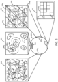
- FIG. 2 illustrates some examples of the surfaces 122.
- the different patterns of the surfaces 122 1 , 122 2 , 122 3 and 122 4 may be captured by respective representations 202, 204, and 206.
- FIG. 2 illustrates an object 106 with three different patterns formed on respective surfaces 122 1 , 122 2 , 122 3 and 122 4 , it should be noted that the surfaces 122 may all have the same pattern.
- the surface 122 1 may be captured as a two dimensional representation 202.
- the two dimensional representation 202 may be a photograph or video image that shows a unique pattern of the broken voxels of the surface 122 1 .
- the two dimensional representation 202 may be a black and white photograph or a color photograph.
- the surface 122 2 may be captured as a three dimensional representation 204.
- the three dimensional representation 204 may include various regions 206 1 to 206 o (hereinafter also referred to individually as a region 206 or collectively as regions 206). Each region 206 may represent a different elevation.
- the region 206 1 may represent a first elevation
- the region 206 2 may represent a second elevation
- the region 206 3 may represent a third elevation
- the three dimensional representation may be an actual three-dimensional representation.
- the representation 206 may be a digital image that can be rotated and moved to show the actual contours of the surface 122 2 .
- the surface 122 3 may be captured as a two-dimensional representation 208.
- the surface 122 3 may be designed to include different regions of color when printed on the 3D printer 102.
- a first region 210 1 may be a first color
- the region 210 2 may be a second color
- the region 210 3 may be a third color
- the region 210 4 may be a fourth color.
- the regions 210 1 and 210 3 may be a first color and the regions 210 2 and 210 4 may be a second color to create an alternating pattern of colors. Other patterns of color may also be used that are within the scope of the present disclosure.
- regions 210 1 to 210 4 are illustrates as diagonal stripes, it should be noted that the regions 210 1 to 210 4 may be printed as different colored voxels, in different shapes, in different shapes and sizes, and the like. The different colored regions 210 1 to 210 4 may provide an additional feature that can be used to identify the object 106 in addition to the unique pattern on the surface 208 created from the removal of the secondary structures 108.
- the surface 122 4 may be captured as two-dimensional representation 212.
- the two-dimensional representation 212 may include voxels 216 1 to 216 p (hereinafter also referred to individually as a voxel 216 or collectively as voxels 216) that are printed to appear as a machine readable code 214 when viewed at a macro level.
- voxels 216 1 to 216 p hereinafter also referred to individually as a voxel 216 or collectively as voxels 216) that are printed to appear as a machine readable code 214 when viewed at a macro level.
- the way the voxels 216 are printed within the surface 122 may be controlled.
- the voxels 216 may be fused differently, different colors may be used for different voxels 216, and the like.
- the voxels 216 may be printed such that when the secondary structure 108 is broken off, the voxels 216 in the surface 122 4 may appear as a machine readable code 214 (e.g., a QR code, a barcode, and the like).
- a machine readable code 214 e.g., a QR code, a barcode, and the like.
- techniques used herein may be combined. Specifically, techniques for micro details identifications as in 202, 204, 208 may be combined with 212 that may be used for macro identification. The later being easier to capture to guide the downstream processing of the object while the former may be harder to read and used only when full identification or authentication may be needed.
- the surfaces 122 may include a marking 220 located near, around, or below (e.g., via ultraviolet reactive voxels) the surfaces 122.
- the marking 220 may be printed during the printing of the object 106.
- the marking 220 may help to identify a location of the surface 122.
- the surfaces 122 may be relatively small compared to the overall size of the object 106. As a result, the marking 220 may help to identify where the surfaces 122 are located.
- the marking 220 may also be used by the object ID apparatus 126 to align a surface 122 with an optical device of the object ID apparatus 126.
- the marking 220 may include additional information that can be used to identify the 3D object. In some examples, the marking 220 may include identification of the 3D object that can be matched against identification information associated with a previously captured representation 124 that matches a representation of the surface 122 that is captured for identification.
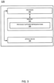
- FIG. 3 illustrates a block diagram of the object ID apparatus 126 of the present disclosure.
- the object ID apparatus 126 may include a processor 302, a memory 304, and an optical device 306.
- the processor 302 may be communicatively coupled to the memory 304 and the optical device 306.
- the processor 302 may execute instructions stored in the memory 304 and control operation of the optical device 306.
- the memory 304 may be a non-transitory computer readable medium.
- the memory 304 may be a hard disk drive, a solid state drive, a read only memory, a random access memory, and the like.
- the memory 304 may include previously captured representations 308.
- the previously captured representations 308 may include the representations 124 that were captured by the initial optical device 120.
- the previously captured representations 308 may be photographs, three dimensional representations, and the like, similar to the representations 124 described above in FIG. 1 .
- the optical device 306 may scan the surfaces 122 of the object 106.
- the optical device 306 may be a camera, a video camera, a 3D scanner, a depth sensing camera, and the like.
- the optical device 306 may capture two dimensional or three dimensional representations of the surfaces 122 on the object 106. X-ray may also be used.
- the object 106 may be placed within view of the optical device 306.
- the object 106 may be positioned such that a surface 122 of the object 106 can be captured by the optical device 306.
- the object 106 may be moved until the marking 220 is detected by the optical device 306.
- the optical device 306 may capture a representation of the surface 122.
- the processor 302 may then compare the captured representation to the previously captured representations 308. A match may be found and the previously captured representation 308 that matches the currently captured representation of the surface 122 may be used to identify the object 106.
- the initial optical device 120 may be the optical device 306.
- the object ID apparatus 126 may capture the initial representations 124 that identify an object, stored them as the previously captured representations 308 in the memory 304, and then perform the identification by capturing subsequent representations of the surfaces 122 of the object 106.
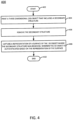
- FIG. 4 illustrates a flow diagram of an example method 400 for identifying an object based on a surface created from removal of a secondary structure from the object of the present disclosure.
- the method 400 may be performed by the apparatus 300 or the apparatus 500 illustrated in FIG. 5 , and described below.
- the method 400 begins.
- the method 400 prints a three-dimensional (3D) object that includes a secondary structure.
- the 3D object may be designed to include secondary structures that can be removed.
- the secondary structures may be printed with features that allows for easy removal of the secondary structure without damaging the 3D object.
- the secondary structure may be used for processing the 3D object.
- the secondary structure may prevent the part from deforming during the printing process, provide a handle to hold the part during post-processing, provide a label to identify the part during production, and the like.
- the secondary structures may include a sprue that is part of a frame.
- some 3D objects may have curved surfaces that use a frame to prevent the 3D object from moving during printing.
- the secondary structure may include support structures, printed label or printed label tag that can be removed, or any other secondary structure that can be removed.
- the method 400 removes the secondary structure.
- the secondary structure may be broken from the surface of the 3D object.
- a unique surface may be created in the area that of the 3D object that was connected to the secondary structure.
- no two breaks create the same pattern on the surface of the 3D object.
- the pattern created on the surface of the 3D object from breaking off the secondary structure can be used to identify or authenticate the 3D object.
- Identification of the 3D object can be used for tracking, quality control, and the like.
- Authentication of the 3D object can be used to verify the identity, to detect counterfeit parts, and the like.
- the pattern may include different colors.
- the area of the 3D object connected to the secondary structure may be printed with different colors, different colored regions, different colored shapes, different colored patterns, and the like, to create a unique pattern.
- different colors may be used down to a voxel level to create a unique pattern when the secondary structure is removed.
- the secondary structure may include a printed label that includes identification information of the 3D object.
- the 3D object may be associated with the secondary structure.
- the secondary structure can then be used to also perform identification at a later time. For example, the surface of the secondary structure created and the surface of the 3D object can be matched.
- the identification information on the secondary structure can then be used to identify and/or track the 3D object at a later time.
- the method 400 captures a representation of a surface of the 3D object where the secondary structure was removed, wherein the 3D object is authenticated based on the representation of the surface.
- the representation may be a 2D representation or a 3D representation.
- Examples of 2D representations may be a photograph or video image.
- Examples of a 3D representation may include an image that shows different topographies or contours of the surface of the 3D object where the secondary structure is removed.
- Other examples of 3D representations may include a digital image shows the actual height, geometries, contours, and the like of the surface. For example, the digital image can be rotated and moved to see the surface of the 3D object.
- the representation may be captured by an optical device that scans the surface.
- the optical device may be a camera, a 3D scanner, a depth sensing camera, and the like.
- the representation may be used to identify the 3D object.
- the representation may be associated with a particular 3D object and stored in memory.
- the surface or surfaces where the secondary structure is removed on the 3D object may be scanned to capture a representation.
- the recently captured representation may be compared to the stored representations that were previously captured. A match may be found to identify the 3D object at a later time.
- authentication may include a comparison of the representation to a previously captured representation of the surface of the 3D object where the secondary structure was removed. For example, if the 3D object may be known then the previously captured representation may be retrieved and compared to the currently captured representation to authenticate the 3D object.
- authentication may include identification of the 3D object. For example, if the 3D object is not known, then the representation may be compared to a plurality of previously captured representations to identify the previously captured representation that matches the representation that was recently captured.
- the representation may also include a corresponding surface of the secondary structure that was broken off.
- the secondary structure may be matched to the 3D object based on the corresponding surfaces.
- the information on the secondary structure that was kept may then be used to identify the 3D object or obtain additional information related to the 3D object (e.g., location within a block when printed, which 3D printer was used to print the 3D object, and so forth).
- the representation on the surface of the 3D object may include voxels that are arranged to appear as a QR code, 3D data matrices, or other type of encoding at a macro level. That representation on the surface of the 3D object can provide at least partial identification.
- the corresponding secondary structure may provide the additional identification of the 3D object (e.g., via its label).
- the micro level details of the surface and the macro level of details of the surface may be used in combination.
- the micro level details may include the unique features of how each voxel is torn when the secondary structure is removed.
- the macro level details may include how a group of voxels appear (e.g., a pattern of colors or arrangement of the voxels within a group of voxels).
- the micro level details may be used to identify the object via the representations, as described above.
- the macro level details e.g., the voxels that appear as a QR code
- the macro level details may provide an ID that is unique to a local workflow and the micro level details may have more fine details that provide for a global unique ID.
- the method 400 ends.
- FIG. 5 illustrates an example of an apparatus 500.
- the apparatus 500 may be the 3D printer 102.
- the apparatus 500 may include a processor 502 and a non-transitory computer readable storage medium 504.
- the non-transitory computer readable storage medium 504 may include instructions 506, 508, and 510 that, when executed by the processor 502, cause the processor 502 to perform various functions.
- the instructions 506 may include instructions to capture an image of a surface of a three-dimensional (3D) printed object, wherein the surface is created by removal of a secondary structure from the surface of the 3D printed object.
- the instructions 508 may include instructions to compare the image to a plurality of stored images.
- the instructions 510 may include instructions to authenticate the 3D printed object when the image matches a stored image of the plurality of stored images.
Landscapes
- Engineering & Computer Science (AREA)
- Physics & Mathematics (AREA)
- Chemical & Material Sciences (AREA)
- Materials Engineering (AREA)
- Manufacturing & Machinery (AREA)
- General Physics & Mathematics (AREA)
- Theoretical Computer Science (AREA)
- Optics & Photonics (AREA)
- Mechanical Engineering (AREA)
- Multimedia (AREA)
- Computer Vision & Pattern Recognition (AREA)
- Computer Security & Cryptography (AREA)
- Geometry (AREA)
- Computer Networks & Wireless Communication (AREA)
- Signal Processing (AREA)
Claims (11)
- Verfahren, das Folgendes umfasst:
Drucken eines dreidimensionalen (3D) Objekts (106), das eine Sekundärstruktur (108) einschließt:Entfernen der Sekundärstruktur (108) durch Brechen der Sekundärstruktur aus dem 3D-Objekt;Erfassen einer Darstellung (124) einer Oberfläche (122) des 3D-Objekts, wobei die Sekundärstruktur entfernt wurde, wobei das 3D-Objekt auf der Basis der Darstellung (124) der Oberfläche (122) authentifiziert wird. - Verfahren nach Anspruch 1, wobei die Sekundärstruktur (108) einen Angießkanal umfasst.
- Verfahren nach Anspruch 1, wobei die Sekundärstruktur (108) einen Abschnitt einer Stützstruktur umfasst.
- Verfahren nach Anspruch 1, wobei die Sekundärstruktur (108) eine gedruckte Etikettenmarkierung umfasst.
- Verfahren nach Anspruch 1, wobei die Darstellung (124) ein zweidimensionales Bild umfasst.
- Verfahren nach Anspruch 1, wobei die Darstellung (124) eine Messung geometrischer Merkmale der Oberfläche (122) umfasst.
- Verfahren nach Anspruch 1, wobei die Oberfläche eine Vielzahl von unterschiedlichen Farben umfasst, um ein einzigartiges Muster von Farben auf der Oberfläche (122) bereitzustellen.
- Nichtflüchtiges computerlesbar Speichermedium, das mit Anweisungen codiert ist, die durch einen Prozessor einer mobilen Vorrichtung ausführbar sind, wobei das nichtflüchtige computerlesbare Speichermedium Folgendes umfasst:Anweisungen, um ein Bild einer Oberfläche (122) eines dreidimensionalen (3D) gedruckten Objekts (106) zu erfassen, wobei die Oberfläche (122) durch Entfernen einer Sekundärstruktur (108) von der Oberfläche des 3D-gedruckten Objekts durch Abbrechen der Sekundärstruktur aus dem 3D-Objekt erzeugt wird;Anweisungen, um das Bild mit einer Vielzahl von gespeicherten Bildern zu vergleichen; undAnweisungen zum Authentifizieren des 3D-gedruckten Objekts, wenn das Bild mit einem gespeicherten Bild der Vielzahl von gespeicherten Bildern übereinstimmt.
- Nichtflüchtiges computerlesbares Speichermedium nach Anspruch 8, das ferner Folgendes umfasst:
Anweisungen zum Erkennen einer Markierung (124,220), die sich nahe der Oberfläche (122) befindet, wobei die Markierung (124,220) dazu dient, eine Position auf der Oberfläche (122) zu identifizieren, in der das Bild der Oberfläche (122) erfasst werden soll. - Nichtflüchtiges computerlesbares Speichermedium nach Anspruch 8, wobei das Bild ein Foto oder ein dreidimensionales Bild umfasst.
- Nichtflüchtiges computerlesbares Speichermedium nach Anspruch 8, wobei das Bild einen maschinenlesbaren Code umfasst, der durch Voxel innerhalb der Oberfläche (122) des 3D-gedruckten Objekts ausgebildet wird, wobei die Sekundärstruktur (108) entfernt wurde.
Priority Applications (2)
| Application Number | Priority Date | Filing Date | Title |
|---|---|---|---|
| EP20290007.2A EP3851268B1 (de) | 2020-01-17 | 2020-01-17 | Identifizierung von 3d-gedruckten objekten |
| US17/108,819 US11710327B2 (en) | 2020-01-17 | 2020-12-01 | Identification of 3D printed objects |
Applications Claiming Priority (1)
| Application Number | Priority Date | Filing Date | Title |
|---|---|---|---|
| EP20290007.2A EP3851268B1 (de) | 2020-01-17 | 2020-01-17 | Identifizierung von 3d-gedruckten objekten |
Publications (2)
| Publication Number | Publication Date |
|---|---|
| EP3851268A1 EP3851268A1 (de) | 2021-07-21 |
| EP3851268B1 true EP3851268B1 (de) | 2023-06-07 |
Family
ID=69571957
Family Applications (1)
| Application Number | Title | Priority Date | Filing Date |
|---|---|---|---|
| EP20290007.2A Active EP3851268B1 (de) | 2020-01-17 | 2020-01-17 | Identifizierung von 3d-gedruckten objekten |
Country Status (2)
| Country | Link |
|---|---|
| US (1) | US11710327B2 (de) |
| EP (1) | EP3851268B1 (de) |
Families Citing this family (3)
| Publication number | Priority date | Publication date | Assignee | Title |
|---|---|---|---|---|
| US11969945B2 (en) * | 2019-06-18 | 2024-04-30 | Hewlett-Packard Development Company, L.P. | Automated handling based on part identifier and location |
| US20230182400A1 (en) * | 2020-04-06 | 2023-06-15 | Hewlett-Packard Development Company, L.P. | Support structure generation for 3d printed objects |
| US20220122276A1 (en) * | 2020-10-21 | 2022-04-21 | Karam Peter | Forensic certification of artwork |
Family Cites Families (12)
| Publication number | Priority date | Publication date | Assignee | Title |
|---|---|---|---|---|
| US9208394B2 (en) | 2005-09-05 | 2015-12-08 | Alpvision S.A. | Authentication of an article of manufacture using an image of the microstructure of it surface |
| US8858856B2 (en) * | 2008-01-08 | 2014-10-14 | Stratasys, Inc. | Method for building and using three-dimensional objects containing embedded identification-tag inserts |
| US9290010B2 (en) | 2011-10-06 | 2016-03-22 | AI Cure Technologies, Inc. | Method and apparatus for fractal identification |
| US8630481B2 (en) | 2011-12-20 | 2014-01-14 | Eastman Kodak Company | Encoding information in illumination patterns |
| EP3096938B1 (de) | 2014-01-24 | 2023-09-20 | Verrana, Llc | Artikel und verfahren mit verwendung von 3d-drucken für fälschungsschutz |
| US10059053B2 (en) | 2014-11-04 | 2018-08-28 | Stratasys, Inc. | Break-away support material for additive manufacturing |
| US10218509B2 (en) * | 2015-03-02 | 2019-02-26 | Xerox Corporation | System to authenticate 3D printed objects |
| US9706076B2 (en) * | 2015-05-14 | 2017-07-11 | Xerox Corporation | 3D printer steganography |
| WO2018140004A1 (en) * | 2017-01-25 | 2018-08-02 | Hewlett-Packard Development Company, L.P. | Producing instructions that control three-dimensional printing from voxels |
| US11062118B2 (en) * | 2017-07-25 | 2021-07-13 | Alitheon, Inc. | Model-based digital fingerprinting |
| US11288471B2 (en) * | 2018-02-20 | 2022-03-29 | Chameleon Innovations Australia (Cia) Pty Ltd | Method for article authentication |
| DE102019115780B4 (de) * | 2019-06-11 | 2021-10-21 | Technische Universität Dresden | Verfahren und Vorrichtungen zum Mehrphotonendruck und zur Inspektion dreidimensionaler Strukturen |
-
2020
- 2020-01-17 EP EP20290007.2A patent/EP3851268B1/de active Active
- 2020-12-01 US US17/108,819 patent/US11710327B2/en active Active
Also Published As
| Publication number | Publication date |
|---|---|
| US11710327B2 (en) | 2023-07-25 |
| US20210224535A1 (en) | 2021-07-22 |
| EP3851268A1 (de) | 2021-07-21 |
Similar Documents
| Publication | Publication Date | Title |
|---|---|---|
| US11710327B2 (en) | Identification of 3D printed objects | |
| US11878540B2 (en) | Flexographic printing plate with persistent markings | |
| US8045753B2 (en) | Method of and system for authenticating an item | |
| EP3132919B1 (de) | Vorrichtung zur herstellung eines dreidimensionalen gefertigten objekts und herstellungsverfahren | |
| JP7341925B2 (ja) | 複合体系積層造形(cbam)画像品質(iq)の検証及び拒絶処理 | |
| US11504902B2 (en) | Methods and apparatus to identify additively manufactured parts | |
| US20110206269A1 (en) | Methods of evaluating the quality of two-dimensional matrix dot-peened marks on objects and mark verification systems | |
| US20190344506A1 (en) | Three-Dimensional Printing Method for Producing a Product Protected Against Forgery by Means of a Security Feature | |
| US20180143617A1 (en) | Method for printing colored object of 3d printer | |
| CN106461574A (zh) | 用于将印记施加到香烟包装上并对其进行检查的方法和设备 | |
| US20220363004A1 (en) | Generation of modified model data for three-dimensional printers | |
| WO2015022872A1 (ja) | 印刷のミクロ的輪郭形状を識別子とする個別物品の自動真贋判定方法 | |
| Shim et al. | Source identification of 3D printer based on layered texture encoders | |
| KR20190081391A (ko) | 증강현실을 이용한 3d 프린터 인쇄 물체 정보 표시 시스템 및 방법 | |
| EP3090877B1 (de) | Verfahren zur herstellung von substratausrichtungslaschen auf einer druckoberfläche | |
| JP7798164B2 (ja) | 読取装置、真贋判定装置、およびプログラム | |
| JP7684765B2 (ja) | 真正性および来歴追跡のための機械的にスタンプされた固有の特徴 | |
| WO2020190299A1 (en) | Processing merged 3d geometric information | |
| US12594727B2 (en) | Extrusion-based additive manufacturing: method and 3D printing system | |
| US11113590B2 (en) | Device and method for optimising transformation by digital processing of a substrate | |
| KR20170014531A (ko) | 3차원 프린팅 시스템 및 그 방법 | |
| WO2021173076A1 (en) | Identification tag | |
| KR101779265B1 (ko) | 2d사진에서 3d프린팅 기술을 이용하여 3차원적 얼굴 형상을 제작하는 방법 | |
| US11932038B2 (en) | Authentication system and method | |
| CN107206678B (zh) | 三维打印机中异常现象的检测 |
Legal Events
| Date | Code | Title | Description |
|---|---|---|---|
| PUAI | Public reference made under article 153(3) epc to a published international application that has entered the european phase |
Free format text: ORIGINAL CODE: 0009012 |
|
| STAA | Information on the status of an ep patent application or granted ep patent |
Free format text: STATUS: REQUEST FOR EXAMINATION WAS MADE |
|
| 17P | Request for examination filed |
Effective date: 20200130 |
|
| AK | Designated contracting states |
Kind code of ref document: A1 Designated state(s): AL AT BE BG CH CY CZ DE DK EE ES FI FR GB GR HR HU IE IS IT LI LT LU LV MC MK MT NL NO PL PT RO RS SE SI SK SM TR |
|
| STAA | Information on the status of an ep patent application or granted ep patent |
Free format text: STATUS: EXAMINATION IS IN PROGRESS |
|
| 17Q | First examination report despatched |
Effective date: 20220729 |
|
| RIN1 | Information on inventor provided before grant (corrected) |
Inventor name: SAYERS, CRAIG PETER Inventor name: HUANG, WEI Inventor name: DANEY DE MARCILLAC, PATRICK |
|
| REG | Reference to a national code |
Ref country code: DE Ref legal event code: R079 Free format text: PREVIOUS MAIN CLASS: B29C0064300000 Ipc: B29C0064386000 Ref country code: DE Ref legal event code: R079 Ref document number: 602020011820 Country of ref document: DE Free format text: PREVIOUS MAIN CLASS: B29C0064300000 Ipc: B29C0064386000 |
|
| RIC1 | Information provided on ipc code assigned before grant |
Ipc: B33Y 40/20 20200101ALI20221117BHEP Ipc: B29C 64/386 20170101AFI20221117BHEP |
|
| GRAP | Despatch of communication of intention to grant a patent |
Free format text: ORIGINAL CODE: EPIDOSNIGR1 |
|
| STAA | Information on the status of an ep patent application or granted ep patent |
Free format text: STATUS: GRANT OF PATENT IS INTENDED |
|
| INTG | Intention to grant announced |
Effective date: 20230223 |
|
| RIN1 | Information on inventor provided before grant (corrected) |
Inventor name: SAYERS, CRAIG PETER Inventor name: HUANG, WEI Inventor name: DANEY DE MARCILLAC, PATRICK |
|
| GRAS | Grant fee paid |
Free format text: ORIGINAL CODE: EPIDOSNIGR3 |
|
| GRAA | (expected) grant |
Free format text: ORIGINAL CODE: 0009210 |
|
| STAA | Information on the status of an ep patent application or granted ep patent |
Free format text: STATUS: THE PATENT HAS BEEN GRANTED |
|
| AK | Designated contracting states |
Kind code of ref document: B1 Designated state(s): AL AT BE BG CH CY CZ DE DK EE ES FI FR GB GR HR HU IE IS IT LI LT LU LV MC MK MT NL NO PL PT RO RS SE SI SK SM TR |
|
| REG | Reference to a national code |
Ref country code: GB Ref legal event code: FG4D |
|
| REG | Reference to a national code |
Ref country code: CH Ref legal event code: EP Ref country code: AT Ref legal event code: REF Ref document number: 1573763 Country of ref document: AT Kind code of ref document: T Effective date: 20230615 |
|
| REG | Reference to a national code |
Ref country code: DE Ref legal event code: R096 Ref document number: 602020011820 Country of ref document: DE |
|
| REG | Reference to a national code |
Ref country code: LT Ref legal event code: MG9D |
|
| REG | Reference to a national code |
Ref country code: NL Ref legal event code: MP Effective date: 20230607 |
|
| PG25 | Lapsed in a contracting state [announced via postgrant information from national office to epo] |
Ref country code: SE Free format text: LAPSE BECAUSE OF FAILURE TO SUBMIT A TRANSLATION OF THE DESCRIPTION OR TO PAY THE FEE WITHIN THE PRESCRIBED TIME-LIMIT Effective date: 20230607 Ref country code: NO Free format text: LAPSE BECAUSE OF FAILURE TO SUBMIT A TRANSLATION OF THE DESCRIPTION OR TO PAY THE FEE WITHIN THE PRESCRIBED TIME-LIMIT Effective date: 20230907 Ref country code: ES Free format text: LAPSE BECAUSE OF FAILURE TO SUBMIT A TRANSLATION OF THE DESCRIPTION OR TO PAY THE FEE WITHIN THE PRESCRIBED TIME-LIMIT Effective date: 20230607 |
|
| REG | Reference to a national code |
Ref country code: AT Ref legal event code: MK05 Ref document number: 1573763 Country of ref document: AT Kind code of ref document: T Effective date: 20230607 |
|
| PG25 | Lapsed in a contracting state [announced via postgrant information from national office to epo] |
Ref country code: RS Free format text: LAPSE BECAUSE OF FAILURE TO SUBMIT A TRANSLATION OF THE DESCRIPTION OR TO PAY THE FEE WITHIN THE PRESCRIBED TIME-LIMIT Effective date: 20230607 Ref country code: NL Free format text: LAPSE BECAUSE OF FAILURE TO SUBMIT A TRANSLATION OF THE DESCRIPTION OR TO PAY THE FEE WITHIN THE PRESCRIBED TIME-LIMIT Effective date: 20230607 Ref country code: LV Free format text: LAPSE BECAUSE OF FAILURE TO SUBMIT A TRANSLATION OF THE DESCRIPTION OR TO PAY THE FEE WITHIN THE PRESCRIBED TIME-LIMIT Effective date: 20230607 Ref country code: LT Free format text: LAPSE BECAUSE OF FAILURE TO SUBMIT A TRANSLATION OF THE DESCRIPTION OR TO PAY THE FEE WITHIN THE PRESCRIBED TIME-LIMIT Effective date: 20230607 Ref country code: HR Free format text: LAPSE BECAUSE OF FAILURE TO SUBMIT A TRANSLATION OF THE DESCRIPTION OR TO PAY THE FEE WITHIN THE PRESCRIBED TIME-LIMIT Effective date: 20230607 Ref country code: GR Free format text: LAPSE BECAUSE OF FAILURE TO SUBMIT A TRANSLATION OF THE DESCRIPTION OR TO PAY THE FEE WITHIN THE PRESCRIBED TIME-LIMIT Effective date: 20230908 |
|
| PG25 | Lapsed in a contracting state [announced via postgrant information from national office to epo] |
Ref country code: FI Free format text: LAPSE BECAUSE OF FAILURE TO SUBMIT A TRANSLATION OF THE DESCRIPTION OR TO PAY THE FEE WITHIN THE PRESCRIBED TIME-LIMIT Effective date: 20230607 |
|
| PG25 | Lapsed in a contracting state [announced via postgrant information from national office to epo] |
Ref country code: SK Free format text: LAPSE BECAUSE OF FAILURE TO SUBMIT A TRANSLATION OF THE DESCRIPTION OR TO PAY THE FEE WITHIN THE PRESCRIBED TIME-LIMIT Effective date: 20230607 |
|
| PG25 | Lapsed in a contracting state [announced via postgrant information from national office to epo] |
Ref country code: IS Free format text: LAPSE BECAUSE OF FAILURE TO SUBMIT A TRANSLATION OF THE DESCRIPTION OR TO PAY THE FEE WITHIN THE PRESCRIBED TIME-LIMIT Effective date: 20231007 |
|
| PG25 | Lapsed in a contracting state [announced via postgrant information from national office to epo] |
Ref country code: SM Free format text: LAPSE BECAUSE OF FAILURE TO SUBMIT A TRANSLATION OF THE DESCRIPTION OR TO PAY THE FEE WITHIN THE PRESCRIBED TIME-LIMIT Effective date: 20230607 Ref country code: SK Free format text: LAPSE BECAUSE OF FAILURE TO SUBMIT A TRANSLATION OF THE DESCRIPTION OR TO PAY THE FEE WITHIN THE PRESCRIBED TIME-LIMIT Effective date: 20230607 Ref country code: RO Free format text: LAPSE BECAUSE OF FAILURE TO SUBMIT A TRANSLATION OF THE DESCRIPTION OR TO PAY THE FEE WITHIN THE PRESCRIBED TIME-LIMIT Effective date: 20230607 Ref country code: PT Free format text: LAPSE BECAUSE OF FAILURE TO SUBMIT A TRANSLATION OF THE DESCRIPTION OR TO PAY THE FEE WITHIN THE PRESCRIBED TIME-LIMIT Effective date: 20231009 Ref country code: IS Free format text: LAPSE BECAUSE OF FAILURE TO SUBMIT A TRANSLATION OF THE DESCRIPTION OR TO PAY THE FEE WITHIN THE PRESCRIBED TIME-LIMIT Effective date: 20231007 Ref country code: EE Free format text: LAPSE BECAUSE OF FAILURE TO SUBMIT A TRANSLATION OF THE DESCRIPTION OR TO PAY THE FEE WITHIN THE PRESCRIBED TIME-LIMIT Effective date: 20230607 Ref country code: CZ Free format text: LAPSE BECAUSE OF FAILURE TO SUBMIT A TRANSLATION OF THE DESCRIPTION OR TO PAY THE FEE WITHIN THE PRESCRIBED TIME-LIMIT Effective date: 20230607 Ref country code: AT Free format text: LAPSE BECAUSE OF FAILURE TO SUBMIT A TRANSLATION OF THE DESCRIPTION OR TO PAY THE FEE WITHIN THE PRESCRIBED TIME-LIMIT Effective date: 20230607 |
|
| PG25 | Lapsed in a contracting state [announced via postgrant information from national office to epo] |
Ref country code: PL Free format text: LAPSE BECAUSE OF FAILURE TO SUBMIT A TRANSLATION OF THE DESCRIPTION OR TO PAY THE FEE WITHIN THE PRESCRIBED TIME-LIMIT Effective date: 20230607 |
|
| REG | Reference to a national code |
Ref country code: DE Ref legal event code: R097 Ref document number: 602020011820 Country of ref document: DE |
|
| PLBE | No opposition filed within time limit |
Free format text: ORIGINAL CODE: 0009261 |
|
| STAA | Information on the status of an ep patent application or granted ep patent |
Free format text: STATUS: NO OPPOSITION FILED WITHIN TIME LIMIT |
|
| PG25 | Lapsed in a contracting state [announced via postgrant information from national office to epo] |
Ref country code: DK Free format text: LAPSE BECAUSE OF FAILURE TO SUBMIT A TRANSLATION OF THE DESCRIPTION OR TO PAY THE FEE WITHIN THE PRESCRIBED TIME-LIMIT Effective date: 20230607 |
|
| PG25 | Lapsed in a contracting state [announced via postgrant information from national office to epo] |
Ref country code: SI Free format text: LAPSE BECAUSE OF FAILURE TO SUBMIT A TRANSLATION OF THE DESCRIPTION OR TO PAY THE FEE WITHIN THE PRESCRIBED TIME-LIMIT Effective date: 20230607 |
|
| 26N | No opposition filed |
Effective date: 20240308 |
|
| PG25 | Lapsed in a contracting state [announced via postgrant information from national office to epo] |
Ref country code: SI Free format text: LAPSE BECAUSE OF FAILURE TO SUBMIT A TRANSLATION OF THE DESCRIPTION OR TO PAY THE FEE WITHIN THE PRESCRIBED TIME-LIMIT Effective date: 20230607 Ref country code: IT Free format text: LAPSE BECAUSE OF FAILURE TO SUBMIT A TRANSLATION OF THE DESCRIPTION OR TO PAY THE FEE WITHIN THE PRESCRIBED TIME-LIMIT Effective date: 20230607 |
|
| PG25 | Lapsed in a contracting state [announced via postgrant information from national office to epo] |
Ref country code: MC Free format text: LAPSE BECAUSE OF FAILURE TO SUBMIT A TRANSLATION OF THE DESCRIPTION OR TO PAY THE FEE WITHIN THE PRESCRIBED TIME-LIMIT Effective date: 20230607 |
|
| PG25 | Lapsed in a contracting state [announced via postgrant information from national office to epo] |
Ref country code: MC Free format text: LAPSE BECAUSE OF FAILURE TO SUBMIT A TRANSLATION OF THE DESCRIPTION OR TO PAY THE FEE WITHIN THE PRESCRIBED TIME-LIMIT Effective date: 20230607 |
|
| REG | Reference to a national code |
Ref country code: CH Ref legal event code: PL |
|
| PG25 | Lapsed in a contracting state [announced via postgrant information from national office to epo] |
Ref country code: LU Free format text: LAPSE BECAUSE OF NON-PAYMENT OF DUE FEES Effective date: 20240117 |
|
| GBPC | Gb: european patent ceased through non-payment of renewal fee |
Effective date: 20240117 |
|
| PG25 | Lapsed in a contracting state [announced via postgrant information from national office to epo] |
Ref country code: LU Free format text: LAPSE BECAUSE OF NON-PAYMENT OF DUE FEES Effective date: 20240117 |
|
| PG25 | Lapsed in a contracting state [announced via postgrant information from national office to epo] |
Ref country code: GB Free format text: LAPSE BECAUSE OF NON-PAYMENT OF DUE FEES Effective date: 20240117 |
|
| PG25 | Lapsed in a contracting state [announced via postgrant information from national office to epo] |
Ref country code: BE Free format text: LAPSE BECAUSE OF NON-PAYMENT OF DUE FEES Effective date: 20240131 |
|
| PG25 | Lapsed in a contracting state [announced via postgrant information from national office to epo] |
Ref country code: FR Free format text: LAPSE BECAUSE OF NON-PAYMENT OF DUE FEES Effective date: 20240131 |
|
| PG25 | Lapsed in a contracting state [announced via postgrant information from national office to epo] |
Ref country code: CH Free format text: LAPSE BECAUSE OF NON-PAYMENT OF DUE FEES Effective date: 20240131 |
|
| PG25 | Lapsed in a contracting state [announced via postgrant information from national office to epo] |
Ref country code: GB Free format text: LAPSE BECAUSE OF NON-PAYMENT OF DUE FEES Effective date: 20240117 Ref country code: FR Free format text: LAPSE BECAUSE OF NON-PAYMENT OF DUE FEES Effective date: 20240131 Ref country code: CH Free format text: LAPSE BECAUSE OF NON-PAYMENT OF DUE FEES Effective date: 20240131 Ref country code: BE Free format text: LAPSE BECAUSE OF NON-PAYMENT OF DUE FEES Effective date: 20240131 |
|
| REG | Reference to a national code |
Ref country code: BE Ref legal event code: MM Effective date: 20240131 |
|
| PG25 | Lapsed in a contracting state [announced via postgrant information from national office to epo] |
Ref country code: BG Free format text: LAPSE BECAUSE OF FAILURE TO SUBMIT A TRANSLATION OF THE DESCRIPTION OR TO PAY THE FEE WITHIN THE PRESCRIBED TIME-LIMIT Effective date: 20230607 |
|
| PG25 | Lapsed in a contracting state [announced via postgrant information from national office to epo] |
Ref country code: BG Free format text: LAPSE BECAUSE OF FAILURE TO SUBMIT A TRANSLATION OF THE DESCRIPTION OR TO PAY THE FEE WITHIN THE PRESCRIBED TIME-LIMIT Effective date: 20230607 |
|
| PG25 | Lapsed in a contracting state [announced via postgrant information from national office to epo] |
Ref country code: IE Free format text: LAPSE BECAUSE OF NON-PAYMENT OF DUE FEES Effective date: 20240117 |
|
| PG25 | Lapsed in a contracting state [announced via postgrant information from national office to epo] |
Ref country code: IE Free format text: LAPSE BECAUSE OF NON-PAYMENT OF DUE FEES Effective date: 20240117 |
|
| PGFP | Annual fee paid to national office [announced via postgrant information from national office to epo] |
Ref country code: DE Payment date: 20241218 Year of fee payment: 6 |
|
| PG25 | Lapsed in a contracting state [announced via postgrant information from national office to epo] |
Ref country code: CY Free format text: LAPSE BECAUSE OF FAILURE TO SUBMIT A TRANSLATION OF THE DESCRIPTION OR TO PAY THE FEE WITHIN THE PRESCRIBED TIME-LIMIT; INVALID AB INITIO Effective date: 20200117 |
|
| PG25 | Lapsed in a contracting state [announced via postgrant information from national office to epo] |
Ref country code: HU Free format text: LAPSE BECAUSE OF FAILURE TO SUBMIT A TRANSLATION OF THE DESCRIPTION OR TO PAY THE FEE WITHIN THE PRESCRIBED TIME-LIMIT; INVALID AB INITIO Effective date: 20200117 |
|
| PG25 | Lapsed in a contracting state [announced via postgrant information from national office to epo] |
Ref country code: TR Free format text: LAPSE BECAUSE OF FAILURE TO SUBMIT A TRANSLATION OF THE DESCRIPTION OR TO PAY THE FEE WITHIN THE PRESCRIBED TIME-LIMIT Effective date: 20230607 |