EP3851355B1 - Axe portatif pour un bogie d'un véhicule ferroviaire - Google Patents
Axe portatif pour un bogie d'un véhicule ferroviaire Download PDFInfo
- Publication number
- EP3851355B1 EP3851355B1 EP20152390.9A EP20152390A EP3851355B1 EP 3851355 B1 EP3851355 B1 EP 3851355B1 EP 20152390 A EP20152390 A EP 20152390A EP 3851355 B1 EP3851355 B1 EP 3851355B1
- Authority
- EP
- European Patent Office
- Prior art keywords
- axle
- portal
- accordance
- bogie
- support
- Prior art date
- Legal status (The legal status is an assumption and is not a legal conclusion. Google has not performed a legal analysis and makes no representation as to the accuracy of the status listed.)
- Active
Links
Images


Classifications
-
- B—PERFORMING OPERATIONS; TRANSPORTING
- B61—RAILWAYS
- B61F—RAIL VEHICLE SUSPENSIONS, e.g. UNDERFRAMES, BOGIES OR ARRANGEMENTS OF WHEEL AXLES; RAIL VEHICLES FOR USE ON TRACKS OF DIFFERENT WIDTH; PREVENTING DERAILING OF RAIL VEHICLES; WHEEL GUARDS, OBSTRUCTION REMOVERS OR THE LIKE FOR RAIL VEHICLES
- B61F3/00—Types of bogies
- B61F3/16—Types of bogies with a separate axle for each wheel
-
- B—PERFORMING OPERATIONS; TRANSPORTING
- B61—RAILWAYS
- B61F—RAIL VEHICLE SUSPENSIONS, e.g. UNDERFRAMES, BOGIES OR ARRANGEMENTS OF WHEEL AXLES; RAIL VEHICLES FOR USE ON TRACKS OF DIFFERENT WIDTH; PREVENTING DERAILING OF RAIL VEHICLES; WHEEL GUARDS, OBSTRUCTION REMOVERS OR THE LIKE FOR RAIL VEHICLES
- B61F5/00—Constructional details of bogies; Connections between bogies and vehicle underframes; Arrangements or devices for adjusting or allowing self-adjustment of wheel axles or bogies when rounding curves
- B61F5/26—Mounting or securing axle-boxes in vehicle or bogie underframes
- B61F5/30—Axle-boxes mounted for movement under spring control in vehicle or bogie underframes
- B61F5/305—Axle-boxes mounted for movement under spring control in vehicle or bogie underframes incorporating rubber springs
Definitions
- the invention relates to the portal axle for a bogie of a rail vehicle, in particular a low-floor rail vehicle, with the features of the preamble of claim 1 and a bogie with such a portal axle.
- Portal axles of the type mentioned are well known from the prior art as parts of a bogie for a rail vehicle, in particular a low-floor rail vehicle.
- a portal axle of a bogie of a rail vehicle having a frame with support arms arranged at the ends of the frame.
- the support arm has a bridge which is pivotably arranged on the support arm, with primary spring assemblies being arranged on the inside of the bridge, which are fastened on the one hand to the bridge and on the other hand to the portal axle.
- the DE 2006 044 614 A1 discloses an axle with a swing arm solution in which the swing arms have gears that serve as wheel set bearings.
- the storage is thus designed as a so-called external storage, which is useful for rail vehicles that are operated on a so-called meter gauge. Steering knuckles with a respective axle shoulder are not disclosed, so that it can also be seen here that conventional solid axles only allow a small angle of rotation.
- one from the WO 2014/177417 A1 known bogie of a rail vehicle comprises a frame with a pivot bearing for the car body of the rail vehicle.
- Two portal axles are provided at a distance from one another on the frame, each of the portal axles having a spring arm at each of the two outwardly protruding ends.
- On the spring arm is a coil spring as the primary spring arranged on which the frame for receiving the pivot bearing is supported.
- the WO 2018/042326 A1 again shows a portal axle of a bogie, the portal axle having a steering knuckle at each end for receiving the wheel.
- the steering knuckle is approximately U-shaped with sloping flanks. Openings for receiving fastening means for fixing coil springs are provided in front of and behind the steering knuckle.
- a disadvantage of the design of the bogies with portal axles according to the three references mentioned above is that in the area of each wheel at least one, preferably two, vertically arranged primary springs are provided, on which the frame for accommodating the pivot bearing is supported, because the primary springs at least respective outer area of the rotary bearing limits the angle of rotation of the vehicle relative to the bogie.
- the DE 4 428 038 C1 also shows a bogie with a frame, the frame of the bogie having four individually suspended wheels to accommodate the pivot bearing for the car body.
- the wheels are each pivoted on the frame by a pivot arm.
- the frame is supported by frame supports on the swivel arm in the area of the wheel on a spring assembly, with the spring assembly sitting on the swivel arm at an angle.
- a portal axle in the true sense is not intended for this bogie.
- the object on which the invention is based is to provide a maximum angle of rotation while at the same time having a continuously level floor.
- the portal axle in order to support a frame of the bogie of the rail vehicle, on the one hand the portal axle has a swivel arm at both ends for the pivotable connection of the portal axle to the frame and on the other hand each of the two steering knuckles has a first axle shoulder with a spring device arranged thereon for resilient support of the frame on a support surface of the axle shoulder.
- the axle shoulder and the swivel arm are oriented to one another in such a way that a normal vector of the support surface and a longitudinal axis of the swivel arm enclose an angle of >0° but ⁇ 90°.
- the first shoulder of the steering knuckle is located locally above the pivot arm.
- the axle shoulder accommodates a spring device against which the frame of the bogie is supported.
- This spring device acts as a primary spring.
- the compact design of the portal axle with a steering knuckle arranged at each end on the portal axles with a first axle shoulder for accommodating the respective spring device means that the floor area can be designed flat throughout.
- the arrangement of the swivel arms on the portal axle is advantageously below the steering knuckle.
- the swivel arms are connected to a frame of the bogie.
- the first axle shoulder is to that Swivel arm immediately adjacent; or to put it another way, the first axle shoulder is located on the side of the steering knuckle facing the center of the bogie, on which in particular the swivel arm is also located.
- the arrangement of the inclined spring device at an angle of >0° but ⁇ 90°, and here in particular in an angular range of 30° to 60° and preferably of about 45°, ensures that the spring device is loaded evenly over its entire surface during compression becomes. This is because a circular arc section is described during the compression process.
- the portal axle has at least one support axle. This can be rectangular in cross section, for example. It is also conceivable to use several support axles that can run side by side.
- the at least one portal axle has a carrier at both ends for articulation on the at least one support axle.
- the carrier can be part of the carrying axle. If there are several support axles running parallel to one another, these are preferably accommodated by separate supports arranged at both ends.
- the steering knuckle is arranged on the support or is formed in one piece with it.
- the swivel arm can be arranged on the carrier or can be designed in one piece with it.
- a longitudinal axis of the steering knuckle is approximately parallel to the longitudinal axis of the swivel arm.
- the swivel arm has a bearing bush on the side of the bogie facing the frame.
- This bearing bush accommodates one end of a frame traverse, which shows a bearing block with two bearing flanges at both ends to be received by the respective bearing bush, the bearing flanges serving to accommodate an axle stub which is rotatably mounted in the bearing bush.
- the bearing block can be part of the frame.
- the frame traverse is part of the frame.
- the frame can optionally include a rotary bearing, by means of which a car body is rotatably accommodated on the frame, as a result of which greater angles of rotation of the car body can also be achieved.
- the stub axle has a second axle shoulder, which is designed to run obliquely towards the first axle shoulder.
- an end face of the second axle shoulder is—in a projection onto a plane transverse to the main direction of extent of the support axle—inclined to the support surface of the first axle shoulder.
- the steering knuckle is designed approximately in the manner of a trapezoid or triangle in the view, with the flanks of this steering knuckle, which are designed to run towards one another at an angle, forming the first and the second axle shoulder.
- the oblique course of the second axle shoulder in the direction of the first axle shoulder causes a relatively larger rotation angle of the bogie due to the free space created in this way behind the steering knuckle to the car body is made possible, which allows driving through tight curves.
- the steering knuckle can taper at least in sections starting from the axle shoulder in the direction of the longitudinal axis.
- first side surface of the steering knuckle is designed to run obliquely, increasing the distance from the second, opposite side surface. As already explained elsewhere, this provides the maximum possible space for the angle of rotation.
- the steering knuckle has a bearing element for bearingly receiving a wheel or wheel stub axle of the wheel.
- the bearing element can be a bearing journal or bolt.
- the steering knuckle accommodates a spring device on the first axle shoulder.
- This spring device is in particular formed from a plurality of elastomer spring assemblies which are arranged one above the other. This means that several elastomer cushions are provided in each case, which are separated from one another by a metal plate, so the spring device is designed similar to a rubber-metal bearing. It can be provided here that the stiffness of the elastomer spring assemblies or elastomer cushions is the same or different. This means that the spring characteristic can be influenced by selecting the elasticity of the individual elastomer spring assemblies.
- the invention also relates to a bogie of a rail vehicle, in particular a low-floor rail vehicle, with two portal axles according to the invention spaced apart from one another in the longitudinal direction of the vehicle, a frame for receiving the car body being provided between the portal axles of the bogie.
- the bogie may include a pivot bearing carried by a cradle on the frame. The pivot bearing means that the car body can be rotated relative to the frame, which means that the car body can also rotate at a larger angle.
- the frame can be connected to the respective swivel arms of the two portal axles by the respective frame traverses.
- the connection can be made by means of the bearing bushings provided at the ends of the swivel arms, which enable the swiveling connection of the frame traverse to the corresponding portal axle.
- the frame has a spring arm at each of its four ends, which is connected to the spring device on the first axle shoulder of the respective steering knuckle. It is clear from this that each portal axis can be pivoted about the two bearing bushes assigned to it on a circular path against the force of the respective spring device.
- the arrangement of the swivel arms on the portal axle, and here in particular the supports of the portal axle, takes place below the steering knuckle. In this respect, a relatively large level and low-floor floor is thereby provided.
- This in 1 Bogie designated 1 has a frame 3, the frame 3 being connected at both ends to a respective portal axle 20.
- the frame 3 itself has two frame supports 4 running parallel to one another, each with a spring arm 5 at the end.
- a pivot bearing traverse 7 is arranged, on which the pivot bearing 9 is shown schematically.
- the pivot bearing traverse 7 via in figure 1 secondary springs, not shown, may be supported on the frame support 4 .
- the pivot bearing 9 is used to rotatably accommodate the car body, not shown.
- a frame traverse 11 runs parallel to the respective portal axis and is articulated at the end to the frame supports 4 .
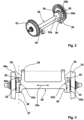
- the portal axle 20 comprises a cross-sectionally rectangular support axle 22, which extends in a main extension direction 22a and has a support 24 ( 4 ) having.
- a swivel arm 29 is arranged on the support 24 in the direction of a longitudinal axis 27 and is provided with a bearing bush 30 at the end.
- the steering knuckle 32 which receives the wheel 33 , is fastened to the carrier 24 .
- the two swivel arms 29 connect the portal axle 20 to the frame 3 of the bogie 1 .
- a bearing block 13 is provided on the frame traverse 11 in the area of each swivel arm 29, which comprises two bearing flanges 15 which accommodate an axle stub 16 which is located in the bearing bush 30 of the swivel arm 29 is rotatably mounted.
- the steering knuckle 32 includes a first axle shoulder 35 for accommodating a spring device 37 .
- the frame supports 4 each have the spring arm 5 at the end, which is connected to the spring device 37 .
- the spring arms 5 are thus resiliently supported on support surfaces 35a of the respectively associated first axle shoulder 35.
- the spring device 37 comprises individual elastomer spring assemblies 38 which are each separated from one another by metal plates 38a.
- the first axle shoulder 35 which serves to accommodate the spring device 37, and specifically the normal vector 35b of the support surface 35a runs at an angle ⁇ of approximately 45° to the longitudinal axis 27 of the swivel arm 29.
- a second axle shoulder 36 is provided, which runs obliquely towards the first axle shoulder 35, so that the steering knuckle 32 is approximately trapezoidal or triangular in the view.
- the oblique course of the second axle shoulder 36 in the direction of the first axle shoulder 35 creates a free space in the area of the second axle shoulder 36, which causes the angle of rotation of the car body relative to the bogie to be increased, with the result that such a vehicle can negotiate tight curves can drive through.
- the spring device 37 on the first axle shoulder 35 forms the primary spring device, without a further spring having to be provided in the region of the second axle shoulder, as is sometimes the case in the prior art.
- This also means that the space available in the area of the second axle shoulder benefits from a larger rotation angle.
- the stub axle 32 is designed to widen in the direction of the first axle shoulder 35 , specifically in that the side surface 32a of the stub axle running on the inside runs at an angle to the longitudinal axis 27 . This increases the available installation space in the direction of the ends of the bogie 1, with the result that the angle of rotation of the car body increases relative to the bogie.
Landscapes
- Engineering & Computer Science (AREA)
- Mechanical Engineering (AREA)
- Platform Screen Doors And Railroad Systems (AREA)
Claims (15)
- Pont-portique (20) pour un bogie (1) d'un véhicule ferroviaire, en particulier d'un véhicule ferroviaire à plancher surbaissé, le pont-portique (20) présentant, aux deux extrémités, respectivement une fusée d'essieu (32),
caractérisé en ce que,
pour le support d'un châssis (3) du bogie du véhicule ferroviaire,• le pont-portique (20) présente, aux deux extrémités, respectivement un bras pivotant (29) pour la liaison pivotante du pont-portique (20) au châssis (3) et• chacune des deux fusées d'essieu (32) présente un premier épaulement d'essieu (35) avec un dispositif à ressorts (37) disposé sur celui-ci pour le support sur ressort du châssis (3) sur une surface d'appui (35a) de l'épaulement d'essieu (35),les épaulements d'essieu (35) et le bras pivotant (29) étant orientés les uns par rapport aux autres de telle manière qu'un vecteur normal (35b) de la surface d'appui (35a) et un axe longitudinal (27) du bras pivotant (29) forment un angle (α) de > 0° mais < 90°. - Pont-portique (20) selon la revendication 1,
caractérisé en ce que
le pont-portique (20) présente au moins un essieu porteur (22) qui s'étend entre les deux fusées d'essieu (32). - Pont-portique (20) selon l'une des revendications précédentes,
caractérisé en ce que
le bras pivotant (29) présente un coussinet (30) pour le logement sur palier du châssis (3). - Pont-portique (20) selon l'une des revendications précédentes,
caractérisé en ce que
la fusée d'essieu (32) s'amincit, au moins sur certaines parties, à partir de l'épaulement d'essieu (35) en direction de l'axe longitudinal (27). - Pont-portique (20) selon la revendication 4,
caractérisé en ce que- lors d'une projection sur un plan qui contient l'axe longitudinal (27) et une direction d'extension principale (22a) d'un/de l'essieu porteur (22) du pont-portique (20) -• une première surface latérale (32a) de la fusée d'essieu (32) située dans la direction de l'essieu porteur (22) est inclinée par rapport à la direction d'extension principale (22a) et• une seconde surface latérale (32b) opposée de la fusée d'essieu (32) est orientée sensiblement transversalement à la direction d'extension principale (22a). - Pont-portique (20) selon l'une des revendications précédentes,
caractérisé en ce que
l'au moins un pont-portique (20) présente, aux deux extrémités, respectivement une poutre (24) pour l'articulation d'un/de l'essieu porteur (22) du pont-portique (22). - Pont-portique (20) selon la revendication 6,
caractérisé en ce que
la fusée d'essieu (32) et/ou le bras pivotant (29) est/sont disposés sur ou contre la poutre (24). - Pont-portique (20) selon l'une des revendications précédentes,
caractérisé en ce que
la fusée d'essieu (32) présente un second épaulement d'essieu (36), dont la surface frontale (36a) - dans une projection sur un plan transversal à la direction d'extension principale (22a) de l'essieu porteur (22) - est inclinée par rapport à la surface d'appui (35a) du premier épaulement d'essieu (35). - Pont-portique (20) selon l'une des revendications précédentes,
caractérisé en ce que
la fusée d'essieu (32) présente un élément de palier pour le logement sur palier d'une roue (33) du pont-portique (20). - Pont-portique (20) selon l'une des revendications précédentes,
caractérisé en ce que
le dispositif à ressorts (37) présente au moins un, de préférence plusieurs blocs-ressorts (38) en élastomère disposés les uns au-dessus des autres. - Pont-portique (20) selon la revendication 10,
caractérisé en ce que
la rigidité des blocs-ressorts (38) en élastomère est identique ou n'est pas identique. - Pont-portique (20) selon l'une des revendications précédentes,
caractérisé en ce que
l'angle (α) entre le vecteur normal (35b) et l'axe longitudinal (27) est compris entre 30° et 60°. - Bogie (1) pour un véhicule ferroviaire, en particulier un véhicule ferroviaire à plancher surbaissé, comportant deux ponts-portiques (20) selon l'une des revendications précédentes, disposés espacés l'un de l'autre dans la direction longitudinale du véhicule ferroviaire, caractérisé en ce que
un châssis (3) pour recevoir une caisse de wagon du véhicule ferroviaire est prévu entre les ponts-portiques (20) du bogie (1), un palier rotatif (9) étant prévu en option pour le logement rotatif de la caisse de wagon. - Bogie (1) selon la revendication 13,
caractérisé en ce que
le châssis (3) est relié aux bras pivotants (29) respectifs des deux ponts-portiques (20), en particulier au moyen des coussinets (30) des bras pivotants (29). - Bogie (1) selon la revendication 13 ou 14,
caractérisé en ce que
le châssis (3) présente, aux deux extrémités, respectivement deux bras à ressort (5) qui sont reliés au dispositif à ressorts (37) respectif.
Priority Applications (1)
| Application Number | Priority Date | Filing Date | Title |
|---|---|---|---|
| EP20152390.9A EP3851355B1 (fr) | 2020-01-17 | 2020-01-17 | Axe portatif pour un bogie d'un véhicule ferroviaire |
Applications Claiming Priority (1)
| Application Number | Priority Date | Filing Date | Title |
|---|---|---|---|
| EP20152390.9A EP3851355B1 (fr) | 2020-01-17 | 2020-01-17 | Axe portatif pour un bogie d'un véhicule ferroviaire |
Publications (3)
| Publication Number | Publication Date |
|---|---|
| EP3851355A1 EP3851355A1 (fr) | 2021-07-21 |
| EP3851355B1 true EP3851355B1 (fr) | 2023-06-07 |
| EP3851355C0 EP3851355C0 (fr) | 2023-06-07 |
Family
ID=69191857
Family Applications (1)
| Application Number | Title | Priority Date | Filing Date |
|---|---|---|---|
| EP20152390.9A Active EP3851355B1 (fr) | 2020-01-17 | 2020-01-17 | Axe portatif pour un bogie d'un véhicule ferroviaire |
Country Status (1)
| Country | Link |
|---|---|
| EP (1) | EP3851355B1 (fr) |
Families Citing this family (1)
| Publication number | Priority date | Publication date | Assignee | Title |
|---|---|---|---|---|
| FR3129352B1 (fr) | 2021-11-25 | 2023-11-24 | Alstom Transp Tech | Bogie de véhicule ferroviaire à encombrement réduit |
Family Cites Families (7)
| Publication number | Priority date | Publication date | Assignee | Title |
|---|---|---|---|---|
| DE4428038C1 (de) | 1994-08-08 | 1995-08-10 | Siemens Ag | Fahrwerk für ein Schienenfahrzeug |
| DE102006044614A1 (de) * | 2006-09-19 | 2008-03-27 | Sames, Gerhold, Dipl.-Ing. | Radführungseinheit mit und ohne Antriebseinheit |
| JP5322775B2 (ja) * | 2009-05-26 | 2013-10-23 | 川崎重工業株式会社 | 低床式鉄道車両用台車、それの固定車軸の圧入方法および取り外し方法 |
| ES2880707T3 (es) * | 2012-05-30 | 2021-11-25 | Bombardier Transp Gmbh | Bastidor de tren de rodaje para vehículo ferroviario |
| AT514373B1 (de) | 2013-05-02 | 2019-03-15 | Siemens Ag Oesterreich | Radsatzlagerung für den Radsatz eines Schienenfahrzeugs mit innengelagertem Drehgestell |
| IT201600088005A1 (it) | 2016-08-30 | 2018-03-02 | Lucchini Rs Spa | Ponte-assale di veicoli ferroviari e ferrotranviari a pianale ribassato |
| DE102017128598B4 (de) | 2017-12-01 | 2019-10-31 | Andreas Fiedler | Anordnung zum Dämpfen des Wankens und zum Querstabilisieren eines Wagenkastens für Landfahrzeuge |
-
2020
- 2020-01-17 EP EP20152390.9A patent/EP3851355B1/fr active Active
Also Published As
| Publication number | Publication date |
|---|---|
| EP3851355A1 (fr) | 2021-07-21 |
| EP3851355C0 (fr) | 2023-06-07 |
Similar Documents
| Publication | Publication Date | Title |
|---|---|---|
| DE2912533A1 (de) | Achsfederung | |
| EP3065958B1 (fr) | Suspension de roue pour véhicule automobile | |
| DE2246542B2 (de) | Federung für Fahrzeuge | |
| DE102005029641A1 (de) | Radaufhängung | |
| DE202015008095U1 (de) | Tandemachse | |
| EP3851355B1 (fr) | Axe portatif pour un bogie d'un véhicule ferroviaire | |
| DE102016003885B4 (de) | Radaufhängung für einen Mobilkran | |
| DE1755070C3 (de) | Radaufhängung für Kraftfahrzeuge | |
| WO2006040017A1 (fr) | Suspension de roue independante d'un vehicule a double voie | |
| DE10260060A1 (de) | Einzelradaufhängung mit Blattfeder für ein Kraftfahrzeug | |
| DE3221755C2 (fr) | ||
| DE102018207616B4 (de) | Radaufhängung für ein Kraftfahrzeug | |
| DE3442682C2 (fr) | ||
| DE102012001377A1 (de) | Ballastwagen für einen Derrickkran | |
| EP1118477A2 (fr) | Suspension de roue | |
| DE102021121993B3 (de) | Radaufhängung für ein Kraftfahrzeug sowie entsprechendes Kraftfahrzeug | |
| DE19853636B4 (de) | Radaufhängung | |
| DE102015222041A1 (de) | Starrachsaufhängung für ein Landfahrzeug | |
| DE69715550T2 (de) | Vorrichtung einer Pseudo- Mac Pherson- Bauart- Kraftfahrzeugaufhängung | |
| WO2020221569A1 (fr) | Suspension indépendante pour un véhicule à deux voies, essieu et véhicule | |
| EP1226058B1 (fr) | Bogie pour vehicules sur rails | |
| DE19535521A1 (de) | Verbundlenkerachse für die Hinterräder eines Kraftfahrzeugs | |
| EP0697297A2 (fr) | Essieux en tandem d'un véhicule utilitaire avec support spécial à ressort à lames | |
| DE2127846C3 (de) | Drehgestell für Schienenfahrzeuge | |
| DE102013222443A1 (de) | Radaufhängung für ein Kraftfahrzeug |
Legal Events
| Date | Code | Title | Description |
|---|---|---|---|
| PUAI | Public reference made under article 153(3) epc to a published international application that has entered the european phase |
Free format text: ORIGINAL CODE: 0009012 |
|
| STAA | Information on the status of an ep patent application or granted ep patent |
Free format text: STATUS: REQUEST FOR EXAMINATION WAS MADE |
|
| 17P | Request for examination filed |
Effective date: 20210128 |
|
| AK | Designated contracting states |
Kind code of ref document: A1 Designated state(s): AL AT BE BG CH CY CZ DE DK EE ES FI FR GB GR HR HU IE IS IT LI LT LU LV MC MK MT NL NO PL PT RO RS SE SI SK SM TR |
|
| GRAP | Despatch of communication of intention to grant a patent |
Free format text: ORIGINAL CODE: EPIDOSNIGR1 |
|
| STAA | Information on the status of an ep patent application or granted ep patent |
Free format text: STATUS: GRANT OF PATENT IS INTENDED |
|
| INTG | Intention to grant announced |
Effective date: 20221201 |
|
| GRAS | Grant fee paid |
Free format text: ORIGINAL CODE: EPIDOSNIGR3 |
|
| GRAA | (expected) grant |
Free format text: ORIGINAL CODE: 0009210 |
|
| STAA | Information on the status of an ep patent application or granted ep patent |
Free format text: STATUS: THE PATENT HAS BEEN GRANTED |
|
| AK | Designated contracting states |
Kind code of ref document: B1 Designated state(s): AL AT BE BG CH CY CZ DE DK EE ES FI FR GB GR HR HU IE IS IT LI LT LU LV MC MK MT NL NO PL PT RO RS SE SI SK SM TR |
|
| REG | Reference to a national code |
Ref country code: GB Ref legal event code: FG4D Free format text: NOT ENGLISH |
|
| REG | Reference to a national code |
Ref country code: CH Ref legal event code: EP Ref country code: AT Ref legal event code: REF Ref document number: 1574136 Country of ref document: AT Kind code of ref document: T Effective date: 20230615 Ref country code: DE Ref legal event code: R096 Ref document number: 502020003420 Country of ref document: DE |
|
| U01 | Request for unitary effect filed |
Effective date: 20230607 |
|
| U07 | Unitary effect registered |
Designated state(s): AT BE BG DE DK EE FI FR IT LT LU LV MT NL PT SE SI Effective date: 20230612 |
|
| REG | Reference to a national code |
Ref country code: LT Ref legal event code: MG9D |
|
| PG25 | Lapsed in a contracting state [announced via postgrant information from national office to epo] |
Ref country code: NO Free format text: LAPSE BECAUSE OF FAILURE TO SUBMIT A TRANSLATION OF THE DESCRIPTION OR TO PAY THE FEE WITHIN THE PRESCRIBED TIME-LIMIT Effective date: 20230907 Ref country code: ES Free format text: LAPSE BECAUSE OF FAILURE TO SUBMIT A TRANSLATION OF THE DESCRIPTION OR TO PAY THE FEE WITHIN THE PRESCRIBED TIME-LIMIT Effective date: 20230607 |
|
| PG25 | Lapsed in a contracting state [announced via postgrant information from national office to epo] |
Ref country code: RS Free format text: LAPSE BECAUSE OF FAILURE TO SUBMIT A TRANSLATION OF THE DESCRIPTION OR TO PAY THE FEE WITHIN THE PRESCRIBED TIME-LIMIT Effective date: 20230607 Ref country code: HR Free format text: LAPSE BECAUSE OF FAILURE TO SUBMIT A TRANSLATION OF THE DESCRIPTION OR TO PAY THE FEE WITHIN THE PRESCRIBED TIME-LIMIT Effective date: 20230607 Ref country code: GR Free format text: LAPSE BECAUSE OF FAILURE TO SUBMIT A TRANSLATION OF THE DESCRIPTION OR TO PAY THE FEE WITHIN THE PRESCRIBED TIME-LIMIT Effective date: 20230908 |
|
| PG25 | Lapsed in a contracting state [announced via postgrant information from national office to epo] |
Ref country code: SK Free format text: LAPSE BECAUSE OF FAILURE TO SUBMIT A TRANSLATION OF THE DESCRIPTION OR TO PAY THE FEE WITHIN THE PRESCRIBED TIME-LIMIT Effective date: 20230607 |
|
| PG25 | Lapsed in a contracting state [announced via postgrant information from national office to epo] |
Ref country code: IS Free format text: LAPSE BECAUSE OF FAILURE TO SUBMIT A TRANSLATION OF THE DESCRIPTION OR TO PAY THE FEE WITHIN THE PRESCRIBED TIME-LIMIT Effective date: 20231007 |
|
| PG25 | Lapsed in a contracting state [announced via postgrant information from national office to epo] |
Ref country code: SM Free format text: LAPSE BECAUSE OF FAILURE TO SUBMIT A TRANSLATION OF THE DESCRIPTION OR TO PAY THE FEE WITHIN THE PRESCRIBED TIME-LIMIT Effective date: 20230607 Ref country code: SK Free format text: LAPSE BECAUSE OF FAILURE TO SUBMIT A TRANSLATION OF THE DESCRIPTION OR TO PAY THE FEE WITHIN THE PRESCRIBED TIME-LIMIT Effective date: 20230607 Ref country code: RO Free format text: LAPSE BECAUSE OF FAILURE TO SUBMIT A TRANSLATION OF THE DESCRIPTION OR TO PAY THE FEE WITHIN THE PRESCRIBED TIME-LIMIT Effective date: 20230607 Ref country code: IS Free format text: LAPSE BECAUSE OF FAILURE TO SUBMIT A TRANSLATION OF THE DESCRIPTION OR TO PAY THE FEE WITHIN THE PRESCRIBED TIME-LIMIT Effective date: 20231007 Ref country code: CZ Free format text: LAPSE BECAUSE OF FAILURE TO SUBMIT A TRANSLATION OF THE DESCRIPTION OR TO PAY THE FEE WITHIN THE PRESCRIBED TIME-LIMIT Effective date: 20230607 |
|
| U20 | Renewal fee for the european patent with unitary effect paid |
Year of fee payment: 5 Effective date: 20240119 |
|
| PG25 | Lapsed in a contracting state [announced via postgrant information from national office to epo] |
Ref country code: PL Free format text: LAPSE BECAUSE OF FAILURE TO SUBMIT A TRANSLATION OF THE DESCRIPTION OR TO PAY THE FEE WITHIN THE PRESCRIBED TIME-LIMIT Effective date: 20230607 |
|
| REG | Reference to a national code |
Ref country code: DE Ref legal event code: R097 Ref document number: 502020003420 Country of ref document: DE |
|
| PLBE | No opposition filed within time limit |
Free format text: ORIGINAL CODE: 0009261 |
|
| STAA | Information on the status of an ep patent application or granted ep patent |
Free format text: STATUS: NO OPPOSITION FILED WITHIN TIME LIMIT |
|
| 26N | No opposition filed |
Effective date: 20240308 |
|
| PG25 | Lapsed in a contracting state [announced via postgrant information from national office to epo] |
Ref country code: MC Free format text: LAPSE BECAUSE OF FAILURE TO SUBMIT A TRANSLATION OF THE DESCRIPTION OR TO PAY THE FEE WITHIN THE PRESCRIBED TIME-LIMIT Effective date: 20230607 |
|
| PG25 | Lapsed in a contracting state [announced via postgrant information from national office to epo] |
Ref country code: MC Free format text: LAPSE BECAUSE OF FAILURE TO SUBMIT A TRANSLATION OF THE DESCRIPTION OR TO PAY THE FEE WITHIN THE PRESCRIBED TIME-LIMIT Effective date: 20230607 |
|
| REG | Reference to a national code |
Ref country code: CH Ref legal event code: PL |
|
| GBPC | Gb: european patent ceased through non-payment of renewal fee |
Effective date: 20240117 |
|
| PG25 | Lapsed in a contracting state [announced via postgrant information from national office to epo] |
Ref country code: GB Free format text: LAPSE BECAUSE OF NON-PAYMENT OF DUE FEES Effective date: 20240117 |
|
| PG25 | Lapsed in a contracting state [announced via postgrant information from national office to epo] |
Ref country code: CH Free format text: LAPSE BECAUSE OF NON-PAYMENT OF DUE FEES Effective date: 20240131 |
|
| PG25 | Lapsed in a contracting state [announced via postgrant information from national office to epo] |
Ref country code: GB Free format text: LAPSE BECAUSE OF NON-PAYMENT OF DUE FEES Effective date: 20240117 Ref country code: CH Free format text: LAPSE BECAUSE OF NON-PAYMENT OF DUE FEES Effective date: 20240131 |
|
| PG25 | Lapsed in a contracting state [announced via postgrant information from national office to epo] |
Ref country code: IE Free format text: LAPSE BECAUSE OF NON-PAYMENT OF DUE FEES Effective date: 20240117 |
|
| PG25 | Lapsed in a contracting state [announced via postgrant information from national office to epo] |
Ref country code: IE Free format text: LAPSE BECAUSE OF NON-PAYMENT OF DUE FEES Effective date: 20240117 |
|
| U20 | Renewal fee for the european patent with unitary effect paid |
Year of fee payment: 6 Effective date: 20250127 |
|
| PG25 | Lapsed in a contracting state [announced via postgrant information from national office to epo] |
Ref country code: CY Free format text: LAPSE BECAUSE OF FAILURE TO SUBMIT A TRANSLATION OF THE DESCRIPTION OR TO PAY THE FEE WITHIN THE PRESCRIBED TIME-LIMIT; INVALID AB INITIO Effective date: 20200117 |
|
| PG25 | Lapsed in a contracting state [announced via postgrant information from national office to epo] |
Ref country code: HU Free format text: LAPSE BECAUSE OF FAILURE TO SUBMIT A TRANSLATION OF THE DESCRIPTION OR TO PAY THE FEE WITHIN THE PRESCRIBED TIME-LIMIT; INVALID AB INITIO Effective date: 20200117 |
|
| PG25 | Lapsed in a contracting state [announced via postgrant information from national office to epo] |
Ref country code: TR Free format text: LAPSE BECAUSE OF FAILURE TO SUBMIT A TRANSLATION OF THE DESCRIPTION OR TO PAY THE FEE WITHIN THE PRESCRIBED TIME-LIMIT Effective date: 20230607 |
|
| U20 | Renewal fee for the european patent with unitary effect paid |
Year of fee payment: 7 Effective date: 20260128 |