EP3851369A1 - Seeschiff - Google Patents
Seeschiff Download PDFInfo
- Publication number
- EP3851369A1 EP3851369A1 EP21150213.3A EP21150213A EP3851369A1 EP 3851369 A1 EP3851369 A1 EP 3851369A1 EP 21150213 A EP21150213 A EP 21150213A EP 3851369 A1 EP3851369 A1 EP 3851369A1
- Authority
- EP
- European Patent Office
- Prior art keywords
- propeller
- marine vessel
- hull
- propellers
- pod type
- Prior art date
- Legal status (The legal status is an assumption and is not a legal conclusion. Google has not performed a legal analysis and makes no representation as to the accuracy of the status listed.)
- Withdrawn
Links
- XLYOFNOQVPJJNP-UHFFFAOYSA-N water Substances O XLYOFNOQVPJJNP-UHFFFAOYSA-N 0.000 claims abstract description 13
- 230000000694 effects Effects 0.000 description 11
- 238000011144 upstream manufacturing Methods 0.000 description 3
- 230000033228 biological regulation Effects 0.000 description 2
- 239000000446 fuel Substances 0.000 description 2
- 238000009434 installation Methods 0.000 description 2
- 238000000034 method Methods 0.000 description 2
- 229910052717 sulfur Inorganic materials 0.000 description 2
- 239000011593 sulfur Substances 0.000 description 2
- 239000000654 additive Substances 0.000 description 1
- 230000000996 additive effect Effects 0.000 description 1
- 230000000052 comparative effect Effects 0.000 description 1
- 238000005457 optimization Methods 0.000 description 1
- 230000002093 peripheral effect Effects 0.000 description 1
- 230000001141 propulsive effect Effects 0.000 description 1
Images


Classifications
-
- B—PERFORMING OPERATIONS; TRANSPORTING
- B63—SHIPS OR OTHER WATERBORNE VESSELS; RELATED EQUIPMENT
- B63H—MARINE PROPULSION OR STEERING
- B63H5/00—Arrangements on vessels of propulsion elements directly acting on water
- B63H5/07—Arrangements on vessels of propulsion elements directly acting on water of propellers
- B63H5/08—Arrangements on vessels of propulsion elements directly acting on water of propellers of more than one propeller
-
- B—PERFORMING OPERATIONS; TRANSPORTING
- B63—SHIPS OR OTHER WATERBORNE VESSELS; RELATED EQUIPMENT
- B63H—MARINE PROPULSION OR STEERING
- B63H21/00—Use of propulsion power plant or units on vessels
- B63H21/12—Use of propulsion power plant or units on vessels the vessels being motor-driven
- B63H21/17—Use of propulsion power plant or units on vessels the vessels being motor-driven by electric motor
-
- B—PERFORMING OPERATIONS; TRANSPORTING
- B63—SHIPS OR OTHER WATERBORNE VESSELS; RELATED EQUIPMENT
- B63H—MARINE PROPULSION OR STEERING
- B63H5/00—Arrangements on vessels of propulsion elements directly acting on water
- B63H5/07—Arrangements on vessels of propulsion elements directly acting on water of propellers
- B63H5/125—Arrangements on vessels of propulsion elements directly acting on water of propellers movably mounted with respect to hull, e.g. adjustable in direction, e.g. podded azimuthing thrusters
- B63H2005/1254—Podded azimuthing thrusters, i.e. podded thruster units arranged inboard for rotation about vertical axis
- B63H2005/1258—Podded azimuthing thrusters, i.e. podded thruster units arranged inboard for rotation about vertical axis with electric power transmission to propellers, i.e. with integrated electric propeller motors
Definitions
- the present disclosure relates to a marine vessel.
- the propulsion efficiency of a marine vessel is determined by: the resistance of the hull, the propeller efficiency, and the mutual influence of the hull and the propeller, and there is a recent trend toward reducing the burden on the global environment, requiring unprecedented high efficiency.
- the regulation of exhaust gas for marine vessels is about to start, and these days a shift is in progress from a diesel engine using light oil, which has been the mainstream solution, to a gas turbine and a steam turbine using a low-sulfur component fuel such as LNG.
- LNG low-sulfur component fuel
- Patent Document 1 discloses a method in which a combination of a normal shaft-driven propeller and an azimuth-type propeller including an azimuth mechanism rotatable about a strut extending from a hull is used to change a propulsion system between cruising navigation and low-speed maneuvering, thereby improving maneuvering performance during low-speed maneuvering and reducing noise and vibration.
- Patent Document 3 discloses a technique for improving propulsion performance by changing the number of propellers to be driven depending on a draft state, by arranging a plurality of propellers at intervals in a vertical direction in a stern portion.
- the present disclosure has been made to solve the above problem, and an object of the present disclosure is to provide a marine vessel capable of improving propulsion efficiency for the entire operation of the marine vessel.
- a marine vessel is a marine vessel that includes a hull and a propeller provided on a stern side of the hull, and the marine vessel has n 2 D/ ⁇ (Bd) of 4 or more and 35 or less, in a case where n is the number of the propeller, D is a diameter of the propeller, B is a water line breadth of the hull, and d is a draft of the hull.
- a marine vessel includes a hull and a propeller provided on a stern side of the hull, and the marine vessel has n ⁇ (D/ ⁇ (Bd)) of 4 or more and 35 or less, in a case where n is the number of the propeller, D is a diameter of the propeller, B is a water line breadth of the hull, and d is a draft of the hull.
- the marine vessel of the present disclosure it is possible to improve propulsion efficiency for the entire operation of the marine vessel.
- a marine vessel according to a first embodiment of the present disclosure will be described below with reference to FIGS. 1 to 5 .
- a marine vessel 10 according to a first embodiment illustrated in FIG. 1 includes: a hull 11 and a plurality of, specifically, six similar propellers 12 provided on the stern side of the hull 11. Each of the six propellers 12 constitutes a POD type thruster 13.
- a propeller 12(a) constitutes a POD type thruster 13(a)
- a propeller 12(b) constitutes a POD type thruster 13(b)
- a propeller 12(c) constitutes a POD type thruster 13(c)
- a propeller 12(d) constitutes a POD type thruster 13(d)
- a propeller 12(e) constitutes a POD type thruster 13(e)
- a propeller 12(f) constitutes a POD type thruster 13(f).
- the POD type thruster 13 includes an electric motor built in a cocoon-shaped ellipsoidal body and rotates the propeller 12 by the electric motor.
- the POD type thruster 13 is a POD type thruster of a hub drive type that drives a hub side of the propeller 12.
- the six propellers 12 are aligned with each other in a front-back direction (length direction) of the hull 11. In other words, all the propellers 12 are disposed on the same plane orthogonal to the front-back direction of the hull 11. Therefore, the six POD type thrusters 13 are arranged symmetrically in a molded breadth direction of the hull 11 by aligning the positions in the front-back direction (length direction) of the hull 11.
- the five propellers 12(a) to 12(e) of the six propellers 12 are disposed along the shape of a ship bottom 15 where the positions of the propellers 12(a) to 12(e) are aligned with a portion of the hull 11 in the front-back direction.
- the five propellers 12(a) to 12(e) are disposed symmetrically in the molded breadth direction of the hull 11.
- one propeller 12(a) of the five propellers 12(a) to 12(e) is disposed at the center of the hull 11 in the molded breadth direction
- two propellers 12(b) and 12(c) are disposed on both sides of the one propeller 12(a) in the molded breadth direction
- two propellers 12(d) and 12(e) are disposed on both sides of the entirety of the three propellers 12(a) to 12(c).
- the five propellers 12(a) to 12(e) are disposed at substantially the same distance from the ship bottom 15.
- the remaining one propeller 12(f) of the six propellers 12 is disposed below the propeller 12(a) at the center in the molded breadth direction among the five propellers 12(a) to 12(e) so as to be aligned with the propeller 12(a) in the molded breadth direction.
- velocity distribution of the wake are indicated by two-dot chain lines A to E below the ship bottom 15.
- the two-dot chain lines A to E illustrated on the lower side of the ship bottom 15 are lines connecting positions at which the speeds are equal to each other.
- the wake becomes larger as the line is closer to the ship bottom 15.
- the two-dot chain line A closest to the ship bottom 15 extends substantially along the ship bottom 15, and the next two-dot chain line B adjacent to the two-dot chain line A extends substantially along the ship bottom 15 on both sides in the molded breadth direction, but the center in the molded breadth direction protrudes downward.
- next two-dot chain line C adjacent to the two-dot chain line B also extends substantially along the ship bottom 15 on both sides in the molded breadth direction, but the center in the molded breadth direction protrudes downward.
- the next two-dot chain line D adjacent to the two-dot chain line C extends substantially along the ship bottom 15 on both sides in the molded breadth direction, but the center in the molded breadth direction slightly protrudes downward.
- the two-dot chain line E adjacent to the two-dot chain line D has a shape substantially extending along the ship bottom 15.
- Six propellers 12 are disposed in a range between the two-dot chain line C and the ship bottom 15, in accordance with the shape of the two-dot chain line C having a large wake. Since the efficiency is improved by installing the propeller 12 at a position where the wake generated from the hull 11 is large, the propeller 12 is arranged at a position where the wake at the stern is large.
- the ideal propeller efficiency is obtained from the relationship between the required thrust and a rotation circle area (propeller disk area) when the inflow velocity is equal, and it is said that the efficiency is better when the thrust per unit area is smaller. That is, for the same marine vessel, it is important to increase the propeller disk area by increasing the diameter of the propeller 12 as much as possible or increasing the number of propellers 12. Therefore, in the first embodiment, a plurality of, specifically six, propellers 12 are disposed on the stern side of the hull 11 as described above. The number of propellers 12 is preferably three or more.
- n 2 D/ ⁇ (Bd) is defined, where n is a number of the propellers 12, D is a diameter of the propeller 12, B is a water line breadth of the hull 11, and d is a draft of the hull 11.
- the draft d is a draft d in any one of all operation states of the marine vessel 10, and is, for example, a full draft or a planned draft.
- the water line breadth B of the hull 11 is a water line breadth in any one of all operation states of the marine vessel 10.
- n 2 D/ ⁇ (Bd) is a parameter obtained by multiplying a numerical value by the number of the propeller 12, the numerical value being a product of a propeller disk ratio and the number of the propeller 12, the propeller disk ratio being a ratio of the area of the propeller 12 to the maximum area of the transverse cross-section of the hull 11 under the water surface.
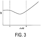
- the relationship between the parameter "n 2 D/ ⁇ (Bd)" and the output BHP required for performing the predetermined same propulsion has characteristics illustrated in FIGS. 2 to 4 . Since the output BHP is an output necessary for performing the same propulsion, a marine vessel having a higher propulsion efficiency can be obtained by performing the same propulsion even when the output BHP is small.
- the propulsion efficiency can be improved by taking a large propeller disk area.
- the parameter "n 2 D/ ⁇ (Bd)" is 4 or more
- the output BHP which is substantially constant when the parameter is less than 4
- the larger the propeller disk ratio does not necessarily improve the propulsion efficiency.
- the output BHP is lower than when the parameter "n 2 D/ ⁇ (Bd)" is less than 5.
- the output BHP is lower than when the parameter "n 2 D/ ⁇ (Bd)" is greater than 15.
- the output BHP is in a narrower range on the low side than when the parameter "n 2 D/ ⁇ (Bd)" is 4 or more and 35 or less. From these results, it can be found that when the parameter "n 2 D/ ⁇ (Bd)" is 5 or more and 15 or less, there is a further effect in reducing the output BHP, and the propulsion efficiency can be further improved.
- the output BHP is lower than when the parameter "n 2 D/ ⁇ (Bd)" is less than 7.
- the output BHP is lower than when the parameter "n 2 D/ ⁇ (Bd)" is greater than 10.
- the output BHP is in a narrower range on the low side than when the parameter "n 2 D/ ⁇ (Bd)" is 5 or more and 15 or less. From these results, it can be found that when the parameter "n 2 D/ ⁇ (Bd)" is 7 or more and 10 or less, there is a further effect in reducing the output BHP, and the propulsion efficiency can be further improved.
- the number of the propeller 12 and the area of the propeller 12 are set such that the parameter "n 2 D/ ⁇ (Bd)" is 4 or more and 35 or less.
- the propulsion efficiency can be improved for the entire operation of the marine vessel 10.
- the number of the propeller 12 and the area of the propeller 12 are set such that the parameter "n 2 D/ ⁇ (Bd)" is 5 or more and 15 or less, it is possible to further improve the propulsion efficiency for the entire operation of the marine vessel 10.
- the number of the propellers 12 and the area of the propeller 12 are set such that the parameter "n 2 D/ ⁇ (Bd)" is 7 or more and 10 or less, it is possible to further improve the propulsion efficiency for the entire operation of the marine vessel 10.
- FIG. 5 illustrates the results of comparing the parameters "n 2 D/ ⁇ (Bd)" between a single-axle ship with one propeller, a two-axle ship with two propellers, a tugboat, and the marine vessel 10 according to the first embodiment.
- the parameter "n 2 D/ ⁇ (Bd)" is less than four.
- the single-axle ship has the lowest parameter " 2 D/ ⁇ (Bd)" of less than 4, the two-axle ship is the next lowest, and the tugboat is the next lowest.
- the parameter "n 2 D/ ⁇ (Bd)" of each of the single-axle ship, the two-axle ship, and the tugboat is less than 4, while the parameter "n 2 D/ ⁇ (Bd)" of the first embodiment is 4 or more and falls within a range of 4 or more and 35 or less.
- the propeller 12 may be a Fixed Pitch Propeller (FPP) or a Controllable Pitch Propeller (CPP). As described above, the propeller 12 constituting the POD type thruster 13 may be used, or a shaft-driven propeller that is driven through a shaft from a motor provided in the hull 11 may be used. The one or more propellers 12 may be driven by a motor located outside the hull 11, such as the POD type thruster 13.
- FPP Fixed Pitch Propeller
- CPP Controllable Pitch Propeller
- the efficiency by the wake can be improved, and by increasing the propeller disk area, the propeller efficiency can be improved.
- the propulsion efficiency can be improved for the entire operation of the marine vessel 10.
- the propulsion efficiency of a marine vessel is determined by: the resistance of the hull, the propeller efficiency, and the mutual influence of the hull and the propeller, and there is a recent trend toward reducing the burden on the global environment, requiring unprecedented high efficiency.
- the regulation of exhaust gas for marine vessels is about to start, and these days, a shift is in progress from a diesel engine using light oil, which has been the mainstream solution, to a gas turbine and a steam turbine using a low-sulfur component fuel such as LNG.
- the propeller 12 is also electrified.
- the marine vessel 10 since a plurality of relatively small propellers 12 are installed on the hull 11, it is suitable for electrifying with a high degree of freedom in the arrangement, the number, the diameter, or the like, of propellers 12.
- the propulsion efficiency can be improved for the entire operation of the marine vessel 10.
- the marine vessel 10 takes advantage of electrification for the entire operation.
- n ⁇ (D/ ⁇ (Bd)) obtained by multiplying a numerical value (which is the product of the propeller disk area, with respect to the hull transverse cross-sectional area under the water surface, and the propeller number) by the propeller number
- n is the number of the propellers 12
- D is the diameter of the propeller 12
- B is the water line breadth of the hull 11
- d is the draft of the hull 11.
- the marine vessel 10 has n ⁇ (D/ ⁇ (Bd)) of 4 or more and 35 or less.
- the marine vessel 10 has n ⁇ (D/ ⁇ (Bd)) of 5 or more and 15 or less. More preferably, the marine vessel 10 has n ⁇ (D/ ⁇ (Bd)) of 7 or more and 10 or less.
- a marine vessel according to a second embodiment of the present disclosure will be described focusing on differences from the first embodiment mainly with reference to FIGS. 6 to 8 .
- the extension lines of the rotation central axes of all the propellers 12 are located within the range of the hull 11 located on a bow side from the positions of the propellers 12, by a length Lx of 12.5% of the length between perpendiculars (Lpp) of the hull 11.
- the rotation central axes of all the propellers 12 overlap, by the length Lx, the shape of the hull 11 located upstream from the installation position of the propeller 12.
- a point X extending from each installation position toward the bow side by the length Lx on the extension line of each rotation central axis line is within the range of the cross section of the hull 11 on a plane including the point X and extending in a vertical direction and the molded breadth direction.
- the propeller 12 has a characteristic that the performance is improved when it is installed in a place where it receives a large wake.
- the wake largely depends on the boundary layer generated in the hull 11, and there is a large correlation between the shape of the hull 11 and the wake distribution.
- FIG. 8 similarly to FIG. 1 , velocity distribution of the wake is indicated by the two-dot chain lines A to E below the ship bottom 15.
- FIG. 8 an example of the shape of the hull 11 located 12.5% of the length between perpendiculars Lpp upstream from the positions of the propellers 12(a) to 12(f) is indicated by a dashed line Y.
- all of the propellers 12(a) to 12(f) are disposed such that the extension lines of the rotation central axes are located within a range of the hull 11 located on the bow side by the length Lx of 12.5% of the length between perpendiculars Lpp of the marine vessel 10, from the respective positions.
- the propulsion efficiency can be further improved for the entire operation of the marine vessel 10.
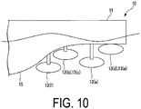
- a marine vessel according to a third embodiment of the present disclosure will be described focusing on differences from the first and second embodiments mainly with reference to FIGS. 9 and 10 .
- the third embodiment is changed from the first and second embodiments in that the plurality of propellers 12 are shifted in position in the front-back direction of the hull 11.
- each of the plurality of propellers 12 constitutes POD type thruster 13 of a hub drive type that drives the hub side of the propeller 12.
- a plurality of the POD type thrusters 13(a) to 13(f) each having the propeller 12 are arranged so as to be shifted in the front-back direction of the hull 11.
- the POD type thruster 13(f) is disposed on the most bow side
- the POD type thrusters 13(b) and 13(c) are disposed on the stern side of the POD type thruster 13(f)
- the POD type thruster 13(a) is disposed on the stern side of the POD type thrusters 13(b) and 13(c)
- the POD type thrusters 13(d) and 13(e) are disposed on the stern side of the POD type thruster 13(a).
- the plurality of propellers 12(a) to 12(f) are disposed so as to be shifted in position in the front-back direction of the hull 11 so as to improve efficiency under wake from the hull 11.
- the plurality of propellers 12 are shifted in position in the front-back direction of the hull 11, the plurality of propellers 12 can be efficiently disposed at locations where the wake from the hull 11 is large, and the influence of mutual interference between the propellers 12 can be eliminated or effectively used.
- a marine vessel according to a fourth embodiment of the present disclosure will be described focusing on differences from the first to third embodiments mainly with reference to FIGS. 11 and 12 .
- a fourth embodiment is different from the third embodiment in that the plurality of propellers 12 partially overlap each other in at least one of the molded breadth direction and the vertical direction of the hull 11.
- the plurality of propellers 12 are disposed so as to overlap each other in at least one of the molded breadth direction and the vertical direction of the hull 11.
- propellers 12 are provided symmetrically in the molded breadth direction, and three propellers 12 are provided at the center in the molded breadth direction on the hull 11 side and on both sides thereof. That is, the propeller 12(a) is provided at the center in the molded breadth direction on the hull 11 side, and the propellers 12(b) and 12(c) are provided on both sides of the propeller 12(a) on the hull 11 side.
- the three propellers 12(a) to 12(c) have substantially the same distance from the ship bottom 15.
- one propeller 12(d) is provided vertically below the propeller 12(a) at the center in the molded breadth direction.
- the three propellers 12(a) to 12(c) on the hull 11 side overlap each other in the vertical direction.
- the propeller 12(a) at the center in the molded breadth direction overlaps in the molded breadth direction the propeller 12(b) adjacent thereto on one side in the molded breadth direction and also overlaps in the molded breadth direction the propeller 12(c) adjacent thereto on the other side in the molded breadth direction.
- the propellers 12(b) and 12(c) on both outer sides in the molded breadth direction do not overlap each other in the molded breadth direction, but overlap each other only in the vertical direction.
- the propeller 12(a) at the center in the molded breadth direction on the hull 11 side and the propeller 12(d) vertically below the propeller 12(a) overlap in both the molded breadth direction and the vertical direction.
- the propeller 12(a) on the hull 11 side and at the center in the molded breadth direction and the propeller 12(d) vertically below the propeller 12(a) appear to overlap when viewed along the direction of their rotation central axes.
- the propeller 12(d) on the lower side of the center in the molded breadth direction overlaps the propellers 12(b) and 12(c) (which are located on the hull 11 side and on both outer sides in the molded breadth direction) in both the molded breadth direction and the vertical direction, but does not appear to overlap each other even when viewed along the direction of these rotation central axes.
- each of the plurality of propellers 12 constitutes the POD type thruster 13. That is, the propeller 12(a) constitutes the POD type thruster 13(a), the propeller 12(b) constitutes the POD type thruster 13(b), the propeller 12(c) constitutes the POD type thruster 13(c), and the propeller 12(d) constitutes the POD type thruster 13(d).
- the plurality of POD type thrusters 13(a) to 13(d) each having the propeller 12 partially overlap in at least one of the molded breadth direction and the vertical direction. As illustrated in FIG.
- the POD thrusters 13(a) to 13(d) are disposed such that the POD type thruster 13(a) is disposed on the most bow side, the POD type thrusters 13(b) and 13(c) are disposed on the stern side of the POD type thruster 13(a), and the POD type thruster 13(d) is disposed on the stern side of the POD type thrusters 13(b) and 13(c).
- the plurality of propellers 12(a) to 12(d) illustrated in FIG. 11 are also shifted in position in the front-back direction of the hull 11 in the same manner as the POD type thrusters 13(a) to 13(d).
- the plurality of propellers 12 are displaced in the front-back direction of the hull 11 and are overlapped in at least one of the molded breadth direction and the vertical direction of the hull 11, so that the plurality of propellers 12 can be efficiently disposed in a place where the wake from the hull 11 is large, and one propeller 12 disposed behind another propeller recovers the swirl flow generated from the other propeller 12 to function as a Contra Rotating Propeller (CRP), thereby achieving high efficiency.
- CRP Contra Rotating Propeller
- a marine vessel according to a fifth embodiment of the present disclosure will be described focusing on differences from the first to fourth embodiments mainly with reference to FIG. 13 .
- the fifth embodiment is changed from the first to fourth embodiments in that the plurality of propellers include: a shaft-driven propeller 21 driven by an electric motor provided in the hull 11 through a shaft; and a propeller 12 (not illustrated in FIG. 13 ) constituting the POD type thruster 13.
- the plurality of propellers are a combination of the shaft-driven propeller 21 and the propeller 12 (not illustrated in FIG. 13 ) of the POD type thrusters 13.
- the shaft-driven propeller 21 is provided instead of one of the POD type thrusters 13 of the fourth embodiment.
- the shaft-driven propeller 21 is provided instead of the propeller 12 of the POD type thruster 13 on the lower side of the center in the molded breadth direction. Therefore, the plurality of POD type thrusters 13 are provided on the hull 11 side, and the shaft-driven propeller 21 is provided below the POD type thrusters 13.
- the propeller 12 (not illustrated in FIG. 13 ) of the POD type thruster 13 includes a drive unit such as a motor extending to the outside of the hull 11, which causes to increase the ship resistance.
- a drive unit such as a motor extending to the outside of the hull 11, which causes to increase the ship resistance.
- the marine vessel 10 of the fifth embodiment by using the shaft-driven propeller 21 and the POD type thruster 13 in combination, it is possible to design the marine vessel in consideration of a balance between an increase in resistance and an increase in propeller efficiency. For example, it is possible to suppress an increase in resistance by using the shaft-driven propeller 21 for a portion where a shaft can be extended from the hull 11 and by using the POD type thruster 13 only for a portion where it is difficult to extend the shaft. Therefore, since an increase in resistance due to the POD type thruster 13 can be suppressed, the propulsion performance can be improved.
- a marine vessel according to a sixth embodiment of the present disclosure will be mainly described focusing on differences from the first to fifth embodiments.
- the sixth embodiment is different from the first to fifth embodiments in that one or more of the plurality of POD type thrusters 13 includes an azimuth mechanism rotatable about a strut extending from the hull 11.
- at least one of the plurality of propellers 12 constitutes the POD type thruster 13 including the azimuth mechanism.
- at least one of the plurality of POD type thrusters 13 may each include a rotatable azimuth mechanism.
- the turning performance can be improved by providing the azimuth mechanism in each of one or more POD type thrusters 13. For example, when this makes a rudder unnecessary, the hull resistance will decrease, and it is possible to aim for further improvement in propulsion performance. In addition, it is possible to obtain great merits even when maneuvering in a port.
- a marine vessel according to a seventh embodiment of the present disclosure will be described focusing on differences from the first to sixth embodiments mainly with reference to FIG. 14 .
- one or more of the plurality of POD type thrusters 13 are inclined in the vertical direction so as to be positioned higher toward the stern side.
- the propeller 12 (not illustrated in FIG. 14 ) of the inclined POD type thruster 13 is also inclined in the vertical direction so that the rotation central axis thereof is positioned higher toward the stern side.
- a single POD type thruster 13 is extracted from the plurality of POD type thrusters 13.
- the POD type thruster 13 is inclined so as to be positioned higher toward the stern side along the shape of the hull 11.
- the POD type thruster 13 is inclined along the roll-up flow in accordance with the roll-up flow from the hull 11. Since the POD type thruster 13 is inclined in this manner, the rotation central axis of the propeller 12 (not illustrated in FIG. 14 ) is also inclined so as to be positioned higher toward the stern side so as to follow the shape of the hull 11 and is inclined so as to follow the roll-up flow in accordance with the roll-up flow from the hull 11.
- one or more POD type thrusters 13 are provided so as to be inclined such that the rotation central axis of the propeller 12 is positioned higher toward the stern side.
- the rotation central axis of the propeller 12 can be aligned with the roll-up flow from the hull 11, thereby improving propeller efficiency.
- the frictional resistance of the ship bottom can be reduced.
- a marine vessel according to an eighth embodiment of the present disclosure will be described focusing on differences from the first to seventh embodiments.
- the plurality of propellers 12 are configured such that the number of the propellers to be driven is changed according to the operation mode. For example, several propellers 12 are stopped in a light load state, or several propellers 12 are stopped during low-speed operation such as in a port.
- the main engine output can be optimized in accordance with the operation mode.
- POD type thruster 13 of a hub drive type for driving the hub side which is the rotation central side of the propeller 12
- POD type thruster of a rim drive type that drives a rim side, which is the outer peripheral side of the propeller.
- the marine vessel 10 according to each embodiment of the present disclosure is grasped as follows, for example.
Landscapes
- Chemical & Material Sciences (AREA)
- Engineering & Computer Science (AREA)
- Combustion & Propulsion (AREA)
- Mechanical Engineering (AREA)
- Ocean & Marine Engineering (AREA)
- Structures Of Non-Positive Displacement Pumps (AREA)
- Other Liquid Machine Or Engine Such As Wave Power Use (AREA)
Applications Claiming Priority (1)
| Application Number | Priority Date | Filing Date | Title |
|---|---|---|---|
| JP2020005891A JP7326172B2 (ja) | 2020-01-17 | 2020-01-17 | 船舶 |
Publications (1)
| Publication Number | Publication Date |
|---|---|
| EP3851369A1 true EP3851369A1 (de) | 2021-07-21 |
Family
ID=74103952
Family Applications (1)
| Application Number | Title | Priority Date | Filing Date |
|---|---|---|---|
| EP21150213.3A Withdrawn EP3851369A1 (de) | 2020-01-17 | 2021-01-05 | Seeschiff |
Country Status (4)
| Country | Link |
|---|---|
| US (1) | US11591056B2 (de) |
| EP (1) | EP3851369A1 (de) |
| JP (1) | JP7326172B2 (de) |
| CN (1) | CN113135278A (de) |
Citations (8)
| Publication number | Priority date | Publication date | Assignee | Title |
|---|---|---|---|---|
| JPS6295999A (ja) | 1985-10-22 | 1987-05-02 | Fuji Electric Co Ltd | ステツピングモ−タの停止制御方法 |
| JP2005526665A (ja) | 2002-05-24 | 2005-09-08 | ワルトシラ フィンランド オサケユキチュア | 海洋船舶推進構造及びその動作方法 |
| JP2007022447A (ja) | 2005-07-20 | 2007-02-01 | Oshima Shipbuilding Co Ltd | 2軸船 |
| JP2010195382A (ja) * | 2009-01-27 | 2010-09-09 | Osaka Prefecture Univ | 上下可動式推進装置を備えた船舶 |
| WO2010140357A1 (ja) * | 2009-06-06 | 2010-12-09 | 独立行政法人海上技術安全研究所 | 二軸船尾双胴型船舶 |
| WO2013119175A1 (en) * | 2012-02-07 | 2013-08-15 | Rolls-Royce Ab | A propulsor arrangement for a marine vessel and a marine vessel constructed with this type of propulsor arrangement |
| WO2014123465A1 (en) * | 2013-02-11 | 2014-08-14 | Stena Rederi Ab | Ship |
| EP2821334A2 (de) * | 2009-11-05 | 2015-01-07 | Mitsubishi Heavy Industries, Ltd. | Verstärkungsstruktur für ein Schiff |
Family Cites Families (14)
| Publication number | Priority date | Publication date | Assignee | Title |
|---|---|---|---|---|
| FR389330A (fr) * | 1907-03-04 | 1908-09-05 | Guido Gianoli | Moteur à gaz pauvre spécialement applicable à la navigation |
| JPS5015341Y1 (de) * | 1970-12-30 | 1975-05-13 | ||
| JPS6295999U (de) * | 1985-12-09 | 1987-06-18 | ||
| JPH09142391A (ja) | 1995-11-22 | 1997-06-03 | Mitsubishi Heavy Ind Ltd | 旋回式プロペラ付き船舶 |
| FI113753B (fi) * | 2002-02-06 | 2004-06-15 | Kvaerner Masa Yards Oy | Järjestelmä, menetelmä ja asennusmenetelmä vesikulkuneuvossa |
| FI121659B (fi) * | 2004-11-29 | 2011-02-28 | Waertsilae Finland Oy | Vesialuksen propulsiojärjestelmä |
| CN101137538B (zh) * | 2005-03-11 | 2011-01-12 | 株式会社川崎造船 | 船舶的船尾结构 |
| JP4934361B2 (ja) * | 2006-07-06 | 2012-05-16 | 三井造船株式会社 | 船舶 |
| JP2011235740A (ja) * | 2010-05-10 | 2011-11-24 | Kayseven Co Ltd | 船舶 |
| CN102530188A (zh) * | 2011-12-06 | 2012-07-04 | 武汉武船海洋工程船舶设计有限公司 | 一种内河旅游船 |
| JP5857327B2 (ja) * | 2011-12-30 | 2016-02-10 | ニッコー・エンターテインメント・ホンコン・リミテッド | ラジコンボートにおける推進及び方向転換装置 |
| NL2009156C2 (nl) * | 2012-07-09 | 2014-01-13 | Imc Corporate Licensing B V | Vaartuig met roteerbare pod. |
| CN202827987U (zh) * | 2012-10-12 | 2013-03-27 | 中国船舶重工集团公司第七○二研究所 | 垂直首柱运输船型 |
| EP3105115A1 (de) * | 2014-02-13 | 2016-12-21 | Rolls-Royce Marine AS | Verbesserungen im zusammenhang mit einem schiffsantrieb mit primären und sekundären antriebsvorrichtungen |
-
2020
- 2020-01-17 JP JP2020005891A patent/JP7326172B2/ja active Active
- 2020-12-30 US US17/137,604 patent/US11591056B2/en active Active
- 2020-12-30 CN CN202011622169.2A patent/CN113135278A/zh active Pending
-
2021
- 2021-01-05 EP EP21150213.3A patent/EP3851369A1/de not_active Withdrawn
Patent Citations (8)
| Publication number | Priority date | Publication date | Assignee | Title |
|---|---|---|---|---|
| JPS6295999A (ja) | 1985-10-22 | 1987-05-02 | Fuji Electric Co Ltd | ステツピングモ−タの停止制御方法 |
| JP2005526665A (ja) | 2002-05-24 | 2005-09-08 | ワルトシラ フィンランド オサケユキチュア | 海洋船舶推進構造及びその動作方法 |
| JP2007022447A (ja) | 2005-07-20 | 2007-02-01 | Oshima Shipbuilding Co Ltd | 2軸船 |
| JP2010195382A (ja) * | 2009-01-27 | 2010-09-09 | Osaka Prefecture Univ | 上下可動式推進装置を備えた船舶 |
| WO2010140357A1 (ja) * | 2009-06-06 | 2010-12-09 | 独立行政法人海上技術安全研究所 | 二軸船尾双胴型船舶 |
| EP2821334A2 (de) * | 2009-11-05 | 2015-01-07 | Mitsubishi Heavy Industries, Ltd. | Verstärkungsstruktur für ein Schiff |
| WO2013119175A1 (en) * | 2012-02-07 | 2013-08-15 | Rolls-Royce Ab | A propulsor arrangement for a marine vessel and a marine vessel constructed with this type of propulsor arrangement |
| WO2014123465A1 (en) * | 2013-02-11 | 2014-08-14 | Stena Rederi Ab | Ship |
Also Published As
| Publication number | Publication date |
|---|---|
| JP2021112956A (ja) | 2021-08-05 |
| US20210221489A1 (en) | 2021-07-22 |
| US11591056B2 (en) | 2023-02-28 |
| JP7326172B2 (ja) | 2023-08-15 |
| CN113135278A (zh) | 2021-07-20 |
Similar Documents
| Publication | Publication Date | Title |
|---|---|---|
| US5632658A (en) | Tractor podded propulsor for surface ships | |
| KR102033030B1 (ko) | 풍력추진 기능이 구비된 선박 | |
| CN101934854B (zh) | 船 | |
| CA2948468C (en) | Propulsion unit | |
| US20150068439A1 (en) | Device for propelling and turning hull | |
| US8403716B2 (en) | Twin-skeg ship | |
| JP2011025918A (ja) | 船舶用ノズルプロペラ | |
| KR20150006846A (ko) | 노즐의 출구에서 만곡된 후미 가장자리를 갖는 노즐을 포함하는 해양 선박용 추진 유닛 | |
| KR20190076907A (ko) | 해양 선박 | |
| KR102535808B1 (ko) | 풍력 추진 시스템 및 이를 포함하는 선박 | |
| EP3851369A1 (de) | Seeschiff | |
| SG183162A1 (en) | Thruster with duct and ship including the same | |
| KR101225175B1 (ko) | 추진장치 및 이를 포함하는 선박 | |
| CN87105327A (zh) | 船舶 | |
| Gougoulidis et al. | An overview of hydrodynamic energy efficiency improvement measures | |
| US7537500B2 (en) | Ship driven by inboard engines and water jets | |
| Rains et al. | Hydrodynamics of podded ship propulsion | |
| JP7766524B2 (ja) | 船舶 | |
| KR20160149877A (ko) | 선박용 추진 장치 | |
| Van Beek | Technology guidelines for efficient design and operation of ship propulsors | |
| JP7554786B2 (ja) | 推進性能向上装置 | |
| JP2025030351A (ja) | 船舶システム、船舶、及び回転体 | |
| JPH053434Y2 (de) | ||
| Pavlov et al. | ALS and ACC Propulsion | |
| CN101962071B (zh) | 船舶的喷嘴螺旋桨 |
Legal Events
| Date | Code | Title | Description |
|---|---|---|---|
| PUAI | Public reference made under article 153(3) epc to a published international application that has entered the european phase |
Free format text: ORIGINAL CODE: 0009012 |
|
| STAA | Information on the status of an ep patent application or granted ep patent |
Free format text: STATUS: THE APPLICATION HAS BEEN PUBLISHED |
|
| AK | Designated contracting states |
Kind code of ref document: A1 Designated state(s): AL AT BE BG CH CY CZ DE DK EE ES FI FR GB GR HR HU IE IS IT LI LT LU LV MC MK MT NL NO PL PT RO RS SE SI SK SM TR |
|
| STAA | Information on the status of an ep patent application or granted ep patent |
Free format text: STATUS: REQUEST FOR EXAMINATION WAS MADE |
|
| 17P | Request for examination filed |
Effective date: 20220110 |
|
| RBV | Designated contracting states (corrected) |
Designated state(s): AL AT BE BG CH CY CZ DE DK EE ES FI FR GB GR HR HU IE IS IT LI LT LU LV MC MK MT NL NO PL PT RO RS SE SI SK SM TR |
|
| STAA | Information on the status of an ep patent application or granted ep patent |
Free format text: STATUS: THE APPLICATION HAS BEEN WITHDRAWN |
|
| 18W | Application withdrawn |
Effective date: 20230428 |