EP3851604A1 - Élément lumineux et procédé de fabrication de l'élément lumineux - Google Patents
Élément lumineux et procédé de fabrication de l'élément lumineux Download PDFInfo
- Publication number
- EP3851604A1 EP3851604A1 EP20217495.9A EP20217495A EP3851604A1 EP 3851604 A1 EP3851604 A1 EP 3851604A1 EP 20217495 A EP20217495 A EP 20217495A EP 3851604 A1 EP3851604 A1 EP 3851604A1
- Authority
- EP
- European Patent Office
- Prior art keywords
- sealing tape
- light element
- plates
- elastic sealing
- textile
- Prior art date
- Legal status (The legal status is an assumption and is not a legal conclusion. Google has not performed a legal analysis and makes no representation as to the accuracy of the status listed.)
- Granted
Links
Images


Classifications
-
- E—FIXED CONSTRUCTIONS
- E04—BUILDING
- E04C—STRUCTURAL ELEMENTS; BUILDING MATERIALS
- E04C2/00—Building elements of relatively thin form for the construction of parts of buildings, e.g. sheet materials, slabs, or panels
- E04C2/02—Building elements of relatively thin form for the construction of parts of buildings, e.g. sheet materials, slabs, or panels characterised by specified materials
- E04C2/10—Building elements of relatively thin form for the construction of parts of buildings, e.g. sheet materials, slabs, or panels characterised by specified materials of wood, fibres, chips, vegetable stems, or the like; of plastics; of foamed products
- E04C2/24—Building elements of relatively thin form for the construction of parts of buildings, e.g. sheet materials, slabs, or panels characterised by specified materials of wood, fibres, chips, vegetable stems, or the like; of plastics; of foamed products laminated and composed of materials covered by two or more of groups E04C2/12, E04C2/16, E04C2/20
-
- E—FIXED CONSTRUCTIONS
- E04—BUILDING
- E04C—STRUCTURAL ELEMENTS; BUILDING MATERIALS
- E04C1/00—Building elements of block or other shape for the construction of parts of buildings
- E04C1/42—Building elements of block or other shape for the construction of parts of buildings of glass or other transparent material
-
- E—FIXED CONSTRUCTIONS
- E04—BUILDING
- E04C—STRUCTURAL ELEMENTS; BUILDING MATERIALS
- E04C2/00—Building elements of relatively thin form for the construction of parts of buildings, e.g. sheet materials, slabs, or panels
- E04C2/54—Slab-like translucent elements
- E04C2/543—Hollow multi-walled panels with integrated webs
Definitions
- the invention relates to a light element with at least two translucent plates, between which there is a flat textile, and a method for producing this light element.
- Such light elements with plates made of transparent plastic material are required and used to a large extent in or on the roofs of e.g. factory halls, factory buildings and also office buildings for lighting.
- lighting elements can be provided not only on roofs, but also, for example, on the walls of a building or on free-standing supports.
- Translucent sheets are usually designed as hollow-chamber elements, such as extruded multi-wall sheets, e.g. double-walled sheets.
- the lighting in interiors should be glare-limited according to DIN 5034. It is therefore known to use opalized plastic for the translucent plates, which, however, entails an undesirable loss of light. Since, in accordance with DIN 4102, Part 7, elements of skylight structures must be prevented from falling down in the event of a fire, the EP 1332 261 B1 the use of a fabric-like material between two double-walled panels combined in a sandwich construction is proposed.
- the fabric-like material is in the EP 1332 261 B1 loosely placed between the double wall sheets so that it is independent of changes in length of the double wall sheets, for example due to thermal expansion. Damage to the fabric-like material due to tensile stress can thus be avoided.
- a rigid spacer is provided between the double wall plates.
- the inserted tissue-like material then has a small distance of, for example, 0.5 to 2 mm from the double-walled panels and can move freely in the cavity thus formed between the upper and lower panels. If the panels of the light element expand as a result of the action of heat, the commercial material is not affected by it, it will neither clamped at its edges nor at any other point of the plates, so that no tensile stresses arise in the fabric-like material.
- the object of the invention is therefore to provide a light element and a method for its production which is easy to produce and to ensure tightness over the service life of the light element.
- an elastic sealing band is provided which is arranged along edges of the panels of the light element between these panels.
- the distance between the at least two plates of the light element is adjusted by the elastic sealing tape arranged between these plates.
- a sheet-like textile arranged between the respective plates is thinner than the spacing between the plates.
- the elasticity of the sealing tape is chosen so that at least the weight of the plates arranged above it when the light element is arranged horizontally only causes compression of the sealing tape, which leads to a distance between the two plates that is greater than the thickness of the sheet-like textile .
- a light element can be achieved with simple means that provides a cavity for jamming-free accommodation of the sheet-like textile through a spacing function of the sealing tape, the sealing tape at the same time being able to seal the cavity created between the plates.
- an elastic sealing tape can be used as a sealing spacer and, in particular, the separate use of spacers with additional sealing means can be avoided. Due to the elasticity or elastic deformability of the sealing tape, it is possible to deform it in a defined manner in order to ensure a sealing function or to improve it compared to the solutions known from the prior art, while the sealing tape is adjustable to a defined thickness, whereby a defined height of the cavity can be achieved.
- the light element according to the invention has a simplified structure, reduced production effort and thus production costs and improves the manageability of the light element, since an elastic spacer that seals itself is used.
- one side of the elastic sealing tape is at least partially adhesively connected to one of the plates.
- the sealing tape can thus be placed on the body and is thus fixed in a fixed relative position with respect to this plate. This improves the operability.
- the sealing effect of the sealing tape can be improved by gluing.
- the adhesive can counteract a recovery of the sealing tape. The forces required to maintain the elastic deformation of the sealing tape can therefore be reduced.
- a double-sided adhesive elastic sealing tape is used, that is to say two sides of the elastic sealing tape are at least partially adhesively connected to both plates.
- double-sided bonding it is possible with double-sided bonding to seal the light element particularly well and durably, for example on one end face, so that the penetration can be reliably prevented even if there is backwater when it rains.
- gluing on both sides improves handling up to the final assembly of the light element.
- the panels are fixed relative to one another by gluing the sealing tape and the panels are prevented from shifting in relation to one another, for example during transport to the construction site and during assembly.
- the entire elastic sealing tape which is arranged between 2 adjacent plates of the light element, comprises a plurality of sealing tape sections, which are arranged between the plates, wherein between the several Joints resulting from sealing tape sections are sealingly joined, in particular glued.
- This makes it possible to assemble the sealing tape from piecewise applied endless goods or piece goods and thus to use commercially available or standard goods. This lowers the costs, while virtually any shape of the sealing tape can be achieved with a minimum of variety of goods.
- straight sealing tape sections can be provided at an angle to one another, so that a, for example, rectangular sealing tape can be achieved.
- an adhesive tape is arranged around the edge of the at least two panels arranged on top of one another, so that the sealing tape arranged between these panels remains compressed until the elements are installed.
- the sealing effect is improved by compressing the sealing tape.
- the tendency of the sheet-like textile to fold in folds can be reduced by the height of the cavity being reduced in this way, which improves the manageability of the light element.
- a protective film such as a hail protection film, can be attached to an outside of the light element by means of the adhesive tape.
- the sealing tape By using the adhesive tape, that is to say a flexible means, to produce a sealing tape compression, the sealing tape can be compressed to a final distance dimension by a further clamping device for assembly without the adhesive tape having to be removed beforehand. A sufficient sealing effect is thus guaranteed at all times. If the sealing tape is compressed by attaching the adhesive tape directly after the production of the light element, the light element can also be handled in any position without the panels slipping.
- the adhesive tape also serves as a transport and positional security device.
- the light element consists of only 2 panels. What has been said applies analogously to the case that the light element comprises more than 2 plates.
- FIGS 1a and 1b show the first embodiment of the invention in a cross section.
- the light element 10 according to the invention of this exemplary embodiment comprises double-walled sheets 1, 2 as examples of translucent sheets 1, 2.
- the sheets 1, 2 can be made, for example, of polycarbonate, PVC, PMMA, PET, glass or other materials. Polycarbonate is particularly preferably used because it has good mechanical properties, such as high strength and impact strength.
- bodies of any desired shape, such as sheets or domes can of course be used; For example, simple multi-skin sheets, solid sheets or multi-wall sheets, but also thermal glasses.
- the number of plates 1, 2 arranged next to or one above the other is also not limited, but rather dependent on the intended use, plate shape, and the like, and can be essentially any.
- a spacing elastic sealing tape 4 creates a cavity H.
- a flat textile 3 is arranged. Apart from securing against falling parts in the event of a fire, this is used in a known manner to, from the outside, in Fig. 1 from above, to change incident light, e.g. to scatter it, so that the in Fig. 1 light emitted on the lower side can be emitted glare-free or at least glare-limited. Incident infrared radiation can also be reduced.
- a large number of sheet-like textiles 3 are suitable for this purpose.
- Nonwovens and preferably woven fabrics for example made from glass fibers, have proven to be particularly suitable. In addition to good optical properties, these also have advantageous heat resistance, so that fire safety of the light element 10 can be ensured.
- the sheet-like textile 3 is or is inserted into the cavity H.
- the height of the cavity when the light element is not yet installed is 50% to 100% greater than the thickness of the elastic sealing tape 4 to be described. This allows further compression of the elastic sealing tape 4 when the light element is installed on the building.
- the elastic sealing tape 4 is provided as an essentially solid mass, in contrast to sealing means which are applied in liquid or pasty form. This makes it possible, in a manner to be described in more detail, to elastically deform or compress the sealing tape 4 and thus to build up a sealing surface pressure when the plates 1, 2 and, by means of this, the sealing tape 4 are subjected to compressive force.
- the light element with a correspondingly compressed by means of an adhesive tape 5 Sealing tape 4 is in Figure 1b shown.
- a force is generated for this purpose, which moves the two plates towards one another.
- the sealing tape is thus elastically deformed.
- the adhesive tape is applied in such a way that it encompasses the edges of both panels 1, 2.
- the mechanical strength of the adhesive tape prevents, after the plates 1, 2 have been loosened, the elastic sealing tape from relaxing beyond an amount predetermined by the adhesive tape.
- the sealing tape 4 is, as in Fig. 2 shown by way of example, on the lower plate 1 along its edges R completely circumferential. In other words, the sealing tape 4 has no gaps.
- a sealing tape 4 that is prefabricated and configured in the desired shape can be used, which reduces the outlay on assembly.
- the required shape for producing the sealing tape 4 is punched out of a flat light element, for example.
- the sealing tape 4 can alternatively be composed of individual sealing tape elements (sealing tape sections), as in FIG Figures 3a-c made clear. In this, joints of the sealing tape sections 4.1 and 4.2, which are designed to be geometrically different, are shown schematically as dashed lines.
- the joints are joined without gaps, preferably by gluing.
- welding the joint ends can also be advantageous, since this enables shorter processing cycle times and faster further processing.
- Gluing in turn, is simple and can be carried out with few resources.
- the glued or welded joint has sufficient tensile strength in the sealing tape plane, i.e. sufficient loading capacity when the sealing tape 4 is stretched transversely, so that it is compressed and thus deformed in the sealing tape 4 the joint does not come off or tear.
- This can be achieved, for example, through a suitable choice of adhesive, a large amount of adhesive or even welding. It is preferred to choose the cold seam strength at least as high as the tensile strength of the sealing tape material.
- the sealing tape 4 must be elastic so that it can be compressed in a defined manner and has a sealing effect.
- (rubber) elastic materials in particular have proven to be advantageous.
- a foam or cellular soft plastic is particularly preferably used.
- the porosity of the material is sufficiently small to prevent water from creeping along an interface between the double-walled sheet 1, 2 and sealing tape 4, as well as preventing water from being sucked into the material.
- an elastomer such as a (synthetic) rubber known per se, meets these requirements.
- the sealing tape 4 is used in the in Fig. 1a
- the horizontal light element 10 shown is loaded by a weight of the upper plate 2 (in the case of more than 2 plates, by all of the plates arranged above).
- the sealing tape 4 is deformed according to its elastic deformability; so compressed by the acting pressure force in the thickness or height direction, which leads to an expansion in the transverse direction or in the plane.
- the sheet-like textile 3 should have the possibility of deforming independently of the plates 1, 2 (for example through thermal expansion), or of not having any force-locking contact with the plates 1, 2.
- the sealing tape 4 must have such a low elasticity or so low elastic deformability that it is deformed by the load with the weight of the upper plate 2 to such an extent that the distance between the plates 1, 2 ensured by the sealing tape 4 is greater than the thickness of the fabric 3.
- the sealing tape 4 must have such a high elastic deformability that it can be compressed with such little force to the desired thickness, which can be applied and held by an adhesive tape 5 or a clamping device 20 without damaging the light element 10 .
- the thickness of the sealing tape 4 when compressed to 50 ... 67% of its original thickness or height is almost the same as that of the sheet-like textile 3. Tests have shown that the sealing tape is compressed to about 50 ... 67% of its thickness that the sealing effect of the sealing tape is optimal in many cases.
- other compression values are also suitable, depending on the material of the sealing tape.
- sealing tape 4 is arranged only on the edges of two plates 1, 2 arranged parallel to one another.
- further sealing tape sections can be provided to subdivide the entire surface.
- the relevant embodiment, in which webs are provided in the interior of the sealing tape 4 surrounding the plate, are also conceivable. Such webs are to be provided in particular if a screw connection has to be provided for fixing the light element in the interior of the surface.
- the elastic sealing tape 4 is placed with its underside on the upward-facing surface of the lower plate 1.
- the sealing tape 4 can be partially or completely glued to the plate on one side, for example in the area in which backwater is to be expected with an inclined installation in a U-shaped rail or in which backwater is to be expected due to a particularly exposed location.
- the sealing effect can be further increased by this bonding. It is thereby also possible to fix the sealing tape 4 on the lower plate 1 so that it holds a certain position by no longer slipping. It should be noted that when using a plate 1, 2 made of polycarbonate, an appropriately compatible adhesive must be used.
- gluing is also understood to mean any other suitable form of adhesive connection.
- the surface of the sealing tape 4 can also be activated thermally or chemically, e.g. melted or loosened, in order to achieve an adhesive connection with a plate 1, 2.
- Pretreatments of the plate 1, 2 and / or the sealing tape 4 are also conceivable, which increase the wettability, e.g. by means of plasma treatment or corona treatment.
- the sealing band 4 of the light element 10 is preferably provided at a distance on all sides from the edges R of the plates 1, 2, as in FIG Fig. 1a shown, so that the sealing tape 4, which is deformable by compression, does not protrude beyond the edge of the double-walled plate 3 when it extends transversely. Damage to the sealing tape 4 when handling the light element 10 can thus be avoided.
- a lateral protective device is preferably provided to protect the sealing tape 4; this can be formed, for example, by the adhesive tape 5.
- the fabric 3 is placed in an area F delimited by the sealing tape 4 on the lower double-walled plate 1, the area F corresponding to the cavity H of the finished light element 10.
- the fabric 3 is preferably dimensioned such that it takes up a distance of 0.5 to 2 mm on all sides from the sealing tape 4 so that the fabric 3 is not pinched by compression when the sealing tape 4 expands transversely. If, however, a sealing tape 4 is used, the material of which has a small transverse extent, the fabric 3 can also be provided flush with the sealing tape 4 for optimal coverage of the surface F.
- the optical properties of the textile 3 can be guaranteed uniformly over the entire surface F in both cases.
- the fixing of the textile 3 takes place in a known manner as in the case of a light element, the plates 1, 2 of which are connected by means of rigid spacers.
- the top plate 2 is placed on the sealing tape 4.
- an at least partially adhesive connection can be advantageous here.
- the upper plate 2 is preferably arranged flush with the lower one. However, should, for example, a Saddle construction are made possible, a parallel alignment of side surfaces of the plates 1 is sufficient.
- the adhesive tape 5 is attached to the side areas of the plates 1, 2. This is attached to the plates 1, 2 under prestress in such a way that the sealing tape 4 is compressed to the second thickness.
- the adhesive tape 5 is shown schematically in FIG Figure 1b shown.
- the adhesive tape 5 is first attached to an outside of the upper plate 2, the light element 10 is pre-compressed to the desired size by means of a press, manually or by pulling the partially attached adhesive tape 5 and finally attached to the lower plate 1 in this state.
- the adhesive tape 5 is preferably an aluminum adhesive tape 5 with sufficient tensile strength. If a press is used to apply the adhesive tape 5, which presses the two plates 1, 2 against one another, the adhesive tape 5 can of course also be fastened to the lower plate 1 first.
- the adhesive tape 5 By increasing the compression by means of the adhesive tape 5, preferably immediately after the production of the light element, it can be ensured that the plates 1, 2 are kept secured against slipping even without the use of adhesive between the sealing tape 4 and the plates 1, 2. As explained, the sealing function of the sealing tape 4 is increased by the compression. If adhesive is applied between the sealing tape 4 and the plates 1, 2, this securing by the adhesive tape 5 means that the adhesive layer can harden or develop adhesive strength in a defined relative position of the plates 1, 2 to one another.
- a hail or transport protection film can also be attached to the outer sides of the plates 1, 2 and fixed by means of the adhesive tape 5. This saves additional, separate fastening means for attaching such an optional protective film.
- the adhesive tape 5 serves to protect the side areas of the light element 10 against external influences during transport, handling and storage, since the particularly sensitive edges of the light element 10 are shielded from impacts or sharp objects, for example. Damage to the light element 10 can thus be effectively prevented.
- the transportable light element 10 produced in this way can now be handled and stored in any position.
- the cavity H, in which the fabric (textile) 3 is located has been made smaller by the compression in the vertical or normal direction.
- the sealing tape 4 is reduced to the second thickness by means of this compression, which almost corresponds to that of the fabric 3, that is to say is only insignificantly greater. This can also effectively prevent the fabric 3 from slipping due to a change in the position of the light element 10, since it has no possibility of wrinkling or creasing due to the spatial restriction.
- a third distance to be finally set can be provided between the two plates 1, 2, but this is only achieved during final assembly, in which the fastening to the building causes further compression of the elastic sealing tape 4 and which is described below.
- the light element 10 according to the invention for example as a simple light band, can be mounted in a known manner.
- a clamping device 20 arranged on the building side is provided for this purpose, as in FIG Fig. 4 shown.
- This building-side clamping device 20 shown greatly simplified, consists, for example, of a rail 23 or frame, which is arranged on a substrate 21, such as a building roof, and is fixed thereon or on it.
- the rail 23 comprises a bar 24 with threads.
- the light element 10 can be placed on the rail 23 and fixed in the bar 24 by means of one or more screws 22.
- the light element 10 can be screwed through on external sealing strips 4; however, it is also conceivable to provide a sealing tape 4 located further inside and to screw this through, as in FIG Fig. 4 made clear.
- Light elements 10 with a plurality of cavities H subdivided by sealing strips 4 can be particularly useful when large distances are to be bridged and the subdivision is intended to increase the flexural strength of the light strip 10.
- the screw 22 is passed through one of the chambers of the web plate 1, 2 to allow easier screwing.
- other, known covering means are used, which also ensure sealing of the screwing point. So that the third distance can be set in a defined manner, the screw 22 must be tightened with a correspondingly limited torque.
- a Spacers can be provided, so that the screw 22 can be screwed into the light element up to the maximum contact with the spacer.
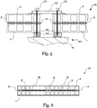
- Fig. 5 shows an example of the use of a plurality of light elements 10 according to the invention.
- these are provided at a distance from one another and each include the structure of the clamping device 20 just described.
- the screws 22 are guided here through the external sealing tape 4 on the edge of the light element 10.
- the intermediate space created between the light elements 10 is spanned by a cover 25, which is sealingly connected to the plates 2, so that no moisture can penetrate into the intermediate space.
- Fig. 7 an alternative method of assembly for the light element 10 according to the invention is shown.
- the light elements 10 are applied directly to a substrate 21.
- the cover 25 extends along a longitudinal direction of the cavities H.
- several screw (s) 22 arranged one behind the other, only one in section, are used in order to achieve a clamping force by means of the cover 25.
- the clamping device 20 of this exemplary embodiment thus manages with a smaller number of components.
- the assembly is thus simplified.
- the light element 10, in particular the sealing tape 4 is not penetrated.
- the sealing function of the sealing tape 4 can thus be guaranteed even with narrow sealing tapes 4.
- a light element 10 is compressed by means of the adhesive tape 5 and mounted in this state.
- a clamping bracket 26 known per se can be used, which is fixed on the building side.
- a screw 22 can then be guided through an elongated hole in the clamping bracket 26 and connected, for example, to a cover 25, so that the light element 10 is protected on all sides.
- the assembly takes place on a side which extends transversely to the longitudinal direction of the cavities H.
- the screw 22 only has to absorb a slight transverse force, at least during assembly, since the adhesive tape 5 functions here as a clamping device. The assembly is thus simplified. In this exemplary embodiment, too, there is no penetration of the light element.
- the clamping bracket 26 has at least one drainage opening at its foot point, so that backwater can be avoided.
- a light element 10 is shown which is essentially identical to that of the Fig. 8 matches.
- an edging profile 27 is used to set the second distance.
- the clamping angle includes a further step, which together with the edging profile 27 on a substrate 21, such as a Building that can be attached.
- the edging profile 27 consists of aluminum. It should be noted that also in the embodiment of Figure 8 a stable edging profile can be provided, which is arranged in accordance with the adhesive tape 5.
- “Building side” is understood within the scope of the invention to mean that the clamping device 20 is fixed on the side of a building, a building not only being a house, factory hall, etc. in the narrower sense, but rather any structure which is used for the installation of light elements 10 comes into question, for example also supporting structures for roofing gas stations, frames for holding windows, etc.
- light elements 10 were shown with only one chamber (a cavity H) in the exemplary embodiments described above, it is of course conceivable to provide longer or more plates 1, 2 and to subdivide the light element 10 into several cavities 10, e.g. if larger light elements 10 are provided should be.
- An example of the subdivision of a plate into several cavities H is shown schematically in FIG Fig. 6 made clear. The subdivision into several cavities increases the flexural rigidity of the light element 10 and counteracts any deflection of the light element.
- a light element 10 from more than two plates 1, 2 arranged one above the other. This can have a favorable influence on the thermal properties of the light element 10, for example by providing greater insulation for the light element 10 produced in this way.
- An asymmetrical structure with e.g. two upper 2, 2 and one lower 1 plate or with a second cavity H in the vertical direction with or without fabric 3 is also conceivable.
- the light element 10 can thus be adapted to individual needs. This modular design increases the degree of freedom of construction.
- the light element 10 is provided for an inclined installation.
- the end of the light element 10 lying further down in a height direction is placed in a U-shaped rail arranged at an appropriate angle on the building, which can be connected to the frame of the roof in the described or otherwise known manner.
- the clamping angle 26 can also be adjusted Fig. 8 can be used as a lower system.
- the cavities H extend perpendicular to the clamping bracket 26 according to FIG Fig. 8 .
- a fastening in the longitudinal direction of the cavities H can then preferably be done with a cover 25 according to FIG Fig. 7 respectively.
- coupling elements or light saddles can be formed in a simple manner.
- the orientation of the panels in relation to the building-side clamping devices 20, covers 25, clamping brackets 26 and the like is not limited to that described above. Rather, the plates can be oriented essentially as desired.
- a combination of a cover 25 arranged in the longitudinal direction of the cavity with a clamping bracket 26 arranged transversely thereto, which holds the panels in a lower position is suitable for a light saddle.
- the plates are to be arranged essentially horizontally only as a light band, for example, it is also conceivable to mount them only on the basis of the cover 25 or a clamping bracket 26.
- the mounting elements can then be aligned as desired across or lengthways to the cavities.
Landscapes
- Engineering & Computer Science (AREA)
- Architecture (AREA)
- Civil Engineering (AREA)
- Structural Engineering (AREA)
- Life Sciences & Earth Sciences (AREA)
- Wood Science & Technology (AREA)
- Building Environments (AREA)
- Arrangement Of Elements, Cooling, Sealing, Or The Like Of Lighting Devices (AREA)
- Securing Of Glass Panes Or The Like (AREA)
Priority Applications (1)
| Application Number | Priority Date | Filing Date | Title |
|---|---|---|---|
| SI202030116T SI3851604T1 (sl) | 2020-01-15 | 2020-12-29 | Svetilni element in metoda izdelave le-tega |
Applications Claiming Priority (1)
| Application Number | Priority Date | Filing Date | Title |
|---|---|---|---|
| DE102020100766.3A DE102020100766A1 (de) | 2020-01-15 | 2020-01-15 | Lichtelement und Verfahren zur Herstellung des Lichtelements |
Publications (2)
| Publication Number | Publication Date |
|---|---|
| EP3851604A1 true EP3851604A1 (fr) | 2021-07-21 |
| EP3851604B1 EP3851604B1 (fr) | 2022-07-27 |
Family
ID=74194472
Family Applications (1)
| Application Number | Title | Priority Date | Filing Date |
|---|---|---|---|
| EP20217495.9A Active EP3851604B1 (fr) | 2020-01-15 | 2020-12-29 | Élément lumineux et procédé de fabrication de l'élément lumineux |
Country Status (6)
| Country | Link |
|---|---|
| EP (1) | EP3851604B1 (fr) |
| DE (1) | DE102020100766A1 (fr) |
| DK (1) | DK3851604T3 (fr) |
| ES (1) | ES2927096T3 (fr) |
| PL (1) | PL3851604T3 (fr) |
| SI (1) | SI3851604T1 (fr) |
Cited By (1)
| Publication number | Priority date | Publication date | Assignee | Title |
|---|---|---|---|---|
| EP4229250A1 (fr) * | 2020-10-19 | 2023-08-23 | Edward Ward | Procédé et appareil de formation de panneau |
Citations (5)
| Publication number | Priority date | Publication date | Assignee | Title |
|---|---|---|---|---|
| US2273733A (en) * | 1940-06-26 | 1942-02-17 | Libbey Owens Ford Glass Co | Seal for double-walled glass units |
| US4335166A (en) * | 1980-11-21 | 1982-06-15 | Cardinal Insulated Glass Co. | Method of manufacturing a multiple-pane insulating glass unit |
| DE8512140U1 (de) * | 1985-04-24 | 1985-08-01 | Schülein, Werner, Dipl.-Ing., 8521 Spardorf | Zweischaliges Glaselement |
| WO2002038883A1 (fr) * | 2000-11-09 | 2002-05-16 | Deutsche Everlite Gmbh | Element lumineux |
| GB2464331A (en) * | 2008-07-03 | 2010-04-21 | David John Anderson | Glazing |
Family Cites Families (1)
| Publication number | Priority date | Publication date | Assignee | Title |
|---|---|---|---|---|
| GB9724077D0 (en) * | 1997-11-15 | 1998-01-14 | Dow Corning Sa | Insulating glass units |
-
2020
- 2020-01-15 DE DE102020100766.3A patent/DE102020100766A1/de not_active Withdrawn
- 2020-12-29 ES ES20217495T patent/ES2927096T3/es active Active
- 2020-12-29 DK DK20217495.9T patent/DK3851604T3/da active
- 2020-12-29 EP EP20217495.9A patent/EP3851604B1/fr active Active
- 2020-12-29 SI SI202030116T patent/SI3851604T1/sl unknown
- 2020-12-29 PL PL20217495.9T patent/PL3851604T3/pl unknown
Patent Citations (5)
| Publication number | Priority date | Publication date | Assignee | Title |
|---|---|---|---|---|
| US2273733A (en) * | 1940-06-26 | 1942-02-17 | Libbey Owens Ford Glass Co | Seal for double-walled glass units |
| US4335166A (en) * | 1980-11-21 | 1982-06-15 | Cardinal Insulated Glass Co. | Method of manufacturing a multiple-pane insulating glass unit |
| DE8512140U1 (de) * | 1985-04-24 | 1985-08-01 | Schülein, Werner, Dipl.-Ing., 8521 Spardorf | Zweischaliges Glaselement |
| WO2002038883A1 (fr) * | 2000-11-09 | 2002-05-16 | Deutsche Everlite Gmbh | Element lumineux |
| GB2464331A (en) * | 2008-07-03 | 2010-04-21 | David John Anderson | Glazing |
Cited By (1)
| Publication number | Priority date | Publication date | Assignee | Title |
|---|---|---|---|---|
| EP4229250A1 (fr) * | 2020-10-19 | 2023-08-23 | Edward Ward | Procédé et appareil de formation de panneau |
Also Published As
| Publication number | Publication date |
|---|---|
| DE102020100766A1 (de) | 2021-07-15 |
| DK3851604T3 (da) | 2022-09-12 |
| ES2927096T3 (es) | 2022-11-02 |
| EP3851604B1 (fr) | 2022-07-27 |
| SI3851604T1 (sl) | 2023-01-31 |
| PL3851604T3 (pl) | 2022-12-27 |
Similar Documents
| Publication | Publication Date | Title |
|---|---|---|
| DE69722241T2 (de) | Ein verbessertes verkleidungsplattenbefestigungssystem | |
| EP2404007B1 (fr) | Baguette profilee munie d'un dispositif d'etancheite pour assurer l'etancheite de joints entre deux elements | |
| EP2411594B1 (fr) | Profilé de retenue, dispositif de serrage et élément de façade | |
| CH699782A2 (de) | Rahmenanschlussteil zur Befestigung an einem Rahmen. | |
| DE202009006044U1 (de) | Stockrahmen und/oder Flügelrahmen | |
| EP1978171B1 (fr) | Façade avec montants et traverses en construction modulaire | |
| EP3851604B1 (fr) | Élément lumineux et procédé de fabrication de l'élément lumineux | |
| EP2492429A2 (fr) | Bande de crépissage ainsi qu'angles de construction dotés d'une bande de crépissage | |
| DE4206345C2 (de) | Verfahren und Vorrichtung zum Befestigen von Fassadenplatten | |
| DE3201083A1 (de) | Abdeckvorrichtung, insbesondere fuer eine sockelfuge | |
| DE102010015956A1 (de) | Eckausbildung bei Wohnkabinen von Reisemobilen | |
| DE102008057798B4 (de) | Zweiteiliges Laibungsanschlussprofil | |
| EP0365773A1 (fr) | Cloison | |
| EP0149443A2 (fr) | Liaison de serrage entre panneaux doubles munis de traverses et un profilé, notamment pour des petites serres | |
| EP2811239B1 (fr) | Entretoise | |
| EP1353035A2 (fr) | Fenêtre ou porte | |
| EP3085873B1 (fr) | Panneau a effet | |
| EP2878741B1 (fr) | Élément de construction sous forme de panneaux d'isolation ou de plaque de façade montés en sandwich avec un panneau extern vitreux | |
| DE20220890U1 (de) | Befestigungsvorrichtung für Dämmstoffplatten | |
| EP2453094A2 (fr) | Bande en silicone pour la fermeture élastique d'assemblages | |
| EP2463471B1 (fr) | Procédé de raccordement d'éléments muraux | |
| DE4446412A1 (de) | Oberlichtelement | |
| EP3587701B1 (fr) | Agencement de profilé de plâtre pour étanchéifier un joint | |
| DE29922509U1 (de) | Einbaudichtung von Bauteilen an Fahrzeugen, insbesondere an Wohnmobilen und Wohnwagen | |
| EP3276100A1 (fr) | Système d'étanchéité pour un système de paroi |
Legal Events
| Date | Code | Title | Description |
|---|---|---|---|
| PUAI | Public reference made under article 153(3) epc to a published international application that has entered the european phase |
Free format text: ORIGINAL CODE: 0009012 |
|
| STAA | Information on the status of an ep patent application or granted ep patent |
Free format text: STATUS: REQUEST FOR EXAMINATION WAS MADE |
|
| 17P | Request for examination filed |
Effective date: 20201229 |
|
| AK | Designated contracting states |
Kind code of ref document: A1 Designated state(s): AL AT BE BG CH CY CZ DE DK EE ES FI FR GB GR HR HU IE IS IT LI LT LU LV MC MK MT NL NO PL PT RO RS SE SI SK SM TR |
|
| REG | Reference to a national code |
Ref country code: DE Ref legal event code: R079 Ref document number: 502020001430 Country of ref document: DE Free format text: PREVIOUS MAIN CLASS: E04C0002540000 Ipc: E04C0001420000 |
|
| RIC1 | Information provided on ipc code assigned before grant |
Ipc: E04C 2/54 20060101ALI20211216BHEP Ipc: E04C 2/24 20060101ALI20211216BHEP Ipc: E04C 1/42 20060101AFI20211216BHEP |
|
| GRAP | Despatch of communication of intention to grant a patent |
Free format text: ORIGINAL CODE: EPIDOSNIGR1 |
|
| STAA | Information on the status of an ep patent application or granted ep patent |
Free format text: STATUS: GRANT OF PATENT IS INTENDED |
|
| INTG | Intention to grant announced |
Effective date: 20220215 |
|
| GRAS | Grant fee paid |
Free format text: ORIGINAL CODE: EPIDOSNIGR3 |
|
| GRAA | (expected) grant |
Free format text: ORIGINAL CODE: 0009210 |
|
| STAA | Information on the status of an ep patent application or granted ep patent |
Free format text: STATUS: THE PATENT HAS BEEN GRANTED |
|
| AK | Designated contracting states |
Kind code of ref document: B1 Designated state(s): AL AT BE BG CH CY CZ DE DK EE ES FI FR GB GR HR HU IE IS IT LI LT LU LV MC MK MT NL NO PL PT RO RS SE SI SK SM TR |
|
| REG | Reference to a national code |
Ref country code: CH Ref legal event code: EP |
|
| REG | Reference to a national code |
Ref country code: DE Ref legal event code: R096 Ref document number: 502020001430 Country of ref document: DE |
|
| REG | Reference to a national code |
Ref country code: AT Ref legal event code: REF Ref document number: 1507163 Country of ref document: AT Kind code of ref document: T Effective date: 20220815 |
|
| REG | Reference to a national code |
Ref country code: IE Ref legal event code: FG4D Free format text: LANGUAGE OF EP DOCUMENT: GERMAN |
|
| REG | Reference to a national code |
Ref country code: RO Ref legal event code: EPE |
|
| REG | Reference to a national code |
Ref country code: DK Ref legal event code: T3 Effective date: 20220905 |
|
| REG | Reference to a national code |
Ref country code: NL Ref legal event code: FP |
|
| REG | Reference to a national code |
Ref country code: ES Ref legal event code: FG2A Ref document number: 2927096 Country of ref document: ES Kind code of ref document: T3 Effective date: 20221102 |
|
| REG | Reference to a national code |
Ref country code: LT Ref legal event code: MG9D |
|
| REG | Reference to a national code |
Ref country code: SK Ref legal event code: T3 Ref document number: E 40681 Country of ref document: SK |
|
| PG25 | Lapsed in a contracting state [announced via postgrant information from national office to epo] |
Ref country code: SE Free format text: LAPSE BECAUSE OF FAILURE TO SUBMIT A TRANSLATION OF THE DESCRIPTION OR TO PAY THE FEE WITHIN THE PRESCRIBED TIME-LIMIT Effective date: 20220727 Ref country code: RS Free format text: LAPSE BECAUSE OF FAILURE TO SUBMIT A TRANSLATION OF THE DESCRIPTION OR TO PAY THE FEE WITHIN THE PRESCRIBED TIME-LIMIT Effective date: 20220727 Ref country code: PT Free format text: LAPSE BECAUSE OF FAILURE TO SUBMIT A TRANSLATION OF THE DESCRIPTION OR TO PAY THE FEE WITHIN THE PRESCRIBED TIME-LIMIT Effective date: 20221128 Ref country code: NO Free format text: LAPSE BECAUSE OF FAILURE TO SUBMIT A TRANSLATION OF THE DESCRIPTION OR TO PAY THE FEE WITHIN THE PRESCRIBED TIME-LIMIT Effective date: 20221027 Ref country code: LV Free format text: LAPSE BECAUSE OF FAILURE TO SUBMIT A TRANSLATION OF THE DESCRIPTION OR TO PAY THE FEE WITHIN THE PRESCRIBED TIME-LIMIT Effective date: 20220727 Ref country code: LT Free format text: LAPSE BECAUSE OF FAILURE TO SUBMIT A TRANSLATION OF THE DESCRIPTION OR TO PAY THE FEE WITHIN THE PRESCRIBED TIME-LIMIT Effective date: 20220727 Ref country code: FI Free format text: LAPSE BECAUSE OF FAILURE TO SUBMIT A TRANSLATION OF THE DESCRIPTION OR TO PAY THE FEE WITHIN THE PRESCRIBED TIME-LIMIT Effective date: 20220727 |
|
| PG25 | Lapsed in a contracting state [announced via postgrant information from national office to epo] |
Ref country code: IS Free format text: LAPSE BECAUSE OF FAILURE TO SUBMIT A TRANSLATION OF THE DESCRIPTION OR TO PAY THE FEE WITHIN THE PRESCRIBED TIME-LIMIT Effective date: 20221127 Ref country code: HR Free format text: LAPSE BECAUSE OF FAILURE TO SUBMIT A TRANSLATION OF THE DESCRIPTION OR TO PAY THE FEE WITHIN THE PRESCRIBED TIME-LIMIT Effective date: 20220727 Ref country code: GR Free format text: LAPSE BECAUSE OF FAILURE TO SUBMIT A TRANSLATION OF THE DESCRIPTION OR TO PAY THE FEE WITHIN THE PRESCRIBED TIME-LIMIT Effective date: 20221028 |
|
| PG25 | Lapsed in a contracting state [announced via postgrant information from national office to epo] |
Ref country code: SM Free format text: LAPSE BECAUSE OF FAILURE TO SUBMIT A TRANSLATION OF THE DESCRIPTION OR TO PAY THE FEE WITHIN THE PRESCRIBED TIME-LIMIT Effective date: 20220727 |
|
| REG | Reference to a national code |
Ref country code: DE Ref legal event code: R097 Ref document number: 502020001430 Country of ref document: DE |
|
| PG25 | Lapsed in a contracting state [announced via postgrant information from national office to epo] |
Ref country code: EE Free format text: LAPSE BECAUSE OF FAILURE TO SUBMIT A TRANSLATION OF THE DESCRIPTION OR TO PAY THE FEE WITHIN THE PRESCRIBED TIME-LIMIT Effective date: 20220727 |
|
| PLBE | No opposition filed within time limit |
Free format text: ORIGINAL CODE: 0009261 |
|
| STAA | Information on the status of an ep patent application or granted ep patent |
Free format text: STATUS: NO OPPOSITION FILED WITHIN TIME LIMIT |
|
| PG25 | Lapsed in a contracting state [announced via postgrant information from national office to epo] |
Ref country code: AL Free format text: LAPSE BECAUSE OF FAILURE TO SUBMIT A TRANSLATION OF THE DESCRIPTION OR TO PAY THE FEE WITHIN THE PRESCRIBED TIME-LIMIT Effective date: 20220727 |
|
| 26N | No opposition filed |
Effective date: 20230502 |
|
| PG25 | Lapsed in a contracting state [announced via postgrant information from national office to epo] |
Ref country code: IE Free format text: LAPSE BECAUSE OF NON-PAYMENT OF DUE FEES Effective date: 20221229 |
|
| PG25 | Lapsed in a contracting state [announced via postgrant information from national office to epo] |
Ref country code: CY Free format text: LAPSE BECAUSE OF FAILURE TO SUBMIT A TRANSLATION OF THE DESCRIPTION OR TO PAY THE FEE WITHIN THE PRESCRIBED TIME-LIMIT Effective date: 20220727 |
|
| PG25 | Lapsed in a contracting state [announced via postgrant information from national office to epo] |
Ref country code: MK Free format text: LAPSE BECAUSE OF FAILURE TO SUBMIT A TRANSLATION OF THE DESCRIPTION OR TO PAY THE FEE WITHIN THE PRESCRIBED TIME-LIMIT Effective date: 20220727 |
|
| PG25 | Lapsed in a contracting state [announced via postgrant information from national office to epo] |
Ref country code: MC Free format text: LAPSE BECAUSE OF FAILURE TO SUBMIT A TRANSLATION OF THE DESCRIPTION OR TO PAY THE FEE WITHIN THE PRESCRIBED TIME-LIMIT Effective date: 20220727 |
|
| PG25 | Lapsed in a contracting state [announced via postgrant information from national office to epo] |
Ref country code: MC Free format text: LAPSE BECAUSE OF FAILURE TO SUBMIT A TRANSLATION OF THE DESCRIPTION OR TO PAY THE FEE WITHIN THE PRESCRIBED TIME-LIMIT Effective date: 20220727 |
|
| PG25 | Lapsed in a contracting state [announced via postgrant information from national office to epo] |
Ref country code: BG Free format text: LAPSE BECAUSE OF FAILURE TO SUBMIT A TRANSLATION OF THE DESCRIPTION OR TO PAY THE FEE WITHIN THE PRESCRIBED TIME-LIMIT Effective date: 20220727 |
|
| PG25 | Lapsed in a contracting state [announced via postgrant information from national office to epo] |
Ref country code: MT Free format text: LAPSE BECAUSE OF FAILURE TO SUBMIT A TRANSLATION OF THE DESCRIPTION OR TO PAY THE FEE WITHIN THE PRESCRIBED TIME-LIMIT Effective date: 20220727 |
|
| PG25 | Lapsed in a contracting state [announced via postgrant information from national office to epo] |
Ref country code: HU Free format text: LAPSE BECAUSE OF FAILURE TO SUBMIT A TRANSLATION OF THE DESCRIPTION OR TO PAY THE FEE WITHIN THE PRESCRIBED TIME-LIMIT; INVALID AB INITIO Effective date: 20201229 |
|
| GBPC | Gb: european patent ceased through non-payment of renewal fee |
Effective date: 20241229 |
|
| PG25 | Lapsed in a contracting state [announced via postgrant information from national office to epo] |
Ref country code: GB Free format text: LAPSE BECAUSE OF NON-PAYMENT OF DUE FEES Effective date: 20241229 |
|
| PG25 | Lapsed in a contracting state [announced via postgrant information from national office to epo] |
Ref country code: TR Free format text: LAPSE BECAUSE OF FAILURE TO SUBMIT A TRANSLATION OF THE DESCRIPTION OR TO PAY THE FEE WITHIN THE PRESCRIBED TIME-LIMIT Effective date: 20220727 |
|
| REG | Reference to a national code |
Ref country code: CH Ref legal event code: U11 Free format text: ST27 STATUS EVENT CODE: U-0-0-U10-U11 (AS PROVIDED BY THE NATIONAL OFFICE) Effective date: 20260101 |
|
| PGFP | Annual fee paid to national office [announced via postgrant information from national office to epo] |
Ref country code: DE Payment date: 20251125 Year of fee payment: 6 |
|
| PGFP | Annual fee paid to national office [announced via postgrant information from national office to epo] |
Ref country code: AT Payment date: 20251215 Year of fee payment: 6 |
|
| PGFP | Annual fee paid to national office [announced via postgrant information from national office to epo] |
Ref country code: DK Payment date: 20251217 Year of fee payment: 6 |
|
| PGFP | Annual fee paid to national office [announced via postgrant information from national office to epo] |
Ref country code: LU Payment date: 20251216 Year of fee payment: 6 Ref country code: FR Payment date: 20251217 Year of fee payment: 6 Ref country code: NL Payment date: 20251217 Year of fee payment: 6 |
|
| PGFP | Annual fee paid to national office [announced via postgrant information from national office to epo] |
Ref country code: BE Payment date: 20251223 Year of fee payment: 6 |
|
| PGFP | Annual fee paid to national office [announced via postgrant information from national office to epo] |
Ref country code: CZ Payment date: 20251216 Year of fee payment: 6 |
|
| PGFP | Annual fee paid to national office [announced via postgrant information from national office to epo] |
Ref country code: PL Payment date: 20251118 Year of fee payment: 6 |
|
| PGFP | Annual fee paid to national office [announced via postgrant information from national office to epo] |
Ref country code: SK Payment date: 20251222 Year of fee payment: 6 Ref country code: RO Payment date: 20251218 Year of fee payment: 6 |
|
| PGFP | Annual fee paid to national office [announced via postgrant information from national office to epo] |
Ref country code: SI Payment date: 20251217 Year of fee payment: 6 |
|
| PGFP | Annual fee paid to national office [announced via postgrant information from national office to epo] |
Ref country code: ES Payment date: 20260119 Year of fee payment: 6 |
|
| PGFP | Annual fee paid to national office [announced via postgrant information from national office to epo] |
Ref country code: IT Payment date: 20251231 Year of fee payment: 6 |
|
| PGFP | Annual fee paid to national office [announced via postgrant information from national office to epo] |
Ref country code: CH Payment date: 20260101 Year of fee payment: 6 |