EP3851616B1 - Ancre de transport pourvue de bande de maintien - Google Patents
Ancre de transport pourvue de bande de maintien Download PDFInfo
- Publication number
- EP3851616B1 EP3851616B1 EP20152603.5A EP20152603A EP3851616B1 EP 3851616 B1 EP3851616 B1 EP 3851616B1 EP 20152603 A EP20152603 A EP 20152603A EP 3851616 B1 EP3851616 B1 EP 3851616B1
- Authority
- EP
- European Patent Office
- Prior art keywords
- anchoring
- clevis
- strap
- limbs
- concrete
- Prior art date
- Legal status (The legal status is an assumption and is not a legal conclusion. Google has not performed a legal analysis and makes no representation as to the accuracy of the status listed.)
- Active
Links
Images


Classifications
-
- E—FIXED CONSTRUCTIONS
- E04—BUILDING
- E04G—SCAFFOLDING; FORMS; SHUTTERING; BUILDING IMPLEMENTS OR AIDS, OR THEIR USE; HANDLING BUILDING MATERIALS ON THE SITE; REPAIRING, BREAKING-UP OR OTHER WORK ON EXISTING BUILDINGS
- E04G21/00—Preparing, conveying, or working-up building materials or building elements in situ; Other devices or measures for constructional work
- E04G21/14—Conveying or assembling building elements
- E04G21/142—Means in or on the elements for connecting same to handling apparatus
- E04G21/145—Means in or on the elements for connecting same to handling apparatus specific for hollow plates
-
- B—PERFORMING OPERATIONS; TRANSPORTING
- B25—HAND TOOLS; PORTABLE POWER-DRIVEN TOOLS; MANIPULATORS
- B25B—TOOLS OR BENCH DEVICES NOT OTHERWISE PROVIDED FOR, FOR FASTENING, CONNECTING, DISENGAGING OR HOLDING
- B25B5/00—Clamps
- B25B5/14—Clamps for work of special profile
- B25B5/145—Clamps for work of special profile for plates
Definitions
- the invention relates to a transport anchor, in particular for hollow walls or double or multiple concrete walls, each with opposing concrete shells according to claim 1.
- the invention also relates to a method for producing such a transport anchor according to claim 9.
- transport anchor filament anchor
- the transport anchor essentially comprises a clevis and a crossbar or a cross brace.
- the parallel, opposite ends of the load bracket serve as anchoring legs for embedding in concrete in a concrete shell. They are connected to one another by a center section of the yoke that is generally curved once or several times and are held apart or at a predetermined distance from one another by the cross brace. This is to prevent the anchoring legs from contracting and tearing out of the concrete shells when the wall is lifted.
- the cross brace is attached to the anchoring legs in a movable, displaceable manner or by means of welded connections or tacking, with the entire lifting bracket of the transport anchor being stiffened.
- a clevis comprising a clevis center section and the anchoring legs of the lifting anchor is often provided by bending rebar using a bending machine.
- a problem with such a manufacturing process is that the rebars used as the starting material are not always the same. Tolerances of the rebar exist with regard to the strength, the dimensions, in particular the diameter, the roundness and the dimensions of the ribs of the rebar. If these rebars are then processed into lifting anchors, each bent lifting anchor can have different external dimensions when measured afterwards. These deviations are amplified by manufacturing tolerances of the bending machine and temperature differences in the steel.
- the distance between the two anchoring legs is particularly affected by these deviations, since the loose anchoring legs can easily be bent during production, storage, transport or installation of the lifting anchor in the precast concrete plant. These deviations in the outer dimensions of the lifting anchor are undesirable and problematic for installation and operational safety.
- the anchoring legs are further conically bent, i.e. the lifting anchor becomes wider towards the anchoring leg end sections, the concrete cover on the outside of the concrete double wall falls below the required minimum thickness. This can result in rust damage to the transport anchor.
- the anchoring legs require a concrete cover of 10mm. Even a slight bending up of the anchoring leg, which results in a 1 mm increase in the distance between the end sections of the anchoring leg, reduces the concrete cover by a full 10%. If, on the other hand, the anchoring limbs are pressed together, the transport anchor becomes narrower towards the anchoring limb end sections and the distance between the anchoring limb end sections can be less than the length of the cross brace.
- the lifting anchors for concrete double walls also have an additional cross brace on the anchoring leg end sections, which is welded to the anchoring legs in the area of the anchoring leg end sections.
- the DE 10 2016 119352 A1 provides a lifting anchor with a where the cross brace is concrete.
- a fixing element can connect the anchor legs to one another, preferably by welding. This fixing element enables the anchoring legs to be shortened or prevents them from floating up.
- the object of the invention is to improve the operational safety of the known transport anchor and to reduce the risk of errors during installation.
- a lifting anchor with two anchoring legs which connects two concrete shells of a double wall, is usually assumed below.
- a clevis typically has two anchoring legs, with one anchoring leg each being cast or capable of being cast for casting in a concrete shell or concrete wall of a double wall.
- the clevis center section is preferably located in a space between the opposing concrete shells.
- the crossbar can also be arranged in this intermediate space and absorbs the pressure and/or tensile forces when lifting or erecting the double wall on the transport anchor and thus stabilizes the transport anchor when the load is picked up.
- the cross brace can be designed as a spacer device or other device for maintaining the distance between the anchoring legs.
- a holding device which also includes the anchoring legs of the transport anchor at at least two contact points, additionally stabilizes the individual sections of the load bracket and the cross brace in the load bracket.
- the desired shape of the lifting anchor set during manufacture can also be maintained during storage and installation, in particular through the interaction of the cross brace and holding device. This simplifies handling when installing the transport anchor in the double wall to be manufactured and increases installation safety.
- Releasable fastening means that the holding device can be removed without being destroyed before, after and/or during installation, or at least loses its holding power as a result of being destroyed.
- the holding device preferably comprises or encompasses an anchoring leg assigned to a first concrete shell and an anchoring leg assigned to a second concrete shell.
- Encompassing means that the holding device forms a form-fitting and/or frictional and/or material-locking holding connection with both anchoring legs, so that the anchoring legs are locked and fixed in a predetermined position relative to one another for installation.
- the one clevis width specified for operational safety is not exceeded in the area of the anchoring legs.
- the required concrete cover on the outside of the double wall can thus be maintained and rust damage to the lifting anchor can be avoided.
- the holding device forms a frictional holding contact with the anchoring leg assigned to the first concrete shell and/or the anchoring leg assigned to the second concrete shell.
- the anchoring legs run essentially parallel. Nevertheless, during the manufacture of the clevis when pre-bending an extruded body, provision can initially be made for the anchoring legs to run more or less conically in relation to one another and open towards the anchoring leg end sections. In other words, the distance between the anchoring legs increases starting from the transition curves towards the leg end sections. After inserting and possibly fastening the cross brace, the anchoring leg end sections are pressed inwards, ie towards the body axis, so that the anchoring legs align parallel to one another or close towards the anchoring leg end sections. This creates a pretension in the load bracket, which can be permanently maintained for transport and/or installation by the frictional holding contacts of the holding device.
- the anchoring limbs are pressed further outwards by a suitable holding device, so that the distance between the anchoring limb end sections increases further.
- the preload can be maintained, for example, by a holding device (see Fig.2a ) which encompasses or surrounds the cross brace and the clevis middle section.
- the holding device is designed as a band-like, preferably flexible and/or taut, holding band, for example a packaging band.
- the retaining strap is wrapped around the load bracket in the area of the anchoring legs at least once so that the anchoring legs are gripped from behind.
- the tether comes to rest with the anchoring limbs on the area of the anchoring limbs facing away from the body axis and maintains a pretension in the clevis which may be necessary for the desired alignment of the anchoring limbs.
- the retaining strap can be designed as an inexpensive packaging strap, which can be removed by cutting at any installation step.
- the anchoring limbs in particular the anchoring limb end sections, are preferably fixed and/or locked by the holding device in a predetermined position of the anchoring limbs relative to one another.
- a predetermined position means that, in particular in the area of the anchoring leg end sections, the width is neither exceeded nor fallen below a predetermined load bracket. This ensures that the penetration depth of the anchoring leg end sections into the concrete body of the concrete shell is maximum or corresponds to the desired amount. In particular, it is avoided that the anchoring leg distances in the area of the anchoring leg end sections are smaller than in the area of the cross brace or the transition curves and thus the transport anchor legs are not anchored deep enough in the concrete. The anchoring leg end sections remain precisely positioned by the holding device and the transport anchors can safely carry the load of the component.
- the cross brace or other spacer device is attached to the anchoring leg or legs in a sliding manner and/or in frictional engagement.
- a transition curve is formed between the middle section of the shackle and the at least two anchoring legs, with the cross brace in the area of the transition curves passing through a second holding device, in particular by a second holding strap, is held, the first holding device spanning the at least two anchoring legs in the region of the anchoring leg end sections.
- the anchoring legs usually transition into the middle section of the lifting anchor clevis via a transition curve, transition bend or transition kink.
- the cross brace is positioned in such a way that it adjoins, abuts or bears against the curved transition area of the middle section of the yoke. So that there is no need for welding or any other joining method for a non-detachable connection, the position of the cross brace is fixed by compressive forces which are exerted by both anchoring legs on the two end regions of the cross brace, with the compressive forces being essentially parallel to the longitudinal axis of the cross brace and perpendicular facing the anchoring legs.
- the compressive force is provided by both anchoring legs being pressed in the direction of the body axis of the transport anchor and the resultant tensioning force or prestressing in the strand body of the load clip being permanently fixed by a holding device in the area of the anchoring leg end sections until the holding device is removed or destroyed.
- the first holding device is a holding strap that encircles the two anchoring legs, i.e. grasps around or behind them, and can prevent the pretension generated in the clevis from loosening again.
- the cross brace can be held in the yoke by frictional retaining contacts and/or joining methods such as welding.
- a second retaining strap or other retaining device is tensioned to fix the position of the cross strut in contact with the cross strut and the clevis blank and/or the clevis.
- the cross brace is held in a predetermined position, preferably in the region of the transition curves, by the second retaining strap.
- additional joining methods for fastening the cross brace can be omitted.
- the tensioning force of the retaining strap resulting from the tensioning process presses the cross brace in the area of the transition curves against the middle section of the yoke. This creates a holding force of the transition curves on the cross brace, which prevents the cross brace from slipping sideways or radially in the transport anchor.
- the frictional contact is preferably realized at two contact points between the two end areas of the cross brace and the anchoring legs, in particular in the area of the transition curves, that is to say in the straight area of the attachment triangle for the attachment means. Since the blank clevis has previously been manufactured in such a way that the distance between the anchoring legs increases towards the end sections of the anchoring limbs, the realization of the contact contacts results in a pretension in the clevis. This pretension can be fixed, for example, by tightly wrapping the load bracket in the area of the anchoring leg with a packing tape.
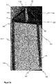
- figure 1 shows a transport anchor from the prior art with a clevis 100 made of highly ductile rebar, and a cross brace 200 made of a steel tube that is pressed flat in its end areas 201 .
- the one-piece yoke 100 with an approximately U-shaped basic shape, its rectilinear, parallel, opposite end sections each form an anchoring leg 101, which merges into a central section 103 of the yoke via a transition curve 102 in each case.
- the yoke middle section 103 connects the two anchoring legs 101, with the yoke middle section 103 external load bearing and/or means of transport, for example crane hooks (not shown), can be coupled or engaged.
- a body axis 107 of the transport anchor can essentially correspond to an axis of symmetry of the transport anchor, the clevis 100 and/or a mirror axis between the anchor legs 101 .
- the ends of the anchoring legs 101 facing away from the central section 103 of the yoke, the end sections 104 of the anchoring limbs, run parallel to one another, so that the width 105 of the yoke in the area of the end sections of the anchoring limb 104 corresponds to the width of the yoke 105 in the area of the transition curve 102.
- a predetermined anchoring leg distance 106 ie the distance between the anchoring legs 101, should not be undershot.
- the cross strut 200 is designed in its end areas 201 at the same time with guide recesses 202, in which the respective ribbed steel strand body of the anchoring leg 101 is accommodated with frictional engagement and slidingly displaceable against a frictional force.
- the arrangement shown is further provided with a holding device 300 in the form of a relatively wide packaging tape 301a, which is wrapped around the middle part of the yoke center section 103 and around a cross brace middle section 203 in order to hold the cross brace 200 and the clevis 100 in a certain relative position to one another.
- the wide side of the packaging tape that is visible to the outside can be used as an information carrier for the reproduction of various information 303 .
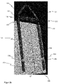
- Figure 2a shows a lifting anchor, in contrast to the lifting anchor according to FIG figure 1 the packaging tape or the retaining tape 301 is wound with tension around the middle part of the middle section 103 of the bracket and around the middle section of the cross brace 203, so that a frictional holding contact 304 is formed with the cross brace 200 and a frictional holding contact is formed with the middle section of the load bow 103 and the cross brace 200 in the region of the transition curves 102, a frictional contact 150 with the load bracket 100 is realized.
- the frictional contact 150 also contributes to keeping the anchoring legs 101 of the load clip 100 in a specific position relative to one another.
- Figure 2b shows a transport anchor with a first retaining strap 302 in the area of the anchoring limbs 101, in particular in the area of the anchoring limb end sections 104.
- the anchoring legs 101 are preferably initially aligned in such a way that the distance 106 between the anchoring legs 101 increases, starting from the transition curves 102 towards the end sections 104 of the legs.
- the anchoring leg end sections 104 are pressed inwards, ie towards the body axis 107, so that the anchoring legs 101 run parallel and contact contacts 150 are formed between the cross brace 200 and the transition curves 102.
- the first tether 302 is wound tightly at least once around the clevis 100 on the outside in the area of the anchoring legs 101, so that the anchoring legs 101 are gripped from behind.
- the tether 302 forms holding contacts 304 on a region of the respective anchoring leg 101 facing away from the body axis 107 and maintains the pretension in the clevis 100 , the pretension being necessary for the anchoring limb 101 to rest 150 on the cross brace 200 .
- Figure 2c combines the tether 301 out Figure 2a and the first tether 302 off Figure 2b .
- the subsequent assembly of the first tether 302 is facilitated, in particular for a manual assembly of the first tether 302.
- a total of four friction-locking holding contacts 304 are provided by two holding straps 301, 302, which hold the transport anchor in the desired position and ensure installation in accordance with the installation instructions.
- adhesive tapes can also be used.
- retaining straps 301, 302 can also be tightened in the transport anchor.
Landscapes
- Engineering & Computer Science (AREA)
- Architecture (AREA)
- Mechanical Engineering (AREA)
- Civil Engineering (AREA)
- Structural Engineering (AREA)
- Joining Of Building Structures In Genera (AREA)
- Reinforcement Elements For Buildings (AREA)
Claims (11)
- Ancre de transport, en particulier pour des parois creuses ou des parois en béton doubles ou multiples, respectivement avec des coques en béton opposées, dans laquelle l'ancre de transport présente ce qui suit :- un étrier de charge (100) avec au moins deux branches d'ancrage (101), au moins une branche d'ancrage (101) pouvant être affectée à une coque en béton ou à un mur en béton,- un tronçon central d'étrier de charge (103), par lequel lesdites au moins deux branches d'ancrage (101) sont reliées entre elles, dans lequel avec le tronçon central d'étrier de charge (103), des moyens externes de réception et/ou de transport de charge peuvent être couplés ou mis en prise,- au moins une entretoise (200) ou un autre dispositif d'écartement qui, pour absorber les charges de compression ou de traction entre les branches d'ancrage (101), est agencée transversalement ou en oblique par rapport à une direction longitudinale de la ou des branches d'ancrage (101) ou à un axe de corps (107) de l'ancre de transport,- au moins un premier dispositif de retenue (300), qui est conçu comme une première bande de retenue (302) ayant la forme d'un ruban,caractérisée en ce que
la première bande de retenue (302) relie lesdites au moins deux branches d'ancrage (101). - Ancre de transport selon la revendication 1,
caractérisée en ce que
au moins un deuxième dispositif de retenue (300) est conçu comme une deuxième bande de retenue (301) ayant la forme d'un ruban et relie le tronçon central d'étrier de charge (103) et la traverse (200). - Ancre de transport selon l'une des revendications 1 ou 2,
caractérisée en ce que
la bande ou les bandes de retenue (301, 302) sont conçues pour être flexibles ou tendues. - Ancre de transport selon l'une des revendications précédentes, caractérisée en ce que la première bande de retenue (302) relie une branche d'ancrage (101) pouvant être associée
à une première coque en béton et une branche d'ancrage (101) pouvant être associée à une deuxième coque en béton. - Ancre de transport selon la revendication précédente,
caractérisée en ce que
la première bande de retenue (302) forme un contact de retenue par friction (304) avec la branche d'ancrage (101) pouvant être associée à la première coque en béton et avec la branche d'ancrage (101) pouvant être associée à la deuxième coque en béton. - Ancre de transport selon l'une des revendications précédentes,
caractérisée en ce que
les branches d'ancrage (101), en particulier les tronçons d'extrémités de branches d'ancrage (104), sont fixées et/ou bloquées dans une position prédéterminée l'une par rapport à l'autre par la première bande de retenue (302). - Ancre de transport selon l'une quelconque des revendications précédentes,
caractérisée en ce que
la traverse (200) ou autre dispositif d'écartement est montée sur la ou les branches d'ancrage (101) de manière à pouvoir coulisser et/ou être en appui par friction (150). - Ancre de transport selon la revendication 7,
caractérisée en ce que
une courbure de transition (102) est formée entre le tronçon central d'étrier de charge (103) et les au moins deux branches d'ancrage (101), la traverse (200) étant maintenue dans la zone des courbures de transition (102) par la première bande de retenue (302), la première bande de retenue entourant les au moins deux branches d'ancrage (101) dans la zone des tronçons d'extrémité (104) des branches d'ancrage. - Procédé de fabrication d'une ancre de transport, en particulier d'une ancre de transport selon l'une quelconque des revendications 1 à 8,
comprenant les étapes suivantes :- préparation d'un corps extrudé pour étrier de charge, de préférence en acier nervuré pour béton, pour la fabrication de l'étrier de charge (100),- pliage ou pré-pliage du corps extrudé pour étrier de charge pour la fabrication d'un étrier de charge (100) ou d'une ébauche d'étrier de charge avec une forme de base à peu près en U avec formation de∘ au moins deux branches d'ancrage (101),∘ un tronçon central d'étrier de charge (103) disposé entre les deux branches d'ancrage (101) et∘ des courbures de transition (102) disposées entre le tronçon central d'étrier de charge (103) et les deux branches d'ancrage (101),- insertion d'une entretoise (200) entre les branches d'ancrage (101), en particulier entre les courbures de transition (102),- tension d'une première bande de retenue (302) pour fixer la position des branches d'ancrage (101)dans lequelavant ou pendant la tension de la première bande de retenue (302), les deux branches d'ancrage (101) sont déplacées en formant une précontrainte dans l'ébauche d'étrier de charge pour venir en appui (150) avec la traverse (200),pour fixer la position des branches d'ancrage (101) dans cet appui (150), la première bande de retenue (302) est tendue autour des branches d'ancrage (101). - Procédé selon la revendication 9,
caractérisé en ce que
l'appui (150) est à friction entre l'ébauche d'étrier de charge et la traverse (200). - Procédé selon l'une des revendications 9 ou 10,
caractérisé en ce que
après la mise en place de la traverse (200), une deuxième bande de retenue (301) ou un autre dispositif de maintien (300) est tendue en appui (304) avec la barre transversale (200) et l'ébauche d'étrier de charge ou l'étrier de charge (100) pour fixer la position de la traverse (200).
Priority Applications (2)
| Application Number | Priority Date | Filing Date | Title |
|---|---|---|---|
| EP20152603.5A EP3851616B1 (fr) | 2020-01-20 | 2020-01-20 | Ancre de transport pourvue de bande de maintien |
| EP20181897.8A EP3851617B1 (fr) | 2020-01-20 | 2020-06-24 | Module pourvu d'aide au montage pour ancres de transport |
Applications Claiming Priority (1)
| Application Number | Priority Date | Filing Date | Title |
|---|---|---|---|
| EP20152603.5A EP3851616B1 (fr) | 2020-01-20 | 2020-01-20 | Ancre de transport pourvue de bande de maintien |
Publications (2)
| Publication Number | Publication Date |
|---|---|
| EP3851616A1 EP3851616A1 (fr) | 2021-07-21 |
| EP3851616B1 true EP3851616B1 (fr) | 2022-10-12 |
Family
ID=69187546
Family Applications (2)
| Application Number | Title | Priority Date | Filing Date |
|---|---|---|---|
| EP20152603.5A Active EP3851616B1 (fr) | 2020-01-20 | 2020-01-20 | Ancre de transport pourvue de bande de maintien |
| EP20181897.8A Active EP3851617B1 (fr) | 2020-01-20 | 2020-06-24 | Module pourvu d'aide au montage pour ancres de transport |
Family Applications After (1)
| Application Number | Title | Priority Date | Filing Date |
|---|---|---|---|
| EP20181897.8A Active EP3851617B1 (fr) | 2020-01-20 | 2020-06-24 | Module pourvu d'aide au montage pour ancres de transport |
Country Status (1)
| Country | Link |
|---|---|
| EP (2) | EP3851616B1 (fr) |
Families Citing this family (1)
| Publication number | Priority date | Publication date | Assignee | Title |
|---|---|---|---|---|
| EP4549683A1 (fr) | 2023-10-30 | 2025-05-07 | Georg Weidner | Ancrage de transport avec une tige de retenue élastique |
Family Cites Families (5)
| Publication number | Priority date | Publication date | Assignee | Title |
|---|---|---|---|---|
| US3971552A (en) * | 1975-11-12 | 1976-07-27 | Mayfield Johnny W | Quick release pipe vise |
| DE102016119352A1 (de) * | 2016-10-11 | 2018-04-26 | Econac Bvba | Transportanker |
| DE102017102903A1 (de) | 2017-02-14 | 2018-09-06 | Georg Weidner | Bewehrungsmaterial aus Flachstahl |
| DE102018117625A1 (de) | 2018-07-20 | 2020-01-23 | Georg Weidner | Transportanker mit Querstrebe |
| KR102008511B1 (ko) * | 2019-03-30 | 2019-10-21 | 백충기 | 파이프 클램핑 장치 |
-
2020
- 2020-01-20 EP EP20152603.5A patent/EP3851616B1/fr active Active
- 2020-06-24 EP EP20181897.8A patent/EP3851617B1/fr active Active
Also Published As
| Publication number | Publication date |
|---|---|
| EP3851616A1 (fr) | 2021-07-21 |
| EP3851617B1 (fr) | 2023-08-02 |
| EP3851617A1 (fr) | 2021-07-21 |
Similar Documents
| Publication | Publication Date | Title |
|---|---|---|
| EP3640410B1 (fr) | Ancre de levage | |
| EP2817465B1 (fr) | Dispositif d'introduction de force dans des éléments de traction à partir de lamelles de bandes plates en matière synthétique renforcées en fibres | |
| WO2012022783A1 (fr) | Dispositif d'induction de force dans des éléments de traction constitués de lamelles plates en matière plastique renforcée par des fibres | |
| EP2411601B1 (fr) | Moyen de prise de charge | |
| EP1471192B1 (fr) | Elément de raccordement pour pièces en béton | |
| DE102018117625A1 (de) | Transportanker mit Querstrebe | |
| EP3851616B1 (fr) | Ancre de transport pourvue de bande de maintien | |
| EP3918153B1 (fr) | Ancrage de transport comprenant un élément de pression et procede de production d'un tel ancrage de transport | |
| DE202006007316U1 (de) | Verbindungsvorrichtung für Betonbauteile und Bewehrungselement hierfür zum Herstellen einer Verbindung aneinander angrenzender Betonbauteile | |
| EP3754134A1 (fr) | Dispositif de serrage pour un coffrage d'angle | |
| WO2012025106A2 (fr) | Dispositif permettant de raccorder deux éléments de construction séparés par un joint et d'absorber des efforts de cisaillement apparaissant entre les éléments de construction | |
| DE102007018915A1 (de) | Stützwendel mit mechanischer Verriegelung und Verfahren zu deren Herstellung | |
| EP4549683A1 (fr) | Ancrage de transport avec une tige de retenue élastique | |
| DE10127870A1 (de) | Transport- oder Verlegeanker für Hohl- und Filigranwände mit Arretier- oder Sicherungsabschnitt | |
| DE102004038381A1 (de) | Anschlagmittel sowie hülsenartiges Element und Herstellungsverfahren hierfür | |
| DE69405918T2 (de) | Mauerwerksanker | |
| DE102020133632A1 (de) | Auflageelement für ein Stahlbetonfertigteil | |
| DE19939562C1 (de) | Spannbare Schelle | |
| DE19719578A1 (de) | Verfahren zur Herstellung von Zug- oder Druckstäben mit verbesserter Verankerung und Zug- oder Druckstäbe hergestellt nach diesem Verfahren | |
| DE102017111473A1 (de) | Transportankersystem mit Abstandhalter | |
| DE20108475U1 (de) | Bewehrungselement für ein Betonfertigteil, Schalungsteil zur Aufnahme des Bewehrungselements und Betonfertigteil | |
| AT514173A1 (de) | Tragwerk | |
| DE102004054336A1 (de) | Anordnung und Verfahen zum Verbinden von rohrförmigen Elementen | |
| DE102012201517A1 (de) | Absteckbügel | |
| DE202018006935U1 (de) | Transportanker mit Querstrebe |
Legal Events
| Date | Code | Title | Description |
|---|---|---|---|
| PUAI | Public reference made under article 153(3) epc to a published international application that has entered the european phase |
Free format text: ORIGINAL CODE: 0009012 |
|
| STAA | Information on the status of an ep patent application or granted ep patent |
Free format text: STATUS: THE APPLICATION HAS BEEN PUBLISHED |
|
| AK | Designated contracting states |
Kind code of ref document: A1 Designated state(s): AL AT BE BG CH CY CZ DE DK EE ES FI FR GB GR HR HU IE IS IT LI LT LU LV MC MK MT NL NO PL PT RO RS SE SI SK SM TR |
|
| STAA | Information on the status of an ep patent application or granted ep patent |
Free format text: STATUS: REQUEST FOR EXAMINATION WAS MADE |
|
| 17P | Request for examination filed |
Effective date: 20220120 |
|
| RBV | Designated contracting states (corrected) |
Designated state(s): AL AT BE BG CH CY CZ DE DK EE ES FI FR GB GR HR HU IE IS IT LI LT LU LV MC MK MT NL NO PL PT RO RS SE SI SK SM TR |
|
| GRAP | Despatch of communication of intention to grant a patent |
Free format text: ORIGINAL CODE: EPIDOSNIGR1 |
|
| STAA | Information on the status of an ep patent application or granted ep patent |
Free format text: STATUS: GRANT OF PATENT IS INTENDED |
|
| INTG | Intention to grant announced |
Effective date: 20220518 |
|
| GRAS | Grant fee paid |
Free format text: ORIGINAL CODE: EPIDOSNIGR3 |
|
| GRAA | (expected) grant |
Free format text: ORIGINAL CODE: 0009210 |
|
| STAA | Information on the status of an ep patent application or granted ep patent |
Free format text: STATUS: THE PATENT HAS BEEN GRANTED |
|
| AK | Designated contracting states |
Kind code of ref document: B1 Designated state(s): AL AT BE BG CH CY CZ DE DK EE ES FI FR GB GR HR HU IE IS IT LI LT LU LV MC MK MT NL NO PL PT RO RS SE SI SK SM TR |
|
| REG | Reference to a national code |
Ref country code: GB Ref legal event code: FG4D Free format text: NOT ENGLISH |
|
| REG | Reference to a national code |
Ref country code: CH Ref legal event code: EP |
|
| REG | Reference to a national code |
Ref country code: DE Ref legal event code: R096 Ref document number: 502020001816 Country of ref document: DE |
|
| REG | Reference to a national code |
Ref country code: IE Ref legal event code: FG4D Free format text: LANGUAGE OF EP DOCUMENT: GERMAN |
|
| REG | Reference to a national code |
Ref country code: AT Ref legal event code: REF Ref document number: 1524257 Country of ref document: AT Kind code of ref document: T Effective date: 20221115 |
|
| REG | Reference to a national code |
Ref country code: LT Ref legal event code: MG9D |
|
| REG | Reference to a national code |
Ref country code: NL Ref legal event code: MP Effective date: 20221012 |
|
| PG25 | Lapsed in a contracting state [announced via postgrant information from national office to epo] |
Ref country code: NL Free format text: LAPSE BECAUSE OF FAILURE TO SUBMIT A TRANSLATION OF THE DESCRIPTION OR TO PAY THE FEE WITHIN THE PRESCRIBED TIME-LIMIT Effective date: 20221012 |
|
| PG25 | Lapsed in a contracting state [announced via postgrant information from national office to epo] |
Ref country code: SE Free format text: LAPSE BECAUSE OF FAILURE TO SUBMIT A TRANSLATION OF THE DESCRIPTION OR TO PAY THE FEE WITHIN THE PRESCRIBED TIME-LIMIT Effective date: 20221012 Ref country code: PT Free format text: LAPSE BECAUSE OF FAILURE TO SUBMIT A TRANSLATION OF THE DESCRIPTION OR TO PAY THE FEE WITHIN THE PRESCRIBED TIME-LIMIT Effective date: 20230213 Ref country code: NO Free format text: LAPSE BECAUSE OF FAILURE TO SUBMIT A TRANSLATION OF THE DESCRIPTION OR TO PAY THE FEE WITHIN THE PRESCRIBED TIME-LIMIT Effective date: 20230112 Ref country code: LT Free format text: LAPSE BECAUSE OF FAILURE TO SUBMIT A TRANSLATION OF THE DESCRIPTION OR TO PAY THE FEE WITHIN THE PRESCRIBED TIME-LIMIT Effective date: 20221012 Ref country code: FI Free format text: LAPSE BECAUSE OF FAILURE TO SUBMIT A TRANSLATION OF THE DESCRIPTION OR TO PAY THE FEE WITHIN THE PRESCRIBED TIME-LIMIT Effective date: 20221012 Ref country code: ES Free format text: LAPSE BECAUSE OF FAILURE TO SUBMIT A TRANSLATION OF THE DESCRIPTION OR TO PAY THE FEE WITHIN THE PRESCRIBED TIME-LIMIT Effective date: 20221012 |
|
| PG25 | Lapsed in a contracting state [announced via postgrant information from national office to epo] |
Ref country code: RS Free format text: LAPSE BECAUSE OF FAILURE TO SUBMIT A TRANSLATION OF THE DESCRIPTION OR TO PAY THE FEE WITHIN THE PRESCRIBED TIME-LIMIT Effective date: 20221012 Ref country code: PL Free format text: LAPSE BECAUSE OF FAILURE TO SUBMIT A TRANSLATION OF THE DESCRIPTION OR TO PAY THE FEE WITHIN THE PRESCRIBED TIME-LIMIT Effective date: 20221012 Ref country code: LV Free format text: LAPSE BECAUSE OF FAILURE TO SUBMIT A TRANSLATION OF THE DESCRIPTION OR TO PAY THE FEE WITHIN THE PRESCRIBED TIME-LIMIT Effective date: 20221012 Ref country code: IS Free format text: LAPSE BECAUSE OF FAILURE TO SUBMIT A TRANSLATION OF THE DESCRIPTION OR TO PAY THE FEE WITHIN THE PRESCRIBED TIME-LIMIT Effective date: 20230212 Ref country code: HR Free format text: LAPSE BECAUSE OF FAILURE TO SUBMIT A TRANSLATION OF THE DESCRIPTION OR TO PAY THE FEE WITHIN THE PRESCRIBED TIME-LIMIT Effective date: 20221012 Ref country code: GR Free format text: LAPSE BECAUSE OF FAILURE TO SUBMIT A TRANSLATION OF THE DESCRIPTION OR TO PAY THE FEE WITHIN THE PRESCRIBED TIME-LIMIT Effective date: 20230113 |
|
| REG | Reference to a national code |
Ref country code: DE Ref legal event code: R097 Ref document number: 502020001816 Country of ref document: DE |
|
| PG25 | Lapsed in a contracting state [announced via postgrant information from national office to epo] |
Ref country code: SM Free format text: LAPSE BECAUSE OF FAILURE TO SUBMIT A TRANSLATION OF THE DESCRIPTION OR TO PAY THE FEE WITHIN THE PRESCRIBED TIME-LIMIT Effective date: 20221012 Ref country code: RO Free format text: LAPSE BECAUSE OF FAILURE TO SUBMIT A TRANSLATION OF THE DESCRIPTION OR TO PAY THE FEE WITHIN THE PRESCRIBED TIME-LIMIT Effective date: 20221012 Ref country code: EE Free format text: LAPSE BECAUSE OF FAILURE TO SUBMIT A TRANSLATION OF THE DESCRIPTION OR TO PAY THE FEE WITHIN THE PRESCRIBED TIME-LIMIT Effective date: 20221012 Ref country code: DK Free format text: LAPSE BECAUSE OF FAILURE TO SUBMIT A TRANSLATION OF THE DESCRIPTION OR TO PAY THE FEE WITHIN THE PRESCRIBED TIME-LIMIT Effective date: 20221012 Ref country code: CZ Free format text: LAPSE BECAUSE OF FAILURE TO SUBMIT A TRANSLATION OF THE DESCRIPTION OR TO PAY THE FEE WITHIN THE PRESCRIBED TIME-LIMIT Effective date: 20221012 |
|
| PLBE | No opposition filed within time limit |
Free format text: ORIGINAL CODE: 0009261 |
|
| STAA | Information on the status of an ep patent application or granted ep patent |
Free format text: STATUS: NO OPPOSITION FILED WITHIN TIME LIMIT |
|
| PG25 | Lapsed in a contracting state [announced via postgrant information from national office to epo] |
Ref country code: SK Free format text: LAPSE BECAUSE OF FAILURE TO SUBMIT A TRANSLATION OF THE DESCRIPTION OR TO PAY THE FEE WITHIN THE PRESCRIBED TIME-LIMIT Effective date: 20221012 Ref country code: AL Free format text: LAPSE BECAUSE OF FAILURE TO SUBMIT A TRANSLATION OF THE DESCRIPTION OR TO PAY THE FEE WITHIN THE PRESCRIBED TIME-LIMIT Effective date: 20221012 |
|
| REG | Reference to a national code |
Ref country code: CH Ref legal event code: PL |
|
| 26N | No opposition filed |
Effective date: 20230713 |
|
| PG25 | Lapsed in a contracting state [announced via postgrant information from national office to epo] |
Ref country code: LU Free format text: LAPSE BECAUSE OF NON-PAYMENT OF DUE FEES Effective date: 20230120 |
|
| REG | Reference to a national code |
Ref country code: BE Ref legal event code: MM Effective date: 20230131 |
|
| PG25 | Lapsed in a contracting state [announced via postgrant information from national office to epo] |
Ref country code: LI Free format text: LAPSE BECAUSE OF NON-PAYMENT OF DUE FEES Effective date: 20230131 Ref country code: CH Free format text: LAPSE BECAUSE OF NON-PAYMENT OF DUE FEES Effective date: 20230131 |
|
| PG25 | Lapsed in a contracting state [announced via postgrant information from national office to epo] |
Ref country code: SI Free format text: LAPSE BECAUSE OF FAILURE TO SUBMIT A TRANSLATION OF THE DESCRIPTION OR TO PAY THE FEE WITHIN THE PRESCRIBED TIME-LIMIT Effective date: 20221012 Ref country code: FR Free format text: LAPSE BECAUSE OF NON-PAYMENT OF DUE FEES Effective date: 20230131 Ref country code: BE Free format text: LAPSE BECAUSE OF NON-PAYMENT OF DUE FEES Effective date: 20230131 |
|
| PG25 | Lapsed in a contracting state [announced via postgrant information from national office to epo] |
Ref country code: IE Free format text: LAPSE BECAUSE OF NON-PAYMENT OF DUE FEES Effective date: 20230120 |
|
| PG25 | Lapsed in a contracting state [announced via postgrant information from national office to epo] |
Ref country code: IT Free format text: LAPSE BECAUSE OF FAILURE TO SUBMIT A TRANSLATION OF THE DESCRIPTION OR TO PAY THE FEE WITHIN THE PRESCRIBED TIME-LIMIT Effective date: 20221012 |
|
| PG25 | Lapsed in a contracting state [announced via postgrant information from national office to epo] |
Ref country code: MC Free format text: LAPSE BECAUSE OF FAILURE TO SUBMIT A TRANSLATION OF THE DESCRIPTION OR TO PAY THE FEE WITHIN THE PRESCRIBED TIME-LIMIT Effective date: 20221012 |
|
| PG25 | Lapsed in a contracting state [announced via postgrant information from national office to epo] |
Ref country code: MC Free format text: LAPSE BECAUSE OF FAILURE TO SUBMIT A TRANSLATION OF THE DESCRIPTION OR TO PAY THE FEE WITHIN THE PRESCRIBED TIME-LIMIT Effective date: 20221012 |
|
| GBPC | Gb: european patent ceased through non-payment of renewal fee |
Effective date: 20240120 |
|
| PG25 | Lapsed in a contracting state [announced via postgrant information from national office to epo] |
Ref country code: GB Free format text: LAPSE BECAUSE OF NON-PAYMENT OF DUE FEES Effective date: 20240120 |
|
| PG25 | Lapsed in a contracting state [announced via postgrant information from national office to epo] |
Ref country code: GB Free format text: LAPSE BECAUSE OF NON-PAYMENT OF DUE FEES Effective date: 20240120 |
|
| PG25 | Lapsed in a contracting state [announced via postgrant information from national office to epo] |
Ref country code: BG Free format text: LAPSE BECAUSE OF FAILURE TO SUBMIT A TRANSLATION OF THE DESCRIPTION OR TO PAY THE FEE WITHIN THE PRESCRIBED TIME-LIMIT Effective date: 20221012 |
|
| PG25 | Lapsed in a contracting state [announced via postgrant information from national office to epo] |
Ref country code: BG Free format text: LAPSE BECAUSE OF FAILURE TO SUBMIT A TRANSLATION OF THE DESCRIPTION OR TO PAY THE FEE WITHIN THE PRESCRIBED TIME-LIMIT Effective date: 20221012 |
|
| PGFP | Annual fee paid to national office [announced via postgrant information from national office to epo] |
Ref country code: DE Payment date: 20250319 Year of fee payment: 6 |
|
| PGFP | Annual fee paid to national office [announced via postgrant information from national office to epo] |
Ref country code: AT Payment date: 20250120 Year of fee payment: 6 |
|
| PG25 | Lapsed in a contracting state [announced via postgrant information from national office to epo] |
Ref country code: CY Free format text: LAPSE BECAUSE OF FAILURE TO SUBMIT A TRANSLATION OF THE DESCRIPTION OR TO PAY THE FEE WITHIN THE PRESCRIBED TIME-LIMIT; INVALID AB INITIO Effective date: 20200120 |
|
| PG25 | Lapsed in a contracting state [announced via postgrant information from national office to epo] |
Ref country code: HU Free format text: LAPSE BECAUSE OF FAILURE TO SUBMIT A TRANSLATION OF THE DESCRIPTION OR TO PAY THE FEE WITHIN THE PRESCRIBED TIME-LIMIT; INVALID AB INITIO Effective date: 20200120 |
|
| PG25 | Lapsed in a contracting state [announced via postgrant information from national office to epo] |
Ref country code: TR Free format text: LAPSE BECAUSE OF FAILURE TO SUBMIT A TRANSLATION OF THE DESCRIPTION OR TO PAY THE FEE WITHIN THE PRESCRIBED TIME-LIMIT Effective date: 20221012 |