EP3851713A1 - Système de surveillance de l'état - Google Patents
Système de surveillance de l'état Download PDFInfo
- Publication number
- EP3851713A1 EP3851713A1 EP21152001.0A EP21152001A EP3851713A1 EP 3851713 A1 EP3851713 A1 EP 3851713A1 EP 21152001 A EP21152001 A EP 21152001A EP 3851713 A1 EP3851713 A1 EP 3851713A1
- Authority
- EP
- European Patent Office
- Prior art keywords
- valve
- pressure
- sound
- signal analysis
- signals
- Prior art date
- Legal status (The legal status is an assumption and is not a legal conclusion. Google has not performed a legal analysis and makes no representation as to the accuracy of the status listed.)
- Granted
Links
Images

Classifications
-
- F—MECHANICAL ENGINEERING; LIGHTING; HEATING; WEAPONS; BLASTING
- F16—ENGINEERING ELEMENTS AND UNITS; GENERAL MEASURES FOR PRODUCING AND MAINTAINING EFFECTIVE FUNCTIONING OF MACHINES OR INSTALLATIONS; THERMAL INSULATION IN GENERAL
- F16K—VALVES; TAPS; COCKS; ACTUATING-FLOATS; DEVICES FOR VENTING OR AERATING
- F16K7/00—Diaphragm valves or cut-off apparatus, e.g. with a member deformed, but not moved bodily, to close the passage ; Pinch valves
- F16K7/12—Diaphragm valves or cut-off apparatus, e.g. with a member deformed, but not moved bodily, to close the passage ; Pinch valves with flat, dished, or bowl-shaped diaphragm
-
- F—MECHANICAL ENGINEERING; LIGHTING; HEATING; WEAPONS; BLASTING
- F16—ENGINEERING ELEMENTS AND UNITS; GENERAL MEASURES FOR PRODUCING AND MAINTAINING EFFECTIVE FUNCTIONING OF MACHINES OR INSTALLATIONS; THERMAL INSULATION IN GENERAL
- F16K—VALVES; TAPS; COCKS; ACTUATING-FLOATS; DEVICES FOR VENTING OR AERATING
- F16K37/00—Special means in or on valves or other cut-off apparatus for indicating or recording operation thereof, or for enabling an alarm to be given
- F16K37/0025—Electrical or magnetic means
- F16K37/0033—Electrical or magnetic means using a permanent magnet, e.g. in combination with a reed relays
-
- F—MECHANICAL ENGINEERING; LIGHTING; HEATING; WEAPONS; BLASTING
- F16—ENGINEERING ELEMENTS AND UNITS; GENERAL MEASURES FOR PRODUCING AND MAINTAINING EFFECTIVE FUNCTIONING OF MACHINES OR INSTALLATIONS; THERMAL INSULATION IN GENERAL
- F16K—VALVES; TAPS; COCKS; ACTUATING-FLOATS; DEVICES FOR VENTING OR AERATING
- F16K37/00—Special means in or on valves or other cut-off apparatus for indicating or recording operation thereof, or for enabling an alarm to be given
- F16K37/0025—Electrical or magnetic means
- F16K37/0041—Electrical or magnetic means for measuring valve parameters
-
- F—MECHANICAL ENGINEERING; LIGHTING; HEATING; WEAPONS; BLASTING
- F16—ENGINEERING ELEMENTS AND UNITS; GENERAL MEASURES FOR PRODUCING AND MAINTAINING EFFECTIVE FUNCTIONING OF MACHINES OR INSTALLATIONS; THERMAL INSULATION IN GENERAL
- F16K—VALVES; TAPS; COCKS; ACTUATING-FLOATS; DEVICES FOR VENTING OR AERATING
- F16K37/00—Special means in or on valves or other cut-off apparatus for indicating or recording operation thereof, or for enabling an alarm to be given
- F16K37/0025—Electrical or magnetic means
- F16K37/005—Electrical or magnetic means for measuring fluid parameters
Definitions
- the invention relates to a system for monitoring the condition of diaphragm valves and their pneumatic device.
- Diaphragm valves can be used to meter different fluids, for example gases, vapors or liquids.
- diaphragm valves can be used to meter or distribute highly viscous or very strongly adhesive media.
- Valves based on the diaphragm principle are the metering fittings with the least dead space.
- membrane valves are also designed to be optimized for emptying, so that residue-free removal of the medium is made possible.
- Diaphragm valves have established themselves as the preferred fitting in sterile process technology due to their advantageous design features.
- the membranes used form movable, sealing walls, the two rooms with usually different media (gases, liquids) and often also separate different pressure ratios from one another.
- An important quality feature of a membrane is its mobility, i.e. the ability to perform a stroke perpendicular to the clamping surface (membrane surface), which can be driven mechanically.
- the resistance of the membrane is also important, especially when aggressive media are being conveyed.
- the mobility and resistance of a membrane essentially depend on the material from which the membrane is made.
- the main materials used for diaphragms are elastomers, which can be reinforced with fabric inserts to achieve greater strength.
- Diaphragms made of ethylene propylene diene rubber (EPDM) have proven themselves as elastomers.
- Ethylene-propylene-diene rubber (EPDM) is a terpolymer elastomer (rubber) and therefore synthetic rubbers.
- the material is characterized by high elasticity and good chemical resistance.
- the mentioned diaphragm valves are often driven with appropriate pneumatic actuating devices.
- An actuator is moved in these by a pressurized medium, in particular compressed air or control air, is supplied or discharged.
- a pneumatic device is supplied with compressed air via what are known as control air connections.
- compressed air is a simple energy carrier that can be used in many ways in the field of mechanical control.
- the quality of the Compressed air is just as important as the tightness of a system.
- the system preferably has a sensor for determining the quality of the control air.
- the control air can be monitored, for example, with regard to the presence of other gases, in particular to assess the risk of explosion.
- the pneumatic devices are often used in potentially explosive areas. It is therefore important that no disruptive and dangerous substances escape in the event of leaks.
- the use of compressed air often leads to a careless handling of leaks, which in turn can lead to considerable energy consumption in systems.
- Condition monitoring should therefore be holistic and monitor both the diaphragm valve and its drive.
- condition monitoring is the collection of various condition data that are picked up by sensors on the diaphragm valve and / or on the pneumatic device. This data must then be forwarded to a higher-level monitoring system. The status can be analyzed in a monitoring system on the basis of intelligent algorithms.
- the EP 2 984 533 B1 describes the use of sensors on a diaphragm valve to determine the operating status and a method for its evaluation. In this way, a statement can be made with regard to the control status. This is a first step towards condition monitoring. With such a system, however, it is not yet possible to make a statement about the fault-free and leak-free state of a diaphragm valve including its pneumatic device.
- the state variable is the membrane thickness, which can provide information about the wear state of the membrane. This is to be determined in that with a constant drive force through force control, a changed membrane thickness can be measured by a changed position of the piston rod. In addition, an analysis of the closing speed should be used to identify the state of the membrane.
- a condition monitoring unit for pneumatic driven diaphragm valves is not described. In addition, the system cannot easily be retrofitted, since the entire drive unit would have to be replaced and does not offer holistic condition monitoring.
- the DE 10 2015 210 210 A1 describes a method for diagnosing a diaphragm valve, as well as a diagnosis system for a diaphragm valve, which first determines a variable for the diaphragm, the valve and the operation of the valve and from these variables uses an algorithm to determine a state variable for wear (remaining service life).
- the input variables can be static data that is stored on local storage or in the cloud. However, at least one size is provided by a sensor positioned on the valve.
- the system can only be implemented by a complicated retrofitting with already installed diaphragm valves and only provides state predictions with regard to the diaphragm, not with regard to the diaphragm valve and its pneumatic device.
- the object of the invention is to provide a system for monitoring the state of a diaphragm valve which reliably determines at least one state variable of a diaphragm valve and its pneumatic device. The determination should be able to take place during regular operation.
- the system should provide information about the state of the diaphragm valve and the pneumatic device as well as be able to indicate the need for action.
- the system should be able to be easily retrofitted to existing diaphragm valves and their pneumatic equipment, in particular without dismantling, without having to interrupt ongoing operations.
- the system should be able to be operated without cabling and should not generate any additional maintenance costs.
- the membrane and its operation should not be detrimental be affected.
- the system should run as problem-free and interruption-free as possible and should be able to be produced in the most inexpensive and particularly simple manner possible.
- a system for monitoring the state of a diaphragm valve and its pneumatic device is connected to the control air connection of the pneumatic device of a diaphragm valve.
- the pneumatic drive, in particular at least one variable, of a diaphragm valve can be monitored.
- Monitoring by at least one sensor relates to the operating pressure, the control pressure, the forces acting on the valve, the sound and the vibrations. This enables function monitoring, condition-based maintenance and energy consumption monitoring for pneumatically driven diaphragm valves.
- An integral part of the invention is wireless communication by means of data exchange in the sense of the Internet of Things, especially the industrial Internet of Things, which enables simple, area-wide installation.
- the process and state variables are recorded by means of at least one sensor.
- Sensors for detecting vibrations, sound, in particular pressure and / or force, which are used to deform the membrane, are advantageously used as sensors. These represent the essential process and status variables in a pneumatic system, from which conclusions can be drawn about the status let the system go.
- the aforementioned measured values can each be recorded by a sensor for a measured value or by a common sensor.
- the time course of the control pressure and / or the sound and / or the vibration signal is determined in order to monitor the switching process and the position of the diaphragm valve.
- the time courses of the signals mentioned are used in the sense of a merged evaluation in order to determine the open and close states and the open and closed stationary states and to identify and display deviations from safe and error-free states. This means that there is no need for a position indicator on the valve, for example.
- the time courses of the signals are analyzed in a neural network according to the invention.
- the neural network is made up of six input dimensions and six neurons in the intermediate layer, so-called hidden neurons.
- This neural network has been trained with innumerable test data and, on the basis of meaningful features, such as significant Fourier coefficients, can very reliably differentiate between safe and unsafe conditions of the diaphragm valve.
- the flow rate of the compressed air can be approximated, for example, from the temporal sound curves.
- This information can in turn be used for the computer-based detection of compressed air leaks.
- this status information can be validated again via a flow turbine, which is used for the self-sufficient energy supply of the system for status monitoring of diaphragm valves.
- the analysis of the signal curves over time is advantageously based on the absolute differences, local maxima, time differences and the amounts of the signal changes.
- periodically changing signals are also used for analysis.
- the vibration signals are used as a function of acceleration over time and / or as a function of frequency over time to analyze the switching process and also the valve position.
- the analysis of the time profile of the pressure in combination with the time profile of the sound signal is used to determine the switching time of the valve. If this is again within a certain time range, a safe state of the valve can be indicated. If the switching time is outside of the range, an unsafe valve state can be indicated.
- the time course of the drive variable pressure and / or the force-expansion course can determine the state of wear of a membrane.
- anomalies with respect to a stored behavior are recorded in the evaluation unit and / or in the neural network.
- States or operating profiles of at least one drive variable, in particular pressure and / or force, of the membrane are stored in the evaluation unit or the neural network is trained with expected profiles. This enables concrete feedback regarding the state of wear and can be used to indicate a necessary membrane change.
- the diaphragm force is modeled from the determination of the pressure increase during the switching process of the diaphragm valve on the basis of an equilibrium of forces.
- the separate force measurement could advantageously be dispensed with.
- the condition of the membrane can be analyzed on the basis of the change in the modeled force curve.
- the setting process due to the plastic deformation of the membrane in the valve seat can be traced with the help of the modeling and if the value falls below a defined limit value, a maintenance recommendation can be displayed.
- the drive type of the valve is characteristically determined from the merged evaluation of the sound, vibration and pressure signals. This is of particular advantage for the automatic initialization of the system for monitoring the status of diaphragm valves, since the type determination is carried out by a first switching process by itself without the intervention of the assembly personnel.
- an element for connecting external sensors is integrated.
- a temperature sensor could be connected to the valve to determine the medium temperature.
- the medium temperature is a decisive parameter for predicting the remaining service life of the membrane.
- the medium temperature can be calculated from the drive temperature with the ambient temperature.
- an indication of the localization can be given from the fusion of the sound and vibration signals in the event of an unsafe operating state or even a malfunction.
- the vibration sensor records the vibrations in the immediate vicinity of the condition monitoring system
- the sound sensor also detects more distant noises.
- a very precise distinction can be made between known, typical and unexpected sound signals in the environment.
- the state of the monitored diaphragm valve and its pneumatic device can be ruled out as safe.
- the location of the signal anomaly can be displayed using the integrated position sensor in the condition monitoring system.
- the means for data transmission is a radio communication means, in particular a near-field radio means.
- Wireless communication is an integral part of the system for operating a pneumatic device. This has both near-field communication via RFID, Bluetooth LE, Thread, Zigbee or the like, as well as far-field communication via WiFi, LPWan or cellular standards such as GSM, LTE or the like.
- RFID near-field communication
- Thread Thread
- Zigbee Zigbee
- WiFi Wireless Fidelity
- LPWan cellular standards
- GSM Global System for Mobile communications
- LTE Long Term Evolution
- Several technologies can also be combined to ensure the security of data transmission and to increase its data transmission rate.
- the energy supply in the data acquisition and communication system is advantageously carried out wirelessly, for example via a supply battery.
- the data acquisition unit draws the required energy from the radio interface.
- the system for operating a pneumatic device can be self-supplied by means of "energy harvesting".
- a particularly suitable possibility is the generation of energy from the compressed air flowing through when the valve is switched, which drives a turbine integrated in the monitoring system and provides the supply energy for the electronics with a generator.
- a built-in battery or accumulator is used to bridge long phases without generating energy.
- the speed of the turbine can be used as a flow sensor.
- the integrated sensor element is used to determine the position in order to provide an exact position indication via the cable-free data transmission in the event of maintenance.
- the time-consuming and therefore cost-intensive location of the valve membrane concerned and its pneumatic equipment are simplified.
- an element for connecting external sensors is integrated.
- process-relevant variables but also state variables of the pneumatic system can be recorded via external sensors and passed on to a higher-level analysis or process control system via the wireless data transmission of the system for operating a pneumatic device.
- the element integrated in the system for acoustic and / or optical information output is advantageous. This is used to signal the functionality of the system, for example. Maintenance requirements can also be displayed.
- the element integrated in the system for entering information can be used for the initialization process.
- Manual actuation of the diaphragm valve is also possible.
- a maintenance process can also be configured.
- the wireless data transmission and the wireless energy supply enable simple, area-wide installation in industrial systems.
- One advantage of this invention is the simple and also subsequent installation of the system for monitoring the status of diaphragm valves and their pneumatic devices on the control air connection of the drive, which can be carried out in an uncomplicated manner using standardized connection threads.
- the condition monitoring system has two pneumatic connections, a supply connection and a consumer connection, whereby there can also be several consumer connections.
- the system for monitoring the condition of the consumer connection has an external thread that can be screwed directly into a pneumatic drive.
- the recorded data are evaluated in an evaluation unit and the evaluation result is carried out by the means for Transfer data to a central control unit. This has the advantage that the amount of data to be transmitted is reduced.
- a combination of pressure and sound signals for evaluating the valve position can ensure reliable end position feedback that is otherwise only possible with a separate travel sensor or two end position sensors.
- Figure 1 shows a system for monitoring the status of a diaphragm valve 1 for determining process and / or status variables, which is connected to an interface 2 with the pneumatic device. Pressure, force, position, sound, vibrations, oscillations, flow, temperature and humidity can be determined as process or state variables.
- the system for monitoring the condition of a diaphragm valve and its pneumatic device 1 is equipped with one or more corresponding means for data acquisition for this purpose.
- the condition monitoring system 1 is also equipped with a further interface 3 to which the control air is connected can.
- a wired or wireless transfer of the measurement data to a further processing unit can take place via an interface (not shown).
- a display can range from a simple digital ON / OFF display to comprehensive measurement values including time series.
- this system for condition monitoring 1 it will be more important to pass the data on to a higher-level data processing unit.
- the data may be processed by filters and then forwarded.
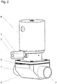
- the Figure 2 shows a diaphragm valve 4 with connections 7, an inlet and an outlet being provided.
- the diaphragm valve has a diaphragm 5 which is moved in the direction of the drive axis by means of a pneumatic device 6.
- a system for monitoring the state of a diaphragm valve and its pneumatic device 1 is provided on the pneumatic device 6.
Landscapes
- Engineering & Computer Science (AREA)
- General Engineering & Computer Science (AREA)
- Mechanical Engineering (AREA)
- Fluid-Driven Valves (AREA)
- Indication Of The Valve Opening Or Closing Status (AREA)
Applications Claiming Priority (1)
| Application Number | Priority Date | Filing Date | Title |
|---|---|---|---|
| DE102020101178.4A DE102020101178A1 (de) | 2020-01-20 | 2020-01-20 | System zur Zustandsüberwachung |
Publications (3)
| Publication Number | Publication Date |
|---|---|
| EP3851713A1 true EP3851713A1 (fr) | 2021-07-21 |
| EP3851713C0 EP3851713C0 (fr) | 2025-02-26 |
| EP3851713B1 EP3851713B1 (fr) | 2025-02-26 |
Family
ID=74186583
Family Applications (1)
| Application Number | Title | Priority Date | Filing Date |
|---|---|---|---|
| EP21152001.0A Active EP3851713B1 (fr) | 2020-01-20 | 2021-01-18 | Système de surveillance de l'état |
Country Status (2)
| Country | Link |
|---|---|
| EP (1) | EP3851713B1 (fr) |
| DE (1) | DE102020101178A1 (fr) |
Families Citing this family (1)
| Publication number | Priority date | Publication date | Assignee | Title |
|---|---|---|---|---|
| DE102022109948A1 (de) | 2022-04-25 | 2023-10-26 | Ifm Electronic Gmbh | Batteriebetriebener Schwingungssensor für die Automatisierungstechnik |
Citations (10)
| Publication number | Priority date | Publication date | Assignee | Title |
|---|---|---|---|---|
| EP0637713A1 (fr) * | 1993-08-05 | 1995-02-08 | Honeywell Ag | Système de diagnostic pour des soupapes de réglage et d'arrêt |
| US20050092079A1 (en) * | 2003-10-03 | 2005-05-05 | Ales Richard A. | Diaphragm monitoring for flow control devices |
| EP1726855A2 (fr) * | 2005-05-25 | 2006-11-29 | Big Dutchman (Skandinavien) A/S | Valve pour produits alimentaires avec une sonde de fuite intégrée |
| DE102014205117A1 (de) | 2014-03-19 | 2015-09-24 | Gemü Gebr. Müller Apparatebau Gmbh & Co. Kommanditgesellschaft | Membran und Verfahren zu deren Herstellung |
| DE102015210208A1 (de) | 2015-06-02 | 2016-12-08 | Gemü Gebr. Müller Apparatebau Gmbh & Co. Kommanditgesellschaft | Verfahren zum Ermitteln einer Zustandsgröße einer Ventilmembran eines elektronisch gesteuerten und motorisch angetriebenen Membranventils, sowie Membranventilsystem |
| DE102015210210A1 (de) | 2015-06-02 | 2016-12-08 | Gemü Gebr. Müller Apparatebau Gmbh & Co. Kommanditgesellschaft | Verfahren zur Diagnose eines Membranventils, sowie Diagnosesystem für ein Membranventil |
| DE102015219273A1 (de) * | 2015-10-06 | 2017-04-06 | Festo Ag & Co. Kg | Membraneinrichtung |
| EP3263963A1 (fr) * | 2016-06-29 | 2018-01-03 | CKD Corporation | Soupape de régulation de fluide avec capteur |
| EP2984533B1 (fr) | 2013-04-09 | 2018-08-01 | Fisher Controls International Llc | Actionneur intelligent et procédé de surveillance de l'état et de l'intégrité de l'actionneur |
| WO2020012828A1 (fr) * | 2018-07-09 | 2020-01-16 | 株式会社フジキン | Dispositif de régulation de fluide |
Family Cites Families (1)
| Publication number | Priority date | Publication date | Assignee | Title |
|---|---|---|---|---|
| US10466720B2 (en) * | 2013-08-09 | 2019-11-05 | Fisher Controls International Llc | Providing diagnostic and/or prognostic capabilities in a process control system |
-
2020
- 2020-01-20 DE DE102020101178.4A patent/DE102020101178A1/de active Pending
-
2021
- 2021-01-18 EP EP21152001.0A patent/EP3851713B1/fr active Active
Patent Citations (10)
| Publication number | Priority date | Publication date | Assignee | Title |
|---|---|---|---|---|
| EP0637713A1 (fr) * | 1993-08-05 | 1995-02-08 | Honeywell Ag | Système de diagnostic pour des soupapes de réglage et d'arrêt |
| US20050092079A1 (en) * | 2003-10-03 | 2005-05-05 | Ales Richard A. | Diaphragm monitoring for flow control devices |
| EP1726855A2 (fr) * | 2005-05-25 | 2006-11-29 | Big Dutchman (Skandinavien) A/S | Valve pour produits alimentaires avec une sonde de fuite intégrée |
| EP2984533B1 (fr) | 2013-04-09 | 2018-08-01 | Fisher Controls International Llc | Actionneur intelligent et procédé de surveillance de l'état et de l'intégrité de l'actionneur |
| DE102014205117A1 (de) | 2014-03-19 | 2015-09-24 | Gemü Gebr. Müller Apparatebau Gmbh & Co. Kommanditgesellschaft | Membran und Verfahren zu deren Herstellung |
| DE102015210208A1 (de) | 2015-06-02 | 2016-12-08 | Gemü Gebr. Müller Apparatebau Gmbh & Co. Kommanditgesellschaft | Verfahren zum Ermitteln einer Zustandsgröße einer Ventilmembran eines elektronisch gesteuerten und motorisch angetriebenen Membranventils, sowie Membranventilsystem |
| DE102015210210A1 (de) | 2015-06-02 | 2016-12-08 | Gemü Gebr. Müller Apparatebau Gmbh & Co. Kommanditgesellschaft | Verfahren zur Diagnose eines Membranventils, sowie Diagnosesystem für ein Membranventil |
| DE102015219273A1 (de) * | 2015-10-06 | 2017-04-06 | Festo Ag & Co. Kg | Membraneinrichtung |
| EP3263963A1 (fr) * | 2016-06-29 | 2018-01-03 | CKD Corporation | Soupape de régulation de fluide avec capteur |
| WO2020012828A1 (fr) * | 2018-07-09 | 2020-01-16 | 株式会社フジキン | Dispositif de régulation de fluide |
Also Published As
| Publication number | Publication date |
|---|---|
| EP3851713C0 (fr) | 2025-02-26 |
| EP3851713B1 (fr) | 2025-02-26 |
| DE102020101178A1 (de) | 2021-07-22 |
Similar Documents
| Publication | Publication Date | Title |
|---|---|---|
| EP1812718B1 (fr) | Systeme de diagnostic pour au moins un ensemble soupape-actionneur pneumatique | |
| EP0643814B1 (fr) | Procede et dispositif visant a verifier une garniture actionnee par un milieu | |
| EP3546763B1 (fr) | Détection des états de maintenance de vannes | |
| WO2019002490A1 (fr) | Soupape à dépression comprenant un capteur de pression | |
| EP3074680B1 (fr) | Soupape | |
| DE102007045529A1 (de) | Diagnosesystem und Diagnoseverfahren für ein Ventil, insbesondere ein Schließventil oder ein Regelventil | |
| DE102015210210A1 (de) | Verfahren zur Diagnose eines Membranventils, sowie Diagnosesystem für ein Membranventil | |
| DE102008062290A1 (de) | Verfahren zur Diagnose des Verschleißzustandes einer Ventilanordnung zur Steuerung eines Prozessmediumflusses | |
| DE102008062289A1 (de) | Verfahren zur weg- und drucksensorischen Verschleißzustandsermittlung einer Ventilmechanik sowie eine solche nutzende Ventilanordnung | |
| WO2014095245A1 (fr) | Procédé et dispositif de détermination d'un état d'un capteur de mesure intégré dans un réservoir de processus | |
| DE102012016295A1 (de) | Vorrichtung und Verfahren zum Quantifizieren eines Leckagedurchflusses an einem Stellgerät | |
| DE102008058208B4 (de) | Stellgerät und Verfahren zur Überprüfung der korrekten Funktionsfähigkeit eines Faltenbalges eines Stellgerätes | |
| EP3575909B1 (fr) | Procédé de surveillance d'une pluralité de systèmes mécaniques | |
| EP3851713B1 (fr) | Système de surveillance de l'état | |
| EP2699806A1 (fr) | Positionneur électropneumatique | |
| DE102012112174A1 (de) | Vorrichtung und Verfahren zur Überprüfung der Dichtheit einer Komponente einer Getränkeabfüllanlage | |
| EP2053290A2 (fr) | Procédé de détermination de l'état par rapport à l'usure et/ou au besoin d'entretien d'armatures de processus automatiques actionnées de manière pneumatique | |
| DE102018114710A1 (de) | Erkennen mangelhafter Sitz-Integrität bei einem Stellventil | |
| EP1443219A1 (fr) | Méthode et dispositif pour tester un actionneur pneumatique | |
| DE202004020347U1 (de) | Pneumatischer Schwenkantrieb zum Stellen eines Stellorgans, wie eines Ventils | |
| EP3021954A1 (fr) | Détection d'un processus de nettoyage d'une installation comprenant localement des filtres décalés les uns par rapport aux autres | |
| EP3851715A1 (fr) | Système de fonctionnement d'un dispositif pneumatique | |
| EP3851716B1 (fr) | Procédé de vérification de l'état d'usure d'une membrane | |
| EP4600494B1 (fr) | Pompe à membrane commandée par capteur | |
| DE102019210600B4 (de) | Diagnoseeinrichtung, Reglervorrichtung, fluidisches System und Verfahren zur Diagnose von Druckfluid-Leckage |
Legal Events
| Date | Code | Title | Description |
|---|---|---|---|
| PUAI | Public reference made under article 153(3) epc to a published international application that has entered the european phase |
Free format text: ORIGINAL CODE: 0009012 |
|
| STAA | Information on the status of an ep patent application or granted ep patent |
Free format text: STATUS: THE APPLICATION HAS BEEN PUBLISHED |
|
| AK | Designated contracting states |
Kind code of ref document: A1 Designated state(s): AL AT BE BG CH CY CZ DE DK EE ES FI FR GB GR HR HU IE IS IT LI LT LU LV MC MK MT NL NO PL PT RO RS SE SI SK SM TR |
|
| STAA | Information on the status of an ep patent application or granted ep patent |
Free format text: STATUS: REQUEST FOR EXAMINATION WAS MADE |
|
| 17P | Request for examination filed |
Effective date: 20211221 |
|
| STAA | Information on the status of an ep patent application or granted ep patent |
Free format text: STATUS: EXAMINATION IS IN PROGRESS |
|
| 17Q | First examination report despatched |
Effective date: 20230428 |
|
| GRAP | Despatch of communication of intention to grant a patent |
Free format text: ORIGINAL CODE: EPIDOSNIGR1 |
|
| STAA | Information on the status of an ep patent application or granted ep patent |
Free format text: STATUS: GRANT OF PATENT IS INTENDED |
|
| INTG | Intention to grant announced |
Effective date: 20240528 |
|
| GRAJ | Information related to disapproval of communication of intention to grant by the applicant or resumption of examination proceedings by the epo deleted |
Free format text: ORIGINAL CODE: EPIDOSDIGR1 |
|
| STAA | Information on the status of an ep patent application or granted ep patent |
Free format text: STATUS: EXAMINATION IS IN PROGRESS |
|
| GRAP | Despatch of communication of intention to grant a patent |
Free format text: ORIGINAL CODE: EPIDOSNIGR1 |
|
| STAA | Information on the status of an ep patent application or granted ep patent |
Free format text: STATUS: GRANT OF PATENT IS INTENDED |
|
| INTC | Intention to grant announced (deleted) | ||
| INTG | Intention to grant announced |
Effective date: 20241008 |
|
| GRAJ | Information related to disapproval of communication of intention to grant by the applicant or resumption of examination proceedings by the epo deleted |
Free format text: ORIGINAL CODE: EPIDOSDIGR1 |
|
| STAA | Information on the status of an ep patent application or granted ep patent |
Free format text: STATUS: EXAMINATION IS IN PROGRESS |
|
| GRAS | Grant fee paid |
Free format text: ORIGINAL CODE: EPIDOSNIGR3 |
|
| STAA | Information on the status of an ep patent application or granted ep patent |
Free format text: STATUS: GRANT OF PATENT IS INTENDED |
|
| GRAP | Despatch of communication of intention to grant a patent |
Free format text: ORIGINAL CODE: EPIDOSNIGR1 |
|
| GRAA | (expected) grant |
Free format text: ORIGINAL CODE: 0009210 |
|
| STAA | Information on the status of an ep patent application or granted ep patent |
Free format text: STATUS: THE PATENT HAS BEEN GRANTED |
|
| INTG | Intention to grant announced |
Effective date: 20250113 |
|
| AK | Designated contracting states |
Kind code of ref document: B1 Designated state(s): AL AT BE BG CH CY CZ DE DK EE ES FI FR GB GR HR HU IE IS IT LI LT LU LV MC MK MT NL NO PL PT RO RS SE SI SK SM TR |
|
| REG | Reference to a national code |
Ref country code: GB Ref legal event code: FG4D Free format text: NOT ENGLISH |
|
| REG | Reference to a national code |
Ref country code: CH Ref legal event code: EP |
|
| REG | Reference to a national code |
Ref country code: DE Ref legal event code: R096 Ref document number: 502021006735 Country of ref document: DE |
|
| REG | Reference to a national code |
Ref country code: IE Ref legal event code: FG4D Free format text: LANGUAGE OF EP DOCUMENT: GERMAN |
|
| U01 | Request for unitary effect filed |
Effective date: 20250226 |
|
| U07 | Unitary effect registered |
Designated state(s): AT BE BG DE DK EE FI FR IT LT LU LV MT NL PT RO SE SI Effective date: 20250306 |
|
| PG25 | Lapsed in a contracting state [announced via postgrant information from national office to epo] |
Ref country code: RS Free format text: LAPSE BECAUSE OF FAILURE TO SUBMIT A TRANSLATION OF THE DESCRIPTION OR TO PAY THE FEE WITHIN THE PRESCRIBED TIME-LIMIT Effective date: 20250526 |
|
| PG25 | Lapsed in a contracting state [announced via postgrant information from national office to epo] |
Ref country code: PL Free format text: LAPSE BECAUSE OF FAILURE TO SUBMIT A TRANSLATION OF THE DESCRIPTION OR TO PAY THE FEE WITHIN THE PRESCRIBED TIME-LIMIT Effective date: 20250226 |
|
| PG25 | Lapsed in a contracting state [announced via postgrant information from national office to epo] |
Ref country code: ES Free format text: LAPSE BECAUSE OF FAILURE TO SUBMIT A TRANSLATION OF THE DESCRIPTION OR TO PAY THE FEE WITHIN THE PRESCRIBED TIME-LIMIT Effective date: 20250226 |
|
| PG25 | Lapsed in a contracting state [announced via postgrant information from national office to epo] |
Ref country code: IS Free format text: LAPSE BECAUSE OF FAILURE TO SUBMIT A TRANSLATION OF THE DESCRIPTION OR TO PAY THE FEE WITHIN THE PRESCRIBED TIME-LIMIT Effective date: 20250626 Ref country code: NO Free format text: LAPSE BECAUSE OF FAILURE TO SUBMIT A TRANSLATION OF THE DESCRIPTION OR TO PAY THE FEE WITHIN THE PRESCRIBED TIME-LIMIT Effective date: 20250526 |
|
| PG25 | Lapsed in a contracting state [announced via postgrant information from national office to epo] |
Ref country code: HR Free format text: LAPSE BECAUSE OF FAILURE TO SUBMIT A TRANSLATION OF THE DESCRIPTION OR TO PAY THE FEE WITHIN THE PRESCRIBED TIME-LIMIT Effective date: 20250226 |
|
| PG25 | Lapsed in a contracting state [announced via postgrant information from national office to epo] |
Ref country code: GR Free format text: LAPSE BECAUSE OF FAILURE TO SUBMIT A TRANSLATION OF THE DESCRIPTION OR TO PAY THE FEE WITHIN THE PRESCRIBED TIME-LIMIT Effective date: 20250527 |
|
| PG25 | Lapsed in a contracting state [announced via postgrant information from national office to epo] |
Ref country code: SM Free format text: LAPSE BECAUSE OF FAILURE TO SUBMIT A TRANSLATION OF THE DESCRIPTION OR TO PAY THE FEE WITHIN THE PRESCRIBED TIME-LIMIT Effective date: 20250226 |
|
| PG25 | Lapsed in a contracting state [announced via postgrant information from national office to epo] |
Ref country code: CZ Free format text: LAPSE BECAUSE OF FAILURE TO SUBMIT A TRANSLATION OF THE DESCRIPTION OR TO PAY THE FEE WITHIN THE PRESCRIBED TIME-LIMIT Effective date: 20250226 |
|
| PG25 | Lapsed in a contracting state [announced via postgrant information from national office to epo] |
Ref country code: SK Free format text: LAPSE BECAUSE OF FAILURE TO SUBMIT A TRANSLATION OF THE DESCRIPTION OR TO PAY THE FEE WITHIN THE PRESCRIBED TIME-LIMIT Effective date: 20250226 |
|
| PLBE | No opposition filed within time limit |
Free format text: ORIGINAL CODE: 0009261 |
|
| STAA | Information on the status of an ep patent application or granted ep patent |
Free format text: STATUS: NO OPPOSITION FILED WITHIN TIME LIMIT |
|
| REG | Reference to a national code |
Ref country code: CH Ref legal event code: L10 Free format text: ST27 STATUS EVENT CODE: U-0-0-L10-L00 (AS PROVIDED BY THE NATIONAL OFFICE) Effective date: 20260107 |
|
| REG | Reference to a national code |
Ref country code: CH Ref legal event code: U11 Free format text: ST27 STATUS EVENT CODE: U-0-0-U10-U11 (AS PROVIDED BY THE NATIONAL OFFICE) Effective date: 20260201 |
|
| 26N | No opposition filed |
Effective date: 20251127 |
|
| U20 | Renewal fee for the european patent with unitary effect paid |
Year of fee payment: 6 Effective date: 20260121 |