EP3851736B1 - Lampe pratique à installer et module d'applications diverses l'utilisant - Google Patents
Lampe pratique à installer et module d'applications diverses l'utilisant Download PDFInfo
- Publication number
- EP3851736B1 EP3851736B1 EP20157993.5A EP20157993A EP3851736B1 EP 3851736 B1 EP3851736 B1 EP 3851736B1 EP 20157993 A EP20157993 A EP 20157993A EP 3851736 B1 EP3851736 B1 EP 3851736B1
- Authority
- EP
- European Patent Office
- Prior art keywords
- glare
- lamp panel
- application module
- diverse application
- assembly
- Prior art date
- Legal status (The legal status is an assumption and is not a legal conclusion. Google has not performed a legal analysis and makes no representation as to the accuracy of the status listed.)
- Active
Links
Images




Classifications
-
- F—MECHANICAL ENGINEERING; LIGHTING; HEATING; WEAPONS; BLASTING
- F21—LIGHTING
- F21S—NON-PORTABLE LIGHTING DEVICES; SYSTEMS THEREOF; VEHICLE LIGHTING DEVICES SPECIALLY ADAPTED FOR VEHICLE EXTERIORS
- F21S4/00—Lighting devices or systems using a string or strip of light sources
- F21S4/20—Lighting devices or systems using a string or strip of light sources with light sources held by or within elongate supports
- F21S4/28—Lighting devices or systems using a string or strip of light sources with light sources held by or within elongate supports rigid, e.g. LED bars
-
- F—MECHANICAL ENGINEERING; LIGHTING; HEATING; WEAPONS; BLASTING
- F21—LIGHTING
- F21S—NON-PORTABLE LIGHTING DEVICES; SYSTEMS THEREOF; VEHICLE LIGHTING DEVICES SPECIALLY ADAPTED FOR VEHICLE EXTERIORS
- F21S2/00—Systems of lighting devices, not provided for in main groups F21S4/00 - F21S10/00 or F21S19/00, e.g. of modular construction
- F21S2/005—Systems of lighting devices, not provided for in main groups F21S4/00 - F21S10/00 or F21S19/00, e.g. of modular construction of modular construction
-
- F—MECHANICAL ENGINEERING; LIGHTING; HEATING; WEAPONS; BLASTING
- F21—LIGHTING
- F21V—FUNCTIONAL FEATURES OR DETAILS OF LIGHTING DEVICES OR SYSTEMS THEREOF; STRUCTURAL COMBINATIONS OF LIGHTING DEVICES WITH OTHER ARTICLES, NOT OTHERWISE PROVIDED FOR
- F21V13/00—Producing particular characteristics or distribution of the light emitted by means of a combination of elements specified in two or more of main groups F21V1/00 - F21V11/00
- F21V13/02—Combinations of only two kinds of elements
- F21V13/04—Combinations of only two kinds of elements the elements being reflectors and refractors
-
- F—MECHANICAL ENGINEERING; LIGHTING; HEATING; WEAPONS; BLASTING
- F21—LIGHTING
- F21V—FUNCTIONAL FEATURES OR DETAILS OF LIGHTING DEVICES OR SYSTEMS THEREOF; STRUCTURAL COMBINATIONS OF LIGHTING DEVICES WITH OTHER ARTICLES, NOT OTHERWISE PROVIDED FOR
- F21V15/00—Protecting lighting devices from damage
- F21V15/01—Housings, e.g. material or assembling of housing parts
- F21V15/015—Devices for covering joints between adjacent lighting devices; End coverings
-
- F—MECHANICAL ENGINEERING; LIGHTING; HEATING; WEAPONS; BLASTING
- F21—LIGHTING
- F21V—FUNCTIONAL FEATURES OR DETAILS OF LIGHTING DEVICES OR SYSTEMS THEREOF; STRUCTURAL COMBINATIONS OF LIGHTING DEVICES WITH OTHER ARTICLES, NOT OTHERWISE PROVIDED FOR
- F21V17/00—Fastening of component parts of lighting devices, e.g. shades, globes, refractors, reflectors, filters, screens, grids or protective cages
- F21V17/10—Fastening of component parts of lighting devices, e.g. shades, globes, refractors, reflectors, filters, screens, grids or protective cages characterised by specific fastening means or way of fastening
-
- F—MECHANICAL ENGINEERING; LIGHTING; HEATING; WEAPONS; BLASTING
- F21—LIGHTING
- F21V—FUNCTIONAL FEATURES OR DETAILS OF LIGHTING DEVICES OR SYSTEMS THEREOF; STRUCTURAL COMBINATIONS OF LIGHTING DEVICES WITH OTHER ARTICLES, NOT OTHERWISE PROVIDED FOR
- F21V17/00—Fastening of component parts of lighting devices, e.g. shades, globes, refractors, reflectors, filters, screens, grids or protective cages
- F21V17/10—Fastening of component parts of lighting devices, e.g. shades, globes, refractors, reflectors, filters, screens, grids or protective cages characterised by specific fastening means or way of fastening
- F21V17/12—Fastening of component parts of lighting devices, e.g. shades, globes, refractors, reflectors, filters, screens, grids or protective cages characterised by specific fastening means or way of fastening by screwing
-
- F—MECHANICAL ENGINEERING; LIGHTING; HEATING; WEAPONS; BLASTING
- F21—LIGHTING
- F21V—FUNCTIONAL FEATURES OR DETAILS OF LIGHTING DEVICES OR SYSTEMS THEREOF; STRUCTURAL COMBINATIONS OF LIGHTING DEVICES WITH OTHER ARTICLES, NOT OTHERWISE PROVIDED FOR
- F21V17/00—Fastening of component parts of lighting devices, e.g. shades, globes, refractors, reflectors, filters, screens, grids or protective cages
- F21V17/10—Fastening of component parts of lighting devices, e.g. shades, globes, refractors, reflectors, filters, screens, grids or protective cages characterised by specific fastening means or way of fastening
- F21V17/16—Fastening of component parts of lighting devices, e.g. shades, globes, refractors, reflectors, filters, screens, grids or protective cages characterised by specific fastening means or way of fastening by deformation of parts; Snap action mounting
- F21V17/164—Fastening of component parts of lighting devices, e.g. shades, globes, refractors, reflectors, filters, screens, grids or protective cages characterised by specific fastening means or way of fastening by deformation of parts; Snap action mounting the parts being subjected to bending, e.g. snap joints
-
- F—MECHANICAL ENGINEERING; LIGHTING; HEATING; WEAPONS; BLASTING
- F21—LIGHTING
- F21V—FUNCTIONAL FEATURES OR DETAILS OF LIGHTING DEVICES OR SYSTEMS THEREOF; STRUCTURAL COMBINATIONS OF LIGHTING DEVICES WITH OTHER ARTICLES, NOT OTHERWISE PROVIDED FOR
- F21V19/00—Fastening of light sources or lamp holders
- F21V19/001—Fastening of light sources or lamp holders the light sources being semiconductors devices, e.g. LEDs
-
- F—MECHANICAL ENGINEERING; LIGHTING; HEATING; WEAPONS; BLASTING
- F21—LIGHTING
- F21V—FUNCTIONAL FEATURES OR DETAILS OF LIGHTING DEVICES OR SYSTEMS THEREOF; STRUCTURAL COMBINATIONS OF LIGHTING DEVICES WITH OTHER ARTICLES, NOT OTHERWISE PROVIDED FOR
- F21V21/00—Supporting, suspending, or attaching arrangements for lighting devices; Hand grips
- F21V21/002—Supporting, suspending, or attaching arrangements for lighting devices; Hand grips making direct electrical contact, e.g. by piercing
-
- F—MECHANICAL ENGINEERING; LIGHTING; HEATING; WEAPONS; BLASTING
- F21—LIGHTING
- F21V—FUNCTIONAL FEATURES OR DETAILS OF LIGHTING DEVICES OR SYSTEMS THEREOF; STRUCTURAL COMBINATIONS OF LIGHTING DEVICES WITH OTHER ARTICLES, NOT OTHERWISE PROVIDED FOR
- F21V23/00—Arrangement of electric circuit elements in or on lighting devices
- F21V23/003—Arrangement of electric circuit elements in or on lighting devices the elements being electronics drivers or controllers for operating the light source, e.g. for a LED array
-
- F—MECHANICAL ENGINEERING; LIGHTING; HEATING; WEAPONS; BLASTING
- F21—LIGHTING
- F21V—FUNCTIONAL FEATURES OR DETAILS OF LIGHTING DEVICES OR SYSTEMS THEREOF; STRUCTURAL COMBINATIONS OF LIGHTING DEVICES WITH OTHER ARTICLES, NOT OTHERWISE PROVIDED FOR
- F21V23/00—Arrangement of electric circuit elements in or on lighting devices
- F21V23/06—Arrangement of electric circuit elements in or on lighting devices the elements being coupling devices, e.g. connectors
-
- F—MECHANICAL ENGINEERING; LIGHTING; HEATING; WEAPONS; BLASTING
- F21—LIGHTING
- F21V—FUNCTIONAL FEATURES OR DETAILS OF LIGHTING DEVICES OR SYSTEMS THEREOF; STRUCTURAL COMBINATIONS OF LIGHTING DEVICES WITH OTHER ARTICLES, NOT OTHERWISE PROVIDED FOR
- F21V5/00—Refractors for light sources
- F21V5/007—Array of lenses or refractors for a cluster of light sources, e.g. for arrangement of multiple light sources in one plane
-
- F—MECHANICAL ENGINEERING; LIGHTING; HEATING; WEAPONS; BLASTING
- F21—LIGHTING
- F21V—FUNCTIONAL FEATURES OR DETAILS OF LIGHTING DEVICES OR SYSTEMS THEREOF; STRUCTURAL COMBINATIONS OF LIGHTING DEVICES WITH OTHER ARTICLES, NOT OTHERWISE PROVIDED FOR
- F21V5/00—Refractors for light sources
- F21V5/04—Refractors for light sources of lens shape
-
- F—MECHANICAL ENGINEERING; LIGHTING; HEATING; WEAPONS; BLASTING
- F21—LIGHTING
- F21V—FUNCTIONAL FEATURES OR DETAILS OF LIGHTING DEVICES OR SYSTEMS THEREOF; STRUCTURAL COMBINATIONS OF LIGHTING DEVICES WITH OTHER ARTICLES, NOT OTHERWISE PROVIDED FOR
- F21V7/00—Reflectors for light sources
-
- F—MECHANICAL ENGINEERING; LIGHTING; HEATING; WEAPONS; BLASTING
- F21—LIGHTING
- F21Y—INDEXING SCHEME ASSOCIATED WITH SUBCLASSES F21K, F21L, F21S and F21V, RELATING TO THE FORM OR THE KIND OF THE LIGHT SOURCES OR OF THE COLOUR OF THE LIGHT EMITTED
- F21Y2103/00—Elongate light sources, e.g. fluorescent tubes
- F21Y2103/10—Elongate light sources, e.g. fluorescent tubes comprising a linear array of point-like light-generating elements
-
- F—MECHANICAL ENGINEERING; LIGHTING; HEATING; WEAPONS; BLASTING
- F21—LIGHTING
- F21Y—INDEXING SCHEME ASSOCIATED WITH SUBCLASSES F21K, F21L, F21S and F21V, RELATING TO THE FORM OR THE KIND OF THE LIGHT SOURCES OR OF THE COLOUR OF THE LIGHT EMITTED
- F21Y2115/00—Light-generating elements of semiconductor light sources
- F21Y2115/10—Light-emitting diodes [LED]
Definitions
- the invention relates to the field of application modules, in particular to a lamp that is convenient to install and a diverse application module using the same.
- ZHAGA as an association of top LED manufacturers in the world, aims to realize the compatibility and interchangeability of optical engines through standardization and to facilitate the wide application of LED technologies hereby.
- the ZHAGA standard defines a stable design platform for lamp manufacturers by standardizing interfaces of the optical engines, so that a large quantity of products incompatible with optical engine products on the market are avoided, thus reducing the development cost of light source applications.
- CN109058845A discloses a shelf lamp capable of reducing a UGR value
- the shelf lamp comprises a radiator, a connecting seat is arranged in the middle of the radiator, a light source mounting groove is formed in the lower end of the connecting seat, an LED lamp belt is mounted in the light source mounting groove, a lens is further fixedly connected to the lower portion of the connecting seat, a light collecting groove is formed in the position, under the LED lamp belt, of the lens, a turn up for positioning a grating cover is arranged at the lower end of the radiator, the grating cover is further connected to the lower end of the lens, a storing groove for storing a grating plate of the grating cover is formed in the lower side of the lens, the two ends of the radiator are connected with plugs through screws, according to the shelf lamp capable of reducing the UGR value.
- CN201262345Y discloses a wall-washing lamp, a lamp body thereof comprises two side plates, a transverse plate and an integrated strip heat conducting section; and the transverse plate used for supporting an aluminum substrate of an LED bulb and the lamp body are integrated.
- US2016/053973A1 discloses a lighting system including an extrusion, a lighted strip, a control board, and a connector, the extrusion comprises a pair of side walls coupled by a connecting member, where the connecting member forms a first shelf for a lighted strip and a pair of flanges projecting from the side walls form a second shelf for a control board, the connector comprises a shell with an outer surface which is adapted to be coupled with the extrusion, and a pin which can be adapted to receive a wire adjacent a first end of the connector, the pin also including a curved contact plate which can be adapted to receive the lighted strip adjacent a second end of the connector.
- US2012/081899A1 discloses a method of designing a modular lighting system comprising determining a length of a lighting fixture, then selecting a plurality of LED modules from a selection of standardized sizes, and assembling the modules together with a fixture, so that the modules and the fixture combine to form the determined length, the selecting is done from a group comprising either a 10 inch, a 12 inch or a 4 inch LED module, the determining is in response to a building metric, also disclosed is a luminaire comprising a hub having a predetermined length; with LED modules, each having a different length, where the lengths of the hub and the modules combined form a standard length as generally used in the building and construction trades, by way of example, these standard lengths could be 12, 16 or 24 inches.
- the patent of invention aims to solve the following technical problems: the non-standardized sizes of application modules in the existing market cannot meet the European ZHAGA standards and lead to inconsistency of application modules of existing lamps, waste of raw materials and non-uniform lighting effects.
- a diverse application module comprising:plugs, a profile, an anti-glare assembly, and a lamp that is convenient to install and consists of a lamp panel and a plurality of integrated LED lamps fixed to the lamp panel, wherein a distance between centers of every two adjacent said integrated LED lamps range from 24.5mm to 25.5mm to make the plurality of integrated LED lamps adaptively installed on the lamp panel, wherein the anti-glare assembly is installed on a front side of the lamp panel, the profile is installed on a back side of the lamp panel, and the plugs are installed at two ends of the lamp panel, the profile, and the anti-glare assembly to fix the profile, the anti-glare assembly, and the lamp panel; characterized in that the anti-glare assembly is formed by a plurality of independent anti-glare parts connected into a whole, and each anti-glare part is one cup; the number of the integrated LED lamps equals to the cup number of the anti-glare assembly, where
- the distance between the centers of every two integrated LED lamps is set as 24.5mm, 25mm, or 25.5mm to meet the European ZHAGA standards.
- the number of the integrated LED lamps is 22, 46, 58, 70, or 94.
- the lamp panel is thin and rectangular on the whole, and the integrated LED lamps are uniformly distributed in the length direction of the lamp panel.
- the lamp panel is provided with a circuit to supply a current to the integrated LED lamps fixed to the lamp panel by means of tin soldering or bonding.
- Each plug includes a plug body and a conductive elastic sheet, wherein the plug body includes a connection protrusion and a first lug boss and is formed with grooves to make the two ends of the anti-glare assembly fixed to the two ends of the lamp panel.
- the grooves are located at the two ends of the anti-glare assembly and the two ends of the profile, and the anti-glare assembly is clamped in the grooves, so that a combination of the grooves, the anti-glare assembly, and the profile meets the ZHAGA standards.
- the length of the combination of the grooves, the anti-glare assembly, and the profile meets the ZHAGA standard
- the number of the integrated LED lamps and the cup number of the anti-glare assembly meet the ZHAGA standard.
- the height from the first lug boss to the bottom face of the plug ranges from 25.8mm to 26.2mm
- the width of the plug ranges from 36.8mm to 37.2mm
- the conductive elastic sheet is installed in one groove and is electrically connected to the lamp panel.
- the height from the first lug boss to the bottom face of the plug is defined as the height of the diverse application module
- the width of the plug is defined as the width of the diverse application module
- an electrical connector is arranged at each end of the lamp panel and is electrically connected to the conductive elastic sheet.
- the profile is connected to the anti-glare assembly to fix the lamp panel and is provided with a cross beam to bear the weights of the lamp panel and the anti-glare assembly.
- the profile is rectangular on the whole and allows the back side of the lamp panel to be clamped therein.
- one or two reinforcing rods are arranged in the profile.
- the two ends of the profile are clamped and fixed to the plugs through screws, buckles, or hooks.
- the reflector includes a reflection cup and a lens or is a combination of the reflection cup and the lens.
- the reflector is integrally designed to be integrally installed on the anti-glare shade.
- the anti-glare assembly performs optical processing on light emitted from LED lamps in the integrated LED lamps to make a UGR of the light less than 19.
- the diverse application module has a length ranging from 562mm to 566mm, from 1162mm to 1166mm, from 1462mm to 1466mm, from 1762mm to 1766mm, or from 2362mm to 2366mm according to the ZHAGA standards.
- the overall length of a product is set to range from 562mm to 566mm, from 1162mm to 1166mm, from 1462mm to 1466mm, from 1762mm to 1766mm, or from 2362mm to 2366mm to respectively meet the length requirements of a 0.6m module, a 1.2m module, a 1.5m module, a 1.8m module, and a 2.4m module in the European ZHAGA standard.
- the invention has the following beneficial effects: the sizes of lamps and application modules on the existing market are standardized to meet the European ZHAGA standards and to unify the sizes of profiles and lamp panels on the existing market, and material waste of the lamps and the application modules using the same is reduced.
- connection may refer to fixed connection, detachable connection, integral connection, mechanical connection, electrical connection, direct connection, indirect connection via a medium, internal communication of two elements, wireless connection, or wired connection.
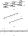
- Fig. 1 and Fig. 2 show a lamp convenient to install and a diverse application module using the same.
- the diverse application module comprises plugs 1, a profile 2, an anti-glare assembly, and a lamp panel 27, wherein the anti-glare assembly is installed on the front side of the lamp panel 27, the profile 2 is installed on the back side of the lamp panel 27, and the plugs 1 are installed at two ends of the lamp panel, the profile 2, and the anti-glare assembly to fix the profile 2, the anti-glare assembly, and the lamp panel.
- the lamp comprises the lamp panel 27 and a plurality of integrated LED lamps 3 fixed to the lamp panel 27, wherein each integrated LED lamp 3 is formed by four LED lamps 30, and the distance between centers of every two adjacent integrated LED lamps 3 is designed as 24.5mm, 24.8mm, 25mm, 25.2mm, 25.5mm, or the like to meet the European ZHAGA standard.
- the distance between every two adjacent anti-glare shades 23 and the distance between every two adjacent reflectors are designed as 24.5mm, 24.8mm, 25mm, 25.2mm, 25.5mm, or the like.
- the number of the integrated LED lamps 3 and the cup number of cups of the anti-glare assembly are respectively set as 22, 46, 58, 70, and 94 according to the 0.6m module, the 1.2m module, the 1.5m module, the 1.8m module, and the 2.4m module.
- the height from a first lug boss 8 to the bottom face of one plug 1 is defined as the height of the diverse application module, and the width of the plug 1 is defined as the width of the diverse application module.
- the height of the diverse application module is 25.8mm, 25.9mm, 26mm, 26.1mm, 26.2mm, or the like.
- the width of the diverse application module is 36.8mm, 36.9mm, 37mm, 37.1mm, 37.2mm, or the like.
- the diverse application module is, by length, the 0.6m module, the 1.2m module, the 1.5m module, the 1.8m module, or the 2.4m module as specified by the ZHAGA standard.
- the length of the 0.6m module is 562mm, 563mm, 563.5mm, 564mm, 565mm, 565.5mm, 566mm, or the like.
- the length of the 1.2m module is 1162mm, 1163mm, 1163.5mm, 1164mm, 1165mm, 1165.5mm, 1166mm, or the like.
- the length of the 1.5m module is 1462mm, 1463mm, 1463.5mm, 1464mm, 1465mm, 1465.5mm, 1466mm, or the like.
- the length of the 1.8m module is 1762mm, 1763mm, 1763.5mm, 1764mm, 1765mm, 1765.5mm, 1766mm, or the like.
- the length of the 2.4m module is 2362mm, 2363mm, 2363.5mm, 2364mm, 2365mm, 2365.5mm, 2366mm, or the like.
- the diverse application module has two ends supplied with power.
- each reflector is formed by a reflection cup 24 and a lens 25.
- the glare rating of light processed by the anti-glare assembly is 19, 18, 17, 16, 13, 10, 9, 4, or the like.
- electrical connectors are SMD terminals 4.
- two ends of the profile 2 are fixedly connected to the plugs through bolts 28.
- the diverse application module comprises plugs 1, a profile 2, an anti-glare shade 23, reflection cups 24, lenses 25, and a lamp panel 27, wherein the anti-glare shade 23, the reflection cups 24, and the lenses 25 are installed on the front side of the lamp panel 27 and have two ends clamped in grooves 12 in the plugs 1; the profile 2 is installed on the back side of the lamp panel 27 and has two ends clamped with the plugs 1; and two ends of the lamp panel 27 are inserted into the plugs 1 installed at the two ends of the lamp panel 27, the profile 2, the anti-glare shade 23, the reflection cups 24, and the lenses 25 to fix the profile 2, the anti-glare shade 23, the reflection cups 24, the lenses 25, and the lamp panel 27.
- a plurality of integrated LED lamps 3 are fixed to the lamp panel 27 by means of tin soldering and are linearly arrayed all over the lamp panel 27 which supplies power to the integrated LED lamps 3 through a printed circuit located on the lamp panel 27, each integrated LED lamp 3 includes four square LED lamps 30, and the two ends of the lamp panel 27 are narrowed to form connection ends respectively provided with a SMD terminal 4.
- each plug 1 includes a plug body 6 and conductive elastic sheets 5, wherein the conductive elastic sheets 5 penetrate through the plug body 6 to be connected to an electrical protrusion 7, the grooves 12 are formed in the side faces of the plug body 6, have the two ends of the anti-glare shade 23, the reflection cups 24, the lenses 25, and the lamp panel 27 fixed therein, and are located in the two ends of the anti-glare shade 23 and the two ends of the profile 2, the anti-glare shade 23 is clamped in the grooves 12, and the profile 2 abuts against the plug 1 to make the grooves 12 combined with the anti-glare shade 23 and the profile 2 to form an overall length; the number of the integrated LED lamps and the cup number of the anti-glare shade 23, the reflection cups 24, and the lenses 25 meet the ZHAGA standard; each conductive elastic sheet 5 includes an upper insertion part 9 and a lower elastic sheet 13, wherein the insertion part
- the profile 2 includes side walls 14, a first cross beam 16, and a second cross beam 15, wherein first projections 15 and second projections 17 are horizontally symmetrically distributed on the side walls 14, and the first projections 15 are clamped with the anti-glare shade 23 to position and fix the anti-glare shade 23;
- the first cross beam 16 includes a support platform 18 having a width consistent with the width of the lamp panel 27, and a first protrusion point 19 and a second protrusion point 20 are arranged at two ends of the support platform 18 to jointly support the lamp panel 27; and two reinforcing rods 21 are arranged between the second cross beam 15 and the first cross beam 16 to reinforce the profile 2.
- Each plug 1 is formed with two bolt holes 29, the profile is formed with two ear holes 22, and bolts 28 penetrate through the bolt holes 29 and the ear holes 22 to fix the profile 2 and the plugs 1 together.
- the anti-glare assembly includes the anti-glare shade 23, the reflection cups 24, and the lenses 25, wherein the lenses 25 are installed on the reflection cups 24 which are installed on an installation part of the anti-glare shade 23, and the reflection cups 24 and the lenses 25 are respectively integrally designed.
- the reflection cups 24 are connected to form a single-row integral strip, and the lenses 25 are connected to form a single-row integral strip; and the reflection cups 24 and the lenses 25 are both clamped on the strip-shaped anti-glare shade 23.
- the anti-glare shade 23, the reflection cups 24, and the lenses 25 refract and reflect light emitted from the LED lamps 30, so that the UGR of the light is 18.
- the anti-glare shade 23 has the two ends clamped in the grooves 12 in the plugs 1, and is clamped by means of the first projections 15 and the second projections 7 on the profile 2.
- the distance between centers of every two adjacent integrated LED lamps is 24.5mm
- the application module has a length of 564mm, a width of 37mm, and a height of 26mm
- the number of the integrated LED lamps 3 is 22.
- Embodiment 1 only the size of the diverse application module is changed as follows in this embodiment: as shown in Fig. 14 and Fig. 15 , the distance between the centers of every two adjacent integrated LED lamps 3 is 25mm, the application module has a length of 564mm, a width of 37mm, and a height of 26mm, and the number of the integrated LED lamps 3 is 22.
- Embodiment 2 only the size of the diverse application module is changed as follows in this embodiment: as shown in Fig. 16 and Fig. 17 , the distance between the centers of every two adjacent integrated LED lamps 3 is 25.5mm, the application module has a length of 564mm, a width of 37mm, and a height of 26mm, and the number of the integrated LED lamps 3 is 22.
- Embodiment 1 the influence of changes to the distance between the integrated LED lamps 3 on the technical effect of a 0.6m module is the same as that of the changes to the distance between the integrated LED lamps 3 on the technical effect of a 1.2m module, a 1.5m module, a 1.8m module, and a 2.4m module.
- a 1.2m module the 1.5m module, the 1.8m module, and the 2.4m module are no longer illustrated.
Landscapes
- Engineering & Computer Science (AREA)
- General Engineering & Computer Science (AREA)
- Microelectronics & Electronic Packaging (AREA)
- Non-Portable Lighting Devices Or Systems Thereof (AREA)
- Arrangement Of Elements, Cooling, Sealing, Or The Like Of Lighting Devices (AREA)
Claims (9)
- Module à applications diverses, comprenant :des fiches (1),un profilé (2),un assemblage anti-éblouissement, etune lampe qui est pratique à installer et consistant d'un panneau à lampes (27) et d'une pluralité de lampes à DEL intégrées (3) fixées au panneau à lampes (27), une distance entre des centres de chaque paire des dites lampes à DEL intégrées (3) adjacentes étant comprise entre 24,5 mm et 25,5 mm pour faire en sorte que la pluralité de lampes à DEL intégrées (3) soient installées de manière adaptative sur le panneau à lampes (27),l'assemblage anti-éblouissement étant installé sur une face avant du panneau à lampes (27), le profilé (2) étant installé sur un côté arrière du panneau à lampes (27) et les fiches (1) étant installées sur deux extrémités du panneau à lampes (27), du profilé (2) de l'assemblage anti-éblouissement afin de fixer le profilé (2), l'assemblage anti-éblouissement et le panneau à lampes (27), caractérisé en ce quel'assemblage anti-éblouissement est formé par une pluralité de parties anti-éblouissement indépendantes connectées en un ensemble, et chaque partie anti-éblouissement est une coupelle ; le nombre de lampes à DEL intégrées (3) est égal au nombre de coupelles de l'assemblage anti-éblouissement, chacune des coupelles de l'assemblage anti-éblouissement incluant un store anti-éblouissement (23) et un réflecteur, le store anti-éblouissement (23) incluant une partie d'installation permettant au réflecteur d'être installé dessus de manière détachable, et le panneau à lampes (27) et la partie d'installation étant installés de manière détachable afin d'assurer que le chacun des centres des lampes à DEL intégrées (3) correspond au centre du réflecteur correspondant, respectivement.
- Module à applications diverses selon la revendication 1, dans lequel chaque réflecteur inclut une coupelle de réflexion et une lentille ou est une combinaison de la coupelle de réflexion (24) et de la lentille (25).
- Module à applications diverses selon la revendication 1, dans lequel la distance entre les centres de chaque paire des dites lampes à DEL intégrées (3) adjacentes est de 24,5 mm, 25 mm, ou 25,5 mm.
- Module à applications diverses selon la revendication 1, dans lequel des rainures (12) sont formées dans des corps de fiche (6), et les deux extrémités de l'assemblage anti-éblouissement sont connectées de manière fixe aux deux extrémités du panneau à lampes (27) par le biais des rainures (12).
- Module à applications diverses selon la revendication 4, dans lequel chaque dite fiche (1) inclut un dit corps de fiche (6) et une feuille élastique conductrice (5), le corps de fiche (6) incluant une saillie de connexion (7) et un premier bossage (8), une hauteur du premier bossage (8) à une face inférieure de la fiche (1) étant comprise entre 25,8 mm et 26,2 mm, une largeur de la fiche (1) étant comprise entre 36,8 mm et 37,2 mm, et la feuille élastique conductrice (5) étant installée dans une dite rainure (12) et étant connectée électriquement au panneau à lampes (27).
- Module à applications diverses selon la revendication 4, dans lequel un connecteur électrique est disposé sur le panneau à lampes (27) et est connecté électriquement à la feuille élastique conductrice (5).
- Module à applications diverses selon la revendication 1, dans lequel le profilé (2) est connecté à l'assemblage anti-éblouissement pour fixer le panneau à lampes (27) et est équipé d'une première traverse (15) pour soutenir des poids du panneau à lampes (27) et l'assemblage anti-éblouissement
- Module à applications diverses selon la revendication 1, dans lequel le réflecteur est conçu pour être installé intégralement sur le store anti-éblouissement (23).
- Module à applications diverses selon la revendication 1, dans lequel le module à applications diverses a une longueur comprise entre 562 mm et 566 mm, entre 1162 mm et 1166 mm, entre 1462 mm et 1466 mm, entre 1762 mm et 1766 mm, ou entre 2362 mm et 2366 mm.
Applications Claiming Priority (1)
| Application Number | Priority Date | Filing Date | Title |
|---|---|---|---|
| CN202010052397.4A CN110985915A (zh) | 2020-01-17 | 2020-01-17 | 一种便捷安装灯具及其多元化应用模组 |
Publications (3)
| Publication Number | Publication Date |
|---|---|
| EP3851736A1 EP3851736A1 (fr) | 2021-07-21 |
| EP3851736C0 EP3851736C0 (fr) | 2024-04-10 |
| EP3851736B1 true EP3851736B1 (fr) | 2024-04-10 |
Family
ID=69784020
Family Applications (1)
| Application Number | Title | Priority Date | Filing Date |
|---|---|---|---|
| EP20157993.5A Active EP3851736B1 (fr) | 2020-01-17 | 2020-02-18 | Lampe pratique à installer et module d'applications diverses l'utilisant |
Country Status (2)
| Country | Link |
|---|---|
| EP (1) | EP3851736B1 (fr) |
| CN (1) | CN110985915A (fr) |
Families Citing this family (2)
| Publication number | Priority date | Publication date | Assignee | Title |
|---|---|---|---|---|
| US11118758B1 (en) * | 2020-11-03 | 2021-09-14 | Elemental LED, Inc. | Louvered optics for linear lighting |
| IT202400003031A1 (it) * | 2024-02-13 | 2025-08-13 | Linea Light S R L | Apparecchio d’illuminazione lineare e relativo metodo di realizzazione |
Citations (3)
| Publication number | Priority date | Publication date | Assignee | Title |
|---|---|---|---|---|
| US20130083524A1 (en) * | 2011-09-30 | 2013-04-04 | Philip Eric Devorris | Moisture protected illuminated light strip |
| WO2013181608A1 (fr) * | 2012-06-01 | 2013-12-05 | Revolution Display | Luminaire à del linéaire présentant un angle de vue amélioré |
| JP2018078093A (ja) * | 2016-11-02 | 2018-05-17 | スターライト工業株式会社 | 照明器具及び照明器具の製造方法 |
Family Cites Families (12)
| Publication number | Priority date | Publication date | Assignee | Title |
|---|---|---|---|---|
| CN101363592B (zh) * | 2007-08-10 | 2011-08-10 | 华兴电子工业股份有限公司 | 灯组 |
| CN201262345Y (zh) * | 2008-09-03 | 2009-06-24 | 东莞勤上光电股份有限公司 | 洗墙灯 |
| US20120081899A1 (en) * | 2010-10-04 | 2012-04-05 | Vode Lighting Llc | Luminaire system and method |
| CN203880628U (zh) * | 2014-05-09 | 2014-10-15 | 迎广科技股份有限公司 | Led灯管及侧盖的组装结构 |
| US9618194B2 (en) * | 2014-08-20 | 2017-04-11 | Rev-A-Shelf Company, Llc | LED lighting system |
| CN104565932A (zh) * | 2014-12-31 | 2015-04-29 | 广东钇圆光电科技有限公司 | 一体式灯管 |
| CN205746607U (zh) * | 2016-05-10 | 2016-11-30 | 深圳市金叶光线发展有限公司 | 条形灯防眩光装置及具有它的led灯具 |
| CN207394533U (zh) * | 2017-09-29 | 2018-05-22 | 东莞天盛电子制品有限公司 | 一种线性模组 |
| CN109058845A (zh) * | 2018-10-08 | 2018-12-21 | 江苏优为视界科技有限公司 | 一种降低ugr值的货架灯 |
| CN209782516U (zh) * | 2019-05-07 | 2019-12-13 | 广州市宇亮灯饰电器制造有限公司 | 一种防眩光的反光杯装置及线型灯 |
| CN110486636A (zh) * | 2019-09-10 | 2019-11-22 | 广东欧为照明电器科技有限公司 | 一种防眩面板灯 |
| CN211315852U (zh) * | 2020-01-17 | 2020-08-21 | 惠州大亚湾聚欣照明科技有限公司 | 一种便捷安装灯具及其多元化应用模组 |
-
2020
- 2020-01-17 CN CN202010052397.4A patent/CN110985915A/zh active Pending
- 2020-02-18 EP EP20157993.5A patent/EP3851736B1/fr active Active
Patent Citations (3)
| Publication number | Priority date | Publication date | Assignee | Title |
|---|---|---|---|---|
| US20130083524A1 (en) * | 2011-09-30 | 2013-04-04 | Philip Eric Devorris | Moisture protected illuminated light strip |
| WO2013181608A1 (fr) * | 2012-06-01 | 2013-12-05 | Revolution Display | Luminaire à del linéaire présentant un angle de vue amélioré |
| JP2018078093A (ja) * | 2016-11-02 | 2018-05-17 | スターライト工業株式会社 | 照明器具及び照明器具の製造方法 |
Also Published As
| Publication number | Publication date |
|---|---|
| EP3851736C0 (fr) | 2024-04-10 |
| CN110985915A (zh) | 2020-04-10 |
| EP3851736A1 (fr) | 2021-07-21 |
Similar Documents
| Publication | Publication Date | Title |
|---|---|---|
| US7758207B1 (en) | Lightweight LED lamp | |
| US20220107062A1 (en) | Flexibly deformable hard linear lamp | |
| EP3657071B1 (fr) | Lampe de panneau modulaire | |
| US10746392B1 (en) | Lighting fixture | |
| EP3385599B1 (fr) | Élément optique, module d'éclairage et moyen d'éclairage doté du module d'éclairage | |
| US20220120392A1 (en) | Linear lamp | |
| CN110566855A (zh) | 线形灯 | |
| EP3851736A1 (fr) | Lampe pratique à installer et module d'applications diverses l'utilisant | |
| US11391444B2 (en) | Mounting base of lamp, lighting assembly and lamp | |
| US10935210B2 (en) | Light emitting diode (LED) pad mount system | |
| WO2018214725A1 (fr) | Module de connexion électrique et ensemble lampe | |
| CN211315852U (zh) | 一种便捷安装灯具及其多元化应用模组 | |
| CN219867649U (zh) | 一种直下式面板灯 | |
| CN209246004U (zh) | 光源支架、光源组件及灯具 | |
| CN109268784B (zh) | 一种光源板安装组件及照明灯具 | |
| CN218975924U (zh) | 板对板连接器 | |
| CN217714658U (zh) | 一种灯具组件及具有其的照明灯具 | |
| KR102257471B1 (ko) | 평판형 엣지 조명등용 조립식 컨버터 | |
| CN220489026U (zh) | 一种新型格栅灯 | |
| CN210485442U (zh) | 一种灯具组装结构 | |
| CN220648015U (zh) | 一种led面板灯 | |
| CN216667582U (zh) | Led照明模块及led照明装置 | |
| CN223882210U (zh) | 一种硅胶路灯透镜及灯具 | |
| CN224246043U (zh) | 一种led防眩光线型灯 | |
| CN220931060U (zh) | 面板灯 |
Legal Events
| Date | Code | Title | Description |
|---|---|---|---|
| PUAI | Public reference made under article 153(3) epc to a published international application that has entered the european phase |
Free format text: ORIGINAL CODE: 0009012 |
|
| STAA | Information on the status of an ep patent application or granted ep patent |
Free format text: STATUS: THE APPLICATION HAS BEEN PUBLISHED |
|
| AK | Designated contracting states |
Kind code of ref document: A1 Designated state(s): AL AT BE BG CH CY CZ DE DK EE ES FI FR GB GR HR HU IE IS IT LI LT LU LV MC MK MT NL NO PL PT RO RS SE SI SK SM TR |
|
| STAA | Information on the status of an ep patent application or granted ep patent |
Free format text: STATUS: REQUEST FOR EXAMINATION WAS MADE |
|
| 17P | Request for examination filed |
Effective date: 20220120 |
|
| RBV | Designated contracting states (corrected) |
Designated state(s): AL AT BE BG CH CY CZ DE DK EE ES FI FR GB GR HR HU IE IS IT LI LT LU LV MC MK MT NL NO PL PT RO RS SE SI SK SM TR |
|
| STAA | Information on the status of an ep patent application or granted ep patent |
Free format text: STATUS: EXAMINATION IS IN PROGRESS |
|
| 17Q | First examination report despatched |
Effective date: 20230629 |
|
| GRAP | Despatch of communication of intention to grant a patent |
Free format text: ORIGINAL CODE: EPIDOSNIGR1 |
|
| STAA | Information on the status of an ep patent application or granted ep patent |
Free format text: STATUS: GRANT OF PATENT IS INTENDED |
|
| RIC1 | Information provided on ipc code assigned before grant |
Ipc: F21Y 115/10 20160101ALN20231128BHEP Ipc: F21Y 103/10 20160101ALN20231128BHEP Ipc: F21V 23/06 20060101ALI20231128BHEP Ipc: F21V 15/015 20060101ALI20231128BHEP Ipc: F21V 13/04 20060101ALI20231128BHEP Ipc: F21V 5/00 20180101ALI20231128BHEP Ipc: F21S 4/28 20160101ALI20231128BHEP Ipc: F21S 2/00 20160101AFI20231128BHEP |
|
| INTG | Intention to grant announced |
Effective date: 20240102 |
|
| GRAS | Grant fee paid |
Free format text: ORIGINAL CODE: EPIDOSNIGR3 |
|
| GRAA | (expected) grant |
Free format text: ORIGINAL CODE: 0009210 |
|
| STAA | Information on the status of an ep patent application or granted ep patent |
Free format text: STATUS: THE PATENT HAS BEEN GRANTED |
|
| AK | Designated contracting states |
Kind code of ref document: B1 Designated state(s): AL AT BE BG CH CY CZ DE DK EE ES FI FR GB GR HR HU IE IS IT LI LT LU LV MC MK MT NL NO PL PT RO RS SE SI SK SM TR |
|
| REG | Reference to a national code |
Ref country code: GB Ref legal event code: FG4D |
|
| REG | Reference to a national code |
Ref country code: CH Ref legal event code: EP |
|
| REG | Reference to a national code |
Ref country code: DE Ref legal event code: R096 Ref document number: 602020028596 Country of ref document: DE |
|
| REG | Reference to a national code |
Ref country code: IE Ref legal event code: FG4D |
|
| U01 | Request for unitary effect filed |
Effective date: 20240410 |
|
| U07 | Unitary effect registered |
Designated state(s): AT BE BG DE DK EE FI FR IT LT LU LV MT NL PT SE SI Effective date: 20240425 |
|
| PG25 | Lapsed in a contracting state [announced via postgrant information from national office to epo] |
Ref country code: IS Free format text: LAPSE BECAUSE OF FAILURE TO SUBMIT A TRANSLATION OF THE DESCRIPTION OR TO PAY THE FEE WITHIN THE PRESCRIBED TIME-LIMIT Effective date: 20240810 |
|
| PG25 | Lapsed in a contracting state [announced via postgrant information from national office to epo] |
Ref country code: HR Free format text: LAPSE BECAUSE OF FAILURE TO SUBMIT A TRANSLATION OF THE DESCRIPTION OR TO PAY THE FEE WITHIN THE PRESCRIBED TIME-LIMIT Effective date: 20240410 |
|
| PG25 | Lapsed in a contracting state [announced via postgrant information from national office to epo] |
Ref country code: GR Free format text: LAPSE BECAUSE OF FAILURE TO SUBMIT A TRANSLATION OF THE DESCRIPTION OR TO PAY THE FEE WITHIN THE PRESCRIBED TIME-LIMIT Effective date: 20240711 |
|
| PG25 | Lapsed in a contracting state [announced via postgrant information from national office to epo] |
Ref country code: ES Free format text: LAPSE BECAUSE OF FAILURE TO SUBMIT A TRANSLATION OF THE DESCRIPTION OR TO PAY THE FEE WITHIN THE PRESCRIBED TIME-LIMIT Effective date: 20240410 |
|
| PG25 | Lapsed in a contracting state [announced via postgrant information from national office to epo] |
Ref country code: PL Free format text: LAPSE BECAUSE OF FAILURE TO SUBMIT A TRANSLATION OF THE DESCRIPTION OR TO PAY THE FEE WITHIN THE PRESCRIBED TIME-LIMIT Effective date: 20240410 |
|
| PG25 | Lapsed in a contracting state [announced via postgrant information from national office to epo] |
Ref country code: PL Free format text: LAPSE BECAUSE OF FAILURE TO SUBMIT A TRANSLATION OF THE DESCRIPTION OR TO PAY THE FEE WITHIN THE PRESCRIBED TIME-LIMIT Effective date: 20240410 Ref country code: NO Free format text: LAPSE BECAUSE OF FAILURE TO SUBMIT A TRANSLATION OF THE DESCRIPTION OR TO PAY THE FEE WITHIN THE PRESCRIBED TIME-LIMIT Effective date: 20240710 Ref country code: IS Free format text: LAPSE BECAUSE OF FAILURE TO SUBMIT A TRANSLATION OF THE DESCRIPTION OR TO PAY THE FEE WITHIN THE PRESCRIBED TIME-LIMIT Effective date: 20240810 Ref country code: HR Free format text: LAPSE BECAUSE OF FAILURE TO SUBMIT A TRANSLATION OF THE DESCRIPTION OR TO PAY THE FEE WITHIN THE PRESCRIBED TIME-LIMIT Effective date: 20240410 Ref country code: GR Free format text: LAPSE BECAUSE OF FAILURE TO SUBMIT A TRANSLATION OF THE DESCRIPTION OR TO PAY THE FEE WITHIN THE PRESCRIBED TIME-LIMIT Effective date: 20240711 Ref country code: ES Free format text: LAPSE BECAUSE OF FAILURE TO SUBMIT A TRANSLATION OF THE DESCRIPTION OR TO PAY THE FEE WITHIN THE PRESCRIBED TIME-LIMIT Effective date: 20240410 Ref country code: RS Free format text: LAPSE BECAUSE OF FAILURE TO SUBMIT A TRANSLATION OF THE DESCRIPTION OR TO PAY THE FEE WITHIN THE PRESCRIBED TIME-LIMIT Effective date: 20240710 |
|
| REG | Reference to a national code |
Ref country code: DE Ref legal event code: R097 Ref document number: 602020028596 Country of ref document: DE |
|
| U20 | Renewal fee for the european patent with unitary effect paid |
Year of fee payment: 6 Effective date: 20241209 |
|
| PG25 | Lapsed in a contracting state [announced via postgrant information from national office to epo] |
Ref country code: CZ Free format text: LAPSE BECAUSE OF FAILURE TO SUBMIT A TRANSLATION OF THE DESCRIPTION OR TO PAY THE FEE WITHIN THE PRESCRIBED TIME-LIMIT Effective date: 20240410 |
|
| PG25 | Lapsed in a contracting state [announced via postgrant information from national office to epo] |
Ref country code: SK Free format text: LAPSE BECAUSE OF FAILURE TO SUBMIT A TRANSLATION OF THE DESCRIPTION OR TO PAY THE FEE WITHIN THE PRESCRIBED TIME-LIMIT Effective date: 20240410 Ref country code: RO Free format text: LAPSE BECAUSE OF FAILURE TO SUBMIT A TRANSLATION OF THE DESCRIPTION OR TO PAY THE FEE WITHIN THE PRESCRIBED TIME-LIMIT Effective date: 20240410 |
|
| PG25 | Lapsed in a contracting state [announced via postgrant information from national office to epo] |
Ref country code: SM Free format text: LAPSE BECAUSE OF FAILURE TO SUBMIT A TRANSLATION OF THE DESCRIPTION OR TO PAY THE FEE WITHIN THE PRESCRIBED TIME-LIMIT Effective date: 20240410 |
|
| PG25 | Lapsed in a contracting state [announced via postgrant information from national office to epo] |
Ref country code: SM Free format text: LAPSE BECAUSE OF FAILURE TO SUBMIT A TRANSLATION OF THE DESCRIPTION OR TO PAY THE FEE WITHIN THE PRESCRIBED TIME-LIMIT Effective date: 20240410 Ref country code: SK Free format text: LAPSE BECAUSE OF FAILURE TO SUBMIT A TRANSLATION OF THE DESCRIPTION OR TO PAY THE FEE WITHIN THE PRESCRIBED TIME-LIMIT Effective date: 20240410 Ref country code: RO Free format text: LAPSE BECAUSE OF FAILURE TO SUBMIT A TRANSLATION OF THE DESCRIPTION OR TO PAY THE FEE WITHIN THE PRESCRIBED TIME-LIMIT Effective date: 20240410 Ref country code: CZ Free format text: LAPSE BECAUSE OF FAILURE TO SUBMIT A TRANSLATION OF THE DESCRIPTION OR TO PAY THE FEE WITHIN THE PRESCRIBED TIME-LIMIT Effective date: 20240410 |
|
| PLBE | No opposition filed within time limit |
Free format text: ORIGINAL CODE: 0009261 |
|
| STAA | Information on the status of an ep patent application or granted ep patent |
Free format text: STATUS: NO OPPOSITION FILED WITHIN TIME LIMIT |
|
| 26N | No opposition filed |
Effective date: 20250113 |
|
| PG25 | Lapsed in a contracting state [announced via postgrant information from national office to epo] |
Ref country code: MC Free format text: LAPSE BECAUSE OF FAILURE TO SUBMIT A TRANSLATION OF THE DESCRIPTION OR TO PAY THE FEE WITHIN THE PRESCRIBED TIME-LIMIT Effective date: 20240410 |
|
| REG | Reference to a national code |
Ref country code: CH Ref legal event code: PL |
|
| PG25 | Lapsed in a contracting state [announced via postgrant information from national office to epo] |
Ref country code: CH Free format text: LAPSE BECAUSE OF NON-PAYMENT OF DUE FEES Effective date: 20250228 |
|
| GBPC | Gb: european patent ceased through non-payment of renewal fee |
Effective date: 20250218 |
|
| PG25 | Lapsed in a contracting state [announced via postgrant information from national office to epo] |
Ref country code: GB Free format text: LAPSE BECAUSE OF NON-PAYMENT OF DUE FEES Effective date: 20250218 |
|
| PG25 | Lapsed in a contracting state [announced via postgrant information from national office to epo] |
Ref country code: IE Free format text: LAPSE BECAUSE OF NON-PAYMENT OF DUE FEES Effective date: 20250218 |
|
| U20 | Renewal fee for the european patent with unitary effect paid |
Year of fee payment: 7 Effective date: 20260126 |
|
| PG25 | Lapsed in a contracting state [announced via postgrant information from national office to epo] |
Ref country code: CY Free format text: LAPSE BECAUSE OF FAILURE TO SUBMIT A TRANSLATION OF THE DESCRIPTION OR TO PAY THE FEE WITHIN THE PRESCRIBED TIME-LIMIT Effective date: 20240410 |
|
| PG25 | Lapsed in a contracting state [announced via postgrant information from national office to epo] |
Ref country code: TR Free format text: LAPSE BECAUSE OF FAILURE TO SUBMIT A TRANSLATION OF THE DESCRIPTION OR TO PAY THE FEE WITHIN THE PRESCRIBED TIME-LIMIT Effective date: 20240410 |