EP3851929B1 - Procédé de fonctionnement d'un système comprenant au moins deux appareils de traitement du sol mobiles automatiques ainsi que système de mise en oeuvre d'un tel procédé - Google Patents
Procédé de fonctionnement d'un système comprenant au moins deux appareils de traitement du sol mobiles automatiques ainsi que système de mise en oeuvre d'un tel procédé Download PDFInfo
- Publication number
- EP3851929B1 EP3851929B1 EP21150474.1A EP21150474A EP3851929B1 EP 3851929 B1 EP3851929 B1 EP 3851929B1 EP 21150474 A EP21150474 A EP 21150474A EP 3851929 B1 EP3851929 B1 EP 3851929B1
- Authority
- EP
- European Patent Office
- Prior art keywords
- sub
- partial area
- area
- floor processing
- floor
- Prior art date
- Legal status (The legal status is an assumption and is not a legal conclusion. Google has not performed a legal analysis and makes no representation as to the accuracy of the status listed.)
- Active
Links
Images




Classifications
-
- G—PHYSICS
- G05—CONTROLLING; REGULATING
- G05D—SYSTEMS FOR CONTROLLING OR REGULATING NON-ELECTRIC VARIABLES
- G05D1/00—Control of position, course, altitude or attitude of land, water, air or space vehicles, e.g. using automatic pilots
- G05D1/02—Control of position or course in two dimensions
- G05D1/021—Control of position or course in two dimensions specially adapted to land vehicles
- G05D1/0212—Control of position or course in two dimensions specially adapted to land vehicles with means for defining a desired trajectory
-
- G—PHYSICS
- G05—CONTROLLING; REGULATING
- G05D—SYSTEMS FOR CONTROLLING OR REGULATING NON-ELECTRIC VARIABLES
- G05D1/00—Control of position, course, altitude or attitude of land, water, air or space vehicles, e.g. using automatic pilots
- G05D1/02—Control of position or course in two dimensions
- G05D1/021—Control of position or course in two dimensions specially adapted to land vehicles
- G05D1/0268—Control of position or course in two dimensions specially adapted to land vehicles using internal positioning means
- G05D1/0274—Control of position or course in two dimensions specially adapted to land vehicles using internal positioning means using mapping information stored in a memory device
-
- G—PHYSICS
- G01—MEASURING; TESTING
- G01C—MEASURING DISTANCES, LEVELS OR BEARINGS; SURVEYING; NAVIGATION; GYROSCOPIC INSTRUMENTS; PHOTOGRAMMETRY OR VIDEOGRAMMETRY
- G01C21/00—Navigation; Navigational instruments not provided for in groups G01C1/00 - G01C19/00
- G01C21/38—Electronic maps specially adapted for navigation; Updating thereof
- G01C21/3804—Creation or updating of map data
- G01C21/3807—Creation or updating of map data characterised by the type of data
- G01C21/383—Indoor data
-
- A—HUMAN NECESSITIES
- A47—FURNITURE; DOMESTIC ARTICLES OR APPLIANCES; COFFEE MILLS; SPICE MILLS; SUCTION CLEANERS IN GENERAL
- A47L—DOMESTIC WASHING OR CLEANING; SUCTION CLEANERS IN GENERAL
- A47L11/00—Machines for cleaning floors, carpets, furniture, walls, or wall coverings
- A47L11/40—Parts or details of machines not provided for in groups A47L11/02 - A47L11/38, or not restricted to one of these groups, e.g. handles, arrangements of switches, skirts, buffers, levers
- A47L11/4011—Regulation of the cleaning machine by electric means; Control systems and remote control systems therefor
-
- A—HUMAN NECESSITIES
- A47—FURNITURE; DOMESTIC ARTICLES OR APPLIANCES; COFFEE MILLS; SPICE MILLS; SUCTION CLEANERS IN GENERAL
- A47L—DOMESTIC WASHING OR CLEANING; SUCTION CLEANERS IN GENERAL
- A47L11/00—Machines for cleaning floors, carpets, furniture, walls, or wall coverings
- A47L11/40—Parts or details of machines not provided for in groups A47L11/02 - A47L11/38, or not restricted to one of these groups, e.g. handles, arrangements of switches, skirts, buffers, levers
- A47L11/4061—Steering means; Means for avoiding obstacles; Details related to the place where the driver is accommodated
-
- A—HUMAN NECESSITIES
- A47—FURNITURE; DOMESTIC ARTICLES OR APPLIANCES; COFFEE MILLS; SPICE MILLS; SUCTION CLEANERS IN GENERAL
- A47L—DOMESTIC WASHING OR CLEANING; SUCTION CLEANERS IN GENERAL
- A47L11/00—Machines for cleaning floors, carpets, furniture, walls, or wall coverings
- A47L11/40—Parts or details of machines not provided for in groups A47L11/02 - A47L11/38, or not restricted to one of these groups, e.g. handles, arrangements of switches, skirts, buffers, levers
- A47L11/4063—Driving means; Transmission means therefor
- A47L11/4066—Propulsion of the whole machine
-
- A—HUMAN NECESSITIES
- A47—FURNITURE; DOMESTIC ARTICLES OR APPLIANCES; COFFEE MILLS; SPICE MILLS; SUCTION CLEANERS IN GENERAL
- A47L—DOMESTIC WASHING OR CLEANING; SUCTION CLEANERS IN GENERAL
- A47L9/00—Details or accessories of suction cleaners, e.g. mechanical means for controlling the suction or for effecting pulsating action; Storing devices specially adapted to suction cleaners or parts thereof; Carrying-vehicles specially adapted for suction cleaners
- A47L9/28—Installation of the electric equipment, e.g. adaptation or attachment to the suction cleaner; Controlling suction cleaners by electric means
- A47L9/2805—Parameters or conditions being sensed
-
- A—HUMAN NECESSITIES
- A47—FURNITURE; DOMESTIC ARTICLES OR APPLIANCES; COFFEE MILLS; SPICE MILLS; SUCTION CLEANERS IN GENERAL
- A47L—DOMESTIC WASHING OR CLEANING; SUCTION CLEANERS IN GENERAL
- A47L9/00—Details or accessories of suction cleaners, e.g. mechanical means for controlling the suction or for effecting pulsating action; Storing devices specially adapted to suction cleaners or parts thereof; Carrying-vehicles specially adapted for suction cleaners
- A47L9/28—Installation of the electric equipment, e.g. adaptation or attachment to the suction cleaner; Controlling suction cleaners by electric means
- A47L9/2836—Installation of the electric equipment, e.g. adaptation or attachment to the suction cleaner; Controlling suction cleaners by electric means characterised by the parts which are controlled
- A47L9/2852—Elements for displacement of the vacuum cleaner or the accessories therefor, e.g. wheels, casters or nozzles
-
- G—PHYSICS
- G05—CONTROLLING; REGULATING
- G05B—CONTROL OR REGULATING SYSTEMS IN GENERAL; FUNCTIONAL ELEMENTS OF SUCH SYSTEMS; MONITORING OR TESTING ARRANGEMENTS FOR SUCH SYSTEMS OR ELEMENTS
- G05B19/00—Program-control systems
- G05B19/02—Program-control systems electric
- G05B19/18—Numerical control [NC], i.e. automatically operating machines, in particular machine tools, e.g. in a manufacturing environment, so as to execute positioning, movement or co-ordinated operations by means of program data in numerical form
- G05B19/4155—Numerical control [NC], i.e. automatically operating machines, in particular machine tools, e.g. in a manufacturing environment, so as to execute positioning, movement or co-ordinated operations by means of program data in numerical form characterised by program execution, i.e. part program or machine function execution, e.g. selection of a program
-
- G—PHYSICS
- G05—CONTROLLING; REGULATING
- G05D—SYSTEMS FOR CONTROLLING OR REGULATING NON-ELECTRIC VARIABLES
- G05D1/00—Control of position, course, altitude or attitude of land, water, air or space vehicles, e.g. using automatic pilots
- G05D1/02—Control of position or course in two dimensions
- G05D1/021—Control of position or course in two dimensions specially adapted to land vehicles
- G05D1/0231—Control of position or course in two dimensions specially adapted to land vehicles using optical position detecting means
- G05D1/0234—Control of position or course in two dimensions specially adapted to land vehicles using optical position detecting means using optical markers or beacons
- G05D1/0236—Control of position or course in two dimensions specially adapted to land vehicles using optical position detecting means using optical markers or beacons in combination with a laser
-
- G—PHYSICS
- G05—CONTROLLING; REGULATING
- G05D—SYSTEMS FOR CONTROLLING OR REGULATING NON-ELECTRIC VARIABLES
- G05D1/00—Control of position, course, altitude or attitude of land, water, air or space vehicles, e.g. using automatic pilots
- G05D1/02—Control of position or course in two dimensions
- G05D1/021—Control of position or course in two dimensions specially adapted to land vehicles
- G05D1/0287—Control of position or course in two dimensions specially adapted to land vehicles involving a plurality of land vehicles, e.g. fleet or convoy travelling
- G05D1/0291—Fleet control
-
- A—HUMAN NECESSITIES
- A47—FURNITURE; DOMESTIC ARTICLES OR APPLIANCES; COFFEE MILLS; SPICE MILLS; SUCTION CLEANERS IN GENERAL
- A47L—DOMESTIC WASHING OR CLEANING; SUCTION CLEANERS IN GENERAL
- A47L2201/00—Robotic cleaning machines, i.e. with automatic control of the travelling movement or the cleaning operation
- A47L2201/04—Automatic control of the travelling movement; Automatic obstacle detection
-
- G—PHYSICS
- G05—CONTROLLING; REGULATING
- G05B—CONTROL OR REGULATING SYSTEMS IN GENERAL; FUNCTIONAL ELEMENTS OF SUCH SYSTEMS; MONITORING OR TESTING ARRANGEMENTS FOR SUCH SYSTEMS OR ELEMENTS
- G05B2219/00—Program-control systems
- G05B2219/30—Nc systems
- G05B2219/45—Nc applications
- G05B2219/45098—Vacuum cleaning robot
-
- G—PHYSICS
- G05—CONTROLLING; REGULATING
- G05D—SYSTEMS FOR CONTROLLING OR REGULATING NON-ELECTRIC VARIABLES
- G05D1/00—Control of position, course, altitude or attitude of land, water, air or space vehicles, e.g. using automatic pilots
- G05D1/02—Control of position or course in two dimensions
- G05D1/021—Control of position or course in two dimensions specially adapted to land vehicles
- G05D1/0212—Control of position or course in two dimensions specially adapted to land vehicles with means for defining a desired trajectory
- G05D1/0221—Control of position or course in two dimensions specially adapted to land vehicles with means for defining a desired trajectory involving a learning process
Definitions
- the invention relates to a method for operating a system with at least two automatically moving soil tillage implements, with at least one of the soil tillage implements detecting environmental features of an environment and using the detected environmental features to create a map of the environment, with the environmental map being divided into sub-areas and the sub-areas being assigned to the soil tillage implements in this way that each sub-area is processed by only one of the tillage implements.
- the invention relates to a system with at least two soil cultivation implements, the system being designed to carry out such a method.
- the floor treatment devices for example cleaning devices such as vacuum robots or wiping robots, can process an environment together by the floor treatment devices being assigned partial areas of the environment.
- a first tillage implement works, for example, on a first sub-area of the environment, while a second tillage implement works on a second sub-area.
- the tillage devices can be integrated into a mobile communication system, for example a so-called smart home network, with the tillage devices being able to communicate with one another either directly or indirectly via a shared access point, a server, a cloud or the like. It is also known that soil processing tasks are defined in advance by a task plan, with the soil processing tasks being able to be divided among the soil processing devices in such a way that the activities are carried out in as time-saving a manner as possible.
- the pamphlet WO 2018/202337 A1 discloses, for example, a method in which position information of at least two cleaning devices as well as pollution information of the environment is recorded, and in which at least one of the cleaning devices is controlled for the purpose of cleaning. It is further disclosed that a home appliance controller installed centrally in a household issues a control command based on a planned movement pattern. By planning a travel route in the manner of a so-called "Travelling Salesman" problem, an optimized treatment of an area to be cleaned in the household can be achieved in relation to the energy to be expended and/or the time required by the cleaning devices used.
- a movement route of the soil tillage implement that is being followed during the detection of the environmental features and a movement time period that has elapsed during movement along the movement route are detected and stored with the environmental map, with several sub-areas being combined into sub-area groups, and with the assignment of the sub-areas to the soil cultivation devices, taking into account the stored travel route and travel time period, in such a way that soil cultivation of a first sub-area group by a first soil cultivation device is ended essentially at the same time as soil cultivation of a second sub-area group by a second soil cultivation device, with the during the detection of the environmental features of the environment elapsed travel time to an individual required by a particular tillage implement Duel period of time for processing the respective sub-area is converted by a
- the speed of movement of the soil cultivation device that detects the environmental features is compared with a characteristic movement speed of a soil cultivation device that is to be scheduled, and each sub-area of the environment is assigned information such as whether the soil
- the partial areas recorded in the map of the surroundings are subdivided and assigned in such a way that partial areas combined into groups are completed as simultaneously as possible with regard to their tillage.
- the large number of sub-areas is combined into several sub-area groups, which can be varied according to defined rules with regard to their position, shape and size. This is done with the proviso that the sub-area groups created in the area are finished at the same time as possible and an in (continued on page 4 above of the originally submitted documents) Users present in the vicinity do not have to wait or have to wait as short as possible for individual tillage implements that are still working until they have also completed their tillage work.
- the statement "essentially simultaneously” or “almost simultaneously” means here that the tillage of the sub-area groups by the tillage devices are terminated simultaneously, except for such a time difference that an assigned tillage device needs to process one or a few sub-areas. If the map of the area is divided into a large number of sub-areas, which are assigned to the tillage implements one after the other for processing, the time difference between the end of the processing of the first sub-area group by the first soil tillage implement and the end of the processing of the second sub-area group by the second soil tillage implement can be so large such as the period of time that one of the soil tillage implements needs to till up to ten sub-areas of the sub-area group assigned to it.
- the time difference preferably corresponds at most to the processing time span for up to five sub-areas, particularly preferably for only one to three sub-areas. If the map of the surroundings is ideally subdivided into sub-areas with the same size and the same parameters and the tillage implements are also the same, the time difference ideally corresponds at most to the processing time span for a single sub-area.
- the sub-areas of the surrounding area differ in terms of the type of soil present there, the degree of soiling, a floor plan, the accessibility of sub-areas such as corners and areas under overhangs for certain tillage implements and other parameters.
- the tillage implements can also differ, for example in terms of their travel speed, cultivation speed, climbing ability, battery charge level, etc.
- a first tillage implement with the tillage of a first sub-area group can be finished with the tillage by several sub-areas than a second tillage implement with the processing of a second partition group, or the other way around.
- a typical sub-area which is divided off in the map of the surroundings, can have a size of 50 cm ⁇ 50 cm, for example.
- the processing of such a sub-area can take a few seconds to a few minutes.
- device-specific properties for example a maximum forward movement and/or processing speed of the soil processing device, a soil processing activity carried out by the soil processing device, a suitability of the soil processing device for processing certain types of soil, a current position of the soil processing device, a current charge status of a battery of the soil processing device, a current status of a cleaning agent quantity of the floor treatment device, such as water, cleaning additives and the like, a filling level of a dirt collection chamber of a floor treatment device or the like.
- the time span elapsed during the detection of the environmental features of the environment can be converted to an individual time span required by a specific soil tillage implement for processing the respective sub-area.
- a speed of movement of the soil cultivation device detecting the environmental features is compared with a characteristic speed of movement of a soil cultivation device to be planned.
- the travel route and the travel time span of the soil cultivation device detecting the environmental features are stored together with the environmental map.
- Each sub-area of the environment is preferably assigned information such as whether and, if so, where the soil cultivation device detecting the environmental features drove through the sub-area and how long the soil cultivation device stayed in the sub-area.
- the map of the surroundings or a file associated with it can contain information such as types of soil, types of soiling, degrees of soiling or other properties of the soil surfaces to be worked on in the partial areas. This information can also be detected by the soil treatment device exploring the environmental features.
- positions of the tillage equipment positions of supply facilities for them, ie, for example, charging stations for an accumulator, discharge stations for dirt or waste water, filling stations for water or cleaning agents, status information on the tillage equipment such as the charge level of an accumulator, a filling level of a Dirt container or the like are entered.
- a virtual grid is placed over the map of the environment that has been created, in order to subdivide the area of the map of the environment into a large number of individual partial areas.
- the grid has grid cells of the same size in order to subdivide the map of the surroundings into partial areas of the same size. In principle, however, it is also possible to use an irregular grid.
- the movement time period stored with the map of the environment must be adapted to the individual speed of the tillage implement in order to achieve an advantageous distribution of the partial areas of the map of the environment among the tillage implements, in the sense that tillage activities of several tillage implements can be ended essentially at the same time.
- the speed of movement of the soil tillage implements can also vary depending on the type of soil, the type of soiling and/or the amount of soiling in the respective sub-area - and thus the processing speed - a soil type and/or type of soiling and/or amount of soiling is preferably also associated with the respective sub-area of the map of the area and/or similar deposited. This information also contributes to the calculation of the processing time for the respective sub-area.
- an estimated specific tillage time of each of the tillage implements is calculated for the sub-areas, with that tillage implement being scheduled for tillage of this sub-area which has the shortest calculated tillage time span.
- this soil cultivation device can be scheduled for processing a specific sub-area by reserving the sub-area in the area map for processing by the relevant soil cultivation device. This can be done, for example, by marking the sub-area in a color or in some other characteristic manner.
- the processing time periods required by a soil cultivation device for processing several sub-areas are added up to form a total processing time period, with that soil cultivation device being scheduled for processing a further sub-area whose total processing time period determined without taking into account the processing time span of the further sub-area is the lowest for previously planned soil cultivation activities . Since the planning of the sub-areas for specific soil tillage implements takes place iteratively, a new decision must be made for each individual sub-area to which soil tillage implement - and thus also to which sub-sector group - the respective sub-area is assigned.
- the aim of dividing the sub-areas into the tillage implements is to allocate sub-areas in such a way that sub-area groups from several sub-areas have identical or at least very similar tillage times according to the definition, it makes sense that only one such soil tillage implement is assigned a sub-area whose previously planned one Total processing time compared to the already planned total processing time of the other tillage equipment is lowest. This avoids that a soil cultivation device, which always requires very short processing times, is planned for each of the sub-areas, which would mean that this soil cultivation device would have to carry out a large number of soil cultivation activities, so that finally a sub-area group assigned to this soil cultivation device would be completed much later would than other partition groups.
- the criterion for the selection of a specific soil tillage implement must be met on the one hand that the soil tillage implement has the shortest processing time for a single relevant sub-area, and on the other hand that a total tillage time already planned for this soil tillage implement is shorter than the total tillage time of other soil tillage implements. If only one of these criteria is met, it can be defined on the device side or specified by the user that either a soil cultivation device with the shortest processing time span or a soil cultivation device with the shortest total processing time span is selected.
- a sub-area which is not yet marked and has direct contact with the sub-area or the sub-area group is preferably added to an already planned sub-area or an already planned sub-area group.
- any adjoining sub-area is selected from a large number of possible sub-areas in question, but one which is at the same time as far away as possible from the other sub-areas or sub-area groups of other soil cultivation implements that have already been planned. It can thus be achieved that the sub-area groups that are forming are kept compact, in particular in such a way that their outermost sub-areas are also as close as possible to a current starting point of the soil cultivation implement. This is regularly achieved in that the overall planned sub-area group does not assume an elongated shape, but preferably forms an area that is as square as possible, or at least an area whose dimensions in orthogonal directions do not differ excessively from one another.
- the ratio of the side lengths of the partial area groups is between 1:1 and 1:10, preferably between 1:1 and 1:5.
- the ratio of the side lengths also depends on the distribution of the starting points of the tillage implements over the area of the map of the surroundings. The further apart the starting points of the tillage implements are, the longer the sub-area groups can become.
- a sub-area that has not yet been assigned to a tillage implement and is not adjacent to a sub-area that is already planned for soil tillage by one of the soil tillage implements or a planned sub-area group is assigned for processing to a soil tillage implement whose current location is the shortest distance from the sub-area that has not yet been assigned having.
- Such sub-areas of a sub-area group that are separated in the area map can be compared with a defined minimum area size in terms of their area size in order to assign sub-areas that do not have the minimum area size to another tillage implement, namely preferably such a soil tillage implement whose soil tillage area, i.e. its assigned sub-area group, to the separated sub-area adjacent.
- the sub-areas are combined into sub-area groups on the basis of a created floor plan of the environment, so that room limitations of the floor plan delimit sub-area groups, with it being determined for each sub-area group which processing time span the respective soil tillage implement needs to process this sub-area group would, and wherein the sub-area groups are assigned to the tillage implements for soil tillage in such a way that the tillages of the sub-area groups are essentially ended simultaneously.
- the total area of the map of the surroundings is first subdivided into functional sub-area groups, for example rooms in an apartment.
- Each sub-area group can likewise have a multiplicity of sub-areas.
- the tillage times of the individual sub-areas and thus also of the sub-area groups that have already been determined are determined on the basis of the information stored on the map of the surroundings about the travel route and the travel time span.
- the sub-area groups, for which it is known which tillage equipment would require which processing period of time for their processing, are then allocated to the tillage equipment of the system in such a way that the Soil preparations of the sub-area groups can be completed at the same time as far as possible.
- the starting positions of the tillage implements within the map of the area are preferably taken into account, so that a specific sub-area group is assigned to such a soil tillage implement that has the shortest distance and/or travel time to the sub-area group in question.
- a soil tillage activity of a soil tillage implement is only planned in a specific sub-area if the soil tillage implement is suitable for soil tillage of this sub-area.
- a sub-area or a sub-area group may have a carpeted floor, which can be cleaned by vacuum cleaners, but not by mops.
- the type of soil tillage implement and soil, and possibly other relevant properties are also taken into account.
- the area of the map of the surroundings can be divided into sub-areas by a central computing device of the system, or by a local computing device of one of the soil tillage implements, in particular of the soil tillage implement that also detected the surrounding features for the surrounding map and then created the surrounding map.
- a central computing device can be installed in a so-called cloud, for example.
- local computing devices of the soil cultivation devices can also function as a central computing device, so that the calculations for the sub-areas and sub-area groups are carried out by a soil cultivation device of the system.
- Each of the tillage implements of the system can then carry out the tillage activities scheduled for the respective tillage implement.
- each soil cultivation device when carrying out the soil cultivation activity, checks whether a planned, estimated soil cultivation period for the respective sub-area and/or the sub-area group can be adhered to. If the computing device of the soil tillage implement or the system determines that the soil tillage activity cannot be carried out within the planned processing period, sub-areas that border on the sub-areas of other soil tillage implements can be assigned to the respective neighboring soil tillage implement.
- characteristic parameters of the respective soil cultivation device are taken into account, whereby the parameters can be parameters that are always present on the one hand and variable parameters on the other.
- the variable parameters include, for example, an accumulator charge state of an accumulator of the soil treatment device or a filling level of a fresh water tank, a dirty water tank, a suction material container or the like.
- Permanently present parameters can be, for example, the configuration of the floor treatment device as a suction device or mopping device, a tool that is always present on the floor treatment device, a maximum working speed and/or forward movement speed and similar.
- Such parameters of the soil cultivation device determine, among other things, the processing time that the soil cultivation device requires overall to process a sub-area of the environment.
- the processing time span can be taken into account when assigning the sub-areas insofar as the sub-areas that require a processing time that is greater than the maximum executable processing time span cannot be processed by the relevant soil cultivation implement.
- the same procedure is preferably used if other devices of the soil treatment device limit the maximum possible processing time, for example a capacity and/or filling level of devices such as fresh water tank, dirty water tank and/or dirt container.
- a travel route for a first soil cultivation device is preferably first planned and the associated sub-areas are marked with a time specification that indicates when the soil cultivation device enters and leaves a specific sub-area. Based on the route of movement for a second tillage implement, the marked sub-areas must be avoided in the specified period. This ensures that collisions do not occur. If no such collision avoidance is programmed in advance, situations can arise in which two tillage implements meet. Although this does not prevent soil tillage, delays in soil tillage can occur since the soil tillage implements have to leave an already pre-planned travel route in order to avoid the other soil tillage implement.
- a route planned for a soil tillage implement and/or the affiliation of one or more sub-areas to the defined sub-area groups in order to be able to react to, for example, external influences or changes in the energy consumption of a soil tillage implement, or other varying parameters of the soil tillage implement . If, for example, it is determined during a soil cultivation process that the soil cultivation device assigned to the respective sub-area group requires more or less energy than planned, then the sub-areas could be reassigned to the planned sub-area groups in the area.
- the invention also proposes a system with at least two soil cultivation implements, the system being designed and set up to carry out a method described above.
- the system can contain two or more soil processing devices, which are in particular automatically moving soil processing devices and are designed, for example, as suction and/or wiping devices, polishing devices, grinding devices, mowing devices or others.
- figure 1 shows a floor plan 23 of an apartment with several rooms that are separated from one another by room boundaries 24 .
- the rooms contain pieces of furniture and several floor preparation devices 1, 2, here cleaning robots, two of which are referred to as first floor preparation device 1 and second floor preparation device 2 as an example.
- Each of the tillage implements 1, 2 is designed as an automatically moving tillage implement 1, 2.
- the soil tillage implements 1, 2 have a navigation and self-localization device that is set up to locate the respective soil tillage implement 1, 2 using a map 3 of the surroundings (see, for example, Figures 2a and 2b ) through the to navigate the apartment.
- the environment map 3 is preferably an environment map 3 created by the soil cultivation device 1, 2 itself, which contains the floor plan 23 of the environment, the pieces of furniture, room boundaries 24 and the locations 21, 22 of the soil cultivation devices 1, 2. Furthermore, a travel route 25 through the rooms of the apartment can be defined on the basis of the map 3 of the surroundings.
- the soil tillage implement 1, 2 preferably has a distance measuring device which measures distances to obstacles, for example pieces of furniture and room boundaries 24, in the surroundings. Finally, the measured distances are further processed to form the map 3 of the surroundings.
- the distance measuring device can be an optical measuring device, in particular a laser scanner.
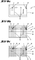
- the Figures 2a and 2b show an exemplary environment map 3 with a division of an environment into a large number of individual partial areas 10-19. Pieces of furniture and room boundaries 24 are only indicated. As shown, a grid 20 with a large number of grid cells 8, 9, which are here for example of the same size, is placed over the map of the surroundings 3, so that the partial regions 10-19 result. A plurality of sub-areas 10-19, which together form sub-area groups 4, 5, is assigned to each of the soil tillage implements 1, 2 present in the area. Each of the sub-area groups 4, 5 is only assigned to one of the tillage implements 1, 2, with the respective sub-area group 4, 5 containing the sub-area 10, 19 with the location 21, 22 of the corresponding tillage implement 1, 2.
- FIG 3 shows only an example of an area of an environment in which a route 25 of a soil cultivation device 1, 2 is drawn.
- the locomotion route 25 meanders through space, with the locomotion route 25 being assigned times which indicate the locomotion time of a tillage implement 1 in a respective Characterize section of the locomotion route 25.
- the travel route 25 contains, for example, long and short sections of the meander shape, with the tillage implement 1 requiring, for example, two minutes of travel time for the long sections and thirty seconds of travel time for the short sections.
- Figures 4 and 5 show two different embodiments of the invention by way of example, in which a large number of sub-areas 10 - 19 to be worked on are assigned to a plurality of tillage devices 1, 2 of a tillage system in such a way that the tillage devices 1, 2 complete their tillage activities essentially simultaneously.
- the figures are discussed in more detail below.
- the invention works, for example, in such a way that a soil cultivation device 1, 2 of the system, preferably a soil cultivation device 1, 2, which will later also process partial areas 10-19 of the environment, first creates a map of the environment and travels around the environment for this purpose. While the soil cultivation device 1, 2 detects the environmental features for creating the environmental map 3, its route 25 is recorded. A travel time period is assigned to the travel route 25 , which specifies the time span required by the soil tillage implement 1 , 2 to travel the travel route 25 .
- the locomotion route 25 is here, for example, in figure 3 shown travel route 25. Sections of the travel route 25 are noted there with associated partial periods of time within which the tillage implement 1, 2 has stayed in the respective section of the travel route 25.
- the locomotion route 25 and the characteristic locomotion time span of this tillage implement 1, 2 are stored in conjunction with the map 3 of the surroundings, preferably in a local memory of the tillage implement 1, 2 or a separate memory device of the system, which is accessible to all tillage implements 1, 2.
- the soil tillage implement 1 , 2 can also detect properties of the surroundings and also note them in the surroundings map 3 or store them linked to the surroundings map 3 .
- Properties of the environment are, for example, a condition of a floor surface, including a floor type, for example divided into hard floor and carpet, a degree of pollution of the environment, a type and degree of pollution.
- the soil processing device 1, 2 can detect the current locations of soil processing devices 1, 2 of the system and locations of supply facilities for the soil processing devices 1, 2.
- the supply facilities include, for example, accumulator charging stations, supply and disposal stations for water, cleaning agents, cleaning accessories and the like.
- the soil cultivation device 1, 2 preferably travels over the entire environment, ie the user's entire home, and records the environmental features. Subsequently, not only the map of the surroundings 3 itself is known, but also the travel route 25, the associated travel time (travel time period) of the connected tillage implement 1, 2, soil types and possibly other parameters detected by the tillage implement 1, 2.
- the surroundings of the soil cultivation devices 1, 2 are now divided up in such a way that the floor area to be treated is cleaned efficiently and advantageously for the user in such a way that all soil cultivation devices 1, 2 of the system finish their soil cultivation almost simultaneously and the surroundings are thus "in one fell swoop". " is completely cleaned.
- the tillage implements 1, 2 simultaneously carry out tillage activities in different sub-areas 10-19 of the environment.
- the grid 20 is first laid over the map 3 of the surroundings, so that partial regions 10 - 19 of the same size are divided up in the map 3 of the surroundings here.
- Each grid cell 8, 9 forms an independent sub-area 10-19.
- each sub-area 10-19 is allocated to one of the tillage implements 1, 2 for processing.
- the procedure is such that a device-specific processing time span of each individual soil cultivation device 1, 2 is calculated for processing the respective sub-area 10-19.
- the previously pursuant to figure 3 recorded locomotion route 25 and locomotion time span adapted to the characteristic parameters of the respective tillage implement 1, 2.
- the travel time span measured during the reconnaissance trip along the travel route 25 is “calibrated” to the capabilities of the tillage implement 1, 2, in particular its specific travel speed during the processing activity to be carried out. That soil tillage implement 1, 2 which, according to the calculations, requires the shortest implement-specific processing time is then divided up for processing the sub-area 10-19 in question. Regarding the in the Figures 2a and 2b illustrated environment map 3, this means that corresponding grid cells 8, 9 are marked as "reserved" for this tillage implement 1, 2.
- the soil tillage implement 1, 2 with the shortest characteristic tillage period is only awarded the contract for soil tillage of the respective sub-area 10 - 19 if at the same time the sub-areas 10 - 19 previously allocated ("reserved") for this soil tillage implement 1, 2 total a total tillage period of time claim that is less than the summed up total processing time spans of the other tillage implements 1, 2 of the system.
- This methodology ensures that the tillage implements 1, 2 of the system will essentially finish their tillage activities within the surrounding area at the same time.
- the sub-areas 10-19 of the map 3 of the surroundings are successively assigned to the tillage implements 1, 2 until finally all sub-areas 10-19 are assigned to one of the tillage implements 1, 2.
- Separate sections 10 - 19 that are not directly related to others Areas 10 - 19 of the same tillage implement 1, 2 are connected, for example behind obstacles, pieces of furniture, walls, etc. arise.
- the partial area 17 is accordingly assigned to the other soil tillage implement 1, for example (see FIG Figure 2b ).
- a sub-area group 4, 5 is thus created in the map 3 of the surroundings, which has a plurality of sub-regions 10-19 which the respective soil tillage implement 1, 2 is intended to process.
- the first tillage implement 1 are here in accordance Figure 2b
- the sub-areas 15 - 19 assigned, while the second tillage implement 2 for processing the sub-areas 10 - 14 is divided.
- the division of the partial areas 10-19 among the tillage implements 1, 2 is preferably carried out centrally, for example by means of a computing device which is assigned to a server of the system.
- the server can be located, for example, in a so-called "cloud", on a local computer in a household or within a tillage implement 1, 2 itself Tillage devices 1, 2 of the system transmitted or made available for retrieval, so that the tillage activities can be started. Provision can be made for the tillage implements 1, 2 to check during execution of the tillage activity whether the planned device-specific processing time can be adhered to.
- sub-areas 10 - 19 which, for example, border on the sub-areas 10 - 19 of other soil tillage implements 1, 2, the other Tillage implements 1, 2 are assigned. This ensures that during tillage, compliance with the planned tillage period is monitored in such a way that tillage implements 1, 2 essentially end tillage of sub-area groups 4-7 assigned to them at the same time.
- those grid cells 8, 9 that contain the locations 21, 22 of the tillage implements 1, 2 are marked for the respective tillage implement 1, 2, i.e. the grid cells 8, 9 with the location 21 of the first tillage implement 1 correspond to the first tillage implement 1 is assigned for processing and the Location 22 of the second tillage implement 2 corresponding to the second tillage implement 2.
- a total processing time span is added up, which includes the individual processing time spans for the sub-areas 10-19 already allocated to the soil cultivation device 1, 2.
- the first soil cultivation device 1 is already assigned to work on the sub-areas 10 and 11, which requires a total processing time of, for example, two minutes, while the second soil cultivation device 2 has so far only been scheduled to work on the sub-area 15, which processing takes, for example, a processing time of one minute .
- a next sub-area 16 assigned which is the portion 15 of the second tillage implement 2 adjacent.
- a distance of the soil tillage implements 1, 2 to the sub-area 16 is taken into account or calculated in order to determine the soil tillage implement 1, 2 that is to be assigned to work on this sub-area 16.
- the partial area 16 is assigned to the second soil cultivation device 2 , since this has the lowest total cultivation time to date and is also adjacent to the partial area 15 of the second soil cultivation device 2 .
- the allocation of the remaining sub-areas 12-14, 17-19 is continued until finally sub-area groups 4, 5 are formed, which include all sub-areas 10-19 of the environment (see Figure 4j ).
- the unassigned partial areas (blank grid cells 8, 9) cannot be driven on by any of the tillage implements 1, 2, for example because objects are covering the floor area there.
- the navigable and assigned sub-areas 10 - 19 are combined into sub-area groups 4, 5 so that the tillage implements 1, 2 finish their tillage in the assigned sub-area groups 4, 5 essentially at the same time.
- subarea groups 4 - 7 are identified in the created area map 3 within the floor plan 23 .
- the partition groups 4 - 7 are partitioned off by room boundaries 24 .
- the total area of the environment map 3 is thus broken down here into functional sub-areas, namely rooms in an apartment, for example a kitchen, a bedroom, a hallway, a living room and a bathroom.
- device-specific total processing times for the sub-area groups 4 - 7 are determined, which the respective tillage implement 1, 2 would need to process the respective sub-area group 4 - 7, with each of the sub-area groups 4 - 7 in turn being divided into individual Sections 10 - 19 (not shown) could be divided.
- the sub-area groups 4-7 are assigned to the tillage implements 1, 2 in such a way that the respective total tillage times of the tillage implements 1, 2 are approximately the same.
- four sub-area groups 4 - 7 are created here, for example.
- the exploring soil tillage implement 1, 2 has required a period of 37 minutes for the first sub-area group 4, for the second sub-area group 5 a period of 20 minutes, for the third sub-area group 6 a period of 5 minutes and for the fourth partition group 7 a period of 7 minutes.
- the sub-area groups 4 - 7 are assigned here to the soil processing devices 1, 2 in such a way that the first soil processing device 1 for Processing of the sub-area groups 4 and 6 is used, while the sub-area groups 5 and 7 are to be processed by the second tillage implement 2.
- Both soil tillage implements 1, 2 each require 42 minutes for the processing of the sub-area groups 4-7 assigned to them and are therefore finished with the soil tillage at the same time.
- the specific time span of the exploring soil tillage implement 1, 2 is initially based on the characteristic parameters of the soil tillage implement taking over the soil tillage Tillage implement 1, 2 to convert, and then finally the sub-area groups 4 - 7 to assign so that the tillage by the tillage implements 1, 2 can be completed simultaneously or substantially.
Landscapes
- Engineering & Computer Science (AREA)
- Radar, Positioning & Navigation (AREA)
- Physics & Mathematics (AREA)
- Remote Sensing (AREA)
- Automation & Control Theory (AREA)
- General Physics & Mathematics (AREA)
- Aviation & Aerospace Engineering (AREA)
- Mechanical Engineering (AREA)
- Human Computer Interaction (AREA)
- Manufacturing & Machinery (AREA)
- Optics & Photonics (AREA)
- Electromagnetism (AREA)
- Control Of Position, Course, Altitude, Or Attitude Of Moving Bodies (AREA)
- Management, Administration, Business Operations System, And Electronic Commerce (AREA)
- Processing Of Solid Wastes (AREA)
Claims (10)
- Procédé de fonctionnement d'un système comprenant au moins deux appareils de traitement du sol (1, 2) se déplaçant automatiquement, dans lequel au moins un des appareils de traitement du sol (1, 2) détecte des caractéristiques d'environnement d'un environnement et établit une carte d'environnement (3) à l'aide des caractéristiques d'environnement détectées, dans lequel la carte d'environnement (3) est divisée en zones partielles (10 - 19) et les zones partielles (10 - 19) sont attribuées aux appareils de traitement du sol (1, 2) de manière que chaque zone partielle (10 - 19) ne soit traitée que par l'un des appareils de traitement du sol (1, 2), caractérisé en ce que qu'un itinéraire de déplacement (25) de l'appareil de traitement du sol (1, 2) suivi pendant la détection des caractéristiques d'environnement ainsi qu'un laps de temps de déplacement écoulé lors du déplacement le long de l'itinéraire de déplacement (25) sont détectés et mémorisés avec la carte d'environnement (3), dans lequel plusieurs zones partielles (10 - 19) sont regroupées en groupes de zones partielles (4 - 7) et dans lequel l'attribution des zones partielles (10 - 19) aux appareils de traitement du sol (1, 2) s'effectue en tenant compte de l'itinéraire de déplacement (25) et du laps de temps de déplacement mémorisés de telle manière qu'un traitement du sol d'un premier groupe de zones partielles (4 - 7) par un premier appareil de traitement du sol (1) soit terminé sensiblement en même temps qu'un traitement du sol d'un deuxième groupe de zones partielles (4 - 7) par un deuxième appareil de traitement du sol (1), dans lequel le laps de temps de déplacement écoulé pendant la détection des caractéristiques d'environnement de l'environnement est converti en un laps de temps individuel nécessaire à un appareil de traitement du sol déterminé (1, 2) pour le traitement de la zone partielle respective (10 - 19) en comparant une vitesse de déplacement de l'appareil de traitement du sol (1, 2) détectant les caractéristiques d'environnement à une vitesse de déplacement caractéristique d'un appareil de traitement du sol (1, 2) à planifier, et dans lequel une information est attribuée à chaque zone partielle (10 - 19) de l'environnement qui indique si l'appareil de traitement du sol (1, 2) détectant les caractéristiques d'environnement a traversé la zone partielle (10-19) et combien de temps l'appareil de traitement du sol (1, 2) est alors resté dans la zone partielle (10-19).
- Procédé selon la revendication 1, caractérisé en ce que pour chaque zone partielle (10 - 19) est déterminé individuellement le laps de temps de traitement spécifique à l'appareil dont chacun des appareils de traitement du sol (1, 2) aurait besoin pour traiter cette zone partielle (10 - 19), dans lequel l'appareil de traitement du sol (1, 2) dont le laps de temps de traitement déterminé est le plus petit est planifié pour traiter cette zone partielle (10 - 19).
- Procédé selon la revendication 1 ou 2, caractérisé en ce que pour chaque zone partielle (10 - 19) est mémorisée une information sur un type de sol à traiter dans la zone partielle (10 - 19) et pour chaque appareil de traitement du sol (1, 2) est déterminé individuellement quel laps de temps de traitement spécifique au type de sol serait nécessaire à l'appareil de traitement du sol (1, 2) respectif pour traiter cette zone partielle (10 - 19).
- Procédé selon la revendication 2 ou 3, caractérisé en ce que les laps de temps de traitement nécessaires à un appareil de traitement du sol (1, 2) pour traiter plusieurs zones partielles (10-19) sont additionnés pour former un laps de temps de traitement total, dans lequel est planifié pour traiter une autre zone partielle (10-19) l'appareil de traitement du sol (1, 2) dont le laps de temps total déterminé sans tenir compte du laps de temps de traitement de l'autre zone partielle (10-19) est le plus petit pour les activités de traitement du sol planifiées jusqu'à là.
- Procédé selon l'une des revendications précédentes, caractérisé en ce qu'à une zone partielle (10 - 19) déjà planifiée pour un traitement du sol par l'un des appareils de traitement du sol (1, 2) ou à un groupe de zones partielles (4 - 7) déjà planifié pour un traitement du sol par l'un des appareils de traitement du sol (1, 2) est ajouté une telle zone partielle (10 - 19) qui est directement adjacente à la zone partielle planifiée (10 - 19) ou au groupe de zones partielles planifié (4 - 7).
- Procédé selon la revendication 5, caractérisé en ce qu'est ajouté d'abord une telle zone partielle (10 - 19) parmi plusieurs zones partielles adjacentes non encore planifiées, qui présente une distance maximale par rapport à une zone partielle (10 - 19) déjà planifiée pour le traitement par un autre appareil de traitement du sol (1, 2) ou à un groupe de zones partielles (4 - 7) déjà planifié pour le traitement par un autre appareil de traitement du sol (1, 2).
- Procédé selon l'une des revendications précédentes, caractérisé en ce qu'une zone partielle (10 - 19) qui n'est pas encore attribuée à un appareil de traitement du sol (1, 2) et qui n'est pas adjacente à une zone partielle (10 - 19) ou à un groupe de zones partielles (4 - 7) déjà planifié pour un traitement du sol par l'un des appareils de traitement du sol (1, 2) est attribuée pour traitement à un appareil de traitement du sol (1, 2) dont l'emplacement actuel (21, 22) présente une distance la plus petite par rapport à la zone partielle (10 - 19) non encore attribuée.
- Procédé selon l'une des revendications précédentes, caractérisé en ce que le regroupement des zones partielles (10 - 19) en groupes de zones partielles (4 - 7) s'effectue sur la base d'un plan (23) établi de l'environnement de manière que des délimitations d'espace (24) du plan (23) délimitent des groupes de zones partielles (4 - 7), dans lequel pour chaque groupe de zones partielles est déterminée quelle durée de travail l'appareil de traitement du sol (1, 2) respectif aurait besoin pour traiter ce groupe de zones partielles (4 - 7), et dans lequel les groupes de zones partielles (4 - 7) sont attribués aux appareils de traitement du sol (1, 2) pour un traitement du sol de telle manière que les traitements du sol des groupes de zones partielles (4 - 7) sont terminés sensiblement en même temps.
- Procédé selon l'une des revendications précédentes, caractérisé en ce qu'une activité de traitement du sol d'un appareil de traitement du sol (1, 2) dans une zone partielle déterminée (10 - 19) n'est planifiée que si l'appareil de traitement du sol (1, 2) est adapté à un traitement du sol de cette zone partielle (10 - 19).
- Système comprenant au moins deux appareils de traitement du sol (1, 2), caractérisé en ce que le système est conçu pour mettre en œuvre un procédé selon l'une des revendications précédentes.
Applications Claiming Priority (1)
| Application Number | Priority Date | Filing Date | Title |
|---|---|---|---|
| DE102020100666.7A DE102020100666A1 (de) | 2020-01-14 | 2020-01-14 | Verfahren zum Betrieb eines Systems mit mindestens zwei sich selbsttätig fortbewegenden Bodenbearbeitungsgeräten sowie System zur Durchführung eines solchen Verfahrens |
Publications (2)
| Publication Number | Publication Date |
|---|---|
| EP3851929A1 EP3851929A1 (fr) | 2021-07-21 |
| EP3851929B1 true EP3851929B1 (fr) | 2022-07-20 |
Family
ID=74105881
Family Applications (1)
| Application Number | Title | Priority Date | Filing Date |
|---|---|---|---|
| EP21150474.1A Active EP3851929B1 (fr) | 2020-01-14 | 2021-01-07 | Procédé de fonctionnement d'un système comprenant au moins deux appareils de traitement du sol mobiles automatiques ainsi que système de mise en oeuvre d'un tel procédé |
Country Status (5)
| Country | Link |
|---|---|
| US (1) | US11788860B2 (fr) |
| EP (1) | EP3851929B1 (fr) |
| CN (1) | CN113189976A (fr) |
| DE (1) | DE102020100666A1 (fr) |
| ES (1) | ES2926856T3 (fr) |
Families Citing this family (1)
| Publication number | Priority date | Publication date | Assignee | Title |
|---|---|---|---|---|
| DE102022202326A1 (de) * | 2022-03-08 | 2023-09-14 | BSH Hausgeräte GmbH | Kooperative Bodenbearbeitung |
Family Cites Families (14)
| Publication number | Priority date | Publication date | Assignee | Title |
|---|---|---|---|---|
| JP5735940B2 (ja) * | 2012-09-11 | 2015-06-17 | シャープ株式会社 | サーバ、制御システム、自走式掃除機、プログラム、および記録媒体 |
| KR102117984B1 (ko) * | 2013-11-27 | 2020-06-02 | 한국전자통신연구원 | 군집 로봇의 협력 청소 방법 및 제어 장치 |
| JP3192303U (ja) * | 2014-05-27 | 2014-08-07 | 和光産業株式会社 | 日常清掃作業時間決定装置 |
| CN104932495A (zh) * | 2015-05-13 | 2015-09-23 | 刘鹏军 | 基于无线网络协同工作的清洁机器人系统 |
| CN105892321B (zh) * | 2016-04-28 | 2018-11-23 | 京东方科技集团股份有限公司 | 一种清洁机器人的调度方法及调度装置 |
| CN106527446B (zh) * | 2016-12-02 | 2020-11-13 | 北京小米移动软件有限公司 | 扫地机器人的控制方法及装置 |
| DE102017207341A1 (de) | 2017-05-02 | 2018-11-08 | Henkel Ag & Co. Kgaa | Verfahren zur Steuerung von Reinigungsgeräten |
| DE102017113288A1 (de) * | 2017-06-16 | 2018-12-20 | Vorwerk & Co. Interholding Gmbh | System mit mindestens zwei Bodenbearbeitungseinrichtungen |
| DE102017118380A1 (de) * | 2017-08-11 | 2019-02-14 | Vorwerk & Co. Interholding Gmbh | Verfahren zum Betrieb eines sich selbsttätig fortbewegenden Reinigungsgerätes |
| DE102018111509A1 (de) * | 2018-05-14 | 2019-11-14 | Hako Gmbh | Verfahren zur Bestimmung einer Route für eine Bodenreinigungsmaschine |
| CN108563231B (zh) * | 2018-05-31 | 2021-07-23 | 北京智行者科技有限公司 | 一种清扫任务规划方法 |
| KR102096564B1 (ko) * | 2018-06-25 | 2020-04-02 | 엘지전자 주식회사 | 복수의 자율주행 청소기 |
| TWI660275B (zh) * | 2018-06-27 | 2019-05-21 | 廣達電腦股份有限公司 | 用於清潔裝置之任務區域分配方法、清潔裝置任務分配系統以及清潔裝置 |
| KR102015498B1 (ko) * | 2018-06-27 | 2019-10-23 | 엘지전자 주식회사 | 복수의 자율주행 청소기 및 그 제어방법 |
-
2020
- 2020-01-14 DE DE102020100666.7A patent/DE102020100666A1/de not_active Withdrawn
-
2021
- 2021-01-07 ES ES21150474T patent/ES2926856T3/es active Active
- 2021-01-07 EP EP21150474.1A patent/EP3851929B1/fr active Active
- 2021-01-13 US US17/147,622 patent/US11788860B2/en active Active
- 2021-01-13 CN CN202110040922.5A patent/CN113189976A/zh active Pending
Also Published As
| Publication number | Publication date |
|---|---|
| US20210215502A1 (en) | 2021-07-15 |
| DE102020100666A1 (de) | 2021-07-15 |
| US11788860B2 (en) | 2023-10-17 |
| ES2926856T3 (es) | 2022-10-31 |
| EP3851929A1 (fr) | 2021-07-21 |
| CN113189976A (zh) | 2021-07-30 |
Similar Documents
| Publication | Publication Date | Title |
|---|---|---|
| EP3616016B1 (fr) | Procédé permettant la navigation d'un robot | |
| EP3619585B1 (fr) | Procédé de commande d'appareils de nettoyage | |
| EP3367200B1 (fr) | Procédé de fonctionnement d'un robot en mouvement de manière automatique | |
| DE102008050460A1 (de) | Verfahren zur Einsatzsteuerung von landwirtschaftlichen Maschinen | |
| EP3825802A1 (fr) | Système comprenant au moins deux robots autonomes de nettoyage et procédé d'exploitation du système | |
| EP3569129B1 (fr) | Procédé de détermination d'un itinéraire pour une machine de nettoyage du sol | |
| DE102012109004A1 (de) | Roboter und Verfahren zur autonomen Inspektion oder Bearbeitung von Bodenflächen | |
| DE102014110104B4 (de) | System zur Steuerung von beweglichen Mobileinheiten | |
| DE102010000174A1 (de) | Verfahren zur Reinigung eines Raumes mittels eines selbsttätig verfahrbaren Reinigungsgerätes | |
| EP3234715A1 (fr) | Procédé de cartographie d'une surface à traiter pour véhicules robots autonomes | |
| EP3415070A1 (fr) | Système pourvu d'au moins deux dispositifs de traitement du sol | |
| DE102015006014A1 (de) | Bodenbearbeitungsgerät und Verfahren zu dessen Navigation sowie Schwarm von Bodenbearbeitungsgeräten und Verfahren zu deren gemeinsamer Navigation | |
| EP3848770B1 (fr) | Procédé de fonctionnement d'un système pourvu de deux appareils de traitement du sol autonome et système destiné à la mise en oeuvre d'un tel procédé | |
| EP3851929B1 (fr) | Procédé de fonctionnement d'un système comprenant au moins deux appareils de traitement du sol mobiles automatiques ainsi que système de mise en oeuvre d'un tel procédé | |
| EP1434671B1 (fr) | Procede, systeme et programme informatique a elements de code de programme et produit de programme informatique pour assigner une surface partielle d'une surface globale repartie en plusieurs surfaces partielles a une unite mobile parmi plusieurs unites mobiles | |
| EP4014825B1 (fr) | Procédé de fonctionnement d'un appareil de traitement du sol autonome | |
| EP4039162A1 (fr) | Système de nettoyage d'un environnement | |
| EP4075230B1 (fr) | Mise à jour de carte pour un robot électroménager | |
| EP4489627A1 (fr) | Traitement de sols en interaction | |
| DE102018132175A1 (de) | System mit zwei Bodenbearbeitungsgeräten und Verfahren dafür | |
| DE102023204593A1 (de) | Verfahren zum Bestimmen eines Bewegungspfads für ein mobiles Gerät | |
| HK40016910B (en) | Method for determining a route for a floor cleaning machine | |
| WO2023208754A1 (fr) | Procédé pour faire fonctionner un appareil mobile autopropulsé | |
| DE102024203015A1 (de) | Verfahren zum Bestimmen eines Bewegungspfads für ein mobiles Gerät |
Legal Events
| Date | Code | Title | Description |
|---|---|---|---|
| PUAI | Public reference made under article 153(3) epc to a published international application that has entered the european phase |
Free format text: ORIGINAL CODE: 0009012 |
|
| STAA | Information on the status of an ep patent application or granted ep patent |
Free format text: STATUS: THE APPLICATION HAS BEEN PUBLISHED |
|
| AK | Designated contracting states |
Kind code of ref document: A1 Designated state(s): AL AT BE BG CH CY CZ DE DK EE ES FI FR GB GR HR HU IE IS IT LI LT LU LV MC MK MT NL NO PL PT RO RS SE SI SK SM TR |
|
| STAA | Information on the status of an ep patent application or granted ep patent |
Free format text: STATUS: REQUEST FOR EXAMINATION WAS MADE |
|
| 17P | Request for examination filed |
Effective date: 20211104 |
|
| RBV | Designated contracting states (corrected) |
Designated state(s): AL AT BE BG CH CY CZ DE DK EE ES FI FR GB GR HR HU IE IS IT LI LT LU LV MC MK MT NL NO PL PT RO RS SE SI SK SM TR |
|
| GRAP | Despatch of communication of intention to grant a patent |
Free format text: ORIGINAL CODE: EPIDOSNIGR1 |
|
| STAA | Information on the status of an ep patent application or granted ep patent |
Free format text: STATUS: GRANT OF PATENT IS INTENDED |
|
| RIC1 | Information provided on ipc code assigned before grant |
Ipc: G05D 1/02 20200101AFI20220217BHEP |
|
| INTG | Intention to grant announced |
Effective date: 20220303 |
|
| GRAS | Grant fee paid |
Free format text: ORIGINAL CODE: EPIDOSNIGR3 |
|
| GRAA | (expected) grant |
Free format text: ORIGINAL CODE: 0009210 |
|
| STAA | Information on the status of an ep patent application or granted ep patent |
Free format text: STATUS: THE PATENT HAS BEEN GRANTED |
|
| AK | Designated contracting states |
Kind code of ref document: B1 Designated state(s): AL AT BE BG CH CY CZ DE DK EE ES FI FR GB GR HR HU IE IS IT LI LT LU LV MC MK MT NL NO PL PT RO RS SE SI SK SM TR |
|
| REG | Reference to a national code |
Ref country code: CH Ref legal event code: EP |
|
| REG | Reference to a national code |
Ref country code: DE Ref legal event code: R096 Ref document number: 502021000074 Country of ref document: DE |
|
| REG | Reference to a national code |
Ref country code: AT Ref legal event code: REF Ref document number: 1505938 Country of ref document: AT Kind code of ref document: T Effective date: 20220815 |
|
| REG | Reference to a national code |
Ref country code: IE Ref legal event code: FG4D Free format text: LANGUAGE OF EP DOCUMENT: GERMAN |
|
| REG | Reference to a national code |
Ref country code: ES Ref legal event code: FG2A Ref document number: 2926856 Country of ref document: ES Kind code of ref document: T3 Effective date: 20221031 |
|
| REG | Reference to a national code |
Ref country code: LT Ref legal event code: MG9D |
|
| REG | Reference to a national code |
Ref country code: NL Ref legal event code: MP Effective date: 20220720 |
|
| PG25 | Lapsed in a contracting state [announced via postgrant information from national office to epo] |
Ref country code: SE Free format text: LAPSE BECAUSE OF FAILURE TO SUBMIT A TRANSLATION OF THE DESCRIPTION OR TO PAY THE FEE WITHIN THE PRESCRIBED TIME-LIMIT Effective date: 20220720 Ref country code: RS Free format text: LAPSE BECAUSE OF FAILURE TO SUBMIT A TRANSLATION OF THE DESCRIPTION OR TO PAY THE FEE WITHIN THE PRESCRIBED TIME-LIMIT Effective date: 20220720 Ref country code: PT Free format text: LAPSE BECAUSE OF FAILURE TO SUBMIT A TRANSLATION OF THE DESCRIPTION OR TO PAY THE FEE WITHIN THE PRESCRIBED TIME-LIMIT Effective date: 20221121 Ref country code: NO Free format text: LAPSE BECAUSE OF FAILURE TO SUBMIT A TRANSLATION OF THE DESCRIPTION OR TO PAY THE FEE WITHIN THE PRESCRIBED TIME-LIMIT Effective date: 20221020 Ref country code: NL Free format text: LAPSE BECAUSE OF FAILURE TO SUBMIT A TRANSLATION OF THE DESCRIPTION OR TO PAY THE FEE WITHIN THE PRESCRIBED TIME-LIMIT Effective date: 20220720 Ref country code: LV Free format text: LAPSE BECAUSE OF FAILURE TO SUBMIT A TRANSLATION OF THE DESCRIPTION OR TO PAY THE FEE WITHIN THE PRESCRIBED TIME-LIMIT Effective date: 20220720 Ref country code: LT Free format text: LAPSE BECAUSE OF FAILURE TO SUBMIT A TRANSLATION OF THE DESCRIPTION OR TO PAY THE FEE WITHIN THE PRESCRIBED TIME-LIMIT Effective date: 20220720 Ref country code: FI Free format text: LAPSE BECAUSE OF FAILURE TO SUBMIT A TRANSLATION OF THE DESCRIPTION OR TO PAY THE FEE WITHIN THE PRESCRIBED TIME-LIMIT Effective date: 20220720 |
|
| PG25 | Lapsed in a contracting state [announced via postgrant information from national office to epo] |
Ref country code: PL Free format text: LAPSE BECAUSE OF FAILURE TO SUBMIT A TRANSLATION OF THE DESCRIPTION OR TO PAY THE FEE WITHIN THE PRESCRIBED TIME-LIMIT Effective date: 20220720 Ref country code: IS Free format text: LAPSE BECAUSE OF FAILURE TO SUBMIT A TRANSLATION OF THE DESCRIPTION OR TO PAY THE FEE WITHIN THE PRESCRIBED TIME-LIMIT Effective date: 20221120 Ref country code: HR Free format text: LAPSE BECAUSE OF FAILURE TO SUBMIT A TRANSLATION OF THE DESCRIPTION OR TO PAY THE FEE WITHIN THE PRESCRIBED TIME-LIMIT Effective date: 20220720 Ref country code: GR Free format text: LAPSE BECAUSE OF FAILURE TO SUBMIT A TRANSLATION OF THE DESCRIPTION OR TO PAY THE FEE WITHIN THE PRESCRIBED TIME-LIMIT Effective date: 20221021 |
|
| REG | Reference to a national code |
Ref country code: DE Ref legal event code: R097 Ref document number: 502021000074 Country of ref document: DE |
|
| PG25 | Lapsed in a contracting state [announced via postgrant information from national office to epo] |
Ref country code: SM Free format text: LAPSE BECAUSE OF FAILURE TO SUBMIT A TRANSLATION OF THE DESCRIPTION OR TO PAY THE FEE WITHIN THE PRESCRIBED TIME-LIMIT Effective date: 20220720 Ref country code: RO Free format text: LAPSE BECAUSE OF FAILURE TO SUBMIT A TRANSLATION OF THE DESCRIPTION OR TO PAY THE FEE WITHIN THE PRESCRIBED TIME-LIMIT Effective date: 20220720 Ref country code: DK Free format text: LAPSE BECAUSE OF FAILURE TO SUBMIT A TRANSLATION OF THE DESCRIPTION OR TO PAY THE FEE WITHIN THE PRESCRIBED TIME-LIMIT Effective date: 20220720 Ref country code: CZ Free format text: LAPSE BECAUSE OF FAILURE TO SUBMIT A TRANSLATION OF THE DESCRIPTION OR TO PAY THE FEE WITHIN THE PRESCRIBED TIME-LIMIT Effective date: 20220720 |
|
| PLBE | No opposition filed within time limit |
Free format text: ORIGINAL CODE: 0009261 |
|
| STAA | Information on the status of an ep patent application or granted ep patent |
Free format text: STATUS: NO OPPOSITION FILED WITHIN TIME LIMIT |
|
| PG25 | Lapsed in a contracting state [announced via postgrant information from national office to epo] |
Ref country code: SK Free format text: LAPSE BECAUSE OF FAILURE TO SUBMIT A TRANSLATION OF THE DESCRIPTION OR TO PAY THE FEE WITHIN THE PRESCRIBED TIME-LIMIT Effective date: 20220720 Ref country code: EE Free format text: LAPSE BECAUSE OF FAILURE TO SUBMIT A TRANSLATION OF THE DESCRIPTION OR TO PAY THE FEE WITHIN THE PRESCRIBED TIME-LIMIT Effective date: 20220720 |
|
| P01 | Opt-out of the competence of the unified patent court (upc) registered |
Effective date: 20230517 |
|
| 26N | No opposition filed |
Effective date: 20230421 |
|
| PG25 | Lapsed in a contracting state [announced via postgrant information from national office to epo] |
Ref country code: AL Free format text: LAPSE BECAUSE OF FAILURE TO SUBMIT A TRANSLATION OF THE DESCRIPTION OR TO PAY THE FEE WITHIN THE PRESCRIBED TIME-LIMIT Effective date: 20220720 |
|
| PG25 | Lapsed in a contracting state [announced via postgrant information from national office to epo] |
Ref country code: SI Free format text: LAPSE BECAUSE OF FAILURE TO SUBMIT A TRANSLATION OF THE DESCRIPTION OR TO PAY THE FEE WITHIN THE PRESCRIBED TIME-LIMIT Effective date: 20220720 |
|
| PG25 | Lapsed in a contracting state [announced via postgrant information from national office to epo] |
Ref country code: LU Free format text: LAPSE BECAUSE OF NON-PAYMENT OF DUE FEES Effective date: 20230107 |
|
| REG | Reference to a national code |
Ref country code: BE Ref legal event code: MM Effective date: 20230131 |
|
| REG | Reference to a national code |
Ref country code: DE Ref legal event code: R079 Ref document number: 502021000074 Country of ref document: DE Free format text: PREVIOUS MAIN CLASS: G05D0001020000 Ipc: G05D0001430000 |
|
| PG25 | Lapsed in a contracting state [announced via postgrant information from national office to epo] |
Ref country code: BE Free format text: LAPSE BECAUSE OF NON-PAYMENT OF DUE FEES Effective date: 20230131 |
|
| PG25 | Lapsed in a contracting state [announced via postgrant information from national office to epo] |
Ref country code: IE Free format text: LAPSE BECAUSE OF NON-PAYMENT OF DUE FEES Effective date: 20230107 |
|
| PG25 | Lapsed in a contracting state [announced via postgrant information from national office to epo] |
Ref country code: MC Free format text: LAPSE BECAUSE OF FAILURE TO SUBMIT A TRANSLATION OF THE DESCRIPTION OR TO PAY THE FEE WITHIN THE PRESCRIBED TIME-LIMIT Effective date: 20220720 |
|
| PG25 | Lapsed in a contracting state [announced via postgrant information from national office to epo] |
Ref country code: MC Free format text: LAPSE BECAUSE OF FAILURE TO SUBMIT A TRANSLATION OF THE DESCRIPTION OR TO PAY THE FEE WITHIN THE PRESCRIBED TIME-LIMIT Effective date: 20220720 |
|
| REG | Reference to a national code |
Ref country code: CH Ref legal event code: PL |
|
| PG25 | Lapsed in a contracting state [announced via postgrant information from national office to epo] |
Ref country code: CH Free format text: LAPSE BECAUSE OF NON-PAYMENT OF DUE FEES Effective date: 20240131 |
|
| PG25 | Lapsed in a contracting state [announced via postgrant information from national office to epo] |
Ref country code: CH Free format text: LAPSE BECAUSE OF NON-PAYMENT OF DUE FEES Effective date: 20240131 |
|
| PG25 | Lapsed in a contracting state [announced via postgrant information from national office to epo] |
Ref country code: BG Free format text: LAPSE BECAUSE OF FAILURE TO SUBMIT A TRANSLATION OF THE DESCRIPTION OR TO PAY THE FEE WITHIN THE PRESCRIBED TIME-LIMIT Effective date: 20220720 |
|
| PG25 | Lapsed in a contracting state [announced via postgrant information from national office to epo] |
Ref country code: BG Free format text: LAPSE BECAUSE OF FAILURE TO SUBMIT A TRANSLATION OF THE DESCRIPTION OR TO PAY THE FEE WITHIN THE PRESCRIBED TIME-LIMIT Effective date: 20220720 |
|
| PGFP | Annual fee paid to national office [announced via postgrant information from national office to epo] |
Ref country code: AT Payment date: 20250417 Year of fee payment: 5 |
|
| PG25 | Lapsed in a contracting state [announced via postgrant information from national office to epo] |
Ref country code: CY Free format text: LAPSE BECAUSE OF FAILURE TO SUBMIT A TRANSLATION OF THE DESCRIPTION OR TO PAY THE FEE WITHIN THE PRESCRIBED TIME-LIMIT; INVALID AB INITIO Effective date: 20210107 |
|
| PG25 | Lapsed in a contracting state [announced via postgrant information from national office to epo] |
Ref country code: HU Free format text: LAPSE BECAUSE OF FAILURE TO SUBMIT A TRANSLATION OF THE DESCRIPTION OR TO PAY THE FEE WITHIN THE PRESCRIBED TIME-LIMIT; INVALID AB INITIO Effective date: 20210107 |
|
| GBPC | Gb: european patent ceased through non-payment of renewal fee |
Effective date: 20250107 |
|
| PG25 | Lapsed in a contracting state [announced via postgrant information from national office to epo] |
Ref country code: GB Free format text: LAPSE BECAUSE OF NON-PAYMENT OF DUE FEES Effective date: 20250107 |
|
| PG25 | Lapsed in a contracting state [announced via postgrant information from national office to epo] |
Ref country code: TR Free format text: LAPSE BECAUSE OF FAILURE TO SUBMIT A TRANSLATION OF THE DESCRIPTION OR TO PAY THE FEE WITHIN THE PRESCRIBED TIME-LIMIT Effective date: 20220720 |
|
| PGFP | Annual fee paid to national office [announced via postgrant information from national office to epo] |
Ref country code: ES Payment date: 20260217 Year of fee payment: 6 |
|
| PGFP | Annual fee paid to national office [announced via postgrant information from national office to epo] |
Ref country code: DE Payment date: 20260120 Year of fee payment: 6 |
|
| PGFP | Annual fee paid to national office [announced via postgrant information from national office to epo] |
Ref country code: IT Payment date: 20260130 Year of fee payment: 6 |
|
| PGFP | Annual fee paid to national office [announced via postgrant information from national office to epo] |
Ref country code: FR Payment date: 20260121 Year of fee payment: 6 |