EP3852202A1 - Verbinder - Google Patents
Verbinder Download PDFInfo
- Publication number
- EP3852202A1 EP3852202A1 EP21151768.5A EP21151768A EP3852202A1 EP 3852202 A1 EP3852202 A1 EP 3852202A1 EP 21151768 A EP21151768 A EP 21151768A EP 3852202 A1 EP3852202 A1 EP 3852202A1
- Authority
- EP
- European Patent Office
- Prior art keywords
- housing
- connector
- buffer member
- bent
- metal terminals
- Prior art date
- Legal status (The legal status is an assumption and is not a legal conclusion. Google has not performed a legal analysis and makes no representation as to the accuracy of the status listed.)
- Withdrawn
Links
Images


Classifications
-
- H—ELECTRICITY
- H01—ELECTRIC ELEMENTS
- H01R—ELECTRICALLY-CONDUCTIVE CONNECTIONS; STRUCTURAL ASSOCIATIONS OF A PLURALITY OF MUTUALLY-INSULATED ELECTRICAL CONNECTING ELEMENTS; COUPLING DEVICES; CURRENT COLLECTORS
- H01R13/00—Details of coupling devices of the kinds covered by groups H01R12/70 or H01R24/00 - H01R33/00
- H01R13/40—Securing contact members in or to a base or case; Insulating of contact members
- H01R13/405—Securing in non-demountable manner, e.g. moulding, riveting
-
- H—ELECTRICITY
- H01—ELECTRIC ELEMENTS
- H01R—ELECTRICALLY-CONDUCTIVE CONNECTIONS; STRUCTURAL ASSOCIATIONS OF A PLURALITY OF MUTUALLY-INSULATED ELECTRICAL CONNECTING ELEMENTS; COUPLING DEVICES; CURRENT COLLECTORS
- H01R13/00—Details of coupling devices of the kinds covered by groups H01R12/70 or H01R24/00 - H01R33/00
- H01R13/46—Bases; Cases
- H01R13/52—Dustproof, splashproof, drip-proof, waterproof, or flameproof cases
- H01R13/521—Sealing between contact members and housing, e.g. sealing insert
-
- H—ELECTRICITY
- H01—ELECTRIC ELEMENTS
- H01R—ELECTRICALLY-CONDUCTIVE CONNECTIONS; STRUCTURAL ASSOCIATIONS OF A PLURALITY OF MUTUALLY-INSULATED ELECTRICAL CONNECTING ELEMENTS; COUPLING DEVICES; CURRENT COLLECTORS
- H01R13/00—Details of coupling devices of the kinds covered by groups H01R12/70 or H01R24/00 - H01R33/00
- H01R13/46—Bases; Cases
- H01R13/52—Dustproof, splashproof, drip-proof, waterproof, or flameproof cases
-
- H—ELECTRICITY
- H01—ELECTRIC ELEMENTS
- H01R—ELECTRICALLY-CONDUCTIVE CONNECTIONS; STRUCTURAL ASSOCIATIONS OF A PLURALITY OF MUTUALLY-INSULATED ELECTRICAL CONNECTING ELEMENTS; COUPLING DEVICES; CURRENT COLLECTORS
- H01R13/00—Details of coupling devices of the kinds covered by groups H01R12/70 or H01R24/00 - H01R33/00
- H01R13/02—Contact members
- H01R13/04—Pins or blades for co-operation with sockets
-
- H—ELECTRICITY
- H01—ELECTRIC ELEMENTS
- H01R—ELECTRICALLY-CONDUCTIVE CONNECTIONS; STRUCTURAL ASSOCIATIONS OF A PLURALITY OF MUTUALLY-INSULATED ELECTRICAL CONNECTING ELEMENTS; COUPLING DEVICES; CURRENT COLLECTORS
- H01R13/00—Details of coupling devices of the kinds covered by groups H01R12/70 or H01R24/00 - H01R33/00
- H01R13/46—Bases; Cases
- H01R13/502—Bases; Cases composed of different pieces
- H01R13/504—Bases; Cases composed of different pieces different pieces being moulded, cemented, welded, e.g. ultrasonic welding, or swaged together
-
- H—ELECTRICITY
- H01—ELECTRIC ELEMENTS
- H01R—ELECTRICALLY-CONDUCTIVE CONNECTIONS; STRUCTURAL ASSOCIATIONS OF A PLURALITY OF MUTUALLY-INSULATED ELECTRICAL CONNECTING ELEMENTS; COUPLING DEVICES; CURRENT COLLECTORS
- H01R13/00—Details of coupling devices of the kinds covered by groups H01R12/70 or H01R24/00 - H01R33/00
- H01R13/46—Bases; Cases
- H01R13/52—Dustproof, splashproof, drip-proof, waterproof, or flameproof cases
- H01R13/5202—Sealing means between parts of housing or between housing part and a wall, e.g. sealing rings
-
- H—ELECTRICITY
- H01—ELECTRIC ELEMENTS
- H01R—ELECTRICALLY-CONDUCTIVE CONNECTIONS; STRUCTURAL ASSOCIATIONS OF A PLURALITY OF MUTUALLY-INSULATED ELECTRICAL CONNECTING ELEMENTS; COUPLING DEVICES; CURRENT COLLECTORS
- H01R13/00—Details of coupling devices of the kinds covered by groups H01R12/70 or H01R24/00 - H01R33/00
- H01R13/46—Bases; Cases
- H01R13/533—Bases, cases made for use in extreme conditions, e.g. high temperature, radiation, vibration, corrosive environment, pressure
-
- H—ELECTRICITY
- H01—ELECTRIC ELEMENTS
- H01R—ELECTRICALLY-CONDUCTIVE CONNECTIONS; STRUCTURAL ASSOCIATIONS OF A PLURALITY OF MUTUALLY-INSULATED ELECTRICAL CONNECTING ELEMENTS; COUPLING DEVICES; CURRENT COLLECTORS
- H01R2201/00—Connectors or connections adapted for particular applications
- H01R2201/26—Connectors or connections adapted for particular applications for vehicles
-
- H—ELECTRICITY
- H01—ELECTRIC ELEMENTS
- H01R—ELECTRICALLY-CONDUCTIVE CONNECTIONS; STRUCTURAL ASSOCIATIONS OF A PLURALITY OF MUTUALLY-INSULATED ELECTRICAL CONNECTING ELEMENTS; COUPLING DEVICES; CURRENT COLLECTORS
- H01R24/00—Two-part coupling devices, or either of their cooperating parts, characterised by their overall structure
- H01R24/60—Contacts spaced along planar side wall transverse to longitudinal axis of engagement
-
- H—ELECTRICITY
- H01—ELECTRIC ELEMENTS
- H01R—ELECTRICALLY-CONDUCTIVE CONNECTIONS; STRUCTURAL ASSOCIATIONS OF A PLURALITY OF MUTUALLY-INSULATED ELECTRICAL CONNECTING ELEMENTS; COUPLING DEVICES; CURRENT COLLECTORS
- H01R43/00—Apparatus or processes specially adapted for manufacturing, assembling, maintaining, or repairing of line connectors or current collectors or for joining electric conductors
- H01R43/18—Apparatus or processes specially adapted for manufacturing, assembling, maintaining, or repairing of line connectors or current collectors or for joining electric conductors for manufacturing bases or cases for contact members
Definitions
- the present invention relates to a connector in which a metal conductor is held in a housing formed of a resin material.
- the related art proposed a connector in which a terminal fitting is insert-molded in a housing formed of a resin material.
- a sealing material in a liquid form is injected and cured so as to close a gap between the terminal fitting and the housing.
- the cured sealing material acts as a water stopping member that prevents water from entering from one fitting space to the other fitting space.
- JP 2013-157256 A As for details of the above connector, refer to JP 2013-157256 A .
- an internal stress may occur inside each of the housing and the terminal fitting around a boundary surface between the housing and the terminal fitting due to a difference in thermal deformation degrees of the housing and the terminal fitting.
- a large internal stress tends to occur (so-called stress concentration occurs) at a portion where the boundary surface between the housing and the terminal fitting is bent with a small radius of curvature.
- the boundary surface between the housing and the terminal fitting also has a bent portion.
- deformation, cracking, or the like may occur in the housing starting from the bent portion. Since such deformation or cracking may cause a reduction in strength of the housing, it is preferable that there is no such deformation or cracking.
- a water stopping property cannot be exhibited as designed.
- it is desirable that the strength of the housing is maintained as much as possible even when the connector is exposed to a temperature change from the viewpoint of properly exhibiting an original function.
- aspects of non-limiting embodiments of the present disclosure relate to providing a connector having excellent resistance to a temperature change.
- aspects of certain non-limiting embodiments of the present disclosure address the features discussed above and/or other features not described above. However, aspects of the non-limiting embodiments are not required to address the above features, and aspects of the non-limiting embodiments of the present disclosure may not address features described above.
- a connector comprising:
- the connector 1 shown in Fig. 1 is attached to an outer wall 40 of a case of a drive system component for a vehicle as shown in Fig. 3 .
- the connector 1 is used in a state in which a front connector portion 12 is exposed to oil (such as hydraulic oil) in the case and a rear connector portion 13 is exposed to air or water.
- oil such as hydraulic oil
- an outer surface 41 of the outer wall 40 is exposed to air or water outside the case, and an inner surface 42 of the outer wall 40 is exposed to oil stored in the case.
- the connector 1 functions as a relay connector that electrically connects a counterpart front connector (not shown) fitted to the front connector portion 12 and a counterpart rear connector (not shown) fitted to the rear connector portion 13.
- a "front-rear direction”, a “width direction”, an “upper-lower direction”, “front”, and “rear” as shown in Fig.1 will be defined for the convenience of description.
- the "front-rear direction”, the “width direction”, and the “upper-lower direction” are orthogonal to one another.
- the front-rear direction coincides with a fitting direction of the front connector portion 12 and the counterpart front connector and a fitting direction of the rear connector portion 13 and the counterpart rear connector.
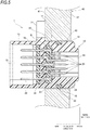
- the connector 1 includes a housing 10, a plurality of metal terminals 20 held in the housing 10, and a buffer member 30 embedded in the housing 10 in a state of collectively covering intermediate portions 23 (see Fig. 5 ) of the plurality of metal terminals 20.
- the housing 10 is a resin molded product. As shown in Figs. 1 to 3 and Fig. 5 , the housing 10 integrally includes a body portion 11, the front connector portion 12 located at a front side of the body portion 11, and the rear connector portion 13 located at a rear side of the body portion 11.
- the body portion 11 has a cylindrical shape whose axis extends in the front-rear direction.
- the intermediate portions 23 (to be described later) of the plurality of metal terminals 20 and the buffer member 30 that collectively covers a plurality of intermediate portions 23 are embedded in the body portion 11 by insert-molding.
- the front connector portion 12 has a shape having an outer peripheral cylindrical surface extending coaxially from an outer peripheral cylindrical surface of the body portion 11 and extending continuously to the front side.
- a fitting recessed portion 14 recessed rearward is formed on a front end surface of the front connector portion 12.
- a bottom surface of the fitting recessed portion 14 is formed by a part of a front end surface of the body portion 11. The counterpart front connector is fitted to the fitting recessed portion 14.
- the rear connector portion 13 has a rectangular tubular shape protruding rearward from a rear end surface of the body portion 11. As shown in Figs. 2 and 5 , a fitting recessed portion 15 recessed forward is formed inside the rear connector portion 13. A bottom surface of the fitting recessed portion 15 is formed by a part of the rear end surface of the body portion 11. The counterpart rear connector is fitted to the fitting recessed portion 15.
- annular recessed portion 16 is formed on an outer peripheral surface of the front connector portion 12 (see Fig. 5 ).
- An O ring 50 is fitted in the annular recessed portion 16.
- a flange portion 17 extending radially outward from an outer peripheral surface of a rear end portion of the body portion 11 is integrally formed on the body portion 11.
- a through hole 18 that is used for collar attachment and passes through the flange portion 17 in the front-rear direction is formed at a tip end portion of the flange portion 17.
- a cylindrical collar 60 formed of metal is attached to the through hole 18.
- the housing 10 is attached to the outer wall 40 of the case by fastening and fixing the flange portion 17 to the outer wall 40 using a bolt (not shown) inserted into the collar 60 in a state in which the front connector portion 12 is inserted into an attachment hole 43 from an outer surface 41 side.
- the attachment hole 43 is formed on the outer wall 40 of the case and has a cylindrical inner peripheral surface.
- the metal terminals 20 will be described.
- the plurality of metal terminals 20 shown in Figs. 4 to 6 are manufactured by cutting so-called chain terminals respectively at predetermined positions of a strip-shaped carrier (not shown) corresponding to the metal terminals 20.
- the chain terminals are formed by coupling portions corresponding to the plurality of metal terminals 20 in a state of being aligned in a row by the carrier. Therefore, a carrier mark portion 24 remains at each of the metal terminals 20 (see Figs. 5 and 6 ).
- each metal terminal 20 includes a front contact portion 21 located at a front side and extending linearly in the front-rear direction, a rear contact portion 22 located at a rear side and extending linearly in the front-rear direction, and the intermediate portion 23 that couples the front contact portion 21 and the rear contact portion 22.
- a width of the intermediate portion 23 is larger than a width of the front contact portion 21 and a width of the rear contact portion 22.
- a plurality of (five) metal terminals 20 are aligned in a row in the width direction such that the metal terminals 20 are held in the housing 10 (the body portion 11).
- the front contact portions 21 of the plurality (five) metal terminals 20 protrude forward from the bottom surface of the fitting recessed portion 14 in the fitting recessed portion 14 of the front connector portion 12. Therefore, when the counterpart front connector is fitted to the fitting recessed portion 14, a plurality of front contact portions 21 (male terminals) and a plurality of terminals (female terminals (not shown)) accommodated in the counterpart front connector are electrically connected.
- the rear contact portions 22 of the plurality of (five) metal terminals 20 protrude rearward from the bottom surface of the fitting recessed portion 15 in the fitting recessed portion 15 of the rear connector portion 13. Therefore, when the counterpart rear connector is fitted into the fitting recessed portion 15, a plurality of rear contact portions 22 (male terminals) and a plurality of terminals (female terminals (not shown)) accommodated in the counterpart rear connector are electrically connected.
- a pitch of the plurality of rear contact portions 22 (an interval between adjacent rear contact portions 22 in the width direction) aligned in a row in the width direction is larger than a pitch of the plurality of front contact portions 21 (an interval between adjacent front contact portions 21 in the width direction) aligned in a row in the width direction. This is to ensure a space for waterproof plugs for water stopping that are separately and respectively provided at a plurality of terminals accommodated in the counterpart rear connector fitted to the fitting recessed portion 15.
- each of the intermediate portions 23 of four metal terminals 20 located at two sides in the width direction of the metal terminal 20 located at the center of the width direction has a crank shape having two bent portions 25 bent in opposite directions.
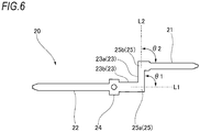
- Fig. 6 shows a schematic structure of the metal terminal 20 arranged at a lowermost end in Fig. 5 among the plurality of metal terminals 20 shown in Fig. 5 .
- a bent portion 25a of the metal terminal 20 at a lower side of Fig. 6 is interposed between a portion 23a and the other portion 23b of the intermediate portion 23.
- an angle ⁇ 1 is formed between an extension line L1 obtained by virtually extending a portion of one side that sandwiches the bent portion 25a (that is, the other portion 23b of the intermediate portion 23) and a portion of the other side that sandwiches the bent portion 25a (that is, the portion 23a of the intermediate portion 23).
- the angle ⁇ 1 is defined as a bending angle ⁇ 1 (0 degree ⁇ ⁇ 1 ⁇ 180 degrees) of the bent portion 25a.
- an angle ⁇ 2 is formed in the bent portion 25b at an upper side of Fig. 6 between an extension line L2 obtained by virtually extending a portion of one side that sandwiches the bent portion 25b (that is, the portion 23a of the intermediate portion 23) and a portion of the other side that sandwiches the bent portion 25b (that is, the front contact portion 21).
- the angle ⁇ 2 is defined as a bending angle ⁇ 2 (0 degree ⁇ ⁇ 2 ⁇ 180 degrees) of the bent portion 25b.
- the same definition can be applied to an object (for example, a boundary surface B to be described later) other than the metal terminal 20.
- the portion 23a and the other portion 23b of the intermediate portion 23 and the front contact portion 2 all have a linear shape.
- the bending angles ⁇ 1 and ⁇ 2 may be determined by approximating the shape of the portions (23a and 23b) to a linear shape, or the bending angles ⁇ 1 and ⁇ 2 may be determined using tangents of the portions (23a and 23b).
- the same definition can be applied to an object (for example, the boundary surface B to be described later) other than the metal terminal 20.
- both of the bending angles ⁇ 1 and ⁇ 2 of the bent portions 25a and 25b of the metal terminal 20 shown in Fig. 6 are 90 degrees. Except for the linear metal terminal 20 located at the center in the width direction in Fig. 5 , bending angles of the bent portions 25 of the other metal terminals 20 in Fig. 5 are all 90 degrees.
- An amount of shift between the front contact portion 21 and the rear contact portion 22 for a pair of metal terminals 20 located at two end portions in the width direction is larger than an amount of shift between the front contact portion 21 and the rear contact portion 22 for a pair of metal terminals 20 located adjacent to the metal terminal 20 located at the center in the width direction.
- the intermediate portions 23 of the plurality of metal terminals 20 are embedded in the body portion 11 of the housing 10 by insert-molding in a state in which the intermediate portions 23 of the plurality of metal terminals 20 are collectively covered by the buffer member 30.
- the buffer member 30 is formed of a resin material or a rubber material having higher flexibility than a resin material forming the housing 10.
- the buffer member 30 is molded to collectively cover the intermediate portions 23 of the plurality of metal terminals 20 using a mold (not shown) for the primary molding in a state in which the plurality of the metal terminals 20 are positioned relative to one another in a manner of being aligned in the width direction as shown in Fig. 4 .
- the intermediate portions 23 of the plurality of metal terminals 20 and the buffer member 30 are embedded into the body portion 11 using a mold (not shown) for the secondary molding. In this manner, the housing 10 is molded.
- the housing 10 is obtained in which the intermediate portions 23 of the plurality of metal terminals 20 and the buffer member 30 collectively covering the plurality of intermediate portions 23 are embedded and held in the body portion 11.
- the buffer member 30 covers the plurality of intermediate portions 23 in a manner of covering at least all of the plurality of bent portions 25 (eight portions in this example) of the plurality of intermediate portions 23. Therefore, in the housing 10, all of the plurality of bent portions 25 of the plurality of intermediate portions 23 are not directly in contact with the body portion 11, and the buffer member 30 is present between the plurality of bent portions 25 and the body portion 11.
- a minute gap is inevitably formed between each of the metal terminals 20 embedded in the body portion 11 and the body portion 11 (around side faces of the metal terminals 20) after the housing 10 is molded.
- a potting material 70 is poured toward the bottom surface of the fitting recessed portion 15 of the rear connector portion 13 when the housing 10 is maintained in an orientation in which the rear connector portion 13 faces vertically upward and the front connector portion 12 faces vertically downward. Accordingly, the potting material 70 enters the gap between each of the metal terminals 20 and the body portion 11 due to the force of gravity acting on the potting material 70, thereby sealing the gap.
- the entire outer surface of the buffer member 30 has a smooth shape formed by a flat surface or a smooth curved surface.
- the entire buffer member 30 is embedded in the body portion 11 of the housing 10. Therefore, the entire outer surface of the buffer member 30 in the body portion 11 forms the boundary surface B (see Fig. 5 ) between the buffer member 30 and the body portion 11.
- the boundary surface B has a smooth boundary shape that does not have a portion bent at a bending angle equal to or larger than the bending angle (90 degrees in this example) of the bent portion 25.
- the bending angle of the boundary surface B can be determined according to the same definition described above.
- the bent portions 25 of the metal terminals 20 formed of a metal material are covered by the buffer member 30 formed of a material having higher flexibility than a resin material forming the housing 10.
- the buffer member 30 When the buffer member 30 is embedded in the housing 10, the metal terminals 20 are held in the housing 10. That is, the bent portions 25 of the metal terminals 20 are not directly in contact with the housing 10, and the buffer member 30 is present between the bent portions 25 of the metal terminals 20 and the housing 10.
- the buffer member 30 having excellent flexibility absorbs a difference in deformation degrees of the resin material forming the housing 10 and the metal material forming the metal terminals 20, so that an internal stress occurring around the boundary surface between the metal terminals 20 and the housing 10 is reduced. Accordingly, deformation or cracking of the housing 10 is prevented.
- the boundary surface B between the housing 10 and the buffer member 30 has a smooth boundary shape that does not have a portion bent at an angle equal to or larger than the bending angle (90 degrees) of the bent portions 25 of the metal terminals 20 in any cross section of the buffer member 30. Therefore, a large internal stress can be prevented from occurring in the housing 10 around the boundary surface between the buffer member 30 and the housing 10. Therefore, the connector 1 according to the present embodiment can further improve the resistance to a temperature change.
- the buffer member 30 is not exposed to the outside of the housing 10 (in particular, a front connector portion 12 side exposed to oil). Therefore, it is not necessary to consider durability with respect to oil of a material forming the buffer member 30. Therefore, the degree of freedom of selecting the material forming the buffer member 30 is increased while focusing on excellent flexibility.
- the plurality of bent portions 25 of the plurality of metal terminals 20 are collectively covered by the buffer member 30. Therefore, as the primary molding, the buffer member 30 is molded in a state in which the plurality of metal terminals 20 are positioned relative to one another, as the secondary molding, the plurality of the metal terminals 20 and the buffer member 30 are collectively insert-molded in the housing 10, such that the connector 1 can be manufactured.
- productivity of the connector including the plurality of metal terminals 20 can be improved.
- the boundary surface B between the housing 10 and the buffer member 30 has a shape (that is, the smooth boundary shape) that does not have a portion bent at a bending angle equal to or larger than the bending angle (90 degrees) of the bent portions 25 of the metal terminals 20 in any cross section of the buffer member 30.
- the boundary surface B between the housing 10 and the buffer member 30 may have a portion bent at a bending angle equal to or larger than the bending angle (90 degrees) of the bent portions 25 of the metal terminals 20 in a specified cross section of the buffer member 30.
- the entire buffer member 30 is embedded in the body portion 11 of the housing 10.
- a part of the buffer member 30 may be exposed to the outside of the housing 10 (specifically, the front connector portion 12 side exposed to oil or the rear connector portion 13 side exposed to air or water).
- the intermediate portions 23 of the plurality of metal terminals 20 and the buffer member 30 that collectively covers the plurality of intermediate portions 23 are embedded and held in the body portion 11 of the housing 10.
- the intermediate portion 23 of a single metal terminal 20 and the buffer member 30 that covers the single intermediate portion 23 may be embedded and held in the body portion 11 of the housing 10.
- a connector (1) comprising:
- the buffer member formed of a material having higher flexibility than the resin material forming the housing covers the bent portion of the metal conductor.
- the conductor is held in the housing in a state in which the buffer member is embedded in the housing. That is, the buffer member is present between the bent portion of the conductor and the housing, and the bent portion of the conductor and the housing are not directly in contact with each other. Therefore, even when the connector is exposed to a large temperature change, a difference in deformation degrees of the resin material forming the housing and the metal material forming the conductor is absorbed (reduced) by the buffer member having excellent flexibility.
- the connector having the configuration can maintain an original function even when the connector is exposed to a temperature change, and has excellent resistance to a temperature change.
- the expression "higher flexibility" can be rephrased to, for example, a small value of an elastic modulus.
- the connector (1) may be configured such that the conductor (20) has a rod shape and is bent in a predetermined bending angle ( ⁇ 1, ⁇ 2) at the bent portion (25), and the buffer member (30) has an outer surface to define a boundary surface (B) between the housing (10) and the buffer member (30) inside the housing (10), and the boundary surface (B) has a smooth boundary shape in any cross section of the buffer member (30) to have no boundary portion bent at an angle equal to or larger than the bending angle ( ⁇ 1, ⁇ 2).
- the boundary surface between the buffer member and the housing has a smooth shape (that is, a smooth boundary shape) that does not have an irregular shape exceeding an unevenness degree of the bent portion of the conductor.
- the boundary surface between the buffer member and the housing does not have a portion bent at a bending angle equal to or larger than the bending angle of the bent portion of the conductor. Accordingly, a large internal stress can also be prevented from occurring in the housing around the boundary surface between the buffer member and the housing. Therefore, the connector having the configuration can further improve the resistance to a temperature change. As shown in Fig.
- the "bending angle” indicates an angle (0 degree or more and 180 degrees or less) formed between an extension line obtained by virtually extending a portion of one side that sandwiches a bent portion and a portion of the other side that sandwiches the bent portion. That is, the smaller the bending angle (that is, closer to zero), the smaller an unevenness degree of the bent portion.
- the connector (1) may be configured such that the entire buffer member (30) is embedded in the housing (10).
- the buffer member is embedded in the housing and is not exposed to the outside of the housing. Therefore, it is not necessary to consider environmental resistance (for example, durability with respect to oil when the connector is exposed to oil) of the material forming the buffer member. Therefore, the material forming the buffer member can be selected while focusing on that the buffer member has an excellent characteristic (for example, flexibility). That is, the degree of freedom of selecting the material forming the buffer member is increased.
- the connector (1) may be configured such that the connector (1) comprising a plurality of the conductors (20), and the buffer member (30) collectively covers a plurality of the bent portions (25) of the plurality of the conductors (20).
- the plurality of bent portions of the plurality of conductors are collectively covered by the buffer member. Therefore, for example, as a primary molding, the buffer member is molded in a state in which the plurality of conductors are positioned relative to one another, and as a secondary molding, the plurality of conductors and the buffer member are collectively insert-molded in the housing, such that the connector can be manufactured. In this case, it is not necessary to consider a positional deviation among the plurality of conductors during the secondary molding, and workability of molding can be improved.
- the connector having the configuration includes a plurality of conductors and is excellent in productivity.
- a connector having excellent resistance to a temperature change can be provided.
Landscapes
- Connector Housings Or Holding Contact Members (AREA)
Applications Claiming Priority (1)
| Application Number | Priority Date | Filing Date | Title |
|---|---|---|---|
| JP2020006206A JP2021114398A (ja) | 2020-01-17 | 2020-01-17 | コネクタ |
Publications (1)
| Publication Number | Publication Date |
|---|---|
| EP3852202A1 true EP3852202A1 (de) | 2021-07-21 |
Family
ID=74186455
Family Applications (1)
| Application Number | Title | Priority Date | Filing Date |
|---|---|---|---|
| EP21151768.5A Withdrawn EP3852202A1 (de) | 2020-01-17 | 2021-01-15 | Verbinder |
Country Status (4)
| Country | Link |
|---|---|
| US (1) | US20210226378A1 (de) |
| EP (1) | EP3852202A1 (de) |
| JP (1) | JP2021114398A (de) |
| CN (1) | CN113140929A (de) |
Families Citing this family (2)
| Publication number | Priority date | Publication date | Assignee | Title |
|---|---|---|---|---|
| JP7405807B2 (ja) * | 2021-09-16 | 2023-12-26 | 矢崎総業株式会社 | コネクタ、及び、コネクタの製造方法 |
| DE102023133398A1 (de) * | 2023-11-29 | 2025-06-05 | Schaeffler Technologies AG & Co. KG | Elektrisches Kontaktierungsmittel und Verfahren zur Herstellung eines elektrischen Kontaktierungsmittels |
Citations (6)
| Publication number | Priority date | Publication date | Assignee | Title |
|---|---|---|---|---|
| WO2004084358A1 (en) * | 2003-03-21 | 2004-09-30 | Tyco Electronics Pretema Gmbh & Co. Kg | Constructional unit and method for the production thereof |
| EP2026418A2 (de) * | 2007-07-10 | 2009-02-18 | Kunststoff Schwanden AG | Gehäuseschale mit eingeschlossener, mindestens ein elektromechanisches Bauelement aufweisenden Baueinheit |
| US20120040571A1 (en) * | 2009-06-30 | 2012-02-16 | Yazaki Corporation | Method of integrally molding connector, and object connector |
| WO2013022117A1 (en) * | 2011-08-11 | 2013-02-14 | Yazaki Corporation | Connector and manufacturing method of connector |
| JP2013157256A (ja) | 2012-01-31 | 2013-08-15 | Sumitomo Wiring Syst Ltd | コネクタ |
| US20160294103A1 (en) * | 2015-03-30 | 2016-10-06 | Yazaki Corporation | Connector and method for producing the same |
-
2020
- 2020-01-17 JP JP2020006206A patent/JP2021114398A/ja not_active Abandoned
-
2021
- 2021-01-15 CN CN202110052804.6A patent/CN113140929A/zh active Pending
- 2021-01-15 EP EP21151768.5A patent/EP3852202A1/de not_active Withdrawn
- 2021-01-15 US US17/151,074 patent/US20210226378A1/en not_active Abandoned
Patent Citations (6)
| Publication number | Priority date | Publication date | Assignee | Title |
|---|---|---|---|---|
| WO2004084358A1 (en) * | 2003-03-21 | 2004-09-30 | Tyco Electronics Pretema Gmbh & Co. Kg | Constructional unit and method for the production thereof |
| EP2026418A2 (de) * | 2007-07-10 | 2009-02-18 | Kunststoff Schwanden AG | Gehäuseschale mit eingeschlossener, mindestens ein elektromechanisches Bauelement aufweisenden Baueinheit |
| US20120040571A1 (en) * | 2009-06-30 | 2012-02-16 | Yazaki Corporation | Method of integrally molding connector, and object connector |
| WO2013022117A1 (en) * | 2011-08-11 | 2013-02-14 | Yazaki Corporation | Connector and manufacturing method of connector |
| JP2013157256A (ja) | 2012-01-31 | 2013-08-15 | Sumitomo Wiring Syst Ltd | コネクタ |
| US20160294103A1 (en) * | 2015-03-30 | 2016-10-06 | Yazaki Corporation | Connector and method for producing the same |
Also Published As
| Publication number | Publication date |
|---|---|
| JP2021114398A (ja) | 2021-08-05 |
| CN113140929A (zh) | 2021-07-20 |
| US20210226378A1 (en) | 2021-07-22 |
Similar Documents
| Publication | Publication Date | Title |
|---|---|---|
| US8975524B2 (en) | Grommet | |
| EP2054974B1 (de) | Wasserdichter verbinder und herstellungsverfahren dafür | |
| KR20060018266A (ko) | 온도 센서 | |
| EP3852202A1 (de) | Verbinder | |
| EP3683897B1 (de) | Wasserdichte struktur | |
| JP4985193B2 (ja) | コネクタ | |
| US20040212477A1 (en) | Sensor and manufacturing method thereof | |
| US20150214655A1 (en) | Connector | |
| WO2014010692A1 (ja) | コネクタ | |
| US12362519B2 (en) | Connector | |
| JP6871284B2 (ja) | 樹脂成形体 | |
| US5741143A (en) | Combustion chamber sensor connector | |
| EP3683894A1 (de) | Wasserdichte struktur | |
| JP6993309B2 (ja) | コネクタ及びコネクタの製造方法 | |
| US20240162645A1 (en) | Connector | |
| WO2024172022A1 (ja) | 中継コネクタ | |
| CN213238959U (zh) | 传感器及发动机 | |
| CN115551689B (zh) | 复合成形部件 | |
| JP6723912B2 (ja) | 樹脂複合成形体 | |
| US5554043A (en) | Connector for transmission | |
| US20260094741A1 (en) | Manufacturing method of electronic component unit and electronic component unit | |
| CN211043424U (zh) | 传感器组件 | |
| KR101633572B1 (ko) | 방액 커넥터 | |
| CN210775533U (zh) | 传感器 | |
| CN210775529U (zh) | 传感器 |
Legal Events
| Date | Code | Title | Description |
|---|---|---|---|
| PUAI | Public reference made under article 153(3) epc to a published international application that has entered the european phase |
Free format text: ORIGINAL CODE: 0009012 |
|
| STAA | Information on the status of an ep patent application or granted ep patent |
Free format text: STATUS: REQUEST FOR EXAMINATION WAS MADE |
|
| 17P | Request for examination filed |
Effective date: 20210115 |
|
| AK | Designated contracting states |
Kind code of ref document: A1 Designated state(s): AL AT BE BG CH CY CZ DE DK EE ES FI FR GB GR HR HU IE IS IT LI LT LU LV MC MK MT NL NO PL PT RO RS SE SI SK SM TR |
|
| STAA | Information on the status of an ep patent application or granted ep patent |
Free format text: STATUS: THE APPLICATION HAS BEEN WITHDRAWN |
|
| 18W | Application withdrawn |
Effective date: 20210823 |