EP3852211A1 - Procédé de régulation de la puissance délivrée d'un parc éolien - Google Patents
Procédé de régulation de la puissance délivrée d'un parc éolien Download PDFInfo
- Publication number
- EP3852211A1 EP3852211A1 EP20152238.0A EP20152238A EP3852211A1 EP 3852211 A1 EP3852211 A1 EP 3852211A1 EP 20152238 A EP20152238 A EP 20152238A EP 3852211 A1 EP3852211 A1 EP 3852211A1
- Authority
- EP
- European Patent Office
- Prior art keywords
- power
- reactive power
- soll
- wind
- setpoint
- Prior art date
- Legal status (The legal status is an assumption and is not a legal conclusion. Google has not performed a legal analysis and makes no representation as to the accuracy of the status listed.)
- Pending
Links
Images



Classifications
-
- H—ELECTRICITY
- H02—GENERATION; CONVERSION OR DISTRIBUTION OF ELECTRIC POWER
- H02J—ELECTRIC POWER NETWORKS; CIRCUIT ARRANGEMENTS OR SYSTEMS FOR SUPPLYING OR DISTRIBUTING ELECTRIC POWER; SYSTEMS FOR STORING ELECTRIC ENERGY
- H02J3/00—Circuit arrangements for AC mains or AC distribution networks
- H02J3/18—Arrangements for adjusting, eliminating or compensating reactive power in networks
-
- H—ELECTRICITY
- H02—GENERATION; CONVERSION OR DISTRIBUTION OF ELECTRIC POWER
- H02J—ELECTRIC POWER NETWORKS; CIRCUIT ARRANGEMENTS OR SYSTEMS FOR SUPPLYING OR DISTRIBUTING ELECTRIC POWER; SYSTEMS FOR STORING ELECTRIC ENERGY
- H02J3/00—Circuit arrangements for AC mains or AC distribution networks
- H02J3/18—Arrangements for adjusting, eliminating or compensating reactive power in networks
- H02J3/1885—Arrangements for adjusting, eliminating or compensating reactive power in networks using rotating AC generators, e.g. synchronous generators
-
- H—ELECTRICITY
- H02—GENERATION; CONVERSION OR DISTRIBUTION OF ELECTRIC POWER
- H02J—ELECTRIC POWER NETWORKS; CIRCUIT ARRANGEMENTS OR SYSTEMS FOR SUPPLYING OR DISTRIBUTING ELECTRIC POWER; SYSTEMS FOR STORING ELECTRIC ENERGY
- H02J3/00—Circuit arrangements for AC mains or AC distribution networks
- H02J3/38—Arrangements for feeding a single network from two or more generators or sources in parallel; Arrangements for feeding already energised networks from additional generators or sources in parallel
- H02J3/381—Dispersed generators
-
- H—ELECTRICITY
- H02—GENERATION; CONVERSION OR DISTRIBUTION OF ELECTRIC POWER
- H02J—ELECTRIC POWER NETWORKS; CIRCUIT ARRANGEMENTS OR SYSTEMS FOR SUPPLYING OR DISTRIBUTING ELECTRIC POWER; SYSTEMS FOR STORING ELECTRIC ENERGY
- H02J2101/00—Supply or distribution of decentralised, dispersed or local electric power generation
- H02J2101/20—Dispersed power generation using renewable energy sources
- H02J2101/28—Wind energy
-
- Y—GENERAL TAGGING OF NEW TECHNOLOGICAL DEVELOPMENTS; GENERAL TAGGING OF CROSS-SECTIONAL TECHNOLOGIES SPANNING OVER SEVERAL SECTIONS OF THE IPC; TECHNICAL SUBJECTS COVERED BY FORMER USPC CROSS-REFERENCE ART COLLECTIONS [XRACs] AND DIGESTS
- Y02—TECHNOLOGIES OR APPLICATIONS FOR MITIGATION OR ADAPTATION AGAINST CLIMATE CHANGE
- Y02E—REDUCTION OF GREENHOUSE GAS [GHG] EMISSIONS, RELATED TO ENERGY GENERATION, TRANSMISSION OR DISTRIBUTION
- Y02E40/00—Technologies for an efficient electrical power generation, transmission or distribution
- Y02E40/30—Reactive power compensation
Definitions
- the invention relates to a method for regulating the power output of a wind farm, a control system for carrying out the method, and a wind farm with such a control system.
- a power-related electrical variable is specified by a control unit as a setpoint value for the wind park or the individual wind energy installations of the wind park.
- the power output of the wind farm can thus be adjusted, in particular throttled. This can be useful if, due to certain circumstances, not all of the available power is to be fed into the electrical network.
- a phase shift angle ⁇ arctan (Q / P) is defined as the geometric relationship between the reactive power and the active power.
- Such a procedure is, for example, off EP 1 746 285 A2 famous.
- the wind farm is given a target value for the active power to be output and a target value for the power factor.
- the invention is therefore based on the object of regulating the power output of a wind park or a wind energy installation with the shortest possible response time, in particular in order to be able to react quickly to changes in the network.
- a power factor setpoint value PF should be assumed.
- This target power factor value PF should be the same for all wind energy installations in the wind park.
- this power factor setpoint value PF should not be specified directly to the wind energy installations participating in the method.
- the target power factor value PF is initially based on the current active power P is , i.e. the power that the wind farm is currently feeding in, converted into a reactive power setpoint Q setpoint . This conversion takes place in particular via the relationship between reactive power and active power explained at the beginning.
- This reactive power setpoint Q setpoint is then regulated according to the invention.
- the power factor is not regulated directly, but instead the reactive power determined from the power factor.
- the regulated reactive power setpoint value Q soll, reg is specified for the wind energy installations.
- the reactive power setpoint Q soll, reg can thus be specified as a power-related electrical variable for controlling the power output of the wind farm to the individual wind energy installations as a control variable.
- the reactive power setpoint value can be specified proportionally to all systems participating in the method, the proportionate setpoint value depending on the available reactive power of the respective wind energy system.
- the turned regulated reactive power reference value Q should reg using the current active power P is initially in a the adjusted power factor set value PF should reg converted and then this be regulated power factor set value PF should reg be preset to participating in the procedure wind turbines as a control variable.
- a reactive power target value itself is not specified, but instead a power factor target value determined from this reactive power target value.
- the same power factor setpoint is transmitted to all wind energy installations. The reactive power and not the power factor is still regulated via the control process.
- the fast regulation according to the invention can advantageously be achieved.
- the regulated power factor setpoint PF soll, reg is applied with an offset for each of the wind turbines participating in the method, and the respective regulated power factor setpoints PF soll, disturb, n applied to the offsets are then specified to the wind turbines as control variables.
- the regulated reactive power setpoints Q soll, reg for each of the wind turbines participating in the method can each have an offset applied to them and then these respective regulated reactive power setpoints Q soll, disturb, n to which offsets are applied can be specified to the wind turbines.
- the respective control variables that is to say either the explained regulated reactive power setpoint value or the explained regulated power factor setpoint value, are provided with offsets as control variables to the systems before the actual specification.
- the application of offsets means that the respective control variables are artificially varied to a certain extent.
- the control variables can be increased or decreased somewhat.
- a control variable for the wind power plants is determined by means of the explained method steps, individual control parameters are now generated for each of the individual plants by adding the offset.
- control variables changed by such offsets also contribute to a reduction in the settling time for the individual wind energy installations participating in the method.
- the control variable can be adhered to better over the entire wind farm, especially in the case of a control with low resolution.
- the system controls of the wind energy systems, in particular the converter interfaces often have a resolution of only 16 bits.
- the offsets can in principle be randomly distributed. According to a particularly preferred embodiment, the offsets are applied according to a predetermined, in particular random, distribution such that the mean value over all offsets results in zero. There is therefore no deviation on average across all systems. The offsets thus contribute to the regulation without negatively influencing the power output to be achieved. Alternatively or additionally, according to one embodiment, the offsets are dependent on the operating conditions of the individual wind energy installations, in particular on those influencing the reactive power Operating conditions. Such operating conditions can be, for example, the temperature of the converter or the generator.
- reg to regulate the reactive power target value Q soll on the regulated reactive power target value Q soll, reg a deviation between the reactive power target value Q soll and the current reactive power Q is determined and the regulated reactive power target value Q soll, reg is determined in such a way that the deviation disappears.
- the regulated reactive power setpoint Q setpoint , reg can thus be generated by this control method.
- Corresponding methods are known in the prior art and are not explained further here. [HA2]
- the explained steps of the control method according to the invention can be carried out partially or completely by a central control of the wind farm. This central control can then transmit the determined control variables to the individual wind power plants participating in the method, in particular to the respective plant controls.
- the system controls of the individual wind energy systems can also be designed to carry out the explained steps of the control method according to the invention in each case in part or in full.
- a decentralized control can thus be implemented. Some steps can also be carried out by the central control and some steps by the system controls locally on the systems.
- the system controls of the individual wind energy systems can be set up to determine a value for the available reactive power of the respective system and to transmit it to the central control of the wind park.
- the available reactive power can be dependent on the operating point of the wind energy installation and is in particular limited by the apparent current that the installation can provide at this operating point. Corresponding methods for determining the available reactive power are known in the prior art and are not explained further here.
- a wind turbine 100 comprising a tower 110, a nacelle 120 rotatably arranged at the upper end of the tower 110, a rotor 130 rotatably arranged on the nacelle 120 with a rotor hub 140 and rotor blades 150 extending away from the rotor hub 140.
- the nacelle 120 has a sensor array 160 which is provided with sensors for measuring the wind speed and the wind direction.
- the wind energy installation 100 is suitable for the method according to the invention and in particular forms part of a wind park 200, as in FIG Fig. 2 shown.
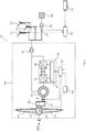
- Fig. 2 shows a total of a wind park 200, the electrical structure of the wind energy installation 100 being particularly emphasized.
- further wind energy installations 201, 202, 203 can be seen, all of which are part of wind farm 200.
- the wind energy installations of the wind farm 200 are connected to a three-phase electrical transmission network 230 via a transfer station 220 and can feed power into this.
- the wind turbines are each via a medium voltage transformer 128, which is shown in Fig. 2 is shown by way of example for the wind energy installation 100, connected to the transfer station 220 and the electrical transmission network 230.
- the rotor 130 of the wind energy installation 100 absorbs a torque from the wind and passes it on via a drive train 121, which includes a gearbox 122, to the rotor of a double-fed asynchronous generator 123, which is set up to convert the kinetic energy absorbed from the wind into electrical energy to convert and feed into the electrical transmission network 230.
- the stator of the generator 123 is connected to the electrical supply network 230 via a three-phase line.
- the rotor of the generator 123 is connected to an AC converter 124 via a three-phase line.
- the AC converter 124 is connected on the network side to the stator of the generator 123 and the electrical supply network 230 via a three-phase line.
- electrical lines are shown in the Fig. 2 shown schematically single-phase.
- the AC converter 124 has a rotor-side converter 125 and a line-side converter 126.
- a DC link is provided between the converters.
- a converter regulator 127 of the AC converter 124 is set up to set a generator torque and thus the power fed in via the stator circuit by regulating the rotor currents in the rotor of the generator 123.
- the converter controller 127 of the AC converter 124 is also set up to set the power fed in via the network-side converter 126.
- the converter controller 127 can specify manipulated variables for currents, voltages, powers and / or the generator torque to the rotor-side and / or the line-side converter 125, 126. Reactive and / or effective variables can be specified for the currents and powers.
- the rotor-side converter 125 sets the rotor currents and thus the generator torque by switching power electronic components.
- the converter controller 127 communicates with a wind turbine controller 129 and receives from the latter in particular a setpoint value for a generator torque or an active power to be output.
- the converter controller 127 provides measured values for currents present on the rotor and mains side and other measured variables to the wind turbine controller 129, which can be used by the latter to determine an available reactive power, that is to say the reactive power that can be provided by the wind turbine.
- the wind energy installation 100 has a speed sensor 161. This can be provided at a point on the drive train 121 that allows the speed of the drive train to be measured, for example on a transmission output shaft that is connected to the rotor of the generator 123.
- Speed values measured by the speed sensor 161 are available as input variables at the wind power plant controller 129.
- variables are present at the wind turbine controller 129, which are detected by means of the sensors of the sensor array 160.
- the wind speed and the wind direction are available as input variables on the wind turbine controller 129.
- Further measured variables such as, for example, the network frequency or the network voltage, are also available as input variables to the wind power installation controller 129 and are taken into account by it when the installation is controlled. These variables can also be taken into account when determining the available reactive power.
- the nacelle 120 of the wind power plant and thus its rotor 130 can be aligned with respect to the wind direction via an azimuth displacement device (not shown).
- the wind power plant controller 129 is also connected to a rotor blade angle adjusting device 151, by means of which the wind power plant controller 129 controls the pitch angles of the rotor blades 150.
- the wind energy installation controller 129 generally serves to regulate the operation of the wind energy installation 100.
- the wind power plant controller 129 can be designed, for example, as a programmable logic controller (PLC) and have software for regulating the wind power plant.
- PLC programmable logic controller
- the wind turbine controller 129 receives signals and control commands from a wind farm controller 210, with which it communicates via a data line.
- the wind farm controller 210 receives signals from the wind turbine controller 129 which serve as input variables for regulating the wind farm, for example information about the active and reactive power currently fed in and information about the available active and reactive power.
- the wind farm controller 210 is set up as a higher-level control unit to at least partially execute at least one of the methods according to the invention.
- the wind farm controller 210 sends signals for regulating the wind farm 200 to the individual wind energy installations 100, 201, 202, 203 or their wind energy installation controllers.
- the wind farm controller 210 can be designed, for example, as a programmable logic controller (PLC) and have software for regulating the wind farm.
- PLC programmable logic controller
- the wind farm controller 210 is connected via a data line to an external control device 211, for example a network control center, and receives from this setpoint specifications for the power to be fed in from the wind farm or the power factor to be set for this power.
- the wind farm controller 210 is set up to adjust the power output of the wind farm as a function of the setpoint values specified by the external control device 211.
- These target value specifications can for example be sent to the external from the wind farm controller 210 on the basis of an Control device 211 reported available power (active power, reactive power, apparent power) of the wind farm and the power requirement of the energy supply network can be specified.
- the power setpoint specification for the wind farm can be carried out by the wind farm controller 210 on the basis of measured values that are recorded by a sensor unit 221 at or near the network connection point of the wind farm and that are present as input variables at the wind farm controller 210.
- the target value specification can be specified based on a measured network frequency, the network voltage and / or the reactive power fed in.
- a corresponding regulation rule is stored in the wind farm controller 210.
- Corresponding methods are known from the prior art.
- measured values for the current output from the wind farm is active power P and reactive power Q is present at the wind farm controller 210th
- a setpoint value for the power factor PF should be specified for the power to be fed in to the wind farm controller 210.
- measured values or input values are understood to mean not only actual measured values, but in particular also those variables that have been calculated from the measured values or combinations of different values. Variables can also be determined as time averages over a suitable period.
- a flow chart can be seen which represents the sequence of one of the methods according to the invention.
- a specified power factor setpoint value PF soll is converted into a reactive power setpoint value Q soll .
- a current active power P ist is used for this, as shown by an arrow.
- the calculated Reactive power setpoint Q soll at reference numeral 320 is regulated to a regulated reactive power setpoint Q soll, reg by means of a current reactive power Q ist.
- This regulated reactive power setpoint value Q soll, reg is then distributed as a control variable to all wind energy installations participating in the method, as can be seen at reference numeral 330.
- the summation takes place over n in each case.
- Other distribution methods can also be combined with the method according to the invention. The method, which is carried out by the wind farm controller 210, can thus already end after this refinement.
- FIG. 3b a flow chart can be seen which shows the sequence of a further method according to the invention.
- the regulated reactive power setpoint Q setpoint , reg - instead of being used directly for the wind energy installations as a control variable - is first converted in step 340 into a set power factor setpoint value PF setpoint , reg .
- PF soll cos (arctan Q soll / P ist ) can be used for this.
- this regulated power factor setpoint value PF setpoint, reg can be specified to the wind energy installations as a control variable according to step 330.
- the established regulated power factor setpoint value PF setpoint, reg can be specified as a setpoint value for all wind energy installations participating in the method.
- the reactive power emitted by the systems is then fed in by the systems depending on the specified power factor and a specified target value for the active power to be delivered.
- FIG. 3c a flow chart can be seen which shows the sequence of a further method according to the invention.
- the regulated power factor setpoint value PF setpoint reg - instead of being specified directly to the wind energy installations as a control variable - is initially acted upon with offsets in step 350 for each of the wind energy installations participating in the method.
- a number of power factor setpoint values PF setpoint, disturbance, n thus arise, which are then specified as default values / control variables for the individual n wind power plants participating in the method in accordance with step 330.
- at least some of the systems can thus receive different power factor setpoints PF soll, stör, n.
- the offsets are randomly specified so that they add up to 0.
- the offsets are specified in such a way that they do not exceed a certain value in each case.
- the value can be based, for example, on the level of the power factor, so that the distribution only contains values that are small compared to the power factor and, for example, amount to a maximum of 20% of the power factor.
- the power factor setpoint can be used over the entire Wind farm can be adhered to better, since due to the control-related discretization occurring control oscillations are minimized, as explained above.
- the distributed offsets are preferably zero, so that the actual power output of the wind farm does not deviate from the specification.
Landscapes
- Engineering & Computer Science (AREA)
- Power Engineering (AREA)
- Supply And Distribution Of Alternating Current (AREA)
Priority Applications (1)
| Application Number | Priority Date | Filing Date | Title |
|---|---|---|---|
| EP20152238.0A EP3852211A1 (fr) | 2020-01-16 | 2020-01-16 | Procédé de régulation de la puissance délivrée d'un parc éolien |
Applications Claiming Priority (1)
| Application Number | Priority Date | Filing Date | Title |
|---|---|---|---|
| EP20152238.0A EP3852211A1 (fr) | 2020-01-16 | 2020-01-16 | Procédé de régulation de la puissance délivrée d'un parc éolien |
Publications (1)
| Publication Number | Publication Date |
|---|---|
| EP3852211A1 true EP3852211A1 (fr) | 2021-07-21 |
Family
ID=69174416
Family Applications (1)
| Application Number | Title | Priority Date | Filing Date |
|---|---|---|---|
| EP20152238.0A Pending EP3852211A1 (fr) | 2020-01-16 | 2020-01-16 | Procédé de régulation de la puissance délivrée d'un parc éolien |
Country Status (1)
| Country | Link |
|---|---|
| EP (1) | EP3852211A1 (fr) |
Citations (5)
| Publication number | Priority date | Publication date | Assignee | Title |
|---|---|---|---|---|
| EP1746285A2 (fr) | 2005-07-20 | 2007-01-24 | General Electric Company | Méthode et dispositif pour le réglage d'un parc d'éoliennes ainsi qu'un parc d'éoliennes |
| US20100025994A1 (en) * | 2008-07-29 | 2010-02-04 | General Electric Company | Intra-area master reactive controller for tightly coupled windfarms |
| DE102009011053A1 (de) * | 2009-03-02 | 2010-09-16 | Btc Business Technology Consulting Ag | Windparkregler |
| US20130093186A1 (en) * | 2007-12-14 | 2013-04-18 | Shinji Arinaga | Wind-power generation system and operation control method therefor |
| US20160237990A1 (en) * | 2015-02-18 | 2016-08-18 | General Electric Company | Determining reactive power capability of a renewable energy system |
-
2020
- 2020-01-16 EP EP20152238.0A patent/EP3852211A1/fr active Pending
Patent Citations (5)
| Publication number | Priority date | Publication date | Assignee | Title |
|---|---|---|---|---|
| EP1746285A2 (fr) | 2005-07-20 | 2007-01-24 | General Electric Company | Méthode et dispositif pour le réglage d'un parc d'éoliennes ainsi qu'un parc d'éoliennes |
| US20130093186A1 (en) * | 2007-12-14 | 2013-04-18 | Shinji Arinaga | Wind-power generation system and operation control method therefor |
| US20100025994A1 (en) * | 2008-07-29 | 2010-02-04 | General Electric Company | Intra-area master reactive controller for tightly coupled windfarms |
| DE102009011053A1 (de) * | 2009-03-02 | 2010-09-16 | Btc Business Technology Consulting Ag | Windparkregler |
| US20160237990A1 (en) * | 2015-02-18 | 2016-08-18 | General Electric Company | Determining reactive power capability of a renewable energy system |
Similar Documents
| Publication | Publication Date | Title |
|---|---|---|
| EP2989708B1 (fr) | Procédé pour injecter de l'énergie électrique dans un réseau d'alimentation électrique | |
| EP2411669B1 (fr) | Procédé de fonctionnement d'un aérogénérateur | |
| EP2093419B1 (fr) | Procédé de régulation d'une éolienne et éolienne | |
| EP3408913B1 (fr) | Procédé d'injection d'énergie électrique dans un réseau d'alimentation électrique | |
| EP2841766B1 (fr) | Parc éolien permettant une régulation locale rapide de la puissance réactive | |
| EP2324551B1 (fr) | Régulation de puissance pour un parc éolien | |
| EP1290343B1 (fr) | Organe d'entrainement azimutal pour eoliennes | |
| EP2244348B1 (fr) | Parc éolien doté de plusieurs éoliennes et procédé de réglage de l'alimentation d'un parc éolien | |
| EP3420222B1 (fr) | Procédé et module de régulation de parc éolien pour la régulation d'un parc éolien | |
| EP3031115B1 (fr) | Procede de commande d'eoliennes | |
| EP3095168B1 (fr) | Méthode de reglage et/ou controle pour l'exploitation d'une centrale éolienne et/ou d'un parc d'éoliennes et centrale éolienne et parc d'éoliennes | |
| EP1892412A1 (fr) | Procédé de fonctionnement d'éoliennes | |
| DE102016007098A1 (de) | Windpark mit schneller Reaktion auf Netzparameteränderungen und Verfahren hierfür | |
| EP2864631A2 (fr) | Parc éolien comprenant plusieurs points d'alimentation du réseau | |
| DE102017011235A1 (de) | Windpark mit autarker Phasenwinkelregelung | |
| EP3754178B1 (fr) | Procédé de fonctionnement d'un parc éolien | |
| DE10023440C1 (de) | Azimutantrieb für Windenergieanlagen | |
| EP3495656B1 (fr) | Procédé de détermination de la dynamique de charge d'une éolienne | |
| EP3852211A1 (fr) | Procédé de régulation de la puissance délivrée d'un parc éolien | |
| EP3909107A1 (fr) | Éolienne | |
| EP3848575A1 (fr) | Procédé de fonctionnement d'un parc éolien comprenant plusieurs éoliennes ainsi que parc éolien correspondant | |
| EP3887676B1 (fr) | Procédé permettant de faire fonctionner une éolienne | |
| EP3021448B1 (fr) | Éolienne, procede de fonctionnement d'une eolienne | |
| EP3852214A1 (fr) | Procédé de commande d'une éolienne | |
| EP4074960A1 (fr) | Procédé de fonctionnement d'une ferme éolienne et ferme éolienne |
Legal Events
| Date | Code | Title | Description |
|---|---|---|---|
| PUAI | Public reference made under article 153(3) epc to a published international application that has entered the european phase |
Free format text: ORIGINAL CODE: 0009012 |
|
| STAA | Information on the status of an ep patent application or granted ep patent |
Free format text: STATUS: THE APPLICATION HAS BEEN PUBLISHED |
|
| AK | Designated contracting states |
Kind code of ref document: A1 Designated state(s): AL AT BE BG CH CY CZ DE DK EE ES FI FR GB GR HR HU IE IS IT LI LT LU LV MC MK MT NL NO PL PT RO RS SE SI SK SM TR |
|
| STAA | Information on the status of an ep patent application or granted ep patent |
Free format text: STATUS: REQUEST FOR EXAMINATION WAS MADE |
|
| 17P | Request for examination filed |
Effective date: 20220119 |
|
| RBV | Designated contracting states (corrected) |
Designated state(s): AL AT BE BG CH CY CZ DE DK EE ES FI FR GB GR HR HU IE IS IT LI LT LU LV MC MK MT NL NO PL PT RO RS SE SI SK SM TR |
|
| STAA | Information on the status of an ep patent application or granted ep patent |
Free format text: STATUS: EXAMINATION IS IN PROGRESS |
|
| 17Q | First examination report despatched |
Effective date: 20240522 |