EP3852246B1 - Kontakteinrichtung eines stators, stator und elektrische maschine - Google Patents
Kontakteinrichtung eines stators, stator und elektrische maschine Download PDFInfo
- Publication number
- EP3852246B1 EP3852246B1 EP20000479.4A EP20000479A EP3852246B1 EP 3852246 B1 EP3852246 B1 EP 3852246B1 EP 20000479 A EP20000479 A EP 20000479A EP 3852246 B1 EP3852246 B1 EP 3852246B1
- Authority
- EP
- European Patent Office
- Prior art keywords
- conductor
- stator
- coil
- contact
- contact device
- Prior art date
- Legal status (The legal status is an assumption and is not a legal conclusion. Google has not performed a legal analysis and makes no representation as to the accuracy of the status listed.)
- Active
Links
Images

Classifications
-
- H—ELECTRICITY
- H02—GENERATION; CONVERSION OR DISTRIBUTION OF ELECTRIC POWER
- H02K—DYNAMO-ELECTRIC MACHINES
- H02K3/00—Details of windings
- H02K3/46—Fastening of windings on the stator or rotor structure
-
- H—ELECTRICITY
- H02—GENERATION; CONVERSION OR DISTRIBUTION OF ELECTRIC POWER
- H02K—DYNAMO-ELECTRIC MACHINES
- H02K5/00—Casings; Enclosures; Supports
- H02K5/04—Casings or enclosures characterised by the shape, form or construction thereof
- H02K5/22—Auxiliary parts of casings not covered by groups H02K5/06-H02K5/20, e.g. shaped to form connection boxes or terminal boxes
- H02K5/225—Terminal boxes or connection arrangements
-
- H—ELECTRICITY
- H02—GENERATION; CONVERSION OR DISTRIBUTION OF ELECTRIC POWER
- H02K—DYNAMO-ELECTRIC MACHINES
- H02K3/00—Details of windings
- H02K3/46—Fastening of windings on the stator or rotor structure
- H02K3/52—Fastening salient pole windings or connections thereto
- H02K3/521—Fastening salient pole windings or connections thereto applicable to stators only
- H02K3/522—Fastening salient pole windings or connections thereto applicable to stators only for generally annular cores with salient poles
-
- H—ELECTRICITY
- H01—ELECTRIC ELEMENTS
- H01R—ELECTRICALLY-CONDUCTIVE CONNECTIONS; STRUCTURAL ASSOCIATIONS OF A PLURALITY OF MUTUALLY-INSULATED ELECTRICAL CONNECTING ELEMENTS; COUPLING DEVICES; CURRENT COLLECTORS
- H01R4/00—Electrically-conductive connections between two or more conductive members in direct contact, i.e. touching one another; Means for effecting or maintaining such contact; Electrically-conductive connections having two or more spaced connecting locations for conductors and using contact members penetrating insulation
- H01R4/10—Electrically-conductive connections between two or more conductive members in direct contact, i.e. touching one another; Means for effecting or maintaining such contact; Electrically-conductive connections having two or more spaced connecting locations for conductors and using contact members penetrating insulation effected solely by twisting, wrapping, bending, crimping, or other permanent deformation
- H01R4/18—Electrically-conductive connections between two or more conductive members in direct contact, i.e. touching one another; Means for effecting or maintaining such contact; Electrically-conductive connections having two or more spaced connecting locations for conductors and using contact members penetrating insulation effected solely by twisting, wrapping, bending, crimping, or other permanent deformation by crimping
- H01R4/182—Electrically-conductive connections between two or more conductive members in direct contact, i.e. touching one another; Means for effecting or maintaining such contact; Electrically-conductive connections having two or more spaced connecting locations for conductors and using contact members penetrating insulation effected solely by twisting, wrapping, bending, crimping, or other permanent deformation by crimping for flat conductive elements, e.g. flat cables
-
- H—ELECTRICITY
- H02—GENERATION; CONVERSION OR DISTRIBUTION OF ELECTRIC POWER
- H02K—DYNAMO-ELECTRIC MACHINES
- H02K1/00—Details of the magnetic circuit
- H02K1/06—Details of the magnetic circuit characterised by the shape, form or construction
- H02K1/12—Stationary parts of the magnetic circuit
-
- H—ELECTRICITY
- H02—GENERATION; CONVERSION OR DISTRIBUTION OF ELECTRIC POWER
- H02K—DYNAMO-ELECTRIC MACHINES
- H02K1/00—Details of the magnetic circuit
- H02K1/06—Details of the magnetic circuit characterised by the shape, form or construction
- H02K1/12—Stationary parts of the magnetic circuit
- H02K1/16—Stator cores with slots for windings
-
- H—ELECTRICITY
- H02—GENERATION; CONVERSION OR DISTRIBUTION OF ELECTRIC POWER
- H02K—DYNAMO-ELECTRIC MACHINES
- H02K3/00—Details of windings
- H02K3/04—Windings characterised by the conductor shape, form or construction, e.g. with bar conductors
- H02K3/28—Layout of windings or of connections between windings
-
- H—ELECTRICITY
- H02—GENERATION; CONVERSION OR DISTRIBUTION OF ELECTRIC POWER
- H02K—DYNAMO-ELECTRIC MACHINES
- H02K3/00—Details of windings
- H02K3/46—Fastening of windings on the stator or rotor structure
- H02K3/50—Fastening of winding heads, equalising connectors, or connections thereto
-
- H—ELECTRICITY
- H02—GENERATION; CONVERSION OR DISTRIBUTION OF ELECTRIC POWER
- H02K—DYNAMO-ELECTRIC MACHINES
- H02K3/00—Details of windings
- H02K3/46—Fastening of windings on the stator or rotor structure
- H02K3/52—Fastening salient pole windings or connections thereto
- H02K3/521—Fastening salient pole windings or connections thereto applicable to stators only
-
- H—ELECTRICITY
- H01—ELECTRIC ELEMENTS
- H01R—ELECTRICALLY-CONDUCTIVE CONNECTIONS; STRUCTURAL ASSOCIATIONS OF A PLURALITY OF MUTUALLY-INSULATED ELECTRICAL CONNECTING ELEMENTS; COUPLING DEVICES; CURRENT COLLECTORS
- H01R2201/00—Connectors or connections adapted for particular applications
- H01R2201/10—Connectors or connections adapted for particular applications for dynamoelectric machines
-
- H—ELECTRICITY
- H01—ELECTRIC ELEMENTS
- H01R—ELECTRICALLY-CONDUCTIVE CONNECTIONS; STRUCTURAL ASSOCIATIONS OF A PLURALITY OF MUTUALLY-INSULATED ELECTRICAL CONNECTING ELEMENTS; COUPLING DEVICES; CURRENT COLLECTORS
- H01R4/00—Electrically-conductive connections between two or more conductive members in direct contact, i.e. touching one another; Means for effecting or maintaining such contact; Electrically-conductive connections having two or more spaced connecting locations for conductors and using contact members penetrating insulation
- H01R4/02—Soldered or welded connections
- H01R4/023—Soldered or welded connections between cables or wires and terminals
-
- H—ELECTRICITY
- H02—GENERATION; CONVERSION OR DISTRIBUTION OF ELECTRIC POWER
- H02K—DYNAMO-ELECTRIC MACHINES
- H02K2203/00—Specific aspects not provided for in the other groups of this subclass relating to the windings
- H02K2203/03—Machines characterised by the wiring boards, i.e. printed circuit boards or similar structures for connecting the winding terminations
-
- H—ELECTRICITY
- H02—GENERATION; CONVERSION OR DISTRIBUTION OF ELECTRIC POWER
- H02K—DYNAMO-ELECTRIC MACHINES
- H02K2203/00—Specific aspects not provided for in the other groups of this subclass relating to the windings
- H02K2203/09—Machines characterised by wiring elements other than wires, e.g. bus rings, for connecting the winding terminations
Definitions
- the invention relates to a contact device for a stator of an electrical machine according to the preamble of claim 1 as well as to a stator and an electrical machine.
- Electric motors for example, as three-phase machines, have a stator with three phases and thus at least three phase conductors or phase windings, each of which is supplied with electrical current in a phase-shifted manner in order to generate a magnetic rotating field in which a rotor or runner, usually provided with permanent magnets, rotates.
- the phase ends of the phase windings are led to motor electronics via phase connections to control the electric motor.
- the coils are connected to one another in a suitable manner via the coil ends of the phase windings. The type of connection of the coil ends is determined by the winding pattern of the rotating field winding.
- Such a contact device has, for example, a laying ring and a connection ring that can be placed on top of it, between which the coil ends to be connected are located.
- the contact device In order to connect different winding schemes in a suitable and flexible manner in practice, it is planned, for example, to design the contact device as a modular assembly, so that a different contact device is placed on the stator depending on the application and the desired connection. In particular in applications in which a single or multiple redundant connection of the rotating field winding is desired, such a modular contact device requires a lot of installation space.
- a contact device in a stator of an electrical machine which has an annular contact carrier made of electrically insulating material and electrical conductor tracks for contacting the coils of the stator.
- the conductor tracks are held on the contact carrier by formed fastening elements.
- the publication EN 20 2010 017 081 U1 discloses a contact device for a stator of an electrical machine.
- On the radial outer edge of a contact carrier outwardly open receiving grooves for the ends of coil wires are arranged.
- the receiving grooves extend in the axial direction. They serve to position the ends of the coil wires so that they come into contact with contact sections of conductor tracks.
- the receiving grooves are designed as simple recesses in the material of the contact carrier.
- An associated contact device comprises a laying element placed on the front side of the stator laminated core and a connection element for connecting the coil ends to phase connections on a stator front side.
- the coil ends protrude vertically through through-openings of the laying element and are each radially angled along a guide groove of the laying element At a contact point in the guide groove, these coil ends are axially contacted and fixed by means of a contact element that is electrically conductively coupled to the interconnection element.
- the guide grooves each have a narrow point in the axial direction, which secures the coil end guided in the guide groove against axial slipping out.
- the publication CN 208 806 679 U discloses an electric motor with a special device that protects against corrosion.
- certain parts of the motor front end cover, stator core and rear end cover
- the electric motor has a fastening ring with a self-locking structure.
- This self-locking structure includes fixing devices that are designed to prevent the end of the conductor from moving in the direction of the conductor axis, thus fixing the conductor axially.
- the invention is based on the object of developing a contact device for a stator of an electrical machine.
- the invention is represented with respect to a contact device by the features of claim 1, with respect to a stator by claim 9 and with respect to an electrical machine by claim 10.
- the further dependent claims relate to advantageous embodiments and developments of the invention.
- the invention includes a contact device for a stator of an electrical machine, wherein the contact device comprises a contact carrier made of electrically insulating material, an upper side which can be positioned facing away from the stator, and at least on the upper side facing away from the stator, electrically conductive connecting conductors for contacting a plurality of coils arranged over the circumference of the stator via coil conductors.
- the contact device also has through-openings through which the coil conductors of the coils can be passed through such that at least one coil conductor can be connected to a connecting conductor. In particular, one coil conductor can be connected to one connecting conductor.
- the contact carrier has fixing devices in the form of elastic retaining lugs on and/or in the through-openings, which are designed such that at least one coil conductor passed through a through-opening touches a connecting conductor on a contact surface and the coil conductor exerts a permanent force on the connecting conductor on this contact surface by forces acting perpendicular to the respective conductor axis.
- fixing devices in the form of elastic retaining lugs on and/or in the through-openings, which are designed such that at least one coil conductor passed through a through-opening touches a connecting conductor on a contact surface and the coil conductor exerts a permanent force on the connecting conductor on this contact surface by forces acting perpendicular to the respective conductor axis.
- the contact device according to the invention can preferably be used in a stator of an electrical machine such as a generator or an electric motor.
- Areas of application include, for example, motors in the automotive sector or in applications in general mechanical engineering and drive technology. For example, in servo motors, drive motors or auxiliary units in vehicles.
- the invention is based on the idea that the contact carrier made of an insulating material can be placed on the front side of the stator and connected to the stator housing.
- the contact carrier is therefore used on the one hand to attach the contact device to the stator and on the other hand as a carrier for the conductor tracks of the connecting conductors. Due to the design of the contact carrier, various conductor tracks on the contact carrier are made of electrically insulating material and are electrically insulated from one another.
- the contact carriers are often very complex in construction, in principle a single ring-shaped contact carrier on which the conductor tracks of the connecting conductors are arranged is sufficient.
- the contact device can be used to electrically connect the coils in the stator via coil lines.
- the contact device comprises a contact carrier, usually in the form of a ring, made of electrically insulating material, as well as electrically conductive conductor tracks as connecting conductors for contacting the winding wire of the coils.
- the conductor tracks, winding wires of the coils and the coil conductors can have a round, oval, rectangular or even square cross-section perpendicular to their conductor axis.
- the coil conductors are electrically conductively and preferably firmly connected to the connecting conductors.
- Suitable Material-locking connections between the coil conductors and connecting conductors lying next to each other at their respective ends are, for example, welded joints or soldered joints.
- the contact carrier made of electrically insulating material, which is preferably ring-shaped, initially serves as a positioning element when laying and connecting the conductor ends.
- the coil conductors are pushed through the through-openings.
- the through-openings have fixing devices which hold the connecting conductors in place at least by frictional engagement and/or material bonding.
- the fixing devices are elastically deformable narrow passages which are arranged in the through-openings. The elastic behavior of the narrow point causes the connection to be held in place when a coil conductor is contacted with a connecting conductor of the contact device, for example by a plug connection or by material bonding through a welded or soldered connection.
- the holding of the coil conductors already causes the cable ends to be fixed before welding or soldering, whereby the respective coil conductors are precisely positioned relative to one another in relation to the respective connecting conductor to produce a joint connection.
- the coil conductors exert a permanent force on the connecting conductors at the contact surface and can create secure electrical connections without any additional holding means if necessary.
- the contact carriers are equipped with fixing devices at the through-openings, which enable the two conductor ends to be positioned in a targeted manner.
- the conductor sections lying parallel to one another, in particular conductor ends are pressed together at the common contact surface by forces acting perpendicular to the respective conductor axis. This force is particularly present during the joining process to create good electrical contact and is advantageously also present after the Connecting the conductor ends is still permanent.
- a particular advantage is that simply by pressing the coil conductor and the connecting conductor together, a reliable and permanent electrical contact is created that is not subject to tensile stresses.
- the contact carrier can be designed with fixing devices at the through-openings in such a way that these lock the coil conductors against axial movement in at least one direction.
- the fixing devices are preferably designed in such a way that the coil conductors are held in place at least against the direction of insertion by frictional engagement or material bonding.
- the direction of insertion is the direction starting from the underside of the contact carrier facing the coils to the top side on which the connecting conductors are located.
- Elastically deformable narrow passages are created as a fixing device, which reliably counteract the backward movement of the respective conductor end. The elastic behavior of the narrow point causes the fixing even before a coil conductor is connected to a connecting conductor of the contact device, for example by a plug connection or materially bonded by a welded or soldered connection.
- the fixing device is formed by elastic retaining lugs.
- elastically deformable retaining lugs form a narrow point, the opening width of which is smaller than the diameter of the coil conductors. These narrow the cross-section in such a way that the fixing device fixes the respective conductor ends like a gripping mechanism.
- the elastically deformable material only widens the opening width when a conductor end passes through, thus creating a perpendicular to the axial direction of the conductor and/or simultaneously generates a holding force axially.
- Plastics with corresponding elastic properties are suitable materials.
- the holding lugs can also be made of the same material as the contact carrier.
- retaining lugs can be arranged in at least one through-opening.
- the retaining lugs can be arranged in a through-opening plane and/or staggered and/or offset in the axial direction of the through-opening through the contact carrier.
- the retaining lugs are arranged in such a way that they result in a permanent force effect of the coil conductors on the common contact surface on the connecting conductors.
- the retaining lugs can also prevent the respective conductor end from moving back against the insertion direction. With a square or rectangular conductor cross-section, it is advantageous to use four retaining lugs on the four conductor surfaces.
- the retaining lugs can form a positive connection with the coil conductor.
- the conductor section passing through the through-opening can have a suitable roughness or another structure on its surface, which forms a positive connection with the retaining lugs.
- Structurally advantageous are notches, indentations or serrations on the conductor surface of a coil conductor, into which the retaining lugs can engage.
- the retaining lugs can form a material connection with the coil conductor.
- Thermal connection methods such as welding or soldering can be used for this.
- the fixing device can be arranged in the direction of insertion of the coil conductors at the output end of the through-opening.
- the conductor end is first inserted into the through-opening and is already guided so stably at the output end that it can pass through the fixing device.
- the through-openings can taper conically in the direction in which the coil conductors are inserted.
- a conical shape of the through-opening requires a larger opening on the input side into which a conductor end of a coil conductor can be easily inserted, whereby the conductor end is guided to the output end by the tapering conical shape when inserted.
- a further aspect of the invention includes a stator of an electrical machine with a contact device according to the invention.
- a further aspect of the invention includes an electrical machine with a stator according to the invention.
- the above-mentioned stator with the contact unit according to the invention can be an independent module unit of an electrical machine.
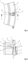
- FIG.1 A stator 2 with a contact device 1 attached to the front is shown schematically.
- the connection contacts arranged on the top of a contact carrier 4 are combined in a plug, which is to be connected to the electrical connection.
- This contact device 1 is in Fig. 2 shown as a partial section.
- Fig.2 shows schematically a detailed view of a contact device 1 in the area of a contact point of a coil conductor 31 with a connecting conductor 41.
- the coil 3 is in the Figure 2 not shown in detail, but arranged in the direction of the arrow.
- the coil conductor 31 and the connecting conductor 41 have a rectangular cross-section perpendicular to their respective conductor axis. Due to the rectangular cross-sections, the coil conductor 31 and the connecting conductor 41 touch at a common contact surface 7. The end of the coil conductor 31 passes through a through-opening in the contact carrier 4.
- a fixing device 6 with retaining lugs 61 is formed at the output end of the through-opening.
- These retaining lugs 61 narrow the cross-section in such a way that the fixing device 6 acts like a gripping mechanism on the respective coil conductor 31.
- the retaining lugs 61 are also made of the same material as that of the contact carrier 4.
- the coil conductors 31 When the coil conductors 31 are assembled, they are pushed through the narrow point specified by the fixing device 6 and the retaining lugs 61 are essentially pre-tensioned. This creates a force effect through which the coil conductors 31 exert a permanent force on the connecting conductors 41 on the common contact surface 7.
- the coil conductors 31 and the connecting conductors 41 are already electrically connected by the contact force and are also joined in a materially bonded manner at least in sections or over the entire common contact surface 7, for example via solder or welded connections.
- the contact force between the coil conductor 31 and the connecting conductor 41 can also be used to create a reliable electrical contact in the case of plug contacts.
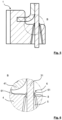
- Fig.3 shows a plan view of a partial section of a contact device 1.
- Fig.4 is a cross section along the line AA from Figure 3
- the coil conductor 31 and the connecting conductor 41 touch each other at a common contact surface 7.
- a joint connection can take place at this contact surface 7.
- the end of the coil conductor 31 passes through a through-opening 5 in the contact carrier 4.
- the through-opening 5 has a larger opening width at the input end 9 than at the output end 8 and thus tapers conically in the direction of insertion of the coil conductor 31.
- the conical shape of the through-opening 5 makes it easier to insert the conductor end of a coil conductor 31 through the through-opening 5, whereby the conductor end The insertion is guided through the tapered conical path to the output end 8 in the fixing device 6.
- the fixing device 6 is arranged with its retaining lugs 61 directly at the output end 8. In this way, the conductor end of the respective coil conductor 31 is guided through the fixing device 6 until it is positioned on the connecting conductor 41.
- Fig.5 shows a cross section of a section of a contact device 1.
- Fig.6 is a detailed view of the fixing device 6 from Figure 5
- the retaining lugs 61 of the fixing device 6 arranged at the output end 8 are elastically deformed and prestressed in the insertion direction by the coil conductor 31 pushed through. These upwardly bent retaining lugs 61 counteract a backward movement of the respective conductor end of the coil conductor 31.
- the elastic behavior of the constriction causes the fixing even before the associated connecting conductor 41 is firmly connected to the coil conductor 31 by a welded or soldered connection.
Landscapes
- Engineering & Computer Science (AREA)
- Power Engineering (AREA)
- Insulation, Fastening Of Motor, Generator Windings (AREA)
Description
- Die Erfindung betrifft eine Kontakteinrichtung für einen Stator einer elektrischen Maschine gemäß dem Oberbegriff des Anspruchs 1 sowie einen Stator und eine elektrische Maschine.
- Elektromotoren weisen beispielsweise als dreiphasige Drehstrommaschinen einen Stator mit drei Phasen und damit zumindest drei Phasenleiter oder Phasenwicklungen auf, die jeweils phasenversetzt mit elektrischem Strom beaufschlagt werden, um ein magnetisches Drehfeld zu erzeugen, in dem ein üblicherweise mit Permanentmagneten versehener Rotor oder Läufer rotiert. Die Phasenenden der Phasenwicklungen werden zur Ansteuerung des Elektromotors über Phasenanschlüsse an eine Motorelektronik geführt. Die Spulen werden über die Spulenenden der Phasenwicklungen in geeigneter Weise miteinander verschaltet. Die Art der Verschaltung der Spulenenden ist durch das Wicklungsschema der Drehfeldwicklung bestimmt.
- Zur Führung und Verschaltung der Spulenenden sind Kontakteinrichtungen üblich, die stirnseitig auf den Stator aufgesetzt werden. Eine derartige Kontakteinrichtung weist beispielsweise einen Verlegering und einen darauf aufsetzbaren Verschaltungsring auf, zwischen denen die zu verschaltenden Spulenenden liegen.
- Um in der Praxis unterschiedliche Wicklungsschemata geeignet und flexibel anzuschließen, ist es beispielsweise angedacht, die Kontakteinrichtung als eine modulare Baugruppe auszuführen, sodass je nach Anwendung und gewünschter Verschaltung eine unterschiedliche Kontaktiereinrichtung auf den Stator aufgesetzt wird. Insbesondere bei Anwendungen, in welchen eine einfach oder mehrfach redundante Verschaltung der Drehfeldwicklung gewünscht ist, weist eine derartige modulare Kontaktiereinrichtung einen hohen Bauraumbedarf auf.
- Aus der Druckschrift
EP 2 606 558 A1 ist eine Kontakteinrichtung in einem Stator einer elektrischen Maschine bekannt, welcher einen ringförmigen Kontaktträger aus elektrisch isolierendem Material sowie elektrische Leitungsbahnen zur Kontaktierung der Spulen des Stators aufweist. Die Leitungsbahnen sind über umgeformte Befestigungselemente am Kontaktträger gehalten. - Die Druckschrift
DE 20 2010 017 081 U1 offenbart eine Kontakteinrichtung für einen Stator einer elektrischen Maschine. An der radialen Außenkante eines Kontaktträgers sind nach außen offene Aufnahmenuten für die Enden von Spulendrähten angeordnet. Die Aufnahmenuten erstrecken sich in Achsrichtung. Sie dienen dazu, die Enden der Spulendrähte so zu positionieren, dass diese in Kontakt mit Kontaktabschnitten von Leitungsbahnen kommen. Zu diesem Zweck sind die Aufnahmenuten als einfache Aussparungen im Material des Kontaktträgers ausgebildet. - Des Weiteren ist aus der Druckschrift
DE 10 2016 224 526 A1 ein Stator einer elektrischen Maschine mit einem Statorblechpaket bekannt. Eine zugehörige Kontakteinrichtung umfasst ein stirnseitig auf das Statorblechpaket aufgesetztes Verlegeelement sowie ein Verschaltungselement für die Verschaltung der Spulenenden mit Phasenanschlüssen an einer Statorstirnseite. Die Spulenenden ragen senkrecht durch Durchführöffnungen des Verlegeelements hindurch und sind jeweils radial abgewinkelt entlang einer Führungsnut des Verlegeelements geführt. An einer Kontaktstelle der Führungsnut sind diese Spulenenden mittels eines mit dem Verschaltungselement elektrisch leitfähig gekoppelten Kontaktelements axial kontaktiert und fixiert. Die Führungsnuten weisen in Axialrichtung jeweils eine Engstelle auf, welche das jeweils in der Führungsnut geführte Spulenende gegen ein axiales Herausgleiten sichert. - Die Druckschrift
CN 208 806 679 U offenbart einen elektrischen Motor mit einer speziellen Einrichtung, die vor Korrosion schützt. Zu diesem Zweck werden bestimmte Teile des Motors (vordere Endabdeckung, Statorkern und hintere Endabdeckung) durch einen Leiter verbunden, so dass diese Teile auf dem gleichen elektrischen Potenzial liegen. Um die Zuverlässigkeit dieses Korrosionsschutzes zu verbessern, weist der elektrische Motor einen Befestigungsring mit einer selbst-sichernden Struktur auf. Diese selbst-sichernde Struktur umfasst Fixiereinrichtungen, die so ausgebildet sind, dass sie das Ende des Leiters gegen ein Verschieben in Richtung der Leiterachse verhindern, den Leiter also axial fixieren. - Der Erfindung liegt die Aufgabe zugrunde, eine Kontakteinrichtung für einen Stator einer elektrischen Maschine weiterzubilden.
- Die Erfindung wird bezüglich einer Kontakteinrichtung durch die Merkmale des Anspruchs 1, bezüglich eines Stators durch Anspruch 9 und bezüglich einer elektrischen Maschine durch Anspruch 10 wiedergegeben. Die weiteren rückbezogenen Ansprüche betreffen vorteilhafte Aus- und Weiterbildungen der Erfindung.
- Die Erfindung schließt eine Kontakteinrichtung für einen Stator einer elektrischen Maschine ein, wobei die Kontakteinrichtung einen Kontaktträger aus elektrisch isolierendem Material, eine Oberseite, die vom Stator abgewandt positionierbar ist, sowie zumindest auf der vom Stator abgewandten Oberseite elektrisch leitende Anschlussleiter zur Kontaktierung einer Mehrzahl von über dem Umfang des Stators angeordneten Spulen über Spulenleiter aufweist. Ferner weist die Kontakteinrichtung Durchführöffnungen auf, durch die die Spulenleiter der Spulen so durchführbar sind, dass mindestens ein Spulenleiter mit einem Anschlussleiter verbindbar ist. Insbesondere kann jeweils ein Spulenleiter mit jeweils einem Anschlussleiter verbindbar sein. Zudem weist der Kontaktträger an und/oder in den Durchführöffnungen Fixiereinrichtungen in Form von elastischen Haltenasen auf, die derart ausgebildet sind, dass mindestens ein durch eine Durchführöffnung durchgeführter Spulenleiter einen Anschlussleiter an einer Kontaktfläche berührt und der Spulenleiter an dieser Kontaktfläche durch senkrecht zur jeweiligen Leiterachse wirkende Kräfte eine permanente Kraftwirkung auf den Anschlussleiter ausübt. Dadurch ist es möglich, dass zueinander parallel liegende Abschnitte des Spulenleiters und des Anschlussleiters, insbesondere jeweils zueinander parallel liegende Enden der Spulenleiter und der Anschlussleiter, an der gemeinsamen Kontaktfläche aneinander gepresst werden.
- Die erfindungsgemäße Kontakteinrichtung kann bevorzugt in einem Stator einer elektrischen Maschine wie einem Generator oder einem Elektromotor eingesetzt werden. Anwendungsgebiete sind beispielsweise Motoren im Automotivbereich oder in Anwendungen im allgemeinen Maschinenbau und der Antriebstechnik. Beispielsweise bei Servomotoren, Antriebsmotoren oder Hilfsaggregate in Fahrzeugen.
- Die Erfindung geht dabei von der Überlegung aus, dass der aus einem isolierenden Material hergestellte Kontaktträger auf die Stirnseite des Stators aufgesetzt und mit dem Statorgehäuse verbunden werden kann. Der Kontaktträger dient somit zum einen zur Befestigung der Kontakteinrichtung am Stator und zum anderen als Träger der Leitungsbahnen der Anschlussleiter. Aufgrund der Ausführungsweise des Kontaktträgers sind aus elektrisch isolierendem Material verschiedene Leitungsbahnen auf dem Kontaktträger elektrisch voneinander isoliert. Obwohl die Kontaktträger oft bereits sehr komplex aufgebaut sind, genügt prinzipiell auch ein einziger ringförmiger Kontaktträger, an dem die Leitungsbahnen der Anschlussleiter angeordnet sind.
- Über die Kontakteinrichtung können die Spulen im Stator über Spulenleitungen elektrisch angebunden werden. Die Kontakteinrichtung umfasst einen meist ringförmigen Kontaktträger aus elektrisch isolierendem Material sowie elektrisch leitende Leitungsbahnen als Anschlussleiter zur Kontaktierung des Wicklungsdrahtes der Spulen. Die Leitungsbahnen, Wicklungsdrähte der Spulen und die Spulenleiter können einen runden, ovalen, rechteckigen oder auch quadratischen Querschnitt senkrecht zu ihrer Leiterachse aufweisen.
- Um die Spulenleiter der Spulen mit den Anschlussleitern zur elektrischen Kontaktierung zu verbinden ist es von Vorteil, dass diese an der Verbindungsstelle einen gleichgearteten rechteckigen oder auch quadratischen Querschnitt aufweisen. Dadurch berühren sich die Spulenleiter und die Anschlussleiter an einer flächig ausgebildeten und maximierten Kontaktfläche.
- Im Bereich dieser Kontaktfläche sind die Spulenleiter mit den Anschlussleitern elektrisch leitend und bevorzugt stoffschlüssig verbunden. Geeignete stoffschlüssige Verbindungen der an jeweiligen Enden aneinander liegenden Spulenleiter und Anschlussleiter sind beispielsweise Schweißverbindungen oder Lötverbindungen.
- Der Kontaktträger aus elektrisch isolierendem Material, der bevorzugt ringförmig ausgeführt ist, dient zunächst als Positionierelement beim Verlegen und Verbinden der Leiterenden. Hierzu werden die Spulenleiter durch die Durchführöffnungen geschoben. Die Durchführöffnungen weisen Fixiereinrichtungen auf, welche die Anschlussleiter zumindest durch Reibschluss und/oder Stoffschluss festhalten. Mit anderen Worten: Die Fixiereinrichtungen sind elastisch verformbare enge Durchtrittsstellen, welche in den Durchführöffnungen angeordnet sind. Das elastische Verhalten der Engstelle bewirkt das Festhalten, wenn ein Spulenleiter mit einem Anschlussleiter der Kontakteinrichtung beispielsweise durch eine Steckverbindung oder stoffschlüssig durch eine Schweiß- oder Lötverbindung kontaktiert wird. Bei Schweiß- oder Lötverbindungen bewirkt das Festhalten der Spulenleiter bereits ein Fixieren der Kabelenden vor dem Schweißen oder Löten, wodurch die jeweiligen Spulenleiter zum jeweiligen Anschlussleiter zur Herstellung einer Fügeverbindung präzise zueinander positioniert sind.
- Die Spulenleiter üben an der Kontaktfläche eine permanente Kraftwirkung auf die Anschlussleiter aus und können sichere elektrische Verbindungen gegebenenfalls bereits ohne weitere Haltemittel herstellen. Zur Erzeugung der Kraftwirkung sind die Kontaktträger an den Durchführöffnungen mit Fixiereinrichtungen ausgestattet, die eine gezielte Positionierung beider Leiterenden zueinander ermöglicht. Hierdurch werden die zueinander parallel liegenden Leiterabschnitte, insbesondere Leiterenden, durch senkrecht zur jeweiligen Leiterachse wirkenden Kräfte an der gemeinsamen Kontaktfläche aneinandergepresst. Diese Kraftwirkung ist insbesondere beim Fügevorgang zur Herstellung einer guten elektrischen Kontaktierung vorhanden und vorteilhafterweise auch nach dem Verbinden der Leiterenden noch weiterhin dauerhaft ausgebildet.
- Ein besonderer Vorteil besteht darin, dass bereits alleine durch das Aneinanderpressen von Spulenleiter und Anschlussleiter ein zuverlässiger und dauerhafter elektrischer Kontakt vorhanden ist, der nicht auf Zugspannungen belastet wird.
- In bevorzugter Ausgestaltung der Erfindung kann der Kontaktträger an den Durchführöffnungen mit Fixiereinrichtungen derart ausgebildet sein, dass diese die Spulenleiter zumindest in einer Richtung gegenüber einer axialen Bewegung arretieren. Zur Montage werden die Spulenleiter der Spulen durch die Durchführöffnungen geschoben. Die Fixiereinrichtungen sind bevorzugt so ausgeführt, dass die Spulenleiter zumindest entgegen der Einschubrichtung durch Reibschluss oder Stoffschluss festgehalten werden. Die Einschubrichtung ist die Richtung ausgehend von der den Spulen zugewandten Unterseite des Kontaktträgers hin zur Oberseite, auf der sich die Anschlussleiter befinden. Hierbei sind als Fixiereinrichtung elastisch verformbare enge Durchtrittsstellen geschaffen, die einem Zurückbewegen des jeweiligen Leiterendes zuverlässig entgegenwirken. Das elastische Verhalten der Engstelle bewirkt das Fixieren, bereits bevor ein Spulenleiter mit einem Anschlussleiter der Kontakteinrichtung, beispielsweise durch eine Steckverbindung oder stoffschlüssig durch eine Schweiß- oder Lötverbindung, verbunden wird.
- Die Fixiereinrichtung ist durch elastische Haltenasen ausgebildet. Mehrere elastische verformbare Haltenasen bilden so eine Engstelle, deren Öffnungsweite kleiner als der Durchmesser der Spulenleiter ist. Diese verengen den Querschnitt derart, dass die Fixiereinrichtung wie ein Greifmechanismus die jeweiligen Leiterenden fixiert. Durch elastisches verformbares Material wird erst bei Durchtritt eines Leiterendes die Öffnungsweite aufgeweitet und dadurch eine senkrecht zur axialen Richtung des Leiters und/oder gleichzeitig auch axial eine Haltekraft erzeugt. Als Materialien eignen sich Kunststoffe mit entsprechend elastischen Eigenschaften. Insbesondere können die Haltenasen auch aus demselben Material wie das des Kontaktträgers bestehen.
- Prinzipiell ist es auch vorteilhaft, dass in mindestens einer Durchführöffnung mehrere Haltenasen angeordnet sein können. Die Haltenasen können dabei in einer Durchtrittsebene angeordnet sein und/oder auch in axialer Richtung der Durchtrittsöffnung durch den Kontaktträger gestaffelt und/oder versetzt angeordnet sein. In ihrer Gesamtwirkung sind die Haltenasen so angeordnet, dass diese im Ergebnis eine permanente Kraftwirkung der Spulenleiter an der gemeinsamen Kontaktfläche auf die Anschlussleiter ausüben. In ihrer Gesamtheit können die Haltenasen auch ein Zurückbewegen des jeweiligen Leiterendes entgegen der Einschubrichtung verhindern. Bei quadratischem oder rechteckigem Leiterquerschnitt ist es vorteilhaft, mit vier Haltenasen auf die vier Leiteroberflächen anzusetzen.
- Üblicherweise wird zwischen der Fixiereinrichtung und dem durch die Durchführöffnung tretenden Leiterabschnitt ein durch Haftreibung verursachter Kraftschluss ausgebildet. Aber auch anderweitige Fixiermechanismen alleine oder untereinander in Kombination sind angedacht.
- So können bei einer vorteilhaften Ausführungsform der Erfindung die Haltenasen eine formschlüssige Verbindung mit dem Spulenleiter ausbilden. Hierzu kann der durch die Durchführöffnung tretende Leiterabschnitt an dessen Oberfläche eine geeignete Rauheit oder eine anderweitige Struktur aufweisen, welche jeweils mit den Haltenasen einen Formschluss ausbildet. Strukturell vorteilhaft sind Kerbungen, Einbuchtungen oder Zahnungen an der Leiteroberfläche eines Spulenleiters, in welche die Haltenasen eingreifen können.
- Alternativ oder in Kombination können bei einer weiteren vorteilhaften Ausführungsform der Erfindung die Haltenasen eine stoffschlüssige Verbindung mit dem Spulenleiter ausbilden. Hierzu können thermische Verbindungsverfahren, wie beispielsweise Schweißen oder Löten, benutzt werden. Durch einen gezielten Wärmeeintrag bei der Herstellung der elektrischen Kontaktierung kann entlang der Spulenleiter so viel Wärme zur Fixiereinrichtung abfließen, dass diese thermisch an oder aufgeschmolzen wird und so einen stabilen Stoffschluss ausbildet.
- In weiterer vorteilhafter Ausgestaltung der Erfindung kann die Fixiereinrichtung in Einschubrichtung der Spulenleiter am ausgangsseitigen Ende der Durchführöffnung angeordnet sein. Hierbei wird beim Einbringen das Leiterende zuerst in die Durchtrittsöffnung eingeführt und ist bereits am ausgangsseitigen Ende so stabil geführt, dass es durch die Fixiereinrichtung hindurchtreten kann.
- Vorteilhafterweise können sich die Durchführöffnungen in Einschubrichtung der Spulenleiter konisch verjüngen. Eine konische Form der Durchtrittsöffnung bedingt eingangsseitig eine größere Öffnung, in die ein Leiterende eines Spulenleiters leicht eingeschoben werden kann, wobei das Leiterende beim Einbringen durch den sich verjüngenden konischen Verlauf zum ausgangsseitigen Ende geführt wird. Bei derartigen Durchführöffnungen ist es von Vorteil, die Fixiereinrichtung direkt am ausgangsseitigen Ende anzuordnen. Auf diese Weise wird das Leiterende direkt in die Fixiereinrichtung eingeführt.
- Ein weiterer Aspekt der Erfindung schließt einen Stator einer elektrischen Maschine mit einer erfindungsgemäßen Kontakteinrichtung ein.
- Ein weiterer Aspekt der Erfindung schließt eine elektrische Maschine mit einem erfindungsgemäßen Stator ein. Der vorstehend genannte Stator mit der erfindungsgemäßen Kontakteinheit kann eine eigenständige Moduleinheit einer elektrischen Maschine sein.
- Ausführungsbeispiele der Erfindung werden anhand der schematischen Zeichnungen näher erläutert.
- Darin zeigen:
- Fig. 1
- schematisch einen Stator einer elektrischen Maschine mit einer stirnseitig aufgesetzten Kontakteinrichtung,
- Fig. 2
- schematisch eine Detailansicht einer Kontakteinrichtung im Bereich einer Kontaktstelle eines Spulenleiters mit einem Anschlussleiter,
- Fig. 3
- eine Aufsicht auf einen Teilabschnitt einer Kontakteinrichtung,
- Fig. 4
- einen Querschnitt entlang der Linie A-A aus
Figur 3 , - Fig. 5
- einen Querschnitt auf einen Teilabschnitt einer Kontakteinrichtung, und
- Fig. 6
- eine Detailansicht der Fixiereinrichtung aus
Figur 5 . - Einander entsprechende Teile sind in allen Figuren mit denselben Bezugszeichen versehen.
- In
Fig. 1 ist schematisch ein Stator 2 mit stirnseitig aufgesetzter Kontakteinrichtung 1 dargestellt. Die auf der Oberseite eines Kontaktträgers 4 angeordneten Anschlusskontakte sind in einem Stecker zusammengefasst, der mit dem elektrischen Anschluss zu verbinden ist. Diese Kontakteinrichtung 1 ist inFig. 2 als Teilausschnitt dargestellt. -
Fig. 2 zeigt schematisch eine Detailansicht einer Kontakteinrichtung 1 im Bereich einer Kontaktstelle eines Spulenleiters 31 mit einem Anschlussleiter 41. Die Spule 3 ist in derFigur 2 nicht näher dargestellt, jedoch in Pfeilrichtung angeordnet. Der Spulenleiter 31 und der Anschlussleiter 41 weisen einen rechteckigen Querschnitt senkrecht zu ihrer jeweiligen Leiterachse auf. Durch die rechteckigen Querschnitte berühren sich die Spulenleiter 31 und die Anschlussleiter 41 an einer gemeinsamen Kontaktfläche 7. Das Ende des Spulenleiters 31 tritt durch eine Durchführöffnung im Kontaktträger 4 hindurch. - Am ausgangsseitigen Ende der Durchführöffnung ist eine Fixiereinrichtung 6 mit Haltenasen 61 ausgebildet. In diesem Fall handelt es sich um vier elastisch verformbare Haltenasen 61, die jeweils an einer Fläche des rechteckigen Spulenleiters 31 anliegen. Diese Haltenasen 61 verengen den Querschnitt derart, dass die Fixiereinrichtung 6 wie ein Greifmechanismus auf die jeweiligen Spulenleiter 31 wirkt. In diesem Fall bestehen die Haltenasen 61 auch aus demselben Material wie das des Kontaktträgers 4.
- Bei der Montage der Spulenleiter 31 werden diese durch die Fixiereinrichtung 6 vorgegebene Engstelle hindurchgeschoben und dabei die Haltenasen 61 quasi vorgespannt. Hierdurch entsteht eine Kraftwirkung, durch welche die Spulenleiter 31 auf die Anschlussleiter 41 an der gemeinsamen Kontaktfläche 7 eine permanente Kraftwirkung ausüben. Die Spulenleiter 31 und die Anschlussleiter 41 sind bereits durch die Anpresskraft bereits elektrisch leitend verbunden und zudem zumindest an Teilabschnitten oder über die gesamte gemeinsame Kontaktfläche 7, beispielsweise über Lot- oder Schweißverbindungen, stoffschlüssig gefügt. Auch bei Steckkontakten kann die Anpresskraft zwischen dem Spulenleiter 31 und dem Anschlussleiter 41 dazu dienen einen zuverlässigen elektrischen Kontakt zu erzeugen.
-
Fig. 3 zeigt eine Aufsicht auf einen Teilabschnitt einer Kontakteinrichtung 1. InFig. 4 ist ein Querschnitt entlang der Linie A-A ausFigur 3 dargestellt. Der Spulenleiter 31 und der Anschlussleiter 41 berühren sich an einer gemeinsamen Kontaktfläche 7. An dieser Kontaktfläche 7 kann eine Fügeverbindung stattfinden. Das Ende des Spulenleiters 31 tritt durch eine Durchführöffnung 5 im Kontaktträger 4 hindurch. Die Durchführöffnung 5 hat am eingangsseitigen Ende 9 eine größere Öffnungsweite als am ausgangsseitigen Ende 8 und verjüngt sich somit konisch in Einschubrichtung des Spulenleiters 31. Durch eine konische Form der Durchtrittsöffnung 5 lässt sich das Leiterende eines Spulenleiters 31 leichter durch die Durchführöffnung 5 einführen, wobei das Leiterende beim Einbringen durch den sich verjüngenden konischen Verlauf zum ausgangsseitigen Ende 8 in die Fixiereinrichtung 6 geführt wird. Die Fixiereinrichtung 6 ist mit ihren Haltenasen 61 direkt am ausgangsseitigen Ende 8 angeordnet. Auf diese Weise wird das Leiterende des jeweiligen Spulenleiters 31 durch die Fixiereinrichtung 6 bis zur Positionierung am Anschlussleiter 41 gezielt hindurchgeführt. -
Fig. 5 zeigt einen Querschnitt auf einen Teilabschnitt einer Kontakteinrichtung 1. InFig. 6 ist eine Detailansicht der Fixiereinrichtung 6 ausFigur 5 dargestellt. Die am ausgangsseitigen Ende 8 angeordneten Haltenasen 61 der Fixiereinrichtung 6 werden durch den hindurchgeschobenen Spulenleiter 31 in Einschubrichtung elastisch verformt und in Vorspannung versetzt. Diese nach oben gebogenen Haltenasen 61 wirken einem Zurückbewegen des jeweiligen Leiterendes des Spulenleiters 31 entgegen. Das elastische Verhalten der Engstelle bewirkt das Fixieren, bereits bevor der zugehörige Anschlussleiter 41 mit dem Spulenleiter 31 stoffschlüssig durch eine Schweiß- oder Lötverbindung verbunden wird. -
- 1
- Kontakteinrichtung
- 2
- Stator
- 3
- Spule
- 31
- Spulenleiter
- 4
- Kontaktträger
- 41
- Anschlussleiter
- 5
- Durchführöffnung
- 6
- Fixiereinrichtung
- 61
- Haltenase
- 7
- Kontaktfläche
- 8
- ausgangsseitiges Ende
- 9
- eingangsseitiges Ende
Claims (9)
- Kontakteinrichtung (1) für einen Stator (2) einer elektrischen Maschine, wobei die Kontakteinrichtung (1) einen Kontaktträger (4) aus elektrisch isolierendem Material, eine Oberseite, die vom Stator (2) abgewandt positionierbar ist, sowie zumindest auf der vom Stator (2) abgewandt positionierbaren Oberseite elektrisch leitende Anschlussleiter (41) zur Kontaktierung einer Mehrzahl von über dem Umfang des Stators (2) angeordneten Spulen (3) über Spulenleiter (31) aufweist,wobei die Kontakteinrichtung (1) ferner Durchführöffnungen (5) aufweist, durch die die Spulenleiter (31) der Spulen (3) so durchführbar sind, dass mindestens ein Spulenleiter (31) mit einem Anschlussleiter (41) verbindbar ist,wobei der Kontaktträger (4) an und/oder in den Durchführöffnungen (5) Fixiereinrichtungen (6) aufweist, die derart ausgebildet sind, dass mindestens ein durch eine Durchführöffnung (5) durchgeführter Spulenleiter (31) einen Anschlussleiter (41) an einer Kontaktfläche (7) berührt und der Spulenleiter (31) an dieser Kontaktfläche (7) durch senkrecht zur jeweiligen Leiterachse wirkende Kräfte eine permanente Kraftwirkung auf den Anschlussleiter (41) ausübt, wodurch zueinander parallel liegende Abschnitte des Spulenleiters (31) und des Anschlussleiters (41) an der gemeinsamen Kontaktfläche (7) aneinander gepresst werden,dadurch gekennzeichnet, dass die Fixiereinrichtungen (6) durch elastischen Haltenasen (61) ausgebildet sind.
- Kontakteinrichtung (1) nach Anspruch 1, dadurch gekennzeichnet, dass die Fixiereinrichtungen (6) derart ausgebildet sind, dass diese die Spulenleiter (31) zumindest in einer Richtung gegenüber einer axialen Bewegung arretieren.
- Kontakteinrichtung (1) nach Anspruch 1 oder 2, dadurch gekennzeichnet, dass in mindestens einer Durchführöffnung (5) mehrere Haltenasen (61) angeordnet sind.
- Kontakteinrichtung (1) nach einem der Ansprüche 1 bis 3, dadurch gekennzeichnet, dass die Haltenasen (61) eine formschlüssige Verbindung mit dem Spulenleiter (31) ausbilden.
- Kontakteinrichtung (1) nach einem der Ansprüche 1 bis 4, dadurch gekennzeichnet, dass die Haltenasen (61) eine stoffschlüssige Verbindung mit dem Spulenleiter (31) ausbilden.
- Kontakteinrichtung (1) nach einem der Ansprüche 1 bis 5, dadurch gekennzeichnet, dass die Fixiereinrichtung (6) in Einschubrichtung der Spulenleiter (31) am ausgangsseitigen Ende (8) der Durchführöffnung (5) angeordnet ist.
- Kontakteinrichtung (1) nach einem der Ansprüche 1 bis 6, dadurch gekennzeichnet, dass sich die Durchführöffnungen (5) in Einschubrichtung der Spulenleiter (31) konisch verjüngen.
- Stator (2) einer elektrischen Maschine mit einer Kontakteinrichtung (1) nach einem der Ansprüche 1 bis 7.
- Elektrische Maschine mit einem Stator (2) nach Anspruch 8.
Applications Claiming Priority (1)
| Application Number | Priority Date | Filing Date | Title |
|---|---|---|---|
| DE102020000232.3A DE102020000232A1 (de) | 2020-01-16 | 2020-01-16 | Kontakteinrichtung eines Stators, Stator und elektrische Maschine |
Publications (2)
| Publication Number | Publication Date |
|---|---|
| EP3852246A1 EP3852246A1 (de) | 2021-07-21 |
| EP3852246B1 true EP3852246B1 (de) | 2024-04-24 |
Family
ID=73856678
Family Applications (1)
| Application Number | Title | Priority Date | Filing Date |
|---|---|---|---|
| EP20000479.4A Active EP3852246B1 (de) | 2020-01-16 | 2020-12-21 | Kontakteinrichtung eines stators, stator und elektrische maschine |
Country Status (6)
| Country | Link |
|---|---|
| US (1) | US11539259B2 (de) |
| EP (1) | EP3852246B1 (de) |
| JP (1) | JP7602361B2 (de) |
| KR (1) | KR102838779B1 (de) |
| CN (1) | CN113141078B (de) |
| DE (1) | DE102020000232A1 (de) |
Families Citing this family (6)
| Publication number | Priority date | Publication date | Assignee | Title |
|---|---|---|---|---|
| DE102020000232A1 (de) * | 2020-01-16 | 2021-07-22 | Wieland-Werke Aktiengesellschaft | Kontakteinrichtung eines Stators, Stator und elektrische Maschine |
| DE102021203212A1 (de) * | 2021-03-30 | 2022-10-06 | Valeo Siemens Eautomotive Germany Gmbh | Stator für eine elektrische Maschine und elektrische Maschine |
| CN113765263B (zh) * | 2021-09-30 | 2023-11-28 | 陕西航空电气有限责任公司 | 一种高转速旋转电枢连接结构 |
| DE102023201223A1 (de) * | 2023-02-14 | 2024-08-14 | Zf Friedrichshafen Ag | Verschaltungsanordnung mit einer Positioniereinrichtung, Verwendung der Positioniereinrichtung sowie Verfahren zur Montage der Verschaltungsanordnung |
| DE102023202362A1 (de) * | 2023-03-16 | 2024-09-19 | Zf Friedrichshafen Ag | Elektrische Maschine mit einer Verschaltungseinrichtung sowie Verfahren zur Montage der elektrischen Maschine |
| CN119995292B (zh) * | 2025-04-14 | 2025-06-13 | 安徽越洋达新能源科技有限公司 | 一种电机定子引出线折弯整形设备 |
Citations (1)
| Publication number | Priority date | Publication date | Assignee | Title |
|---|---|---|---|---|
| DE102016224526A1 (de) * | 2016-12-08 | 2018-06-14 | Brose Fahrzeugteile GmbH & Co. Kommanditgesellschaft, Würzburg | Stator einer elektrischen Maschine, elektrische Maschine sowie Verlege- und Kontakteinrichtung für eine elektrische Maschine |
Family Cites Families (23)
| Publication number | Priority date | Publication date | Assignee | Title |
|---|---|---|---|---|
| JP3572656B2 (ja) | 1994-03-22 | 2004-10-06 | 日本電産シバウラ株式会社 | 電気線取付部材を備えた電動機 |
| US6930434B1 (en) * | 2004-11-04 | 2005-08-16 | Siemens Westinghouse Power Corporation | Generator rotor pole crossover |
| US8384257B2 (en) | 2007-05-25 | 2013-02-26 | Mitsubishi Electric Corporation | Brushless motor |
| JP5268845B2 (ja) | 2009-09-16 | 2013-08-21 | 三菱電機株式会社 | Dcブラシレスモータ及び換気扇 |
| DE202010017081U1 (de) * | 2010-08-16 | 2011-03-17 | Robert Bosch Gmbh | Kontakteinrichtung in einem Stator einer elektrischen Maschine |
| DE102010039340A1 (de) | 2010-08-16 | 2012-02-16 | Robert Bosch Gmbh | Kontakteinrichtung in einem Stator einer elektrischen Maschine |
| KR20120068115A (ko) | 2010-12-17 | 2012-06-27 | 한국델파이주식회사 | 차량용 교류 발전기의 고정자 와이어 결선용 보조단자 및 이를 이용한 고정자 와이어 결선구조 |
| US20140183993A1 (en) * | 2011-09-22 | 2014-07-03 | Akira Takasaki | Stator of rotary electric machine |
| DE102012202131A1 (de) * | 2012-02-13 | 2013-08-14 | Brose Fahrzeugteile GmbH & Co. Kommanditgesellschaft, Würzburg | Statoranordnung und elektrische Maschine |
| JP5773057B2 (ja) * | 2012-02-27 | 2015-09-02 | 日産自動車株式会社 | 集中巻モータ用の集中配電部材 |
| JP5929715B2 (ja) * | 2012-11-09 | 2016-06-08 | 日立金属株式会社 | 集配電リング及び電動機 |
| DE102013003024A1 (de) * | 2013-02-22 | 2014-08-28 | Brose Fahrzeugteile GmbH & Co. Kommanditgesellschaft, Würzburg | Elektromotor, insbesondere einer Fahrzeugkomponente |
| JP6011437B2 (ja) * | 2013-04-25 | 2016-10-19 | 日立金属株式会社 | 電動機の製造方法 |
| JP5991261B2 (ja) * | 2013-04-25 | 2016-09-14 | 日立金属株式会社 | 電動機の製造方法 |
| JP6011557B2 (ja) * | 2014-01-31 | 2016-10-19 | 株式会社デンソー | 駆動装置 |
| WO2017026550A1 (ja) * | 2015-08-10 | 2017-02-16 | 日本電産株式会社 | モータ |
| US10910924B2 (en) * | 2016-08-12 | 2021-02-02 | Nidec Corporation | Motor |
| JP2019180204A (ja) | 2018-03-30 | 2019-10-17 | 日本電産サーボ株式会社 | モータ |
| DE102018118280A1 (de) * | 2018-07-27 | 2020-01-30 | Valeo Siemens Eautomotive Germany Gmbh | Kontaktschnittstelle für einen Stator eines Elektromotors |
| CN208806679U (zh) | 2018-09-18 | 2019-04-30 | 珠海凯邦电机制造有限公司 | 塑封电机 |
| KR102759865B1 (ko) * | 2019-08-09 | 2025-02-03 | 현대모비스 주식회사 | 구동모터용 환형터미널 유닛의 온도센서 조립구조 및 이의 조립방법 |
| DE102020000232A1 (de) * | 2020-01-16 | 2021-07-22 | Wieland-Werke Aktiengesellschaft | Kontakteinrichtung eines Stators, Stator und elektrische Maschine |
| KR20220007448A (ko) * | 2020-07-10 | 2022-01-18 | 현대모비스 주식회사 | 모터용 버스바 유닛 |
-
2020
- 2020-01-16 DE DE102020000232.3A patent/DE102020000232A1/de active Pending
- 2020-12-02 KR KR1020200166501A patent/KR102838779B1/ko active Active
- 2020-12-11 JP JP2020205529A patent/JP7602361B2/ja active Active
- 2020-12-21 EP EP20000479.4A patent/EP3852246B1/de active Active
- 2020-12-31 CN CN202011644309.6A patent/CN113141078B/zh active Active
-
2021
- 2021-01-13 US US17/147,993 patent/US11539259B2/en active Active
Patent Citations (1)
| Publication number | Priority date | Publication date | Assignee | Title |
|---|---|---|---|---|
| DE102016224526A1 (de) * | 2016-12-08 | 2018-06-14 | Brose Fahrzeugteile GmbH & Co. Kommanditgesellschaft, Würzburg | Stator einer elektrischen Maschine, elektrische Maschine sowie Verlege- und Kontakteinrichtung für eine elektrische Maschine |
Also Published As
| Publication number | Publication date |
|---|---|
| US20210226503A1 (en) | 2021-07-22 |
| DE102020000232A1 (de) | 2021-07-22 |
| KR20210093151A (ko) | 2021-07-27 |
| JP7602361B2 (ja) | 2024-12-18 |
| CN113141078B (zh) | 2025-04-18 |
| JP2021114894A (ja) | 2021-08-05 |
| CN113141078A (zh) | 2021-07-20 |
| KR102838779B1 (ko) | 2025-07-28 |
| US11539259B2 (en) | 2022-12-27 |
| EP3852246A1 (de) | 2021-07-21 |
Similar Documents
| Publication | Publication Date | Title |
|---|---|---|
| EP3852246B1 (de) | Kontakteinrichtung eines stators, stator und elektrische maschine | |
| DE102015200095B4 (de) | Stator für eine elektrische Maschine und Verfahren zum Herstellen eines solchen | |
| DE202020005485U1 (de) | Kontaktvorrichtung eines Stators | |
| DE102006021242B4 (de) | Elektromotor | |
| EP3017527B1 (de) | Elektronisch kommutierter motor | |
| EP2903103B1 (de) | Bürsteneinheit mit einer elastischen Bürste | |
| EP3552303A1 (de) | Stator einer elektrischen maschine, elektrische maschine sowie verlege- und kontakteinrichtung für eine elektrische maschine | |
| DE102006021247B4 (de) | Elektromotor | |
| EP3243259A1 (de) | Verschaltungsplatte eines stators für eine elektrische maschine und verfahren zum herstellen einer solchen | |
| WO2018069011A1 (de) | Verfahren zur elektrischen kontaktierung einer wicklung einer elektrischen maschine mit einer leiterplatte | |
| WO2016110423A1 (de) | Verschaltungsplatte für einen stator einer elektrischen maschine und verfahren zum herstellen einer solchen | |
| DE102016204935A1 (de) | Verschaltungsplatte für einen Stator einer elektrischen Maschine und Verfahren zum Herstellen einer elektrischen Maschine | |
| EP3034763B1 (de) | Karusselltür | |
| EP4244959B1 (de) | Elektromotor für ein kraftfahrzeug | |
| DE102018214111A1 (de) | Stator für eine elektrische Maschine, eine elektrische Maschine und Verfahren zum Herstellen einer solchen elektrischen Maschine | |
| DE102016205633A1 (de) | Kontakteinrichtung für einen Stator einer elektrischen Maschine | |
| DE102019215679A1 (de) | Kontaktvorrichtung eines Stators | |
| WO2022033630A1 (de) | ELEKTRISCHE MASCHINE MIT SCHUTZMECHANISMUS AN EINER SCHWEIßVERBINDUNG; SOWIE VERFAHREN ZUR MONTAGE DER ELEKTRISCHEN MASCHINE | |
| WO2020083559A1 (de) | Pumpe aufweisend einen elektromotor mit kompakter sammel-schieneneinheit | |
| EP3192152A1 (de) | Elektromotor mit einer aus wicklungsdrahtabschnitten ausgeführten statorwicklung | |
| DE102023202362A1 (de) | Elektrische Maschine mit einer Verschaltungseinrichtung sowie Verfahren zur Montage der elektrischen Maschine | |
| EP2291902A1 (de) | Haltevorrichtung sowie damit ausgestatteter elektromotor | |
| WO2024256547A1 (de) | Kontaktvorrichtung für einen stator eines elektromotors | |
| DE102023202363A1 (de) | Elektrische Maschine mit einer einteiligen Verschaltungseinrichtung sowie Verfahren zur Montage der elektrischen Maschine | |
| WO2024170363A1 (de) | Verschaltungsanordnung mit einer positionierhilfe sowie montagevorrichtung und verfahren zur montage der verschaltungsanordnung |
Legal Events
| Date | Code | Title | Description |
|---|---|---|---|
| PUAI | Public reference made under article 153(3) epc to a published international application that has entered the european phase |
Free format text: ORIGINAL CODE: 0009012 |
|
| STAA | Information on the status of an ep patent application or granted ep patent |
Free format text: STATUS: THE APPLICATION HAS BEEN PUBLISHED |
|
| AK | Designated contracting states |
Kind code of ref document: A1 Designated state(s): AL AT BE BG CH CY CZ DE DK EE ES FI FR GB GR HR HU IE IS IT LI LT LU LV MC MK MT NL NO PL PT RO RS SE SI SK SM TR |
|
| STAA | Information on the status of an ep patent application or granted ep patent |
Free format text: STATUS: REQUEST FOR EXAMINATION WAS MADE |
|
| 17P | Request for examination filed |
Effective date: 20211202 |
|
| RBV | Designated contracting states (corrected) |
Designated state(s): AL AT BE BG CH CY CZ DE DK EE ES FI FR GB GR HR HU IE IS IT LI LT LU LV MC MK MT NL NO PL PT RO RS SE SI SK SM TR |
|
| RIC1 | Information provided on ipc code assigned before grant |
Ipc: H01R 4/02 20060101ALN20231030BHEP Ipc: H01R 4/48 20060101ALI20231030BHEP Ipc: H02K 15/085 20060101ALI20231030BHEP Ipc: H02K 3/52 20060101AFI20231030BHEP |
|
| GRAP | Despatch of communication of intention to grant a patent |
Free format text: ORIGINAL CODE: EPIDOSNIGR1 |
|
| STAA | Information on the status of an ep patent application or granted ep patent |
Free format text: STATUS: GRANT OF PATENT IS INTENDED |
|
| INTG | Intention to grant announced |
Effective date: 20231208 |
|
| GRAS | Grant fee paid |
Free format text: ORIGINAL CODE: EPIDOSNIGR3 |
|
| GRAA | (expected) grant |
Free format text: ORIGINAL CODE: 0009210 |
|
| STAA | Information on the status of an ep patent application or granted ep patent |
Free format text: STATUS: THE PATENT HAS BEEN GRANTED |
|
| AK | Designated contracting states |
Kind code of ref document: B1 Designated state(s): AL AT BE BG CH CY CZ DE DK EE ES FI FR GB GR HR HU IE IS IT LI LT LU LV MC MK MT NL NO PL PT RO RS SE SI SK SM TR |
|
| REG | Reference to a national code |
Ref country code: GB Ref legal event code: FG4D Free format text: NOT ENGLISH |
|
| REG | Reference to a national code |
Ref country code: CH Ref legal event code: EP |
|
| REG | Reference to a national code |
Ref country code: DE Ref legal event code: R096 Ref document number: 502020007722 Country of ref document: DE |
|
| REG | Reference to a national code |
Ref country code: IE Ref legal event code: FG4D Free format text: LANGUAGE OF EP DOCUMENT: GERMAN |
|
| REG | Reference to a national code |
Ref country code: SE Ref legal event code: TRGR |
|
| REG | Reference to a national code |
Ref country code: LT Ref legal event code: MG9D |
|
| REG | Reference to a national code |
Ref country code: NL Ref legal event code: MP Effective date: 20240424 |
|
| PG25 | Lapsed in a contracting state [announced via postgrant information from national office to epo] |
Ref country code: NL Free format text: LAPSE BECAUSE OF FAILURE TO SUBMIT A TRANSLATION OF THE DESCRIPTION OR TO PAY THE FEE WITHIN THE PRESCRIBED TIME-LIMIT Effective date: 20240424 |
|
| PG25 | Lapsed in a contracting state [announced via postgrant information from national office to epo] |
Ref country code: NL Free format text: LAPSE BECAUSE OF FAILURE TO SUBMIT A TRANSLATION OF THE DESCRIPTION OR TO PAY THE FEE WITHIN THE PRESCRIBED TIME-LIMIT Effective date: 20240424 |
|
| PG25 | Lapsed in a contracting state [announced via postgrant information from national office to epo] |
Ref country code: IS Free format text: LAPSE BECAUSE OF FAILURE TO SUBMIT A TRANSLATION OF THE DESCRIPTION OR TO PAY THE FEE WITHIN THE PRESCRIBED TIME-LIMIT Effective date: 20240824 |
|
| PG25 | Lapsed in a contracting state [announced via postgrant information from national office to epo] |
Ref country code: BG Free format text: LAPSE BECAUSE OF FAILURE TO SUBMIT A TRANSLATION OF THE DESCRIPTION OR TO PAY THE FEE WITHIN THE PRESCRIBED TIME-LIMIT Effective date: 20240424 |
|
| PG25 | Lapsed in a contracting state [announced via postgrant information from national office to epo] |
Ref country code: HR Free format text: LAPSE BECAUSE OF FAILURE TO SUBMIT A TRANSLATION OF THE DESCRIPTION OR TO PAY THE FEE WITHIN THE PRESCRIBED TIME-LIMIT Effective date: 20240424 Ref country code: FI Free format text: LAPSE BECAUSE OF FAILURE TO SUBMIT A TRANSLATION OF THE DESCRIPTION OR TO PAY THE FEE WITHIN THE PRESCRIBED TIME-LIMIT Effective date: 20240424 |
|
| PG25 | Lapsed in a contracting state [announced via postgrant information from national office to epo] |
Ref country code: GR Free format text: LAPSE BECAUSE OF FAILURE TO SUBMIT A TRANSLATION OF THE DESCRIPTION OR TO PAY THE FEE WITHIN THE PRESCRIBED TIME-LIMIT Effective date: 20240725 |
|
| PG25 | Lapsed in a contracting state [announced via postgrant information from national office to epo] |
Ref country code: PT Free format text: LAPSE BECAUSE OF FAILURE TO SUBMIT A TRANSLATION OF THE DESCRIPTION OR TO PAY THE FEE WITHIN THE PRESCRIBED TIME-LIMIT Effective date: 20240826 |
|
| PG25 | Lapsed in a contracting state [announced via postgrant information from national office to epo] |
Ref country code: ES Free format text: LAPSE BECAUSE OF FAILURE TO SUBMIT A TRANSLATION OF THE DESCRIPTION OR TO PAY THE FEE WITHIN THE PRESCRIBED TIME-LIMIT Effective date: 20240424 |
|
| PG25 | Lapsed in a contracting state [announced via postgrant information from national office to epo] |
Ref country code: PL Free format text: LAPSE BECAUSE OF FAILURE TO SUBMIT A TRANSLATION OF THE DESCRIPTION OR TO PAY THE FEE WITHIN THE PRESCRIBED TIME-LIMIT Effective date: 20240424 |
|
| PG25 | Lapsed in a contracting state [announced via postgrant information from national office to epo] |
Ref country code: LV Free format text: LAPSE BECAUSE OF FAILURE TO SUBMIT A TRANSLATION OF THE DESCRIPTION OR TO PAY THE FEE WITHIN THE PRESCRIBED TIME-LIMIT Effective date: 20240424 |
|
| PG25 | Lapsed in a contracting state [announced via postgrant information from national office to epo] |
Ref country code: PT Free format text: LAPSE BECAUSE OF FAILURE TO SUBMIT A TRANSLATION OF THE DESCRIPTION OR TO PAY THE FEE WITHIN THE PRESCRIBED TIME-LIMIT Effective date: 20240826 Ref country code: PL Free format text: LAPSE BECAUSE OF FAILURE TO SUBMIT A TRANSLATION OF THE DESCRIPTION OR TO PAY THE FEE WITHIN THE PRESCRIBED TIME-LIMIT Effective date: 20240424 Ref country code: NO Free format text: LAPSE BECAUSE OF FAILURE TO SUBMIT A TRANSLATION OF THE DESCRIPTION OR TO PAY THE FEE WITHIN THE PRESCRIBED TIME-LIMIT Effective date: 20240724 Ref country code: LV Free format text: LAPSE BECAUSE OF FAILURE TO SUBMIT A TRANSLATION OF THE DESCRIPTION OR TO PAY THE FEE WITHIN THE PRESCRIBED TIME-LIMIT Effective date: 20240424 Ref country code: IS Free format text: LAPSE BECAUSE OF FAILURE TO SUBMIT A TRANSLATION OF THE DESCRIPTION OR TO PAY THE FEE WITHIN THE PRESCRIBED TIME-LIMIT Effective date: 20240824 Ref country code: HR Free format text: LAPSE BECAUSE OF FAILURE TO SUBMIT A TRANSLATION OF THE DESCRIPTION OR TO PAY THE FEE WITHIN THE PRESCRIBED TIME-LIMIT Effective date: 20240424 Ref country code: GR Free format text: LAPSE BECAUSE OF FAILURE TO SUBMIT A TRANSLATION OF THE DESCRIPTION OR TO PAY THE FEE WITHIN THE PRESCRIBED TIME-LIMIT Effective date: 20240725 Ref country code: FI Free format text: LAPSE BECAUSE OF FAILURE TO SUBMIT A TRANSLATION OF THE DESCRIPTION OR TO PAY THE FEE WITHIN THE PRESCRIBED TIME-LIMIT Effective date: 20240424 Ref country code: ES Free format text: LAPSE BECAUSE OF FAILURE TO SUBMIT A TRANSLATION OF THE DESCRIPTION OR TO PAY THE FEE WITHIN THE PRESCRIBED TIME-LIMIT Effective date: 20240424 Ref country code: BG Free format text: LAPSE BECAUSE OF FAILURE TO SUBMIT A TRANSLATION OF THE DESCRIPTION OR TO PAY THE FEE WITHIN THE PRESCRIBED TIME-LIMIT Effective date: 20240424 Ref country code: RS Free format text: LAPSE BECAUSE OF FAILURE TO SUBMIT A TRANSLATION OF THE DESCRIPTION OR TO PAY THE FEE WITHIN THE PRESCRIBED TIME-LIMIT Effective date: 20240724 |
|
| PG25 | Lapsed in a contracting state [announced via postgrant information from national office to epo] |
Ref country code: DK Free format text: LAPSE BECAUSE OF FAILURE TO SUBMIT A TRANSLATION OF THE DESCRIPTION OR TO PAY THE FEE WITHIN THE PRESCRIBED TIME-LIMIT Effective date: 20240424 |
|
| PG25 | Lapsed in a contracting state [announced via postgrant information from national office to epo] |
Ref country code: EE Free format text: LAPSE BECAUSE OF FAILURE TO SUBMIT A TRANSLATION OF THE DESCRIPTION OR TO PAY THE FEE WITHIN THE PRESCRIBED TIME-LIMIT Effective date: 20240424 |
|
| PG25 | Lapsed in a contracting state [announced via postgrant information from national office to epo] |
Ref country code: CZ Free format text: LAPSE BECAUSE OF FAILURE TO SUBMIT A TRANSLATION OF THE DESCRIPTION OR TO PAY THE FEE WITHIN THE PRESCRIBED TIME-LIMIT Effective date: 20240424 |
|
| PG25 | Lapsed in a contracting state [announced via postgrant information from national office to epo] |
Ref country code: RO Free format text: LAPSE BECAUSE OF FAILURE TO SUBMIT A TRANSLATION OF THE DESCRIPTION OR TO PAY THE FEE WITHIN THE PRESCRIBED TIME-LIMIT Effective date: 20240424 Ref country code: SK Free format text: LAPSE BECAUSE OF FAILURE TO SUBMIT A TRANSLATION OF THE DESCRIPTION OR TO PAY THE FEE WITHIN THE PRESCRIBED TIME-LIMIT Effective date: 20240424 |
|
| REG | Reference to a national code |
Ref country code: DE Ref legal event code: R097 Ref document number: 502020007722 Country of ref document: DE |
|
| PG25 | Lapsed in a contracting state [announced via postgrant information from national office to epo] |
Ref country code: SM Free format text: LAPSE BECAUSE OF FAILURE TO SUBMIT A TRANSLATION OF THE DESCRIPTION OR TO PAY THE FEE WITHIN THE PRESCRIBED TIME-LIMIT Effective date: 20240424 |
|
| PG25 | Lapsed in a contracting state [announced via postgrant information from national office to epo] |
Ref country code: SM Free format text: LAPSE BECAUSE OF FAILURE TO SUBMIT A TRANSLATION OF THE DESCRIPTION OR TO PAY THE FEE WITHIN THE PRESCRIBED TIME-LIMIT Effective date: 20240424 Ref country code: SK Free format text: LAPSE BECAUSE OF FAILURE TO SUBMIT A TRANSLATION OF THE DESCRIPTION OR TO PAY THE FEE WITHIN THE PRESCRIBED TIME-LIMIT Effective date: 20240424 Ref country code: RO Free format text: LAPSE BECAUSE OF FAILURE TO SUBMIT A TRANSLATION OF THE DESCRIPTION OR TO PAY THE FEE WITHIN THE PRESCRIBED TIME-LIMIT Effective date: 20240424 Ref country code: EE Free format text: LAPSE BECAUSE OF FAILURE TO SUBMIT A TRANSLATION OF THE DESCRIPTION OR TO PAY THE FEE WITHIN THE PRESCRIBED TIME-LIMIT Effective date: 20240424 Ref country code: DK Free format text: LAPSE BECAUSE OF FAILURE TO SUBMIT A TRANSLATION OF THE DESCRIPTION OR TO PAY THE FEE WITHIN THE PRESCRIBED TIME-LIMIT Effective date: 20240424 Ref country code: CZ Free format text: LAPSE BECAUSE OF FAILURE TO SUBMIT A TRANSLATION OF THE DESCRIPTION OR TO PAY THE FEE WITHIN THE PRESCRIBED TIME-LIMIT Effective date: 20240424 |
|
| PLBE | No opposition filed within time limit |
Free format text: ORIGINAL CODE: 0009261 |
|
| STAA | Information on the status of an ep patent application or granted ep patent |
Free format text: STATUS: NO OPPOSITION FILED WITHIN TIME LIMIT |
|
| 26N | No opposition filed |
Effective date: 20250127 |
|
| PG25 | Lapsed in a contracting state [announced via postgrant information from national office to epo] |
Ref country code: SI Free format text: LAPSE BECAUSE OF FAILURE TO SUBMIT A TRANSLATION OF THE DESCRIPTION OR TO PAY THE FEE WITHIN THE PRESCRIBED TIME-LIMIT Effective date: 20240424 |
|
| PG25 | Lapsed in a contracting state [announced via postgrant information from national office to epo] |
Ref country code: MC Free format text: LAPSE BECAUSE OF FAILURE TO SUBMIT A TRANSLATION OF THE DESCRIPTION OR TO PAY THE FEE WITHIN THE PRESCRIBED TIME-LIMIT Effective date: 20240424 |
|
| REG | Reference to a national code |
Ref country code: CH Ref legal event code: PL |
|
| PG25 | Lapsed in a contracting state [announced via postgrant information from national office to epo] |
Ref country code: LU Free format text: LAPSE BECAUSE OF NON-PAYMENT OF DUE FEES Effective date: 20241221 |
|
| REG | Reference to a national code |
Ref country code: BE Ref legal event code: MM Effective date: 20241231 |
|
| PG25 | Lapsed in a contracting state [announced via postgrant information from national office to epo] |
Ref country code: BE Free format text: LAPSE BECAUSE OF NON-PAYMENT OF DUE FEES Effective date: 20241231 |
|
| PG25 | Lapsed in a contracting state [announced via postgrant information from national office to epo] |
Ref country code: CH Free format text: LAPSE BECAUSE OF NON-PAYMENT OF DUE FEES Effective date: 20241231 |
|
| PG25 | Lapsed in a contracting state [announced via postgrant information from national office to epo] |
Ref country code: IE Free format text: LAPSE BECAUSE OF NON-PAYMENT OF DUE FEES Effective date: 20241221 |
|
| PGFP | Annual fee paid to national office [announced via postgrant information from national office to epo] |
Ref country code: GB Payment date: 20251001 Year of fee payment: 6 |
|
| PGFP | Annual fee paid to national office [announced via postgrant information from national office to epo] |
Ref country code: AT Payment date: 20260113 Year of fee payment: 5 |
|
| PG25 | Lapsed in a contracting state [announced via postgrant information from national office to epo] |
Ref country code: IT Free format text: LAPSE BECAUSE OF NON-PAYMENT OF DUE FEES Effective date: 20241221 |
|
| PGFP | Annual fee paid to national office [announced via postgrant information from national office to epo] |
Ref country code: FR Payment date: 20251008 Year of fee payment: 6 |
|
| PGFP | Annual fee paid to national office [announced via postgrant information from national office to epo] |
Ref country code: SE Payment date: 20251001 Year of fee payment: 6 |
|
| PGFP | Annual fee paid to national office [announced via postgrant information from national office to epo] |
Ref country code: DE Payment date: 20251231 Year of fee payment: 6 |
|
| PG25 | Lapsed in a contracting state [announced via postgrant information from national office to epo] |
Ref country code: IT Free format text: LAPSE BECAUSE OF NON-PAYMENT OF DUE FEES Effective date: 20241221 |
|
| PGFP | Annual fee paid to national office [announced via postgrant information from national office to epo] |
Ref country code: IT Payment date: 20251121 Year of fee payment: 6 |
|
| PGRI | Patent reinstated in contracting state [announced from national office to epo] |
Ref country code: IT Effective date: 20250430 |