EP3852251B1 - Génération d'énergie électrique à partir de moteurs à turbine - Google Patents
Génération d'énergie électrique à partir de moteurs à turbine Download PDFInfo
- Publication number
- EP3852251B1 EP3852251B1 EP20217669.9A EP20217669A EP3852251B1 EP 3852251 B1 EP3852251 B1 EP 3852251B1 EP 20217669 A EP20217669 A EP 20217669A EP 3852251 B1 EP3852251 B1 EP 3852251B1
- Authority
- EP
- European Patent Office
- Prior art keywords
- compressor
- magnetic field
- rotor assembly
- armature winding
- turbine engine
- Prior art date
- Legal status (The legal status is an assumption and is not a legal conclusion. Google has not performed a legal analysis and makes no representation as to the accuracy of the status listed.)
- Active
Links
Images


Classifications
-
- H—ELECTRICITY
- H02—GENERATION; CONVERSION OR DISTRIBUTION OF ELECTRIC POWER
- H02K—DYNAMO-ELECTRIC MACHINES
- H02K7/00—Arrangements for handling mechanical energy structurally associated with dynamo-electric machines, e.g. structural association with mechanical driving motors or auxiliary dynamo-electric machines
- H02K7/18—Structural association of electric generators with mechanical driving motors, e.g. with turbines
- H02K7/1807—Rotary generators
- H02K7/1823—Rotary generators structurally associated with turbines or similar engines
-
- B—PERFORMING OPERATIONS; TRANSPORTING
- B64—AIRCRAFT; AVIATION; COSMONAUTICS
- B64D—EQUIPMENT FOR FITTING IN OR TO AIRCRAFT; FLIGHT SUITS; PARACHUTES; ARRANGEMENT OR MOUNTING OF POWER PLANTS OR PROPULSION TRANSMISSIONS IN AIRCRAFT
- B64D27/00—Arrangement or mounting of power plants in aircraft; Aircraft characterised by the type or position of power plants
- B64D27/02—Aircraft characterised by the type or position of power plants
- B64D27/16—Aircraft characterised by the type or position of power plants of jet type
-
- B—PERFORMING OPERATIONS; TRANSPORTING
- B64—AIRCRAFT; AVIATION; COSMONAUTICS
- B64D—EQUIPMENT FOR FITTING IN OR TO AIRCRAFT; FLIGHT SUITS; PARACHUTES; ARRANGEMENT OR MOUNTING OF POWER PLANTS OR PROPULSION TRANSMISSIONS IN AIRCRAFT
- B64D33/00—Arrangement in aircraft of power plant parts or auxiliaries not otherwise provided for
- B64D33/02—Arrangement in aircraft of power plant parts or auxiliaries not otherwise provided for of combustion air intakes
-
- B—PERFORMING OPERATIONS; TRANSPORTING
- B64—AIRCRAFT; AVIATION; COSMONAUTICS
- B64D—EQUIPMENT FOR FITTING IN OR TO AIRCRAFT; FLIGHT SUITS; PARACHUTES; ARRANGEMENT OR MOUNTING OF POWER PLANTS OR PROPULSION TRANSMISSIONS IN AIRCRAFT
- B64D33/00—Arrangement in aircraft of power plant parts or auxiliaries not otherwise provided for
- B64D33/04—Arrangement in aircraft of power plant parts or auxiliaries not otherwise provided for of exhaust outlets or jet pipes
-
- B—PERFORMING OPERATIONS; TRANSPORTING
- B64—AIRCRAFT; AVIATION; COSMONAUTICS
- B64D—EQUIPMENT FOR FITTING IN OR TO AIRCRAFT; FLIGHT SUITS; PARACHUTES; ARRANGEMENT OR MOUNTING OF POWER PLANTS OR PROPULSION TRANSMISSIONS IN AIRCRAFT
- B64D41/00—Power installations for auxiliary purposes
-
- F—MECHANICAL ENGINEERING; LIGHTING; HEATING; WEAPONS; BLASTING
- F02—COMBUSTION ENGINES; HOT-GAS OR COMBUSTION-PRODUCT ENGINE PLANTS
- F02C—GAS-TURBINE PLANTS; AIR INTAKES FOR JET-PROPULSION PLANTS; CONTROLLING FUEL SUPPLY IN AIR-BREATHING JET-PROPULSION PLANTS
- F02C3/00—Gas-turbine plants characterised by the use of combustion products as the working fluid
- F02C3/04—Gas-turbine plants characterised by the use of combustion products as the working fluid having a turbine driving a compressor
- F02C3/107—Gas-turbine plants characterised by the use of combustion products as the working fluid having a turbine driving a compressor with two or more rotors connected by power transmission
-
- F—MECHANICAL ENGINEERING; LIGHTING; HEATING; WEAPONS; BLASTING
- F02—COMBUSTION ENGINES; HOT-GAS OR COMBUSTION-PRODUCT ENGINE PLANTS
- F02C—GAS-TURBINE PLANTS; AIR INTAKES FOR JET-PROPULSION PLANTS; CONTROLLING FUEL SUPPLY IN AIR-BREATHING JET-PROPULSION PLANTS
- F02C6/00—Plural gas-turbine plants; Combinations of gas-turbine plants with other apparatus; Adaptations of gas-turbine plants for special use
- F02C6/20—Adaptations of gas-turbine plants for driving vehicles
-
- H—ELECTRICITY
- H02—GENERATION; CONVERSION OR DISTRIBUTION OF ELECTRIC POWER
- H02J—ELECTRIC POWER NETWORKS; CIRCUIT ARRANGEMENTS OR SYSTEMS FOR SUPPLYING OR DISTRIBUTING ELECTRIC POWER; SYSTEMS FOR STORING ELECTRIC ENERGY
- H02J50/00—Circuit arrangements or systems for wireless supply or distribution of electric power
- H02J50/10—Circuit arrangements or systems for wireless supply or distribution of electric power using inductive coupling
- H02J50/12—Circuit arrangements or systems for wireless supply or distribution of electric power using inductive coupling of the resonant type
-
- H—ELECTRICITY
- H02—GENERATION; CONVERSION OR DISTRIBUTION OF ELECTRIC POWER
- H02K—DYNAMO-ELECTRIC MACHINES
- H02K1/00—Details of the magnetic circuit
- H02K1/06—Details of the magnetic circuit characterised by the shape, form or construction
- H02K1/22—Rotating parts of the magnetic circuit
- H02K1/27—Rotor cores with permanent magnets
- H02K1/2706—Inner rotors
- H02K1/272—Inner rotors the magnetisation axis of the magnets being perpendicular to the rotor axis
- H02K1/274—Inner rotors the magnetisation axis of the magnets being perpendicular to the rotor axis the rotor consisting of two or more circumferentially positioned magnets
-
- H—ELECTRICITY
- H02—GENERATION; CONVERSION OR DISTRIBUTION OF ELECTRIC POWER
- H02K—DYNAMO-ELECTRIC MACHINES
- H02K1/00—Details of the magnetic circuit
- H02K1/06—Details of the magnetic circuit characterised by the shape, form or construction
- H02K1/22—Rotating parts of the magnetic circuit
- H02K1/27—Rotor cores with permanent magnets
- H02K1/2793—Rotors axially facing stators
-
- H—ELECTRICITY
- H02—GENERATION; CONVERSION OR DISTRIBUTION OF ELECTRIC POWER
- H02K—DYNAMO-ELECTRIC MACHINES
- H02K11/00—Structural association of dynamo-electric machines with electric components or with devices for shielding, monitoring or protection
- H02K11/0094—Structural association with other electrical or electronic devices
-
- H—ELECTRICITY
- H02—GENERATION; CONVERSION OR DISTRIBUTION OF ELECTRIC POWER
- H02K—DYNAMO-ELECTRIC MACHINES
- H02K11/00—Structural association of dynamo-electric machines with electric components or with devices for shielding, monitoring or protection
- H02K11/30—Structural association with control circuits or drive circuits
- H02K11/33—Drive circuits, e.g. power electronics
-
- H—ELECTRICITY
- H02—GENERATION; CONVERSION OR DISTRIBUTION OF ELECTRIC POWER
- H02K—DYNAMO-ELECTRIC MACHINES
- H02K16/00—Machines with more than one rotor or stator
- H02K16/005—Machines with only rotors, e.g. counter-rotating rotors
-
- H—ELECTRICITY
- H02—GENERATION; CONVERSION OR DISTRIBUTION OF ELECTRIC POWER
- H02K—DYNAMO-ELECTRIC MACHINES
- H02K16/00—Machines with more than one rotor or stator
- H02K16/02—Machines with one stator and two or more rotors
- H02K16/025—Machines with one stator and two or more rotors with rotors and moving stators connected in a cascade
-
- B—PERFORMING OPERATIONS; TRANSPORTING
- B64—AIRCRAFT; AVIATION; COSMONAUTICS
- B64D—EQUIPMENT FOR FITTING IN OR TO AIRCRAFT; FLIGHT SUITS; PARACHUTES; ARRANGEMENT OR MOUNTING OF POWER PLANTS OR PROPULSION TRANSMISSIONS IN AIRCRAFT
- B64D33/00—Arrangement in aircraft of power plant parts or auxiliaries not otherwise provided for
- B64D33/02—Arrangement in aircraft of power plant parts or auxiliaries not otherwise provided for of combustion air intakes
- B64D2033/0266—Arrangement in aircraft of power plant parts or auxiliaries not otherwise provided for of combustion air intakes specially adapted for particular type of power plants
- B64D2033/0273—Arrangement in aircraft of power plant parts or auxiliaries not otherwise provided for of combustion air intakes specially adapted for particular type of power plants for jet engines
-
- B—PERFORMING OPERATIONS; TRANSPORTING
- B64—AIRCRAFT; AVIATION; COSMONAUTICS
- B64D—EQUIPMENT FOR FITTING IN OR TO AIRCRAFT; FLIGHT SUITS; PARACHUTES; ARRANGEMENT OR MOUNTING OF POWER PLANTS OR PROPULSION TRANSMISSIONS IN AIRCRAFT
- B64D2221/00—Electric power distribution systems onboard aircraft
-
- F—MECHANICAL ENGINEERING; LIGHTING; HEATING; WEAPONS; BLASTING
- F05—INDEXING SCHEMES RELATING TO ENGINES OR PUMPS IN VARIOUS SUBCLASSES OF CLASSES F01-F04
- F05D—INDEXING SCHEME FOR ASPECTS RELATING TO NON-POSITIVE-DISPLACEMENT MACHINES OR ENGINES, GAS-TURBINES OR JET-PROPULSION PLANTS
- F05D2220/00—Application
- F05D2220/30—Application in turbines
- F05D2220/32—Application in turbines in gas turbines
- F05D2220/323—Application in turbines in gas turbines for aircraft propulsion, e.g. jet engines
-
- F—MECHANICAL ENGINEERING; LIGHTING; HEATING; WEAPONS; BLASTING
- F05—INDEXING SCHEMES RELATING TO ENGINES OR PUMPS IN VARIOUS SUBCLASSES OF CLASSES F01-F04
- F05D—INDEXING SCHEME FOR ASPECTS RELATING TO NON-POSITIVE-DISPLACEMENT MACHINES OR ENGINES, GAS-TURBINES OR JET-PROPULSION PLANTS
- F05D2220/00—Application
- F05D2220/70—Application in combination with
- F05D2220/76—Application in combination with an electrical generator
- F05D2220/768—Application in combination with an electrical generator equipped with permanent magnets
Definitions
- aspects of the present disclosure generally relate to electrical energy generation from turbine engines. More particularly, the present disclosure relates to converting the mechanical energy from turbine engines, as may be used in aircraft and other vehicles, into electrical energy and transferring that energy to the associated vehicle via electromagnetic fields.
- Various vehicles use various combinations of engines to provide motive thrust and maneuvering control to those vehicles.
- aircraft may use engines that incorporate a turbine to power a jet or a propeller.
- Turbine engines include several rotating components to provide motive thrust and air/gas compression. Electrical generators connected to the rotating components of the turbine engine can extract and convert the mechanical rotational energy into electrical energy that is used to power various onboard systems for the associated vehicle.
- EP 2660440 A2 US 2015/108760 A1 , EP 1712761 A2 , and US 2017/008385 A1 may additionally be useful to illustrate the technical background.
- the present disclosure provides a system according to claim 1 .
- the first rotor assembly is suitable to be connected to a higher-pressure compressor
- the second rotor assembly is suitable to be connected to a lower-pressure compressor
- the first rotor assembly is configured to rotate at a first speed that is greater than a second speed at which the second rotor assembly is configured to rotate.
- the first rotor assembly is suitable to be connected to a lower-pressure compressor
- the second rotor assembly is suitable to be connected to a higher-pressure compressor
- the first rotor assembly is configured to rotate at a first speed that is greater than a second speed at which the second rotor assembly is configured to rotate.
- the first magnetic field may, once the system is connected to a turbine engine, propagate radially outward from an axis of rotation for the first rotor assembly over an air gap defined between the permanent magnet and armature winding.
- the first magnetic field may, once the system is connected to a turbine engine, propagate coaxially to an axis of rotation for the first rotor assembly over an air gap defined between the permanent magnet and armature winding.
- the system may further include a high frequency converter disposed between the armature winding and the resonant emitter; wherein the high frequency converter is configured to provide the electrical power input at a higher frequency to the resonant emitter than the first magnetic field is received by the armature winding.
- the higher frequency may be greater than a difference in rotational speed between the first rotor assembly and the second rotor assembly and is based on a power transfer efficiency between the resonant emitter and the resonant receiver.
- the electrical power output may include a plurality of electrical phases based on a number of phases defined in the armature winding.
- the system may further include a power control unit configured to be disposed in the enclosure and to be connected to a power distribution bus for a vehicle.
- the present disclosure additionally provides a turbine engine including a system as described above, according to any of claims 9-14.
- the present disclosure provides a method according to claim 15.
- the present disclosure provides for power extraction and transfer from the rotational components of a turbine engine via electromagnetic (EM) components that are not in physical contact with one another, but rather extract and convert rotational energy into electrical energy via a series of induced magnetic fields.
- EM electromagnetic
- a permanent magnet affixed to a first rotor assembly in the engine rotates relative to a first armature winding on a second rotor assembly in the engine to induce an electrical current in the first armature when the two compressors rotate relative to one another while the engine is in operation.
- This induced current powers a high frequency resonator that produces a second magnetic field with a high frequency to induce a current in receiving circuits located in fixed positions on the case or shell of the engine to thereby wirelessly transfer power to the electrical systems of the vehicle.
- the electromagnetic power transfer components are arranged with radial symmetry around the engine with contact to a single thrust generating component (e.g., a rotor assembly or an enclosure). Air gaps separate the permanent magnet and the armature winding and the resonant emitter and the resonant receiver. Because none of the electromagnetic power transfer components are in physical contact with more than one thrust generating component of the engine or another power transfer component connected to a different thrust generating component, the system beneficially experiences less wear and correspondingly lower replacement rates of the power transfer components. Additionally, the electromagnetic components do not transfer power via wires or shafts disposed in the airflow of the turbine engine, and may be relatively lightweight compared to gearboxes and shafts that translate rotational energy to an external generator, thus providing greater mechanical and fuel efficiency for the engine. Moreover, the efficiency of power extraction and transfer via the electromagnetic power transfer components can exceed the efficiency of mechanical power transfer components, thus further improving the efficiency of the engine.
- a single thrust generating component e.g., a rotor assembly or an enclosure. Air gaps
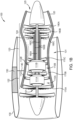
- FIGS 1A and 1B illustrate cross-sectional views of turbine engines 100, (individually, turbine engine 100A and turbine engine 100B) which include one or more electrical generators 110.
- the turbine engines 100 include an enclosure 120 defining an air intake 121 at an upstream end, a compression section 122 downstream of the air intake 121, a combustion section 123 downstream of the compression section 122, a turbine section 124 downstream of the combustion section 123, and an exhaust 125 at a downstream end.
- the enclosure 120 is included inside of a nacelle 130 (also referred to as a housing), and a bypass flow chamber 131 is defined between an outer surface of the enclosure 120 and an inner surface of the nacelle 130.
- a transfer cable 140 linking the electrical generators 110 to a power distribution bus 150 or other power transfer mechanism for a vehicle e.g., a cable connector, spliter, or a protective device such as circuit breaker, or bus tie
- a vehicle e.g., a cable connector, spliter, or a protective device such as circuit breaker, or bus tie
- the turbine engine 100 is disposed in the bypass flow chamber 131 running from the enclosure 120 to electrically connect electrical distributors 112 with a power distribution bus (e.g., for a vehicle).
- the turbine engine 100A of Figure 1A includes a first spool shaft 160A (generally, spool shaft or shaft 160 or collectively, shaft assembly) and a second spool shaft 160B, while the turbine engine 100B of Figure 1B includes a first spool shaft 160A, a second spool shaft 160B, and a third spool shaft 160C.
- Each shaft 160 extends coaxially with the other shafts 160, and rotates during operation at different rates relative to one another due to the ejection of high pressure exhaust rotating the turbines 180A-B (generally, turbine 180), which in turn drive the associated compressors 170A-B or 170A-C (generally, compressor 170) at different rates via the associated spool shafts 160.
- a first spool shaft 160A rotates (due to forces imparted by the first turbine 180A) to drive the rotation of a first compressor 170A at a first rotational speed
- a second spool shaft 160B rotates (due to forces imparted by the second turbine 180B) to drive the rotation of a second compressor 170B at a second rotational speed
- the third turbine 180C rotates a third spool shaft 160C to drive the rotation of a third compressor 170C at a third rotational speed, where the first, second, and third rotational speeds are all different from one another.
- the compressors 170 are disposed in the compression section 122 of the enclosure 120, and may each include several fan blades arranged in one or more rows.
- the turbines 180 are disposed in the turbine section 124 of the enclosure 120, and may each include several fan blades arranged in one or more rows.
- various bearings or low friction surfaces may be located between the shafts 160 to improve rotational characteristics of the shafts 160 (e.g., to reduce friction).
- the first spool shaft 160A is a low-pressure shaft relative to the high-pressure shaft of the second spool shaft 160B. Accordingly, the first compressor 170A is located upstream of the second compressor 170B, and rotates at a lower rotational speed than the second compressor 170B during operation of the turbine engine 100. Similarly, the first turbine 180A is located downstream of the second turbine 180B, and rotates at a lower rotational speed than the second turbine 180B during operation of the turbine engine 100.
- the first spool shaft 160A is a low-pressure shaft
- the second spool shaft 160B is a medium-pressure shaft
- the third spool shaft 160C is a high-pressure shaft relative to one another.
- the first compressor 170A is located upstream of the second compressor 170B, which is located upstream of the third compressor 170C, each of which operates at lower rotational speeds than downstream compressors 170 during operation of the turbine engine 100.
- the first turbine 180A is located downstream of the second turbine 180B, which is located downstream of the third turbine 180C, each of which operates at progressively lower rotational speeds than upstream turbines 180 during operation of the turbine engine 100.
- a first differential rotational speed exists between the first spool shaft 160A and the second spool shaft 160B (and any components attached thereto) during operation
- a second differential rotational speed (which may be the same as or different than the first differential rotational speed) exists between the second spool shaft 160B and the third spool shaft 160C (and any components attached thereto).
- the electrical generators 110 include electrical extractors 111 affixed to the compressors 170 and electrical distributors 112 affixed to the enclosure 120.
- the electrical extractors 111 are not physically connected to the electrical distributors 112, but are separated by an empty space (e.g., an "air gap") and electromagnetically linked during operation by a generated electromagnetic field.
- the electrical extractors 111 are connected to the compressors 170 and capitalize on the different rotational speeds of the compressors 170 attached to different shafts 160 to rotate the components relative to one another using the operational rotation of the components of the turbine engine 100.
- an electrical extractor 111 is located at the interface between the first compressor 170A and the second compressor 170B.
- a first electrical extractor 111A is located at the interface between the first compressor 170A and the second compressor 170B, and a second electrical extractor 111B is located at the interface between the second compressor 170B and the third compressor 170C.
- Each electrical extractor 111 is associated with a corresponding electrical distributor 112 affixed radially around a corresponding portion of the enclosure 120 (e.g., a first electrical extractor 111A corresponding to a first electrical distributor 112A, a second electrical extractor 111B corresponding to a second electrical distributor 112B).
- the electrical distributor 112 includes a resonant receiver for receiving high frequency power from the electrical extractor 111 and a power conversion unit (PCU) to convert the high frequency power to a predefined frequency (e.g., 400 Hz) for consumption and/or storage in the vehicle, and is connected to the power distribution bus 150 via the cable 140.
- a predefined frequency e.g. 400 Hz
- the turbine engine 100 may include only one electrical generator 110; omitting one of the first electrical generator 110A or the second electrical generator 110B. Additionally, although one arrangement of the components of the electrical generators 110 is shown in Figures 1A and 1B , the components may be arranged in various configurations, such as those discussed in relation to Figures 2A-2B and 3A-3B.
- Figures 2A-2D illustrate cross-sectional views of the components of an electrical generator 110.
- Figures 2A and 2B illustrate the components arranged with a radial magnetic linkage
- Figures 2C and 2D illustrate the components arranged with an axial magnetic linkage.
- Figures 2A-2D illustrate one segment of a radially arranged electrical generators 110
- an electrical generator 110 may be constructed as illustrated in one of Figures 2A-2D or more than one of Figures 2A-2D at different arc segments in the radial arrangement around the shafts 160/within the enclosure 120 of the turbine engine 100.
- the electrical extractors 111 are located at the interface of two compressors 170A and 170B.
- the illustrated electrical extractors 111 may be located on the first compressor 170A and the second compressor 170B.
- the illustrated electrical extractors 111 may be located on the second compressor 170B and the third compressor 170C.
- the components illustrated in Figure 2A-2D may belong to a sole electrical extractor 111 (as in Figure 1A ), or to one of a primary or secondary electrical extractor 111 (as in Figure 1B ).
- the individual components may be arranged both according to the same one of Figures 2A-2D or one according to a first one of Figures 2A-2D and the other one according to a different one of Figures 2A-2D .
- the components of one electrical generator 110 may be distinguished by referring to those components as "secondary" components.
- a first electrical extractor 111A includes a primary permanent magnet 220
- a second electrical extractor 111B includes a secondary permanent magnet 220.
- a first electrical extractor 111A is attached to a primary first compressor 170A and a primary second compressor 170B
- a second electrical extractor 111B is attached to a secondary first compressor 170A (which may be a different end of the same compressor 170 as the primary first compressor 170A or the primary second compressor 170B) and a secondary second compressor 170B (which may be a different end of the same shaft 170 as the primary first compressor 170A or the primary second compressor 170B).
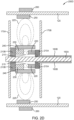
- FIG. 2A illustrates a first component arrangement 200A for an electrical extractor 111, according to aspects of the present disclosure.
- a first rotor assembly 210A (generally, rotor assembly 210) is connected to a lower-pressure first compressor 170A and a second rotor assembly 210B is connected to a higher-pressure second compressor 170B at an interface between the two compressors 170.
- the rotor assemblies 210 are connected to one or more blades of the associated compressor 170, to a ring/connection point of the blades to an associated spool shaft 160, or to the associated spool shaft 160.
- the rotor assemblies 210 position various electromagnetic components of the electrical extractor 111 at known distances and orientations relative to one another, the shafts 160, the compressors 170, and the electrical distributor 112.
- the first rotor assembly 210A includes a permanent magnet 220, which produces a first magnetic field 215.
- the permanent magnet 220 emits the first magnetic field 215 radially through an air gap defined coaxially to the shafts 160 to magnetically link the permanent magnet 220 with an armature winding 230 included in the second rotor assembly 210B.
- the permanent magnet 220 may include a plurality of magnets arranged circumferentially around the shafts 160 to emit a plurality of first magnetic fields 215.
- the second rotor assembly 210B includes the armature winding 230 and a resonant emitter 240.
- the armature winding 230 is arranged concentrically and radially around, but not in physical contact with, the permanent magnet 220 or the shafts 160, and positions the armature winding 230 within a predefined field strength of the first magnetic field 215. Accordingly, the first magnetic field 215 radially links the permanent magnet 220 and the armature winding 230.
- the armature winding 230 when rotated relative to the permanent magnet 220, the armature winding 230 produces a first current ( I 1 ) as a multiphase alternating current, which is input to power the resonant emitter 240 to generate a second magnetic field 225.
- the second rotor assembly 210B positions the resonant emitter 240 outside of a predefined field strength of the first magnetic field 215, and accordingly, the permanent magnet 220 is positioned outside of a predefined field strength of the second magnetic field 225.
- the second magnetic field 225 is radially emitted outward from the resonant emitter 240 to electromagnetically link the resonant emitter 240 with a resonant receiver 250.
- FIG. 2B illustrates a second component arrangement 200B for an electrical extractor 111, according to aspects of the present disclosure.
- a first rotor assembly 210A is connected to a higher-pressure second compressor 170B and a second rotor assembly 210B is connected to a lower-pressure second compressor 170A at an interface between the two compressors 170.
- the rotor assemblies 210 are connected to one or more blades of the associated compressor 170, to a ring/connection point of the blades to an associated spool shaft 160, or to the associated spool shaft 160.
- the rotor assemblies 210 position various electromagnetic components of the electrical extractor 111 at known distances and orientations relative to one another, the shafts 160, the compressors 170, and the electrical distributor 112.
- the first rotor assembly 210A includes a permanent magnet 220, which produces a first magnetic field 215.
- the permanent magnet 220 emits the first magnetic field 215 radially through an air gap defined coaxially to the shafts 160 to magnetically link the permanent magnet 220 with an armature winding 230 included in the second rotor assembly 210B.
- the permanent magnet 220 may include a plurality of magnets arranged circumferentially around the shaft 160 to emit a plurality of first magnetic fields 215.
- the second rotor assembly 210B includes the armature winding 230 and a resonant emitter 240.
- the armature winding 230 is arranged concentrically and radially, but not in physical contact with, the permanent magnet 220 or the shafts 160, and positions the armature winding 230 within a predefined field strength of the first magnetic field 215. Accordingly, the first magnetic field 215 radially links the permanent magnet 220 and the armature winding 230.
- the armature winding 230 when rotated relative to the permanent magnet 220, the armature winding 230 produces a first current ( I 1 ) as a multiphase alternating current, which powers the resonant emitter 240 to generate a second magnetic field 225.
- the second rotor assembly 210B positions the resonant emitter 240 outside of a predefined field strength of the first magnetic field 215, and accordingly, the permanent magnet 220 is positioned outside of a predefined field strength of the second magnetic field 225.
- the second magnetic field 225 radially links the resonant emitter 240 with a resonant receiver 250.
- FIG. 2C illustrates a third component arrangement 200C for an electrical extractor 111, according to aspects of the present disclosure.
- a first rotor assembly 210A is connected to a lower-pressure first compressor 170A and a second rotor assembly 210B is connected to a higher-pressure second compressor 170B at an interface between the two compressors 170.
- the rotor assemblies 210 are connected to one or more blades of the associated compressor 170, to a ring/connection point of the blades to an associated spool shaft 160, or to the associate shaft 160.
- the rotor assemblies 210 position various electromagnetic components of the electrical extractor 111 at known distances and orientations relative to one another, the shafts 160, the compressors 170, and the electrical distributor 112.
- the first rotor assembly 210A includes a permanent magnet 220, which produces a first magnetic field 215.
- the permanent magnet 220 emits the first magnetic field 215 through an air gap defined in a plane intersecting the axis of rotation for the shafts 160 to magnetically link the permanent magnet 220 with an armature winding 230 included in the second rotor assembly 210B.
- the air gap may be defined at other angles relative to the shafts 160.
- the permanent magnet 220 may include a plurality of magnets arranged radially around the shaft 160 to emit a plurality of first magnetic fields 215.
- the second rotor assembly 210B includes the armature winding 230 and a resonant emitter 240.
- the armature winding 230 is arranged radially around, but not in physical contact with, the shafts 160 and arranged planetary to the permanent magnet 220.
- planetary planetary
- the objects rotate about a shared axis of rotation (at the same or different radial distances from the axis of rotation), but at different points along the length of the axis of rotation so as to be clear of the orbit (i.e., not physically contact) of the other object.
- the relative positions and lengths of the rotor assemblies 210 position the armature winding 230 within a predefined field strength of the first magnetic field 215. Accordingly, the first magnetic field 215 axially links the permanent magnet 220 and the armature winding 230.
- the armature winding 230 when rotated relative to the permanent magnet 220, the armature winding 230 produces a first current ( I 1 ) as a multiphase alternating current, which powers the resonant emitter 240 to generate a second magnetic field 225.
- the second rotor assembly 210B positions the resonant emitter 240 outside of a predefined field strength of the first magnetic field 215, and accordingly, the permanent magnet 220 is positioned outside of a predefined field strength of the second magnetic field 225.
- the second magnetic field 225 radially links the resonant emitter 240 with a resonant receiver 250.
- FIG. 2D illustrates a fourth component arrangement 200D for an electrical extractor 111, according to aspects of the present disclosure.
- a first rotor assembly 210A is connected to a higher-pressure first compressor 170A and a second rotor assembly 210B is connected to a lower-pressure second compressor 170B at an interface between the two compressors 170.
- the rotor assemblies 210 are connected to one or more blades of the associated compressor 170, to a ring/connection point of the blades to an associated spool shaft 160, or to the associated spool shaft 160.
- the rotor assemblies 210 position various electromagnetic components of the electrical extractor 111 at known distances and orientations relative to one another, the shafts 160, the compressors 170, and the electrical distributor 112.
- the first rotor assembly 210A includes a permanent magnet 220, which produces a first magnetic field 215.
- the permanent magnet 220 emits the first magnetic field 215 through an air gap defined in a plane intersecting the axis of rotation for the shafts 160 to magnetically link the permanent magnet 220 with an armature winding 230 included in the second rotor assembly 210B.
- the air gap may be defined at other angles relative to the shafts 160.
- the permanent magnet 220 may include a plurality of magnets arranged radially around the shaft 160 to emit a plurality of first magnetic fields 215.
- the second rotor assembly 210B includes the armature winding 230 and a resonant emitter 240.
- the armature winding 230 is arranged radially around, but not in physical contact with, the shafts 160 and arranged planetary to the permanent magnet 220.
- the relative positions and lengths of the rotor assemblies 210 position the armature winding 230 within a predefined field strength of the first magnetic field 215. Accordingly, the first magnetic field 215 axially links the permanent magnet 220 and the armature winding 230.
- the armature winding 230 when rotated relative to the permanent magnet 220, the armature winding 230 produces a first current ( I 1 ) as a multiphase alternating current, which powers the resonant emitter 240 to generate a second magnetic field 225.
- the second rotor assembly 210B positions the resonant emitter 240 outside of a predefined field strength of the first magnetic field 215, and accordingly, the permanent magnet 220 is positioned outside of a predefined field strength of the second magnetic field 225.
- the second magnetic field 225 radially links the resonant emitter 240 with a resonant receiver 250.
- a resonant receiver 250 of an electrical distributor 112 is affixed to an interior surface of the enclosure 120, and is positioned in relation to the resonant emitter 240 to receive at least a predefined field strength of the second magnetic field 225.
- the resonant receiver 250 is arranged with radial symmetry around the enclosure 120, and is configured to receive the second magnetic field 225 to produce a third multiphase alternating current ( I 3 ) that is provided to a power control unit 260 (also referred to as a PCU) that conditions the power for provision to a bus or other electrical distribution system of a vehicle.
- the rotational forces imparted by turbines cause the compressors 170 and attached EM components to rotate relative to one another and the stationary enclosure 120. Due to the differential in the rotational speeds of the higher-pressure compressor 170 and the lower-pressure compressor 170, the first magnetic field 215 rotates relative to the armature winding 230, and the second magnetic field 225 rotates relative to the (nominally stationary) resonant receiver 250. Accordingly, electrical energy is extracted from the rotational forces of the shafts 160 and is wirelessly transferred between the various assemblies via magnetic fields instead of via mechanical transfer components, such as gears or the like.
- a fabricator may alter the relative sizes, shapes, and orientations of these components based on the physical properties of the turbine engine 100 in which the components are installed (e.g., length, thickness, circumference, gap distance, rotational torque, and speed, operating temperature), the desired power characteristics for the extracted power (e.g., number of power phases, voltage/current levels), and the like.
- the lengths of the components along the axis of the shafts 160 are determined by the torque and/or power rating requirements of the vehicle from the turbine engine 100, and the relative sizes and distances of individual components are sized to optimize torque production and speed from the turbine engine 100 and power transfer efficiency in the electrical generator 110 within the physical confines of the turbine engine 100.
- Figures 2A-2D are intended to demonstrate the concepts of operation, and not necessarily a specific implementation, which may be modified based on the power requirements, thrust requirements, turbine engine specific fuel consumption, and material properties of various components.
- a fabricator can design the permanent magnet 220 and the armature winding 230 according to Figures 2A or 2B when radial space along the length of blades of the compressors 170 is more readily available or according to Figures 2C or 2D when axial space between the compressors 170 is more readily available.
- the resonant emitter 240 may be sized and positioned to overlay the armature winding 230 and/or the permanent magnet 220 so that the resonant emitter 240 extends over the entire length of the electrical extractor 111, and the length and position of the resonant receiver 250 is matched to overlay the resonant emitter 240.
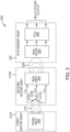
- Figure 3 is a circuit diagram 300 of the EM components of an electrical generator 110.
- the first rotor assembly 210A (which includes the permanent magnet 220) is arranged in magnetic contact, but not physical contact, with the second rotor assembly 210B (which includes the armature winding 230 and the resonant emitter 240) via the first magnetic field 215.
- magnetic contact describes the state in which a magnetic field produced by a permanent or electromagnet is of at least a predefined strength between two components.
- the armature winding 230 includes a plurality of receiving windings 310A-C (generally, receiving winding 310) that each produce one phase of power from the received first magnetic field 215.
- receiving windings 310A-C generally, receiving winding 310 that each produce one phase of power from the received first magnetic field 215.
- the first rotor assembly 210A is connected to one compressor 170 of the turbine engine 100, such as shown in Figures 2A-2D and the second rotor assembly 210B is connected to a second compressor 170 of the turbine engine 100, such as shown in Figures 2A-2D . Due to the difference in rotational speeds of each compressor 170 when the turbine engine 100 is in operation, the first rotor assembly 210A rotates at the differential speed relative to the second rotor assembly 210B.
- the second rotor assembly 210B is arranged in magnetic contact, but not physical contact, with a stationary assembly 320 via the resonant emitter 240 and the resonant receiver 250.
- the stationary assembly 320 is disposed on (or through) the enclosure 120 of the turbine engine 100, and as such, remains stationary relative to the rotating compressors 170 and the EM components connected thereto.
- the stationary assembly 320 includes the resonant receiver 250 and the power control unit 260, which physically connects the stationary assembly 320 to an electrical bus or other power distribution system for the vehicle.
- the resonant emitter 240 and resonant receiver 250 which are discussed in greater detail in regard to Figure 5 , respectively generate and receive the second magnetic field 225 as a high-frequency magnetic field at a predefined resonant frequency to produce a power output to the power control unit 260 and the vehicle.
- FIG. 4 is a circuit diagram 400 detailing a three-phase example of the resonant emitter 240 and resonant receiver 250, according to aspects of the present disclosure.
- the armature winding 230 includes a plurality of receiving windings 310A-C that each produce one phase of power (e.g., I 1 ⁇ 1 , I 1 ⁇ 2 , I 1 ⁇ 3 ) due to the interaction of the armature windings with the received first magnetic field 215.
- a different corresponding number of receiving windings 310 are used.
- the power is carried from the receiving windings 310 to a high frequency three-phase converter 410, such as, for example, one or more insulated-gate bipolar transistors (IGBT), Metal oxide semiconductor field effect transistors (MOSFET), or other controlled switching devices, to increase the frequency of the power to generate the second magnetic field 225 at a predefined frequency.
- a high frequency three-phase converter 410 such as, for example, one or more insulated-gate bipolar transistors (IGBT), Metal oxide semiconductor field effect transistors (MOSFET), or other controlled switching devices, to increase the frequency of the power to generate the second magnetic field 225 at a predefined frequency.
- the predefined frequency is greater than the difference between the rotational speeds of the compressors 170 to which the resonant emitter 240 and other components of the electrical extractor 111 are connected, and is tuned for power transfer efficiency over the air gap between the resonant emitter 240 and the resonant receiver 250.
- Emitter capacitors 420A-C are disposed on each output from the high frequency converter 410, each of which is connected in series with a phase inductor 430A-C (generally, phase winding 430) to form a LC resonant circuit to generate the second magnetic field 225 at a pre-determined resonant frequency.
- Each phase winding 430 receives one phase of high frequency power, and generates one phase of the second magnetic field 225.
- a second current e.g., I 2 ⁇ 1 , I 2 ⁇ 2 , I 2 ⁇ 3
- Each receiver resonant circuit, inductor or winding 440 and capacitor 450, is connected to the power control unit 260.
- the power control unit 260 may convert the power from AC to DC (or AC to AC), increase or reduce the number of phases of the power, make or break an electrical connection to the bus, raise or lower a voltage of the power, raise or lower the frequency of the power, and the like to condition the power for consumption or storage by the vehicle.
- circuitry of the resonant emitter 240 and resonant receiver 250 may include RLC (Resistive, Inductive, and Capacitive) elements in other arrangements that allow for a resonant magnetic linkage between the resonant emitter 240 and the resonant receiver 250 when the resonant emitter 240 is powered.
- RLC Resistive, Inductive, and Capacitive
- Other examples include parallel LC circuits, RLC circuits, actively tuned resonant circuits, etc.
- Figure 5 is a flowchart of a method 500 of construction for an electrical generator 110, according to aspects of the present disclosure.
- Method 500 may be performed during initial assembly of a turbine engine 100, during retrofit or repair of a turbine engine 100, or as a pre-assembly operation for components of a turbine engine 100.
- Method 500 begins with block 510, where a fabricator affixes a permanent magnet 220 to a first compressor shaft.
- the first compressor shaft may be shaft 160 associated with the lower-pressure compressor 170 or the higher-pressure compressor 170 at an interface region between two compressors 170, and the permanent magnet 220 is affixed directly or via a first rotor assembly 210A.
- block 510 may be repeated to allow a fabricator to affix a secondary permanent magnet 220 to a secondary first compressor shaft (e.g., at a different location on a shaft 160 within the primary electrical generator 110) for use in a secondary electrical generator 110 in a three-shaft turbine engine 100.
- a fabricator affixes a second rotor assembly 210B, including an armature-emitter assembly, to the second compressor shaft.
- the fabricator affixes the second rotor assembly 210B to a shaft 160 associated with a lower-pressure compressor 170 when the permanent magnet 220 is affixed to the shaft 160 of the higher-pressure compressor 170, but affixes the second rotor assembly 210B to a shaft 160 associated with a higher-pressure compressor 170 when the permanent magnet 220 is affixed to the shaft 160 associated with the lower-pressure compressor 170.
- the interface region between the first and second compressors 170 defines an area that is free of fans or blades of the corresponding compressors 170.
- block 520 may be repeated to allow a fabricator to affix a secondary second rotor assembly 210B to a secondary second compressor shaft (e.g., shaft 160 associated with a third compressor 170C) for use in a secondary electrical generator 110 in a three-shaft turbine engine 100.
- a secondary second compressor shaft e.g., shaft 160 associated with a third compressor 170C
- the second rotor assembly 210B includes the armature winding 230, and the resonant emitter 240, and spacers.
- the spacers arrange the armature winding 230 and the resonant emitter 240 to position the armature winding 230 in the first magnetic field 215 and to separate the first magnetic field 215 from the second magnetic field 225 when the compressors 170 rotate relative to one another during operation of the turbine engine 100.
- the spacers also position the resonant emitter 240 at a set location to interface and magnetically couple with the resonant receiver 250 when the turbine engine 100 is operational.
- a fabricator affixes a resonant receiver 250 to an interior surface of the enclosure 120 for the turbine engine 100 in relation to the interface region between the two compressors 170 and where the second magnetic field 225 is produced during operation of the turbine engine 100.
- block 530 may be repeated to allow a fabricator to affix a secondary resonant receiver 250 to a secondary location on the interior surface of the enclosure 120, corresponding to the interface region between the two compressors 170 used by the secondary electrical generator 110 and where the secondary second magnetic field 225 is produced during operation of the turbine engine 100.
- Method 500 may then conclude.
- Figure 6 is a flowchart of a method 600 for wirelessly extracting electrical energy from a turbine engine 100, according to aspects of the present disclosure.
- method 600 may be performed twice in parallel - extracting electrical power from the differential rotation of a primary electrical generator 110 and a secondary electrical generator 110 located on the interfaces between different pairs of compressors 170.
- Method 600 begins at block 610, where an operator of the turbine engine 100 causes the permanent magnet 220 attached to a first compressor 170A of a turbine engine 100 to rotate relative to a second compressor 170B of the turbine engine 100.
- the operator may cause the relative rotation by engaging the turbine engine 100 to produce thrust for a vehicle; inducing rotational energy on the compressors 170 by the combustion of fuel in a combustion chamber and expelling the exhaust through a turbine region, thus causing the turbines 180 to rotate the corresponding shafts 160 and thereby rotate the compressors 170.
- the permanent magnet 220 which may be part of an array of permanent magnets 220 connected to a first compressor 170A and arranged radially around the shafts 160, emits a first magnetic field 215.
- the first magnetic field 215 When rotated, the first magnetic field 215 induces a first current, as a multiphase alternating current (e.g., I 1 ⁇ 1-3 ), in an armature winding 230 that is connected to a second compressor 170B and also arranged radially around the shafts 160.
- a multiphase alternating current e.g., I 1 ⁇ 1-3
- the armature winding 230 is arranged coaxially with the permanent magnets 220, planetarily with the permanent magnets 220, or alternatingly coaxially and planetarily with the permanent magnet 220 around the shaft 160.
- the air gap between the permanent magnet 220 and the armature winding 230 through with the first magnetic field 215 propagates may be coaxial to the shafts 160, defined in a plane that intersects the shafts 160, or vary between coaxial or intersecting planes at different locations around the shaft 160.
- the "first" compressor 170A may refer to a first one of a high-pressure compressor or a low-pressure compressor in a two-shaft turbine engine 100, and the “second” compressor 170B may refer to the other compressor.
- the "first” compressor 170A may refer to a high-pressure compressor or a low-pressure compressor, in which case the “second” compressor 170B refers to a medium-pressure compressor, or the "first" shaft 170A may refer to the medium-pressure compressor, in which case the "second” shaft 170B may refer to either the high-pressure compressor or the low-pressure compressor.
- the designations of "high-,” “medium-,” and “low-” pressures are used to refer to different components within the turbine engine 100 based on the relative operational pressures between those components. Accordingly, in a given pair of rotors, one shall be understood to be the higher-pressure rotor and the other to be the lower-pressure rotor.
- the first current ( I 1 ) powers an electromagnet (e.g., a resonant emitter 240) to generate a second magnetic field 225 at or above a predefined frequency.
- the predefined frequency is tuned to the characteristics of the turbine engine 100, including, but not limited to, the distance between the resonant emitter 240 and the resonant receiver 250, the relative location in space of the second magnetic field 225 to the first magnetic field 215 in the electrical generator 110, the relative location of a primary electrical generator 110 to a secondary electrical generator 110, the rotational speeds of the compressors 170, etc.
- the predefined frequency is set high (e.g., at least 10 kHz) to thereby reduce losses when wirelessly transferring power via the resonant emitter 240 to the resonant receiver 250.
- a resonant receiver 250 which is disposed on an inner surface of the enclosure 120, converts the radiated electromagnetic field power (e.g., from the rotating second magnetic field 225) into an electrical power output.
- the electrical power output is a fourth current ( I 4 ) that is provided as a multiphase alternating current (AC) electrical power output, but in other aspects, the electrical output may be single phase and/or direct current (DC), depending on the power consumption characteristics of the vehicle.
- the resonant receiver 250 transfers the power to an electrical bus for use and/or storage by the vehicle.
- the resonant receiver 250 transfers the power output to the bus via a power control unit 260, which may condition the power, convert the power from AC to DC (or DC to AC), reduce or increase the number of phases of the power, make or break an electrical connection to the bus, raise or lower a voltage of the power, raise or lower the frequency of the power, and the like.
- Method 600 may continue as long the first and second compressors 170 rotate relative to each other.
- aspects described herein may be embodied as a system, method or computer program product. Accordingly, aspects may take the form of an entirely hardware aspect, an entirely software aspect (including firmware, resident software, microcode, etc.) or an aspect combining software and hardware aspects that may all generally be referred to herein as a "circuit,” “module” or “system.” Furthermore, aspects described herein may take the form of a computer program product embodied in one or more computer readable storage medium(s) having computer readable program code embodied thereon.
- These computer program instructions may also be stored in a computer readable medium that can direct a computer, other programmable data processing apparatus, or other device to function in a particular manner, such that the instructions stored in the computer readable medium produce an article of manufacture including instructions which implement the function/act specified in the block(s) of the flowchart illustrations and/or block diagrams.
- the computer program instructions may also be loaded onto a computer, other programmable data processing apparatus, or other device to cause a series of operational steps to be performed on the computer, other programmable apparatus or other device to produce a computer implemented process such that the instructions which execute on the computer, other programmable data processing apparatus, or other device provide processes for implementing the functions/acts specified in the block(s) of the flowchart illustrations and/or block diagrams.
- each block in the flowchart illustrations or block diagrams may represent a module, segment, or portion of code, which comprises one or more executable instructions for implementing the specified logical function(s).
- the functions noted in the block may occur out of the order noted in the Figures. For example, two blocks shown in succession may, in fact, be executed substantially concurrently, or the blocks may sometimes be executed in the reverse order or out of order, depending upon the functionality involved.
Landscapes
- Engineering & Computer Science (AREA)
- Power Engineering (AREA)
- Chemical & Material Sciences (AREA)
- Combustion & Propulsion (AREA)
- Aviation & Aerospace Engineering (AREA)
- Mechanical Engineering (AREA)
- General Engineering & Computer Science (AREA)
- Microelectronics & Electronic Packaging (AREA)
- Computer Networks & Wireless Communication (AREA)
- Connection Of Motors, Electrical Generators, Mechanical Devices, And The Like (AREA)
- Structures Of Non-Positive Displacement Pumps (AREA)
- Turbine Rotor Nozzle Sealing (AREA)
- Control Of Eletrric Generators (AREA)
- Permanent Magnet Type Synchronous Machine (AREA)
Claims (15)
- Système comprenant :un premier ensemble rotor (210A) comportant un aimant permanent (220) qui émet un premier champ magnétique (215) et qui est adapté pour être connecté à un premier compresseur d'un moteur à turbine (100) ;un second ensemble rotor (210B) comportant un enroulement d'induit (230) etun émetteur résonant (240), dans lequel le second ensemble rotor (210B) est adapté pour être connecté à un deuxième compresseur du moteur à turbine au niveau d'une interface entre le premier compresseur et le deuxième compresseur, de telle sorte que l'enroulement d'induit est positionné à l'intérieur du premier champ magnétique, et l'émetteur résonant est configuré pour recevoir une entrée d'alimentation électrique à partir de l'enroulement d'induit afin de générer un second champ magnétique (225) d'au moins une fréquence prédéfinie lorsque le premier ensemble rotor tourne par rapport au second ensemble rotor ; etun récepteur résonant (250), configuré pour être disposé sur une enceinte (120) du moteur à turbine, positionné par rapport à l'émetteur résonant pour recevoir le second champ magnétique et convertir le second champ magnétique en une alimentation électrique de sortie.
- Système selon la revendication 1, dans lequel :le premier ensemble rotor est adapté pour être connecté à un compresseur à plus haute pression,le second ensemble rotor est adapté pour être connecté à un compresseur à plus basse pression, etle premier ensemble rotor est configuré pour tourner à une première vitesse qui est supérieure à une seconde vitesse à laquelle le second ensemble rotor est configuré pour tourner.
- Système selon la revendication 1, dans lequel :le premier ensemble rotor est adapté pour être connecté à un compresseur à plus basse pression,le second ensemble rotor est adapté pour être connecté à un compresseur à plus haute pression, etle premier ensemble rotor est configuré pour tourner à une première vitesse supérieure à une seconde vitesse à laquelle le second ensemble rotor est configuré pour tourner.
- Système selon l'une quelconque des revendications 1 à 3, dans lequel, une fois le système connecté à un moteur à turbine, le premier champ magnétique se propage radialement vers l'extérieur à partir d'un axe de rotation pour le premier ensemble rotor sur un entrefer défini entre l'aimant permanent et l'enroulement d'induit.
- Système selon l'une quelconque des revendications 1 à 4, dans lequel, une fois le système connecté à un moteur à turbine, le premier champ magnétique se propage coaxialement à un axe de rotation pour le premier ensemble rotor sur un entrefer défini entre l'aimant permanent et l'enroulement d'induit.
- Système selon l'une quelconque des revendications 1 à 5, comprenant en outre :un convertisseur haute fréquence disposé entre l'enroulement d'induit et l'émetteur résonant ; etdans lequel le convertisseur haute fréquence est configuré pour fournir à l'émetteur résonant l'entrée d'alimentation électrique à une fréquence supérieure à celle que le premier champ magnétique est reçu par l'enroulement d'induit, etdans lequel la fréquence supérieure est supérieure à une différence de vitesse de rotation entre le premier ensemble rotor et le second ensemble rotor et est basée sur une efficacité du transfert de puissance entre l'émetteur résonnant et le récepteur résonnant.
- Système selon l'une quelconque des revendications 1 à 6, dans lequel l'alimentation électrique de sortie comporte une pluralité de phases électriques basées sur un nombre de phases défini dans l'enroulement d'induit.
- Système selon l'une quelconque des revendications 1 à 7, comprenant en outre une unité de commande d'alimentation (260) configurée pour être disposée dans l'enceinte et pour être connectée à un bus de distribution d'alimentation (150) pour un véhicule.
- Moteur à turbine (100), comprenant :
une enceinte (120), comprenant :une entrée d'air (121) au niveau d'une extrémité amont ;une section de compression (122) en aval de l'entrée d'air ;une section de combustion (123) en aval de la section de compression ;une section de turbine en aval (124) de la section de combustion ; etun échappement (125) au niveau d'une extrémité aval ;un premier compresseur et un deuxième compresseur disposés dans la section de compression (122) de l'enceinte (120) ;une première turbine et une deuxième turbine disposées dans la section de turbine (124) de l'enceinte (120) ;un premier arbre (160) accouplé au premier compresseur (170) et à la première turbine (180), dans lequel le premier arbre est configuré pour tourner à une première vitesse de rotation ;un deuxième arbre (160) accouplé au deuxième compresseur (170) et à la deuxième turbine (180) et fonctionnant coaxialement avec le premier arbre, dans lequel le deuxième arbre est configuré pour tourner à une deuxième vitesse de rotation ;un système selon l'une quelconque des revendications précédentes, dans lequel le second ensemble rotor (210B) est connecté à un premier parmi le premier compresseur et le deuxième compresseur ;le premier ensemble rotor (210A) est connecté à l'autre parmi le premier et le deuxième compresseur, de telle sorte que l'aimant permanent (220) est configuré pour :émettre un premier champ magnétique (215) ;tourner par rapport à l'enroulement d'induit (230) à une vitesse de rotation différentielle correspondant à une différence entre la première vitesse de rotation et la deuxième vitesse de rotation ; etinduire un courant dans l'enroulement d'induit ;et que l'émetteur résonant (240) est configuré pour générer un second champ magnétique (225) d'au moins une fréquence prédéfinie lorsqu'il est alimenté par le courant ;dans lequel le récepteur résonant (250) est disposé sur l'enceinte du moteur à turbine, positionné pour recevoir le second champ magnétique, et configuré pour convertir le second champ magnétique en une alimentation électrique de sortie. - Moteur à turbine selon la revendication 9, comprenant en outre :un troisième compresseur disposé dans la section de compresseur, en aval du premier compresseur et du deuxième compresseur ;une troisième turbine disposée dans la section de turbine en amont de la première turbine et de la deuxième turbine ;un troisième arbre (160) accouplé au troisième compresseur (170) et à la troisième turbine (180),dans lequel le troisième arbre s'étend coaxialement au deuxième arbre et est configuré pour tourner à une troisième vitesse de rotation qui est supérieure à la première vitesse de rotation et à la deuxième vitesse de rotation, le moteur à turbine comprenant en outre :un enroulement d'induit secondaire (230), connecté à l'un parmi le troisième compresseur et le deuxième compresseur ;un aimant permanent secondaire (220), connecté à un deuxième parmi le troisième compresseur et le deuxième compresseur, et configuré pour :émettre un premier champ magnétique secondaire (215) ;tourner par rapport à l'enroulement d'induit secondaire à une vitesse de rotation différentielle secondaire correspondant à une différence secondaire entre la troisième vitesse de rotation et la deuxième vitesse de rotation ; etinduire un courant secondaire dans l'enroulement d'induit secondaire ;un émetteur résonant secondaire (240) connecté à l'enroulement d'induit secondaire et configuré pour générer un second champ magnétique secondaire (225) d'au moins une fréquence prédéfinie secondaire lorsqu'il est alimenté par le courant secondaire ; etun récepteur résonnant secondaire (250) disposé sur l'enceinte du moteur à turbine, positionné pour recevoir le second champ magnétique secondaire, et configuré pour convertir le second champ magnétique secondaire en une alimentation électrique secondaire de sortie.
- Moteur à turbine selon la revendication 9, comprenant en outre :un troisième compresseur disposé dans la section de compression en amont du compresseur et du deuxième compresseur ;une troisième turbine disposée dans la section de turbine en aval de la première turbine et de la deuxième turbine ;un troisième arbre (160) accouplé au troisième compresseur (170) et à la troisième turbine (180) ; etdans lequel le troisième arbre s'étend coaxialement au deuxième arbre et est configuré pour tourner à une troisième vitesse de rotation qui est inférieure à la première vitesse de rotation et à la deuxième vitesse de rotation, le moteur à turbine comprenant en outre :un enroulement d'induit secondaire (230), connecté à un premier compresseur parmi le troisième compresseur et le premier compresseur ;un aimant permanent secondaire (220), connecté à un deuxième compresseur parmi le troisième compresseur et le premier compresseur, et configuré pour :émettre un premier champ magnétique secondaire (215) ;tourner par rapport à l'enroulement d'induit secondaire à une vitesse de rotation différentielle secondaire correspondant à une différence secondaire entre la troisième vitesse de rotation et la première vitesse de rotation ; etinduire un courant secondaire dans l'enroulement d'induit secondaire ;un émetteur résonant secondaire (240) connecté à l'enroulement d'induit secondaire et configuré pour générer un second champ magnétique secondaire (225) d'au moins une fréquence prédéfinie secondaire lorsqu'il est alimenté par le courant secondaire ; etun récepteur résonnant secondaire (250) disposé sur l'enceinte du moteur à turbine, positionné pour recevoir le second champ magnétique secondaire, et configuré pour convertir le second champ magnétique secondaire en une alimentation électrique secondaire de sortie.
- Moteur à turbine selon l'une quelconque des revendications 9 à 11, comprenant en outre :une nacelle (130), définissant une chambre d'écoulement de dérivation (131) dans laquelle l'enceinte est disposée ; etun câble de transfert (140), disposé dans la chambre d'écoulement de dérivation et partant de l'enceinte pour connecter électriquement le récepteur résonant à un bus de distribution d'alimentation (150) pour un véhicule,le moteur à turbine comprend en outre : une unité de commande d'alimentation (260) disposée à l'intérieur de la chambre d'écoulement de dérivation, à l'extérieur de l'enceinte, et connectée électriquement entre le récepteur résonnant et le câble de transfert.
- Moteur à turbine selon l'une quelconque des revendications 9 à 12, dans lequel l'enroulement d'induit et l'aimant permanent sont séparés par un entrefer défini coaxialement au premier arbre.
- Moteur à turbine selon l'une quelconque des revendications 9 à 13, dans lequel l'enroulement d'induit et l'aimant permanent sont séparés par un entrefer défini dans un plan coupant un axe de rotation du premier arbre.
- Procédé (600), comprenant :la rotation (610) d'un premier ensemble rotor (210A) comportant un aimant permanent (220) émettant un premier champ magnétique (215) et connecté à un premier compresseur d'un moteur à turbine (100), autour d'un premier arbre (160) du moteur à turbine pour induire un courant alternatif multiphasé dans un enroulement d'induit (230) inclus dans un second ensemble rotor (210B) connecté à un deuxième compresseur (170) du moteur à turbine, connecté à un deuxième arbre (160) coaxial avec le premier arbre ;l'alimentation (620), par l'intermédiaire du courant alternatif multiphasé, d'un émetteur résonant (240) inclus dans le second ensemble rotor pour générer un second champ magnétique (225) égal ou supérieur à une fréquence prédéfinie ; etla conversion (630) du second champ magnétique en une alimentation électrique de sortie par l'intermédiaire d'un récepteur résonant (250) disposé sur une surface intérieure d'une enceinte (120) du moteur à turbine.
Applications Claiming Priority (1)
| Application Number | Priority Date | Filing Date | Title |
|---|---|---|---|
| US16/744,305 US11362567B2 (en) | 2020-01-16 | 2020-01-16 | Electrical power generation from turbine engines |
Publications (2)
| Publication Number | Publication Date |
|---|---|
| EP3852251A1 EP3852251A1 (fr) | 2021-07-21 |
| EP3852251B1 true EP3852251B1 (fr) | 2024-10-09 |
Family
ID=74003779
Family Applications (1)
| Application Number | Title | Priority Date | Filing Date |
|---|---|---|---|
| EP20217669.9A Active EP3852251B1 (fr) | 2020-01-16 | 2020-12-29 | Génération d'énergie électrique à partir de moteurs à turbine |
Country Status (6)
| Country | Link |
|---|---|
| US (1) | US11362567B2 (fr) |
| EP (1) | EP3852251B1 (fr) |
| JP (1) | JP7665341B2 (fr) |
| CN (1) | CN113206575B (fr) |
| AU (1) | AU2020281179B2 (fr) |
| CA (1) | CA3100622C (fr) |
Families Citing this family (3)
| Publication number | Priority date | Publication date | Assignee | Title |
|---|---|---|---|---|
| KR20220082733A (ko) * | 2020-12-10 | 2022-06-17 | 더 보잉 컴파니 | 다이렉트 드라이브 전기적-기어식 터보팬 |
| US11920510B2 (en) * | 2021-09-10 | 2024-03-05 | Hamilton Sundstrand Corporation | Interstage electric alternator for micro-turbine alternator applications |
| US20250283435A1 (en) * | 2024-03-06 | 2025-09-11 | General Electric Company | Power transfer system for a gas turbine engine |
Family Cites Families (42)
| Publication number | Priority date | Publication date | Assignee | Title |
|---|---|---|---|---|
| US3671850A (en) * | 1970-11-19 | 1972-06-20 | Walter E Mehnert | Electric generator control system with radio feedback loop |
| US3768002A (en) * | 1971-10-01 | 1973-10-23 | Gen Electric | Generator excitation system with rotating electromagnetic energy connector and internal winding power source |
| US4093869A (en) * | 1976-04-13 | 1978-06-06 | Westinghouse Electric Corp. | Quadrature axis field brushless exciter |
| US4641066A (en) * | 1984-10-04 | 1987-02-03 | Nippondenso Co., Ltd. | Control apparatus for brushless motor |
| US4723106A (en) * | 1986-08-29 | 1988-02-02 | General Electric Company | Brushless generator exciter using hybrid rectifier |
| US4982123A (en) * | 1989-11-17 | 1991-01-01 | Sunstrand Corporation | Integrated exciter generator and rotating transformer |
| US5097195A (en) * | 1989-11-27 | 1992-03-17 | Sundstrand Corporation | AC exciter for VSCF starter/generator |
| US5581168A (en) * | 1993-05-12 | 1996-12-03 | Sundstrand Corporation | Starter/generator system with DC link current control |
| US5594322A (en) * | 1993-05-12 | 1997-01-14 | Sundstrand Corporation | Starter/generator system with variable-frequency exciter control |
| FR2712250B1 (fr) | 1993-11-10 | 1995-12-29 | Hispano Suiza Sa | Procédé et dispositif de commande de variation du pas des pales d'un rotor. |
| DE10017548B4 (de) * | 2000-04-08 | 2016-12-01 | Renk Aktiengesellschaft | Generatorgetriebe |
| JP2004515193A (ja) | 2000-11-27 | 2004-05-20 | フランク・ジェイ・フェセラ | 永久磁石モータ |
| JP3901578B2 (ja) * | 2002-05-16 | 2007-04-04 | 本田技研工業株式会社 | 発電装置 |
| US6906479B2 (en) * | 2002-08-06 | 2005-06-14 | Honeywell International, Inc. | Gas turbine engine starter generator with multiple windings on each exciter stator pole |
| US6847194B2 (en) * | 2002-09-20 | 2005-01-25 | Honeywell International Inc. | Electric start for a prime mover |
| US6933704B2 (en) * | 2002-10-11 | 2005-08-23 | Siemens Westinghouse Power Corporation | Slip-inducing rotation starting exciter for turbine generator |
| US6998726B2 (en) * | 2002-12-10 | 2006-02-14 | Honeywell International Inc. | Method and system for providing single-phase excitation techniques to a start exciter in a starter/generator system |
| US7513120B2 (en) | 2005-04-08 | 2009-04-07 | United Technologies Corporation | Electrically coupled supercharger for a gas turbine engine |
| US7508086B2 (en) * | 2006-03-24 | 2009-03-24 | General Electric Company | Aircraft engine starter/generator and controller |
| US7880355B2 (en) | 2006-12-06 | 2011-02-01 | General Electric Company | Electromagnetic variable transmission |
| US7514806B2 (en) * | 2007-06-05 | 2009-04-07 | Honeywell International Inc. | Engine start system with quadrature AC excitation |
| JP2009185782A (ja) | 2008-02-08 | 2009-08-20 | Honda Motor Co Ltd | 発電装置 |
| GB0809247D0 (en) | 2008-05-22 | 2008-06-25 | Rolls Royce Plc | An electrical generator arrangement |
| US8299762B2 (en) * | 2009-06-05 | 2012-10-30 | Hamilton Sundstrand Corporation | Starting/generating system with multi-functional circuit breaker |
| US8773080B2 (en) * | 2010-12-16 | 2014-07-08 | Kohler Co. | Resonant commutation system for exciting a three-phase alternator |
| GB201107833D0 (en) | 2011-05-11 | 2011-06-22 | Rolls Royce Plc | Variable speed generator |
| GB201207754D0 (en) | 2012-05-03 | 2012-06-13 | Rolls Royce Plc | Electro-magnetic coupling system |
| FR2990809B1 (fr) | 2012-05-21 | 2017-04-14 | Hispano-Suiza | Systeme d'alimentation en energie electrique comprenant une machine asynchrone et moteur de propulsion equipe d'un tel systeme d'alimentation en energie electrique |
| CN104704717B (zh) * | 2012-10-01 | 2017-10-24 | 三菱电机株式会社 | 电动驱动装置 |
| US9325229B2 (en) * | 2013-03-15 | 2016-04-26 | Hamilton Sundstrand Corporation | Generator architecture with PMG exciter and main field rotating power converter |
| US9543876B2 (en) * | 2013-06-20 | 2017-01-10 | Hamilton Sundstrand Corporation | Three phase flux switching generator in a three stage wound field synchronous machine |
| US9209741B2 (en) * | 2014-02-24 | 2015-12-08 | The Boeing Company | Method and system for controlling synchronous machine as generator/starter |
| WO2015133301A1 (fr) * | 2014-03-07 | 2015-09-11 | 国立大学法人 東京大学 | Système de moteur-roue |
| US9973058B2 (en) * | 2014-07-23 | 2018-05-15 | Hamilton Sundstrand Corporation | Propeller in-hub power generation and control |
| US10252810B2 (en) | 2016-04-19 | 2019-04-09 | General Electric Company | Propulsion engine for an aircraft |
| DE112017002491T5 (de) | 2016-05-16 | 2019-02-28 | Mitsubishi Heavy Industries, Ltd. | Drahtlose energieversorgungsvorrichtung, telemetrisches messsystem, rotationsmaschine, system zur drahtlosen energieversorgung eines rotierenden körpers, und turbinensystem |
| US11230385B2 (en) | 2017-06-08 | 2022-01-25 | General Electric Company | Hybrid-electric propulsion system for an aircraft |
| GB2568093A (en) | 2017-11-06 | 2019-05-08 | Rolls Royce Plc | Multi-shaft gas turbine engine |
| US10644630B2 (en) * | 2017-11-28 | 2020-05-05 | General Electric Company | Turbomachine with an electric machine assembly and method for operation |
| US11168617B2 (en) | 2019-01-30 | 2021-11-09 | Raytheon Technologies Corporation | Electric enhanced transmission for multi-spool load-sharing turbofan engine |
| US20200309027A1 (en) | 2019-03-27 | 2020-10-01 | Rolls-Royce Deutschland Ltd & Co Kg | Gas turbine engine with an electromagnetic transmission |
| US10934880B1 (en) | 2019-09-04 | 2021-03-02 | The Boeing Company | Electrical generation from turbine engines |
-
2020
- 2020-01-16 US US16/744,305 patent/US11362567B2/en active Active
- 2020-11-25 CA CA3100622A patent/CA3100622C/fr active Active
- 2020-12-07 AU AU2020281179A patent/AU2020281179B2/en active Active
- 2020-12-29 EP EP20217669.9A patent/EP3852251B1/fr active Active
- 2020-12-30 CN CN202011616941.XA patent/CN113206575B/zh active Active
-
2021
- 2021-01-06 JP JP2021000834A patent/JP7665341B2/ja active Active
Also Published As
| Publication number | Publication date |
|---|---|
| CA3100622A1 (fr) | 2021-07-16 |
| CN113206575A (zh) | 2021-08-03 |
| JP7665341B2 (ja) | 2025-04-21 |
| AU2020281179A1 (en) | 2021-08-05 |
| US11362567B2 (en) | 2022-06-14 |
| CA3100622C (fr) | 2025-09-23 |
| CN113206575B (zh) | 2025-06-06 |
| US20210226509A1 (en) | 2021-07-22 |
| EP3852251A1 (fr) | 2021-07-21 |
| AU2020281179B2 (en) | 2025-08-14 |
| JP2021152362A (ja) | 2021-09-30 |
Similar Documents
| Publication | Publication Date | Title |
|---|---|---|
| CA3081087C (fr) | Production electrique de moteurs a turbine | |
| EP3852251B1 (fr) | Génération d'énergie électrique à partir de moteurs à turbine | |
| JP5512111B2 (ja) | ファン内に発電機を配置したターボジェット | |
| EP2654185B1 (fr) | Générateur à rotors multiples | |
| EP2381080A2 (fr) | Boîte de vitesse accessoires avec démarreur/générateur | |
| EP3035504A2 (fr) | Machines électriques | |
| CN102996251A (zh) | 用于从燃气涡轮发动机抽取电功率的方法和装置 | |
| CN111197535A (zh) | 发动机组件 | |
| EP3306793B1 (fr) | Générateur électrique à bobines multiples dans un moteur à turbine | |
| WO2021183170A1 (fr) | Manchon de rotor à agencement de phase magnétique double | |
| EP3023331B1 (fr) | Moteur d'aéronef et procédé de génération d'énergie électrique pour un système d'alimentation d'avion | |
| US11643973B2 (en) | Electrically geared turbofan | |
| CN108468602A (zh) | 一种多轴系分布式可变布雷顿循环航空发动机 | |
| Gieras | High speed machines | |
| EP3812281B1 (fr) | Unité de puissance auxiliaire d'aéronef | |
| BR102020010201B1 (pt) | Sistema, motor de turbina, e método | |
| EP3156630A1 (fr) | Systèmes et procédés destinés à faciliter l'amélioration de la puissance utile de turbine au moyen d'un générateur auxiliaire | |
| CN121794452A (zh) | 包括具有径向布置的固定绕组、励磁绕组和旋转绕组的电机的涡轮机 |
Legal Events
| Date | Code | Title | Description |
|---|---|---|---|
| PUAI | Public reference made under article 153(3) epc to a published international application that has entered the european phase |
Free format text: ORIGINAL CODE: 0009012 |
|
| STAA | Information on the status of an ep patent application or granted ep patent |
Free format text: STATUS: THE APPLICATION HAS BEEN PUBLISHED |
|
| AK | Designated contracting states |
Kind code of ref document: A1 Designated state(s): AL AT BE BG CH CY CZ DE DK EE ES FI FR GB GR HR HU IE IS IT LI LT LU LV MC MK MT NL NO PL PT RO RS SE SI SK SM TR |
|
| STAA | Information on the status of an ep patent application or granted ep patent |
Free format text: STATUS: REQUEST FOR EXAMINATION WAS MADE |
|
| 17P | Request for examination filed |
Effective date: 20220120 |
|
| RBV | Designated contracting states (corrected) |
Designated state(s): AL AT BE BG CH CY CZ DE DK EE ES FI FR GB GR HR HU IE IS IT LI LT LU LV MC MK MT NL NO PL PT RO RS SE SI SK SM TR |
|
| RAP3 | Party data changed (applicant data changed or rights of an application transferred) |
Owner name: THE BOEING COMPANY |
|
| GRAP | Despatch of communication of intention to grant a patent |
Free format text: ORIGINAL CODE: EPIDOSNIGR1 |
|
| STAA | Information on the status of an ep patent application or granted ep patent |
Free format text: STATUS: GRANT OF PATENT IS INTENDED |
|
| INTG | Intention to grant announced |
Effective date: 20231212 |
|
| GRAJ | Information related to disapproval of communication of intention to grant by the applicant or resumption of examination proceedings by the epo deleted |
Free format text: ORIGINAL CODE: EPIDOSDIGR1 |
|
| STAA | Information on the status of an ep patent application or granted ep patent |
Free format text: STATUS: REQUEST FOR EXAMINATION WAS MADE |
|
| INTC | Intention to grant announced (deleted) | ||
| GRAP | Despatch of communication of intention to grant a patent |
Free format text: ORIGINAL CODE: EPIDOSNIGR1 |
|
| STAA | Information on the status of an ep patent application or granted ep patent |
Free format text: STATUS: GRANT OF PATENT IS INTENDED |
|
| INTG | Intention to grant announced |
Effective date: 20240603 |
|
| GRAS | Grant fee paid |
Free format text: ORIGINAL CODE: EPIDOSNIGR3 |
|
| GRAA | (expected) grant |
Free format text: ORIGINAL CODE: 0009210 |
|
| STAA | Information on the status of an ep patent application or granted ep patent |
Free format text: STATUS: THE PATENT HAS BEEN GRANTED |
|
| AK | Designated contracting states |
Kind code of ref document: B1 Designated state(s): AL AT BE BG CH CY CZ DE DK EE ES FI FR GB GR HR HU IE IS IT LI LT LU LV MC MK MT NL NO PL PT RO RS SE SI SK SM TR |
|
| REG | Reference to a national code |
Ref country code: CH Ref legal event code: EP |
|
| REG | Reference to a national code |
Ref country code: DE Ref legal event code: R096 Ref document number: 602020038990 Country of ref document: DE |
|
| REG | Reference to a national code |
Ref country code: IE Ref legal event code: FG4D |
|
| P01 | Opt-out of the competence of the unified patent court (upc) registered |
Free format text: CASE NUMBER: APP_53041/2024 Effective date: 20240923 |
|
| REG | Reference to a national code |
Ref country code: LT Ref legal event code: MG9D |
|
| REG | Reference to a national code |
Ref country code: NL Ref legal event code: MP Effective date: 20241009 |
|
| REG | Reference to a national code |
Ref country code: AT Ref legal event code: MK05 Ref document number: 1731667 Country of ref document: AT Kind code of ref document: T Effective date: 20241009 |
|
| PG25 | Lapsed in a contracting state [announced via postgrant information from national office to epo] |
Ref country code: NL Free format text: LAPSE BECAUSE OF FAILURE TO SUBMIT A TRANSLATION OF THE DESCRIPTION OR TO PAY THE FEE WITHIN THE PRESCRIBED TIME-LIMIT Effective date: 20241009 |
|
| PG25 | Lapsed in a contracting state [announced via postgrant information from national office to epo] |
Ref country code: NL Free format text: LAPSE BECAUSE OF FAILURE TO SUBMIT A TRANSLATION OF THE DESCRIPTION OR TO PAY THE FEE WITHIN THE PRESCRIBED TIME-LIMIT Effective date: 20241009 |
|
| PG25 | Lapsed in a contracting state [announced via postgrant information from national office to epo] |
Ref country code: PT Free format text: LAPSE BECAUSE OF FAILURE TO SUBMIT A TRANSLATION OF THE DESCRIPTION OR TO PAY THE FEE WITHIN THE PRESCRIBED TIME-LIMIT Effective date: 20250210 Ref country code: IS Free format text: LAPSE BECAUSE OF FAILURE TO SUBMIT A TRANSLATION OF THE DESCRIPTION OR TO PAY THE FEE WITHIN THE PRESCRIBED TIME-LIMIT Effective date: 20250209 Ref country code: HR Free format text: LAPSE BECAUSE OF FAILURE TO SUBMIT A TRANSLATION OF THE DESCRIPTION OR TO PAY THE FEE WITHIN THE PRESCRIBED TIME-LIMIT Effective date: 20241009 |
|
| PG25 | Lapsed in a contracting state [announced via postgrant information from national office to epo] |
Ref country code: FI Free format text: LAPSE BECAUSE OF FAILURE TO SUBMIT A TRANSLATION OF THE DESCRIPTION OR TO PAY THE FEE WITHIN THE PRESCRIBED TIME-LIMIT Effective date: 20241009 |
|
| PG25 | Lapsed in a contracting state [announced via postgrant information from national office to epo] |
Ref country code: BG Free format text: LAPSE BECAUSE OF FAILURE TO SUBMIT A TRANSLATION OF THE DESCRIPTION OR TO PAY THE FEE WITHIN THE PRESCRIBED TIME-LIMIT Effective date: 20241009 |
|
| PG25 | Lapsed in a contracting state [announced via postgrant information from national office to epo] |
Ref country code: ES Free format text: LAPSE BECAUSE OF FAILURE TO SUBMIT A TRANSLATION OF THE DESCRIPTION OR TO PAY THE FEE WITHIN THE PRESCRIBED TIME-LIMIT Effective date: 20241009 |
|
| PG25 | Lapsed in a contracting state [announced via postgrant information from national office to epo] |
Ref country code: NO Free format text: LAPSE BECAUSE OF FAILURE TO SUBMIT A TRANSLATION OF THE DESCRIPTION OR TO PAY THE FEE WITHIN THE PRESCRIBED TIME-LIMIT Effective date: 20250109 |
|
| PG25 | Lapsed in a contracting state [announced via postgrant information from national office to epo] |
Ref country code: LV Free format text: LAPSE BECAUSE OF FAILURE TO SUBMIT A TRANSLATION OF THE DESCRIPTION OR TO PAY THE FEE WITHIN THE PRESCRIBED TIME-LIMIT Effective date: 20241009 Ref country code: GR Free format text: LAPSE BECAUSE OF FAILURE TO SUBMIT A TRANSLATION OF THE DESCRIPTION OR TO PAY THE FEE WITHIN THE PRESCRIBED TIME-LIMIT Effective date: 20250110 Ref country code: AT Free format text: LAPSE BECAUSE OF FAILURE TO SUBMIT A TRANSLATION OF THE DESCRIPTION OR TO PAY THE FEE WITHIN THE PRESCRIBED TIME-LIMIT Effective date: 20241009 |
|
| PG25 | Lapsed in a contracting state [announced via postgrant information from national office to epo] |
Ref country code: PL Free format text: LAPSE BECAUSE OF FAILURE TO SUBMIT A TRANSLATION OF THE DESCRIPTION OR TO PAY THE FEE WITHIN THE PRESCRIBED TIME-LIMIT Effective date: 20241009 |
|
| PG25 | Lapsed in a contracting state [announced via postgrant information from national office to epo] |
Ref country code: RS Free format text: LAPSE BECAUSE OF FAILURE TO SUBMIT A TRANSLATION OF THE DESCRIPTION OR TO PAY THE FEE WITHIN THE PRESCRIBED TIME-LIMIT Effective date: 20250109 |
|
| PG25 | Lapsed in a contracting state [announced via postgrant information from national office to epo] |
Ref country code: SM Free format text: LAPSE BECAUSE OF FAILURE TO SUBMIT A TRANSLATION OF THE DESCRIPTION OR TO PAY THE FEE WITHIN THE PRESCRIBED TIME-LIMIT Effective date: 20241009 |
|
| PG25 | Lapsed in a contracting state [announced via postgrant information from national office to epo] |
Ref country code: MC Free format text: LAPSE BECAUSE OF FAILURE TO SUBMIT A TRANSLATION OF THE DESCRIPTION OR TO PAY THE FEE WITHIN THE PRESCRIBED TIME-LIMIT Effective date: 20241009 |
|
| PG25 | Lapsed in a contracting state [announced via postgrant information from national office to epo] |
Ref country code: DK Free format text: LAPSE BECAUSE OF FAILURE TO SUBMIT A TRANSLATION OF THE DESCRIPTION OR TO PAY THE FEE WITHIN THE PRESCRIBED TIME-LIMIT Effective date: 20241009 |
|
| REG | Reference to a national code |
Ref country code: DE Ref legal event code: R097 Ref document number: 602020038990 Country of ref document: DE |
|
| PG25 | Lapsed in a contracting state [announced via postgrant information from national office to epo] |
Ref country code: EE Free format text: LAPSE BECAUSE OF FAILURE TO SUBMIT A TRANSLATION OF THE DESCRIPTION OR TO PAY THE FEE WITHIN THE PRESCRIBED TIME-LIMIT Effective date: 20241009 |
|
| PG25 | Lapsed in a contracting state [announced via postgrant information from national office to epo] |
Ref country code: RO Free format text: LAPSE BECAUSE OF FAILURE TO SUBMIT A TRANSLATION OF THE DESCRIPTION OR TO PAY THE FEE WITHIN THE PRESCRIBED TIME-LIMIT Effective date: 20241009 |
|
| PG25 | Lapsed in a contracting state [announced via postgrant information from national office to epo] |
Ref country code: SK Free format text: LAPSE BECAUSE OF FAILURE TO SUBMIT A TRANSLATION OF THE DESCRIPTION OR TO PAY THE FEE WITHIN THE PRESCRIBED TIME-LIMIT Effective date: 20241009 |
|
| PG25 | Lapsed in a contracting state [announced via postgrant information from national office to epo] |
Ref country code: CZ Free format text: LAPSE BECAUSE OF FAILURE TO SUBMIT A TRANSLATION OF THE DESCRIPTION OR TO PAY THE FEE WITHIN THE PRESCRIBED TIME-LIMIT Effective date: 20241009 |
|
| PG25 | Lapsed in a contracting state [announced via postgrant information from national office to epo] |
Ref country code: IT Free format text: LAPSE BECAUSE OF FAILURE TO SUBMIT A TRANSLATION OF THE DESCRIPTION OR TO PAY THE FEE WITHIN THE PRESCRIBED TIME-LIMIT Effective date: 20241009 |
|
| REG | Reference to a national code |
Ref country code: CH Ref legal event code: PL |
|
| PLBE | No opposition filed within time limit |
Free format text: ORIGINAL CODE: 0009261 |
|
| STAA | Information on the status of an ep patent application or granted ep patent |
Free format text: STATUS: NO OPPOSITION FILED WITHIN TIME LIMIT |
|
| PG25 | Lapsed in a contracting state [announced via postgrant information from national office to epo] |
Ref country code: LU Free format text: LAPSE BECAUSE OF NON-PAYMENT OF DUE FEES Effective date: 20241229 |
|
| PG25 | Lapsed in a contracting state [announced via postgrant information from national office to epo] |
Ref country code: SE Free format text: LAPSE BECAUSE OF FAILURE TO SUBMIT A TRANSLATION OF THE DESCRIPTION OR TO PAY THE FEE WITHIN THE PRESCRIBED TIME-LIMIT Effective date: 20241009 |
|
| 26N | No opposition filed |
Effective date: 20250710 |
|
| REG | Reference to a national code |
Ref country code: BE Ref legal event code: MM Effective date: 20241231 |
|
| PG25 | Lapsed in a contracting state [announced via postgrant information from national office to epo] |
Ref country code: BE Free format text: LAPSE BECAUSE OF NON-PAYMENT OF DUE FEES Effective date: 20241231 |
|
| PG25 | Lapsed in a contracting state [announced via postgrant information from national office to epo] |
Ref country code: CH Free format text: LAPSE BECAUSE OF NON-PAYMENT OF DUE FEES Effective date: 20241231 |
|
| PG25 | Lapsed in a contracting state [announced via postgrant information from national office to epo] |
Ref country code: IE Free format text: LAPSE BECAUSE OF NON-PAYMENT OF DUE FEES Effective date: 20241229 |
|
| PGFP | Annual fee paid to national office [announced via postgrant information from national office to epo] |
Ref country code: GB Payment date: 20251229 Year of fee payment: 6 |
|
| PGFP | Annual fee paid to national office [announced via postgrant information from national office to epo] |
Ref country code: FR Payment date: 20251226 Year of fee payment: 6 |
|
| PGFP | Annual fee paid to national office [announced via postgrant information from national office to epo] |
Ref country code: DE Payment date: 20251229 Year of fee payment: 6 |