EP3852312A1 - Verbindungserfassung in drahtloskommunikationssystemen - Google Patents
Verbindungserfassung in drahtloskommunikationssystemen Download PDFInfo
- Publication number
- EP3852312A1 EP3852312A1 EP21161215.5A EP21161215A EP3852312A1 EP 3852312 A1 EP3852312 A1 EP 3852312A1 EP 21161215 A EP21161215 A EP 21161215A EP 3852312 A1 EP3852312 A1 EP 3852312A1
- Authority
- EP
- European Patent Office
- Prior art keywords
- node
- transmit
- responder
- initiator
- receive
- Prior art date
- Legal status (The legal status is an assumption and is not a legal conclusion. Google has not performed a legal analysis and makes no representation as to the accuracy of the status listed.)
- Granted
Links
Images


Classifications
-
- H—ELECTRICITY
- H04—ELECTRIC COMMUNICATION TECHNIQUE
- H04B—TRANSMISSION
- H04B7/00—Radio transmission systems, i.e. using radiation field
- H04B7/02—Diversity systems; Multi-antenna system, i.e. transmission or reception using multiple antennas
- H04B7/04—Diversity systems; Multi-antenna system, i.e. transmission or reception using multiple antennas using two or more spaced independent antennas
- H04B7/08—Diversity systems; Multi-antenna system, i.e. transmission or reception using multiple antennas using two or more spaced independent antennas at the receiving station
- H04B7/0868—Hybrid systems, i.e. switching and combining
- H04B7/088—Hybrid systems, i.e. switching and combining using beam selection
-
- H—ELECTRICITY
- H04—ELECTRIC COMMUNICATION TECHNIQUE
- H04B—TRANSMISSION
- H04B7/00—Radio transmission systems, i.e. using radiation field
- H04B7/02—Diversity systems; Multi-antenna system, i.e. transmission or reception using multiple antennas
- H04B7/04—Diversity systems; Multi-antenna system, i.e. transmission or reception using multiple antennas using two or more spaced independent antennas
- H04B7/06—Diversity systems; Multi-antenna system, i.e. transmission or reception using multiple antennas using two or more spaced independent antennas at the transmitting station
- H04B7/0686—Hybrid systems, i.e. switching and simultaneous transmission
- H04B7/0695—Hybrid systems, i.e. switching and simultaneous transmission using beam selection
- H04B7/06952—Selecting one or more beams from a plurality of beams, e.g. beam training, management or sweeping
- H04B7/0696—Determining beam pairs
-
- H—ELECTRICITY
- H04—ELECTRIC COMMUNICATION TECHNIQUE
- H04W—WIRELESS COMMUNICATION NETWORKS
- H04W56/00—Synchronisation arrangements
- H04W56/001—Synchronization between nodes
- H04W56/002—Mutual synchronization
-
- H—ELECTRICITY
- H04—ELECTRIC COMMUNICATION TECHNIQUE
- H04B—TRANSMISSION
- H04B7/00—Radio transmission systems, i.e. using radiation field
- H04B7/02—Diversity systems; Multi-antenna system, i.e. transmission or reception using multiple antennas
- H04B7/04—Diversity systems; Multi-antenna system, i.e. transmission or reception using multiple antennas using two or more spaced independent antennas
- H04B7/06—Diversity systems; Multi-antenna system, i.e. transmission or reception using multiple antennas using two or more spaced independent antennas at the transmitting station
- H04B7/0613—Diversity systems; Multi-antenna system, i.e. transmission or reception using multiple antennas using two or more spaced independent antennas at the transmitting station using simultaneous transmission
- H04B7/0615—Diversity systems; Multi-antenna system, i.e. transmission or reception using multiple antennas using two or more spaced independent antennas at the transmitting station using simultaneous transmission of weighted versions of same signal
- H04B7/0619—Diversity systems; Multi-antenna system, i.e. transmission or reception using multiple antennas using two or more spaced independent antennas at the transmitting station using simultaneous transmission of weighted versions of same signal using feedback from receiving side
- H04B7/0621—Feedback content
- H04B7/063—Parameters other than those covered in groups H04B7/0623 - H04B7/0634, e.g. channel matrix rank or transmit mode selection
Definitions
- the disclosed technology relates to wireless communication networks and in particular to methods of acquiring link synchronization between nodes in wireless communication networks.
- Wireless networks are becoming increasingly used for the delivery of internet protocol (IP) data to users as well for other tasks such as transmitting data to display devices (TVs, airport or other monitors etc.), wireless switching of data packets in data centers, handling communication traffic as an alternative to landline or cellular systems (e.g. Voice over IP), for data transmission between vehicles and for other uses.
- IP internet protocol
- nodes need to be synchronized to achieve high data transmission and reception rates.
- nodes may join and drop from a network at random times. Therefore, the nodes need to reacquire the system synchronization.
- nodes were required to have a priori information about how the system transmits training signals before a node could become synchronized.
- the present disclosure relates to improvements in the way nodes can become synchronized to wireless networks even if such information is lacking.
- the disclosed technology relates to systems and methods for acquiring link synchronization and determining possible transmit and receive beamforming directions between nodes in a wireless communication network.
- destination nodes and client nodes are configured to transmit and receive radio frequency signals in a number of possible spatial directions.
- nodes in the wireless communication network transmit in a predetermined time slot, on a predetermined frequency or with an assigned code to avoid interfering with transmissions from other nodes.
- the node When a node attempts to join a network, the node lacks information about which beamforming directions create a communication path with a node that will provide synchronization information.
- the node may also lack information about the frame structure and periodicity of the transmissions that provide the synchronization information.
- the nodes are programmed to asynchronously detect a training packet and decode it.
- a transmitting node e.g. an initiator
- a receiving node e.g. a responder
- TX transmit
- RX receive
- the packet is analyzed by the responder for synchronization information and information about one or more of the training packet frame structure and frame periodicity.
- the responder is programmed to listen for training packets in a synchronous mode to determine combinations of transmit and receive beamforming directions (TX/RX beamforming direction pairs) that can be used to transmit information between the nodes.
- the initiator node transmits a training packet N times in a single direction.
- a receiving node e.g., the responder
- the responder transmits a feedback signal back to the initiator confirming that the responder has detected a training packet.
- the one or more transmit and receive beamforming directions on which a communication link was successfully created are recorded as a micro-route for use in communicating between the nodes in the network.
- reciprocity is exploited in establishing a reverse communication link.
- the transmit beam used in the forward link is used as the receive beam in the reverse link.
- the receive beam direction used in the forward link is used as the transmit beam direction in the reverse link.
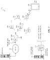
- FIG. 1 shows one embodiment of a point-to-point, point-to-multi-point or multi-point to multi-point wireless communication network.
- the network 100 includes a number of destination nodes (DN) 102a, 102b, 102c, 102d, etc. and a number of client nodes (CN) 104a, 104b, etc.
- the destination nodes transmit IP or other data packets between themselves and to the client nodes.
- the client nodes transmit and receive data such as IP packets between themselves and the destination nodes as well as to a number of end users 106 (wireless-enabled devices such as computers, tablets, smart phones, household appliances, or any other device capable of transmitting and receiving wireless data).
- end users 106 wireless-enabled devices such as computers, tablets, smart phones, household appliances, or any other device capable of transmitting and receiving wireless data.
- the destination nodes 102 are mounted on utility poles or on buildings and can transmit wireless signals approximately 200-300 meters, depending on conditions.
- the client nodes 104 are generally located in retail/office establishments or in homes in order to transmit and receive wireless data to and from the end users 106.
- the wireless data are IP packets that are sent according to a standardized protocol such as IEEE 802.11 ad.
- IEEE 802.11 ad a standardized protocol
- any number of other protocols could be used that include both standards-based and non-standards-based protocols.
- At least one destination node (e.g., node 102a) is coupled to a physical cable that carries data to and from a computer communication link 108 (e.g., the Internet or a private communication link).
- a computer communication link 108 e.g., the Internet or a private communication link.
- Data packets that are destined for an end user 106 are received from the communication link and transmitted via one or more routes to the client node 104b, which is in communication with the end user 106.
- packets may be sent via a first route via nodes DN 1 ->DN 3 ->CN 1 or via a second route including nodes DN 1 ->DN 2 ->CN 1 , depending on the radio frequency path conditions that may exist at any time.
- the destination and client nodes In order to establish a communication link between each of the nodes as well as to minimize interference between nodes, and to increase the throughput of the network, the destination and client nodes generally include multiple antennas that can be used to direct the transmit and receive directions of the node by beamforming.
- the nodes include a transceiver and an antenna array that includes multiple antennas that can be used to direct the transmit and receive directions of the node by beamforming.
- a processor in the node executes instructions that direct a beamformer in the node to selectively weight and delay transmitted signals in order to direct the main lobe (i.e., the bulk of the transmitted signal power) in a desired direction.
- destination node DN1 102a can beamform its transmitted and received signals in a number of different directions 103a, 103b, 103c.
- destination node DN 3 102c can beamform its transmitted and received signals in directions 103d and 103e.
- the best communication path between destination nodes DN 1 and DN 3 is determined by selecting the best transmit and receive beamforming directions for each node in order to complete the communication link.
- the transmit and receive beamforming direction pairs between two nodes in which a communication link can be completed are referred to herein as "micro-routes.”
- transmissions in the wireless network are carried on a nonregulated 60 GHz radio frequency spectrum band.
- the ability to transmit and receive wireless data is influenced by changing atmospheric conditions (wind, rain, etc.) or by interfering objects (e.g., buses, tree limbs, or other objects passing in and out of the line of sight).
- the best communication path between nodes may not always be when the transmit and receive beamforming directions are aligned along the line of sight. Therefore, the best micro-route to complete a communication link between a transmitter and a receiver node in the network may change over time as local propagation conditions vary.
- a cloud controller computer 110 includes a database 112 that stores a list of possible routes and micro-routes that have been determined to work between the various nodes of the network.
- the cloud computer 110 can communicate with each of the nodes by sending packets that are addressed to the nodes in order to control the overall operation of the network.
- Such communications can include routing tables that inform the nodes how packets should be sent through the network to reach any particular node in the network.
- destination node DN 1 may have an entry in its routing table for client node CN 2 that says a packet to that node should be routed through destination node DN 4 and not through destination node DN 3 .
- the nodes also store records of the best micro-routes (TX and RX beamforming directions) that can be used to communicate between nodes.
- the disclosed embodiments are directed to improved methods of acquiring and maintaining synchronization between nodes in a wireless communication network.
- a wireless communication system of the type shown in Figure 1 there is no universal time base that is transmitted to each node.
- Each node includes an internal clock that is subject to drift over time. If a node loses communication with another node in the system or is newly added to the network, it is likely that the clock that tells the node when to transmit and receive will be out of synch with the clocks of the other nodes in the network.
- a node joining or re-joining the network will likely not know which RX beamforming directions should be used to receive data from another node. Typically, only a few combinations of TX and RX beamforming directions will work and a node cannot look in every possible angular direction due to RF chip limitations. Finally, the node joining the network may not know anything about the frame size, the periodicity of the data transmissions from the other nodes or the codebook being used by the nodes in the network.
- the disclosed embodiments allow a node in a wireless communication network to acquire network synchronization without knowing one or more of the optimal TX/RX beamforming directions, the frame structure or frame periodicity.
- the disclosed technology allows a determination of which of the N x M possible transmit and receive beamforming direction possibilities are useful to communicate between a transmitting node and a receiving node.
- FIG. 2 shows one embodiment of a training sequence used in a wireless communication network in accordance with one embodiment of the disclosed technology.
- each node in the network is capable of beamforming in seven possible transmit/receive directions.
- this is for illustration purposes only and that the actual network will typically employ greater numbers of beamforming directions.
- a node When a node joins the network, it first begins listening in each of its possible receive beamforming directions for a training packet that is sent by a transmitting node in the network.
- a transmitting node periodically sends training packets in a particular beamforming direction.
- transmit and receive directions are shown as different shadings.
- the transmitter sends training packets in a "blue" direction eight times (BL 1 , BL 2 , BL 3 ...BL 8 ), followed by the transmission of training packets in a "green” direction for eight times (Gr 1 , Gr 2 ...), and so forth until it has sent training packets in each of its transmit directions.
- the unsynchronized receiving node joining the network begins to try and detect a training packet during a receive window that differs in size from the transmit window in which the training packets are transmitted. Therefore, the rate at which the receiver cycles through its possible receive directions differs from the rate at which the transmitter sends its training packets in a single direction. Because the transmitter and the receiver are not in sync, the receive beamforming direction used by the receiving node at the time of each transmission of the training packet will vary. In Figure 2 , it can be seen that a green receive direction Gr 1 is in use just after the second transmission in the blue direction BL 2 . The next time the green receive direction is used (Gr 2 ), it is between transmissions in the TX blue direction.
- This training packet sequence is repeated at periodic intervals, such as once every hour or some other regular time interval, so that a node joining the network does not have to wait too long before it will likely detect a training packet.
- the training packets are sent in a time period that is less than the window of time during which the receiver is listening in any particular direction.
- a training packet 300a and a training packet 300b each have a duration that is less than one TDD time slot.
- the training packets are sent twice in succession.
- Receive windows 304, 306 each have a duration of 2 TDD time slots. This ensures that at least one of the two transmitted training packets will be captured during a receive window regardless of the relative timing of the receive and transmit TDD time slots.
- a training packet 312 includes a known training field 314 (e.g. short training field) that allows a receiver to capture and decode the remainder of the training packet.
- the training packet includes a synchronization code 316 (which may be a separate code or included in the training field 314) that allows the receiver to synchronize itself with the transmitting node in the network.
- Each training packet may also include one or more other types of information such as a code 318 that indicates the frame length or structure of the training packet and a code 320 indicating the periodicity or how often the training packets will be re-transmitted.
- the training packet 312 includes a code 322 that indicates when the receiving packet should respond if it detects a training packet.
- Other types of information 324 that can be included in the training packet include an indication of the particular Tx beam on which the training packet is sent, the index of a double packet, a Golay index (type of error correcting code), an indication of a codebook used by the transmitter and frequency information if the response frequency is different than the transmit frequency.
- a portion 326 of a transmitted training packet 312 is reserved for the transmitter to listen for a response.
- the receiving node joining the network analyzes the packet to recover the synchronization information and synchronize itself to the network.
- the receiving node analyzes the training packet as it is being received to determine the packet structure and periodicity of the training packets. With this information, the receiver synchronizes itself to the transmitting node and can send a signal acknowledging the receipt of the training packet back to the transmitter. Upon receipt of the acknowledge signal, the transmitting node can start transmitting in a synchronous mode, as will be explained below.
- Other embodiments are also possible, such as allowing time for a receiving node to transmit an acknowledgment after all the training packets have been sent in a particular direction.
- a synchronous communication process is then begun in which each of the N x M possible transmit and receive beamforming direction possibilities is tested to determine which ones are useful in establishing a communication link between the nodes.
- the transmitter and receiver may use the same codebook that defines the beamforming direction possibilities.
- the codebooks used by the transmitter and the receiver may be different.
- the codebooks used by the transmitter and receiver for the asynchronous detection of a training packet are different than those used during the synchronous detection of training packets.
- One codebook may be a subset of the other.
- a transmitter transmits training packets N times in each of its N transmit directions. Because signals are being sent between the transmitter and the receiver, the node that is transmitting the training packets can be called the "initiator," and the node that is attempting to receive the training packets can be called the "responder.”
- Figure 4 illustrates one implementation of a method for determining the preferred beamforming directions in accordance with an embodiment of the disclosed technology.
- An initiator transmits training packets to a responder in direction TX 1 N times, followed by transmitting training packets in direction TX 2 N times and so forth until training packets have been transmitted N times in each of the N beamforming directions.
- the responder which is now synchronized to the initiator, listens for the training packets that are sent in beamforming direction TX 1 using each of its receive beamforming directions. For example, the responder first listens in receive direction RX 1 when the initiator transmits a training packet in direction TX 1 . The responder then listens in direction RX 2 when the initiator transmits a second training packet in direction TX1, followed by listening in direction RX 3 and so forth until the initiator transmits N training packets in a particular direction.
- the number of beamforming directions at the initiator and at the responder may the same or may be different.
- the transmitter has finished transmitting the training packets in a particular direction for the responder to send feedback to the initiator.
- the feedback is sent in the receive beamforming direction that gave the best reception.
- the feedback tells the initiator which ones of the N possible receive beamforming directions can be used to detect the training packets.
- the feedback may also include some link measurements (signal strength, interference, etc.) that can be used to determine the quality of the link with a particular TX/RX beamforming direction pair.
- the initiator sends back a feedback acknowledge signal that lets the responder know which of the TX/RX beamforming pairs will be used as possible micro-routes between the nodes and an order to try the pairs in case communication between the nodes is lost. If no feedback signal is received by the initiator, then the initiator assumes the responder cannot hear it in that particular TX beamforming direction and the next TX beamforming direction is tried.
- Figure 5 shows a similar scheme except that a portion of time after each TX training packet is sent is reserved for the responder to transmit a feedback signal.
- the initiator transmits in a first direction for a first time and the responder listens in its first receive direction. A portion of time is reserved after this transmission for the responder to transmit feedback if it has detected the training packet.
- time is reserved for the initiator to send a feedback acknowledge signal that informs the responder which, if any, of the TX/RX beamforming pairs will be used as a micro-route between them.
- the transmit and receive windows for the initiator and responder are each divided into a transmit portion and a receive portion (that may or may not be of equal length). For example, an initiator transmits its training packet to a responder during the first portion of the window and then listens for a packet back from the responder during a second portion of the window. Conversely, the responder receives transmissions during the first portion of the window when the initiator is transmitting and transmits during the second portion of the window when the initiator is listening.
- any transmission containing feedback from the responder back to the initiator takes place on a transmit/receive beamforming direction pair on which a communication link was previously completed. Therefore, in the embodiment shown, the initiator listens in a direction of a previous transmit direction during the second portion of the transmit window.
- the example in Figure 6 illustrates how this works.
- the designation RX1 on the initiator side means the initiator is listening in the same direction as the TX1 transmit direction.
- TX2 means the responder transmits in the same direction as the receive direction RX2, etc.
- the initiator first transmits in direction TX1, and the responder listens in direction RX1 and does not hear the training packet.
- the initiator then transmits a second training packet in direction TX1, and the responder listens in direction RX2 and does detect the training packet with instructions as to when it should respond.
- the beamforming directions are always changing each time a training packet is transmitted and because a feedback signal is transmitted using a transmit/receive beamforming direction pair that can complete the communication link between the nodes, the initiator listens in a previous transmit direction during the second portion of the transmit window.
- a communication path that connected the initiator to the responder is transmit direction TX1 and receive direction RX2. Therefore, during the second portion of the window when the responder is next listening in direction RX2, it transmits its acknowledge signal back to the transmitter in that same direction.
- the initiator is transmitting in direction TX2 but is listening in the direction of the previous transmission, e.g., RX1. Therefore, the feedback signal is transmitted using the beamforming pair TX1-RX2 (viewed from the initiator side) or TX2-RX1 (viewed from the responder side).
- the feedback signal received at the initiator informs the initiator that the training packet was detected when the initiator was transmitting in direction TX1 and the receiver was listening in direction RX2. This information is stored in both the initiator node and the responder node as a possible path on which the two nodes can communicate.
- Processing proceeds in this manner until each of the N x M possibilities of transmit/receive beamforming directions have been tested.
- the responder can detect a training packet, it sends feedback to the initiator to inform the initiator of another transmit/receive beamforming direction pair on which communication can take place.
- the initiator transmits an acknowledge signal back to the responder confirming the transmit/receive beam pairs that can be used as micro-routes. This can be done after transmission of the training packets has been completed in a particular direction or once all N x M training packets have been transmitted.
- the responder does not have to synchronize the order of its receive beamforming directions with any particular order in which the initiator changes its transmit beamforming directions.
- the responder can test its receive directions in a modulo fashion (6, 7, 1, 2, 3, etc.) where the receive direction rolls back to the first direction after the last direction has been tested.
- the number of receive beamforming directions M is selected to be a prime number, e.g., 7, 17, 29, 31, 43, etc.
- Prime numbers of receive beamforming directions are preferred because there is a greatly reduced (theoretically zero) likelihood that duplicate pairs of transmit/receive beamforming directions will be tested between the initiator and the responder provided that the total time drift during the procedure is less than the size of one training packet.
- the number of transmit directions preferably equals the number of receive directions, but this is not required.
- a transmitter may have eight transmit beamforming directions while a receiving node has seven receive beamforming directions. The transmitting node or the control computer may select seven of the eight possible transmit directions to test against the receive beamforming directions based on propagation conditions or on other criteria.
- Figure 7 shows a sequence of steps performed by nodes in a wireless communication network in accordance with one embodiment of the disclosed technology. Although the steps are described in a particular order for ease of explanation, it will be appreciated that the steps could be performed in a different order or that different steps could be performed in order to achieve the functionality described.
- a transmitter periodically begins transmitting double training packets in each beam direction.
- the period between transmissions is preferably different than the rate at which the receiver changes its beamforming receive directions.
- the receiving node that has joined the network begins asynchronously listening for training packets in each of its beamforming directions in sequence until at least one training packet is detected. Once a training packet is detected, the receiver sends feedback to the transmitter and synchronizes itself to the transmitter using the synchronization information contained in the detected training packet at 704.
- the transmitter begins transmitting training packets N times in each of its N transmit directions while the receiver (responder) listens in each of its M receive directions until all desired (typically all N x M transmit/receive beamforming direction but could be less) possibilities have been attempted.
- the responder informs the initiator which transmit/receive beamforming combinations were successful in completing the communication link between the transmitter (initiator) and the receiver (responder).
- the initiator and the responder also may store a list of which TX/RX beamforming pairs should be tried and in which order in case communications between the nodes is lost.
- One or more of the transmit and receive beamforming directions that can complete the communication link are used as possible micro-routes between the nodes.
- successful transmit/receive beamforming pairs between nodes are also transmitted to the cloud controller computer 110 shown in Figure 1 .
- the cloud computer stores the pairs of directions in the database for use in developing route tables that are transmitted to the various nodes in the network.
- Figure 8 is a state diagram showing the operations performed by a responder node in accordance with some disclosed embodiments.
- a client node or destination node is not connected to the network.
- the node attempts to join the wireless network by executing an initialization routine that runs upon installation, as part of a reboot protocol or upon detection that the node has lost its connection to the network.
- the node (now called a responder node) begins the process of attempting to asynchronously detect a training packet from an initiator node. The responder tries to detect a training packet until either a packet is detected or a time out occurs.
- the responder proceeds to state 808 where it sends a feedback message to an installer or to the cloud controller computer 110 (e.g. via a cellular or other non-network communication path) that the node cannot join the network.
- the responder begins listening for training packets in a synchronous mode at state 810.
- the responder node remains in state 810 until each combination of transmit and receive beamforming directions has been tried.
- the responder node transmits to the initiator mode an indication of one or more receive beamforming directions or transmit/receive beamforming direction pairs that can be used to complete a communication link with the responder node.
- the responder node operates in listening mode, such as a constant TDD receive listening mode, for packets in its designated time slot(s). If a request to communicate is received by the responder node, the responder node transmits an association response to the initiator node via the one of the transmit/receive beamforming direction pairs that were determined to complete a communication link between the nodes at state 814.
- listening mode such as a constant TDD receive listening mode
- Figure 9 shows a state diagram of the operation of an initiator node in some embodiments of a wireless communication network.
- a destination node is operating in an active state in the network by sending and receiving packets to other nodes as requested.
- the node begins an asynchronous scan mode in response to a received a pairing command that is generated from a software or hardware timer in the node itself or from a remote location such as the cloud controller computer 110.
- the node may be asked to pair with other nodes in the system on a periodic basis such as once per hour, once every ten minutes or at some other interval.
- the cloud controller computer 110 instructs the initiator to begin the pairing processes after the cloud controller computer receives an indication that a node wants to join the network.
- the initiator node transmits training packets in a number of transmit beamforming directions that can be detected by a responder node.
- the initiator node continues to transmit the training packets in the asynchronous mode until a signal is received from a responder node that it has detected a training packet or a time out occurs. If a time out occurs, the initiator node sends a message at state 906 to a cloud controller computer 110 indicating that no responder node has detected a training packet within the time period allowed.
- the initiator node begins a synchronous mode scan at state 908 by transmitting training packets in each of a number of transmit beamforming directions. In some embodiments, the initiator remains in state 908 until all transmit beamforming directions have be tested against all receive beamforming directions.
- the initiator node sends a list or ranking of the transmit/receive beamforming directions to be used in communications between the initiator node and the responder node. The list/ranking may be determined at the initiator node or may be received from the cloud controller computer 110.
- the initiator node when the initiator node has traffic or messages for the responder node, the initiator node sends an association request to the responder node to communicate using one or more of the transmit/receive beamforming pairs that were determined to complete a communication link between the nodes.
- one or more of the TX/RX beamforming pairs are used to transmit data packets between the nodes.
- Embodiments of the subject matter and the operations described in this specification can be implemented in digital electronic circuitry or in computer software, firmware, or hardware, including the structures disclosed in this specification and their structural equivalents, or in combinations of one or more of them.
- Embodiments of the subject matter described in this specification can be implemented as one or more computer programs, i.e., one or more modules of computer program instructions, encoded on a computer storage medium for execution by, or to control the operation of, data processing apparatus.
- a computer storage medium can be, or can be included in, a computer-readable storage device, a computer-readable storage substrate, a random or serial access memory array or device, or a combination of one or more of them.
- a computer storage medium is not a propagated signal, a computer storage medium can be a source or destination of computer program instructions encoded in an artificially generated propagated signal.
- the computer storage medium also can be, or can be included in, one or more separate physical components or media (e.g., multiple CDs, disks, or other storage devices).
- the operations described in this specification can be implemented as operations performed by a data processing apparatus on data stored on one or more computer-readable storage devices or received from other sources.
- processor encompasses all kinds of apparatus, devices, and machines for processing data, including by way of example a programmable processor, a computer, a system on a chip, or multiple ones, or combinations, of the foregoing.
- the apparatus can include special purpose logic circuitry, e.g., an FPGA (field programmable gate array) or an ASIC (application-specific integrated circuit).
- the apparatus also can include, in addition to hardware, code that creates an execution environment for the computer program in question, e.g., code that constitutes processor firmware, a protocol stack, a database management system, an operating system, a cross-platform runtime environment, a virtual machine, or a combination of one or more of them.
- the apparatus and execution environment can realize various different computing model infrastructures, such as web services, distributed computing, and grid computing infrastructures.
- a computer program (also known as a program, software, software application, script, or code) can be written in any form of programming language, including compiled or interpreted languages and declarative or procedural languages, and it can be deployed in any form, including as a stand-alone program or as a module, component, subroutine, object, or other unit suitable for use in a computing environment.
- a computer program may, but need not, correspond to a file in a file system.
- a program can be stored in a portion of a file that holds other programs or data (e.g., one or more scripts stored in a markup language document), in a single file dedicated to the program in question, or in multiple coordinated files (e.g., files that store one or more modules, subprograms, or portions of code).
- a computer program can be deployed to be executed on one computer or on multiple computers that are located at one site or distributed across multiple sites and interconnected by a communication network.
- the processes and logic flows described in this specification can be performed by one or more programmable processors executing one or more computer programs to perform actions by operating on input data and generating output.
- the processes and logic flows can also be performed by, and apparatus can also be implemented as, special purpose logic circuitry, e.g., an FPGA or an ASIC.
- processors suitable for the execution of a computer program include, by way of example, both general and special purpose microprocessors and any one or more processors of any kind of digital computer.
- a processor will receive instructions and data from a read-only memory or a random-access memory or both.
- the essential elements of a computer are a processor for performing actions in accordance with instructions and one or more memory devices for storing instructions and data.
- a computer will also include, or be operatively coupled to receive data from or transfer data to (or both), one or more mass storage devices for storing data, e.g., magnetic, magneto-optical disks, or optical disks.
- Devices suitable for storing computer program instructions and data include all forms of nonvolatile memory, media, and memory devices, including by way of example semiconductor memory devices, e.g., EPROM, EEPROM, and flash memory devices; magnetic disks, e.g., internal hard disks or removable disks; magneto-optical disks; and CD-ROM and DVD-ROM disks.
- semiconductor memory devices e.g., EPROM, EEPROM, and flash memory devices
- magnetic disks e.g., internal hard disks or removable disks
- magneto-optical disks e.g., CD-ROM and DVD-ROM disks.
- the processor and the memory can be supplemented by, or incorporated in, special-purpose logic circuitry.
Landscapes
- Engineering & Computer Science (AREA)
- Computer Networks & Wireless Communication (AREA)
- Signal Processing (AREA)
- Mobile Radio Communication Systems (AREA)
- Small-Scale Networks (AREA)
Priority Applications (1)
| Application Number | Priority Date | Filing Date | Title |
|---|---|---|---|
| EP23177118.9A EP4236499A3 (de) | 2015-12-30 | 2016-12-06 | Verbindungserfassung in drahtloskommunikationssystemen |
Applications Claiming Priority (4)
| Application Number | Priority Date | Filing Date | Title |
|---|---|---|---|
| US201562273381P | 2015-12-30 | 2015-12-30 | |
| US14/986,471 US9698885B1 (en) | 2015-12-31 | 2015-12-31 | Link acquistion in directional wireless systems |
| PCT/US2016/065194 WO2017116634A1 (en) | 2015-12-30 | 2016-12-06 | Link acquisition in directional wireless systems |
| EP16882276.5A EP3335385B1 (de) | 2015-12-30 | 2016-12-06 | Verknüpfungserfassung in direktionalen drahtlosen systemen |
Related Parent Applications (2)
| Application Number | Title | Priority Date | Filing Date |
|---|---|---|---|
| EP16882276.5A Division EP3335385B1 (de) | 2015-12-30 | 2016-12-06 | Verknüpfungserfassung in direktionalen drahtlosen systemen |
| EP16882276.5A Division-Into EP3335385B1 (de) | 2015-12-30 | 2016-12-06 | Verknüpfungserfassung in direktionalen drahtlosen systemen |
Related Child Applications (2)
| Application Number | Title | Priority Date | Filing Date |
|---|---|---|---|
| EP23177118.9A Division EP4236499A3 (de) | 2015-12-30 | 2016-12-06 | Verbindungserfassung in drahtloskommunikationssystemen |
| EP23177118.9A Division-Into EP4236499A3 (de) | 2015-12-30 | 2016-12-06 | Verbindungserfassung in drahtloskommunikationssystemen |
Publications (2)
| Publication Number | Publication Date |
|---|---|
| EP3852312A1 true EP3852312A1 (de) | 2021-07-21 |
| EP3852312B1 EP3852312B1 (de) | 2023-07-19 |
Family
ID=59225485
Family Applications (4)
| Application Number | Title | Priority Date | Filing Date |
|---|---|---|---|
| EP23177118.9A Withdrawn EP4236499A3 (de) | 2015-12-30 | 2016-12-06 | Verbindungserfassung in drahtloskommunikationssystemen |
| EP21161215.5A Active EP3852312B1 (de) | 2015-12-30 | 2016-12-06 | Verbindungserfassung in drahtloskommunikationssystemen |
| EP16882276.5A Active EP3335385B1 (de) | 2015-12-30 | 2016-12-06 | Verknüpfungserfassung in direktionalen drahtlosen systemen |
| EP19201791.1A Not-in-force EP3609133B1 (de) | 2015-12-30 | 2016-12-06 | Verknüpfungserfassung in direktionalen drahtlosen systemen |
Family Applications Before (1)
| Application Number | Title | Priority Date | Filing Date |
|---|---|---|---|
| EP23177118.9A Withdrawn EP4236499A3 (de) | 2015-12-30 | 2016-12-06 | Verbindungserfassung in drahtloskommunikationssystemen |
Family Applications After (2)
| Application Number | Title | Priority Date | Filing Date |
|---|---|---|---|
| EP16882276.5A Active EP3335385B1 (de) | 2015-12-30 | 2016-12-06 | Verknüpfungserfassung in direktionalen drahtlosen systemen |
| EP19201791.1A Not-in-force EP3609133B1 (de) | 2015-12-30 | 2016-12-06 | Verknüpfungserfassung in direktionalen drahtlosen systemen |
Country Status (3)
| Country | Link |
|---|---|
| EP (4) | EP4236499A3 (de) |
| CN (1) | CN108292945B (de) |
| WO (1) | WO2017116634A1 (de) |
Families Citing this family (1)
| Publication number | Priority date | Publication date | Assignee | Title |
|---|---|---|---|---|
| CN119788140B (zh) * | 2025-03-04 | 2025-05-27 | 睿能科技(北京)有限公司 | 通过多通道数字波束系统进行信号处理的方法及系统 |
Citations (3)
| Publication number | Priority date | Publication date | Assignee | Title |
|---|---|---|---|---|
| US20100056062A1 (en) * | 2008-08-26 | 2010-03-04 | Hongyuan Zhang | Beamforming by Sector Sweeping |
| US20100164805A1 (en) * | 2008-12-31 | 2010-07-01 | Huaning Niu | Arrangements for beam refinement in a wireless network |
| US20100214169A1 (en) * | 2009-02-23 | 2010-08-26 | Nokia Corporation | Beamforming training for functionally-limited apparatuses |
Family Cites Families (11)
| Publication number | Priority date | Publication date | Assignee | Title |
|---|---|---|---|---|
| US20070189412A1 (en) * | 2006-02-15 | 2007-08-16 | Samsung Electronics Co., Ltd. | Method and system for sounding packet exchange in wireless communication systems |
| US8040856B2 (en) * | 2006-12-04 | 2011-10-18 | Samsung Electronics Co., Ltd. | System and method for wireless communication of uncompressed high definition video data using a beamforming acquisition protocol |
| US20100118802A1 (en) * | 2008-11-12 | 2010-05-13 | Qualcomm Incorporated | Method and apparatus for directional association in a wireless communications system |
| CN102598532B (zh) * | 2009-11-04 | 2015-05-06 | 日本电气株式会社 | 无线电通信系统的控制方法、无线电通信系统和无线电通信装置 |
| US8437333B2 (en) * | 2010-07-06 | 2013-05-07 | Stmicroelectronics, Inc. | Contention based period beamforming |
| KR101656083B1 (ko) | 2011-09-15 | 2016-09-09 | 한국전자통신연구원 | 근거리 무선 통신 시스템에서의 수신 동기 획득 방법 및 그 장치 |
| JP6190889B2 (ja) * | 2012-11-09 | 2017-08-30 | インターデイジタル パテント ホールディングス インコーポレイテッド | ビーム形成方法およびビームを使用するための方法 |
| EP2988431B1 (de) * | 2013-06-28 | 2018-11-14 | Chung-Ang University Industry-Academy Cooperation Foundation | Strahltrainingsvorrichtung und -verfahren |
| US9860893B2 (en) * | 2013-11-19 | 2018-01-02 | Intel IP Corporation | Frame structure with reduced signal field and method for high-efficiency Wi-Fi (HEW) communication |
| JP6381233B2 (ja) * | 2014-02-28 | 2018-08-29 | パナソニック株式会社 | 無線通信方法及び無線通信システム |
| US9474013B2 (en) * | 2014-06-16 | 2016-10-18 | Qualcomm Incorporated | Method and apparatus for connection point discovery and association in a directional wireless network |
-
2016
- 2016-12-06 EP EP23177118.9A patent/EP4236499A3/de not_active Withdrawn
- 2016-12-06 EP EP21161215.5A patent/EP3852312B1/de active Active
- 2016-12-06 WO PCT/US2016/065194 patent/WO2017116634A1/en not_active Ceased
- 2016-12-06 EP EP16882276.5A patent/EP3335385B1/de active Active
- 2016-12-06 CN CN201680068673.8A patent/CN108292945B/zh not_active Expired - Fee Related
- 2016-12-06 EP EP19201791.1A patent/EP3609133B1/de not_active Not-in-force
Patent Citations (3)
| Publication number | Priority date | Publication date | Assignee | Title |
|---|---|---|---|---|
| US20100056062A1 (en) * | 2008-08-26 | 2010-03-04 | Hongyuan Zhang | Beamforming by Sector Sweeping |
| US20100164805A1 (en) * | 2008-12-31 | 2010-07-01 | Huaning Niu | Arrangements for beam refinement in a wireless network |
| US20100214169A1 (en) * | 2009-02-23 | 2010-08-26 | Nokia Corporation | Beamforming training for functionally-limited apparatuses |
Also Published As
| Publication number | Publication date |
|---|---|
| CN108292945A (zh) | 2018-07-17 |
| EP3609133B1 (de) | 2022-02-09 |
| CN108292945B (zh) | 2021-11-12 |
| EP3609133A1 (de) | 2020-02-12 |
| EP4236499A3 (de) | 2023-09-13 |
| WO2017116634A1 (en) | 2017-07-06 |
| EP3335385A1 (de) | 2018-06-20 |
| EP4236499A2 (de) | 2023-08-30 |
| EP3335385B1 (de) | 2021-08-11 |
| EP3852312B1 (de) | 2023-07-19 |
| EP3335385A4 (de) | 2019-03-20 |
Similar Documents
| Publication | Publication Date | Title |
|---|---|---|
| CN107079309B (zh) | 无线通信系统中的信道接入方法和装置 | |
| US10574330B2 (en) | Link acquisition in wireless communication systems | |
| EP2727392B1 (de) | Verteilter positionierungsmechanismus für drahtlose kommunikationsvorrichtungen | |
| CN118355618A (zh) | 用于新无线电非地面网络中的同步增强的方法和系统 | |
| JP2021509241A (ja) | Wlan分散ネットワークにおけるマルチバンドミリメートル波の発見 | |
| CN101778467A (zh) | Td-scdma系统中实现接入点同步定时的方法 | |
| JP2008228177A (ja) | 無線装置 | |
| JP7788001B2 (ja) | 適応型相変化デバイスを使用した多重入出力伝送 | |
| CN109996325B (zh) | 一种无线传感器网络的时钟同步系统及方法 | |
| CN116684978A (zh) | 通信节点及其操作方法、无线通信系统和存储系统 | |
| EP3609133B1 (de) | Verknüpfungserfassung in direktionalen drahtlosen systemen | |
| CN105790817B (zh) | 一种基于定向天线的tdma自组网波束选择方法 | |
| US20160227494A1 (en) | Method and apparatus to determine a transmission time of a wireless data frame | |
| CN110661587B (zh) | 发送信号的方法及装置 | |
| CN108601079B (zh) | 定时方法、装置、通信节点设备及计算机存储介质 | |
| US20180097857A1 (en) | Wireless conferencing system and method for configuring same | |
| US12557049B1 (en) | Time division duplexing synchronization in wireless mesh networks | |
| EP4260616B1 (de) | Asymmetrische ausbreitungsverzögerungsdetektion und reaktion für drahtlose netzwerke | |
| CN114731181A (zh) | 一种波束训练方法及装置 | |
| US20260121694A1 (en) | Reconfigurable intelligent surface and method of controlling reconfigurable intelligent surface | |
| US20250261137A1 (en) | Timing grid for decentralized synchronization in wireless distributed networks | |
| US20250247802A1 (en) | Inter-cluster synchronization via relay anchors | |
| KR101458446B1 (ko) | 복수의 기지국으로 레인징 신호를 전송하는 레인징 시스템 | |
| GB2496133A (en) | Performing synchronised action between nodes in a wireless communication network | |
| KR20260046394A (ko) | 초광대역 통신을 위한 클러스터에서 앵커의 동작 |
Legal Events
| Date | Code | Title | Description |
|---|---|---|---|
| PUAI | Public reference made under article 153(3) epc to a published international application that has entered the european phase |
Free format text: ORIGINAL CODE: 0009012 |
|
| STAA | Information on the status of an ep patent application or granted ep patent |
Free format text: STATUS: THE APPLICATION HAS BEEN PUBLISHED |
|
| AC | Divisional application: reference to earlier application |
Ref document number: 3335385 Country of ref document: EP Kind code of ref document: P |
|
| AK | Designated contracting states |
Kind code of ref document: A1 Designated state(s): AL AT BE BG CH CY CZ DE DK EE ES FI FR GB GR HR HU IE IS IT LI LT LU LV MC MK MT NL NO PL PT RO RS SE SI SK SM TR |
|
| STAA | Information on the status of an ep patent application or granted ep patent |
Free format text: STATUS: REQUEST FOR EXAMINATION WAS MADE |
|
| 17P | Request for examination filed |
Effective date: 20211221 |
|
| RBV | Designated contracting states (corrected) |
Designated state(s): AL AT BE BG CH CY CZ DE DK EE ES FI FR GB GR HR HU IE IS IT LI LT LU LV MC MK MT NL NO PL PT RO RS SE SI SK SM TR |
|
| RAP3 | Party data changed (applicant data changed or rights of an application transferred) |
Owner name: META PLATFORMS, INC. |
|
| REG | Reference to a national code |
Ref country code: DE Ref legal event code: R079 Free format text: PREVIOUS MAIN CLASS: H04L0012260000 Ipc: H04B0007080000 Ref document number: 602016081280 Country of ref document: DE |
|
| GRAP | Despatch of communication of intention to grant a patent |
Free format text: ORIGINAL CODE: EPIDOSNIGR1 |
|
| STAA | Information on the status of an ep patent application or granted ep patent |
Free format text: STATUS: GRANT OF PATENT IS INTENDED |
|
| RIC1 | Information provided on ipc code assigned before grant |
Ipc: H04W 56/00 20090101ALI20230117BHEP Ipc: H04B 7/08 20060101AFI20230117BHEP |
|
| INTG | Intention to grant announced |
Effective date: 20230202 |
|
| GRAS | Grant fee paid |
Free format text: ORIGINAL CODE: EPIDOSNIGR3 |
|
| GRAA | (expected) grant |
Free format text: ORIGINAL CODE: 0009210 |
|
| STAA | Information on the status of an ep patent application or granted ep patent |
Free format text: STATUS: THE PATENT HAS BEEN GRANTED |
|
| P01 | Opt-out of the competence of the unified patent court (upc) registered |
Effective date: 20230525 |
|
| AC | Divisional application: reference to earlier application |
Ref document number: 3335385 Country of ref document: EP Kind code of ref document: P |
|
| AK | Designated contracting states |
Kind code of ref document: B1 Designated state(s): AL AT BE BG CH CY CZ DE DK EE ES FI FR GB GR HR HU IE IS IT LI LT LU LV MC MK MT NL NO PL PT RO RS SE SI SK SM TR |
|
| REG | Reference to a national code |
Ref country code: GB Ref legal event code: FG4D |
|
| REG | Reference to a national code |
Ref country code: CH Ref legal event code: EP |
|
| REG | Reference to a national code |
Ref country code: DE Ref legal event code: R096 Ref document number: 602016081280 Country of ref document: DE |
|
| REG | Reference to a national code |
Ref country code: IE Ref legal event code: FG4D |
|
| REG | Reference to a national code |
Ref country code: LT Ref legal event code: MG9D |
|
| REG | Reference to a national code |
Ref country code: NL Ref legal event code: MP Effective date: 20230719 |
|
| REG | Reference to a national code |
Ref country code: AT Ref legal event code: MK05 Ref document number: 1590518 Country of ref document: AT Kind code of ref document: T Effective date: 20230719 |
|
| PG25 | Lapsed in a contracting state [announced via postgrant information from national office to epo] |
Ref country code: NL Free format text: LAPSE BECAUSE OF FAILURE TO SUBMIT A TRANSLATION OF THE DESCRIPTION OR TO PAY THE FEE WITHIN THE PRESCRIBED TIME-LIMIT Effective date: 20230719 |
|
| PG25 | Lapsed in a contracting state [announced via postgrant information from national office to epo] |
Ref country code: GR Free format text: LAPSE BECAUSE OF FAILURE TO SUBMIT A TRANSLATION OF THE DESCRIPTION OR TO PAY THE FEE WITHIN THE PRESCRIBED TIME-LIMIT Effective date: 20231020 |
|
| PGFP | Annual fee paid to national office [announced via postgrant information from national office to epo] |
Ref country code: GB Payment date: 20231229 Year of fee payment: 8 |
|
| PG25 | Lapsed in a contracting state [announced via postgrant information from national office to epo] |
Ref country code: IS Free format text: LAPSE BECAUSE OF FAILURE TO SUBMIT A TRANSLATION OF THE DESCRIPTION OR TO PAY THE FEE WITHIN THE PRESCRIBED TIME-LIMIT Effective date: 20231119 |
|
| PG25 | Lapsed in a contracting state [announced via postgrant information from national office to epo] |
Ref country code: SE Free format text: LAPSE BECAUSE OF FAILURE TO SUBMIT A TRANSLATION OF THE DESCRIPTION OR TO PAY THE FEE WITHIN THE PRESCRIBED TIME-LIMIT Effective date: 20230719 Ref country code: RS Free format text: LAPSE BECAUSE OF FAILURE TO SUBMIT A TRANSLATION OF THE DESCRIPTION OR TO PAY THE FEE WITHIN THE PRESCRIBED TIME-LIMIT Effective date: 20230719 Ref country code: PT Free format text: LAPSE BECAUSE OF FAILURE TO SUBMIT A TRANSLATION OF THE DESCRIPTION OR TO PAY THE FEE WITHIN THE PRESCRIBED TIME-LIMIT Effective date: 20231120 Ref country code: NO Free format text: LAPSE BECAUSE OF FAILURE TO SUBMIT A TRANSLATION OF THE DESCRIPTION OR TO PAY THE FEE WITHIN THE PRESCRIBED TIME-LIMIT Effective date: 20231019 Ref country code: LV Free format text: LAPSE BECAUSE OF FAILURE TO SUBMIT A TRANSLATION OF THE DESCRIPTION OR TO PAY THE FEE WITHIN THE PRESCRIBED TIME-LIMIT Effective date: 20230719 Ref country code: LT Free format text: LAPSE BECAUSE OF FAILURE TO SUBMIT A TRANSLATION OF THE DESCRIPTION OR TO PAY THE FEE WITHIN THE PRESCRIBED TIME-LIMIT Effective date: 20230719 Ref country code: IS Free format text: LAPSE BECAUSE OF FAILURE TO SUBMIT A TRANSLATION OF THE DESCRIPTION OR TO PAY THE FEE WITHIN THE PRESCRIBED TIME-LIMIT Effective date: 20231119 Ref country code: HR Free format text: LAPSE BECAUSE OF FAILURE TO SUBMIT A TRANSLATION OF THE DESCRIPTION OR TO PAY THE FEE WITHIN THE PRESCRIBED TIME-LIMIT Effective date: 20230719 Ref country code: GR Free format text: LAPSE BECAUSE OF FAILURE TO SUBMIT A TRANSLATION OF THE DESCRIPTION OR TO PAY THE FEE WITHIN THE PRESCRIBED TIME-LIMIT Effective date: 20231020 Ref country code: FI Free format text: LAPSE BECAUSE OF FAILURE TO SUBMIT A TRANSLATION OF THE DESCRIPTION OR TO PAY THE FEE WITHIN THE PRESCRIBED TIME-LIMIT Effective date: 20230719 Ref country code: AT Free format text: LAPSE BECAUSE OF FAILURE TO SUBMIT A TRANSLATION OF THE DESCRIPTION OR TO PAY THE FEE WITHIN THE PRESCRIBED TIME-LIMIT Effective date: 20230719 |
|
| PG25 | Lapsed in a contracting state [announced via postgrant information from national office to epo] |
Ref country code: PL Free format text: LAPSE BECAUSE OF FAILURE TO SUBMIT A TRANSLATION OF THE DESCRIPTION OR TO PAY THE FEE WITHIN THE PRESCRIBED TIME-LIMIT Effective date: 20230719 |
|
| REG | Reference to a national code |
Ref country code: DE Ref legal event code: R097 Ref document number: 602016081280 Country of ref document: DE |
|
| PG25 | Lapsed in a contracting state [announced via postgrant information from national office to epo] |
Ref country code: ES Free format text: LAPSE BECAUSE OF FAILURE TO SUBMIT A TRANSLATION OF THE DESCRIPTION OR TO PAY THE FEE WITHIN THE PRESCRIBED TIME-LIMIT Effective date: 20230719 |
|
| PG25 | Lapsed in a contracting state [announced via postgrant information from national office to epo] |
Ref country code: SM Free format text: LAPSE BECAUSE OF FAILURE TO SUBMIT A TRANSLATION OF THE DESCRIPTION OR TO PAY THE FEE WITHIN THE PRESCRIBED TIME-LIMIT Effective date: 20230719 Ref country code: RO Free format text: LAPSE BECAUSE OF FAILURE TO SUBMIT A TRANSLATION OF THE DESCRIPTION OR TO PAY THE FEE WITHIN THE PRESCRIBED TIME-LIMIT Effective date: 20230719 Ref country code: ES Free format text: LAPSE BECAUSE OF FAILURE TO SUBMIT A TRANSLATION OF THE DESCRIPTION OR TO PAY THE FEE WITHIN THE PRESCRIBED TIME-LIMIT Effective date: 20230719 Ref country code: EE Free format text: LAPSE BECAUSE OF FAILURE TO SUBMIT A TRANSLATION OF THE DESCRIPTION OR TO PAY THE FEE WITHIN THE PRESCRIBED TIME-LIMIT Effective date: 20230719 Ref country code: DK Free format text: LAPSE BECAUSE OF FAILURE TO SUBMIT A TRANSLATION OF THE DESCRIPTION OR TO PAY THE FEE WITHIN THE PRESCRIBED TIME-LIMIT Effective date: 20230719 Ref country code: CZ Free format text: LAPSE BECAUSE OF FAILURE TO SUBMIT A TRANSLATION OF THE DESCRIPTION OR TO PAY THE FEE WITHIN THE PRESCRIBED TIME-LIMIT Effective date: 20230719 Ref country code: SK Free format text: LAPSE BECAUSE OF FAILURE TO SUBMIT A TRANSLATION OF THE DESCRIPTION OR TO PAY THE FEE WITHIN THE PRESCRIBED TIME-LIMIT Effective date: 20230719 |
|
| PGFP | Annual fee paid to national office [announced via postgrant information from national office to epo] |
Ref country code: DE Payment date: 20231222 Year of fee payment: 8 |
|
| PLBE | No opposition filed within time limit |
Free format text: ORIGINAL CODE: 0009261 |
|
| STAA | Information on the status of an ep patent application or granted ep patent |
Free format text: STATUS: NO OPPOSITION FILED WITHIN TIME LIMIT |
|
| PG25 | Lapsed in a contracting state [announced via postgrant information from national office to epo] |
Ref country code: IT Free format text: LAPSE BECAUSE OF FAILURE TO SUBMIT A TRANSLATION OF THE DESCRIPTION OR TO PAY THE FEE WITHIN THE PRESCRIBED TIME-LIMIT Effective date: 20230719 |
|
| 26N | No opposition filed |
Effective date: 20240422 |
|
| PG25 | Lapsed in a contracting state [announced via postgrant information from national office to epo] |
Ref country code: SI Free format text: LAPSE BECAUSE OF FAILURE TO SUBMIT A TRANSLATION OF THE DESCRIPTION OR TO PAY THE FEE WITHIN THE PRESCRIBED TIME-LIMIT Effective date: 20230719 |
|
| REG | Reference to a national code |
Ref country code: CH Ref legal event code: PL |
|
| PG25 | Lapsed in a contracting state [announced via postgrant information from national office to epo] |
Ref country code: LU Free format text: LAPSE BECAUSE OF NON-PAYMENT OF DUE FEES Effective date: 20231206 |
|
| PG25 | Lapsed in a contracting state [announced via postgrant information from national office to epo] |
Ref country code: MC Free format text: LAPSE BECAUSE OF FAILURE TO SUBMIT A TRANSLATION OF THE DESCRIPTION OR TO PAY THE FEE WITHIN THE PRESCRIBED TIME-LIMIT Effective date: 20230719 |
|
| REG | Reference to a national code |
Ref country code: BE Ref legal event code: MM Effective date: 20231231 |
|
| PG25 | Lapsed in a contracting state [announced via postgrant information from national office to epo] |
Ref country code: MC Free format text: LAPSE BECAUSE OF FAILURE TO SUBMIT A TRANSLATION OF THE DESCRIPTION OR TO PAY THE FEE WITHIN THE PRESCRIBED TIME-LIMIT Effective date: 20230719 Ref country code: LU Free format text: LAPSE BECAUSE OF NON-PAYMENT OF DUE FEES Effective date: 20231206 |
|
| REG | Reference to a national code |
Ref country code: IE Ref legal event code: MM4A |
|
| PG25 | Lapsed in a contracting state [announced via postgrant information from national office to epo] |
Ref country code: IE Free format text: LAPSE BECAUSE OF NON-PAYMENT OF DUE FEES Effective date: 20231206 |
|
| PG25 | Lapsed in a contracting state [announced via postgrant information from national office to epo] |
Ref country code: BE Free format text: LAPSE BECAUSE OF NON-PAYMENT OF DUE FEES Effective date: 20231231 |
|
| PG25 | Lapsed in a contracting state [announced via postgrant information from national office to epo] |
Ref country code: FR Free format text: LAPSE BECAUSE OF NON-PAYMENT OF DUE FEES Effective date: 20231231 |
|
| PG25 | Lapsed in a contracting state [announced via postgrant information from national office to epo] |
Ref country code: CH Free format text: LAPSE BECAUSE OF NON-PAYMENT OF DUE FEES Effective date: 20231231 |
|
| PG25 | Lapsed in a contracting state [announced via postgrant information from national office to epo] |
Ref country code: IE Free format text: LAPSE BECAUSE OF NON-PAYMENT OF DUE FEES Effective date: 20231206 Ref country code: FR Free format text: LAPSE BECAUSE OF NON-PAYMENT OF DUE FEES Effective date: 20231231 Ref country code: CH Free format text: LAPSE BECAUSE OF NON-PAYMENT OF DUE FEES Effective date: 20231231 Ref country code: BE Free format text: LAPSE BECAUSE OF NON-PAYMENT OF DUE FEES Effective date: 20231231 |
|
| PG25 | Lapsed in a contracting state [announced via postgrant information from national office to epo] |
Ref country code: BG Free format text: LAPSE BECAUSE OF FAILURE TO SUBMIT A TRANSLATION OF THE DESCRIPTION OR TO PAY THE FEE WITHIN THE PRESCRIBED TIME-LIMIT Effective date: 20230719 |
|
| PG25 | Lapsed in a contracting state [announced via postgrant information from national office to epo] |
Ref country code: BG Free format text: LAPSE BECAUSE OF FAILURE TO SUBMIT A TRANSLATION OF THE DESCRIPTION OR TO PAY THE FEE WITHIN THE PRESCRIBED TIME-LIMIT Effective date: 20230719 |
|
| REG | Reference to a national code |
Ref country code: DE Ref legal event code: R119 Ref document number: 602016081280 Country of ref document: DE |
|
| PG25 | Lapsed in a contracting state [announced via postgrant information from national office to epo] |
Ref country code: CY Free format text: LAPSE BECAUSE OF FAILURE TO SUBMIT A TRANSLATION OF THE DESCRIPTION OR TO PAY THE FEE WITHIN THE PRESCRIBED TIME-LIMIT; INVALID AB INITIO Effective date: 20161206 |
|
| PG25 | Lapsed in a contracting state [announced via postgrant information from national office to epo] |
Ref country code: HU Free format text: LAPSE BECAUSE OF FAILURE TO SUBMIT A TRANSLATION OF THE DESCRIPTION OR TO PAY THE FEE WITHIN THE PRESCRIBED TIME-LIMIT; INVALID AB INITIO Effective date: 20161206 |
|
| GBPC | Gb: european patent ceased through non-payment of renewal fee |
Effective date: 20241206 |
|
| PG25 | Lapsed in a contracting state [announced via postgrant information from national office to epo] |
Ref country code: DE Free format text: LAPSE BECAUSE OF NON-PAYMENT OF DUE FEES Effective date: 20250701 |
|
| PG25 | Lapsed in a contracting state [announced via postgrant information from national office to epo] |
Ref country code: GB Free format text: LAPSE BECAUSE OF NON-PAYMENT OF DUE FEES Effective date: 20241206 |
|
| PG25 | Lapsed in a contracting state [announced via postgrant information from national office to epo] |
Ref country code: TR Free format text: LAPSE BECAUSE OF FAILURE TO SUBMIT A TRANSLATION OF THE DESCRIPTION OR TO PAY THE FEE WITHIN THE PRESCRIBED TIME-LIMIT Effective date: 20230719 |