EP3852328A1 - Verfahren, vorrichtung und system zur bestimmung eines leitungslecks - Google Patents
Verfahren, vorrichtung und system zur bestimmung eines leitungslecks Download PDFInfo
- Publication number
- EP3852328A1 EP3852328A1 EP19864222.5A EP19864222A EP3852328A1 EP 3852328 A1 EP3852328 A1 EP 3852328A1 EP 19864222 A EP19864222 A EP 19864222A EP 3852328 A1 EP3852328 A1 EP 3852328A1
- Authority
- EP
- European Patent Office
- Prior art keywords
- relationship
- peer
- route
- autonomous system
- receiving
- Prior art date
- Legal status (The legal status is an assumption and is not a legal conclusion. Google has not performed a legal analysis and makes no representation as to the accuracy of the status listed.)
- Granted
Links
Images




Classifications
-
- H—ELECTRICITY
- H04—ELECTRIC COMMUNICATION TECHNIQUE
- H04L—TRANSMISSION OF DIGITAL INFORMATION, e.g. TELEGRAPHIC COMMUNICATION
- H04L63/00—Network architectures or network communication protocols for network security
- H04L63/14—Network architectures or network communication protocols for network security for detecting or protecting against malicious traffic
- H04L63/1408—Network architectures or network communication protocols for network security for detecting or protecting against malicious traffic by monitoring network traffic
- H04L63/1425—Traffic logging, e.g. anomaly detection
-
- H—ELECTRICITY
- H04—ELECTRIC COMMUNICATION TECHNIQUE
- H04L—TRANSMISSION OF DIGITAL INFORMATION, e.g. TELEGRAPHIC COMMUNICATION
- H04L45/00—Routing or path finding of packets in data switching networks
- H04L45/02—Topology update or discovery
- H04L45/033—Topology update or discovery by updating distance vector protocols
-
- H—ELECTRICITY
- H04—ELECTRIC COMMUNICATION TECHNIQUE
- H04L—TRANSMISSION OF DIGITAL INFORMATION, e.g. TELEGRAPHIC COMMUNICATION
- H04L45/00—Routing or path finding of packets in data switching networks
- H04L45/02—Topology update or discovery
- H04L45/04—Interdomain routing, e.g. hierarchical routing
-
- H—ELECTRICITY
- H04—ELECTRIC COMMUNICATION TECHNIQUE
- H04L—TRANSMISSION OF DIGITAL INFORMATION, e.g. TELEGRAPHIC COMMUNICATION
- H04L45/00—Routing or path finding of packets in data switching networks
- H04L45/70—Routing based on monitoring results
-
- H—ELECTRICITY
- H04—ELECTRIC COMMUNICATION TECHNIQUE
- H04L—TRANSMISSION OF DIGITAL INFORMATION, e.g. TELEGRAPHIC COMMUNICATION
- H04L45/00—Routing or path finding of packets in data switching networks
- H04L45/74—Address processing for routing
-
- H—ELECTRICITY
- H04—ELECTRIC COMMUNICATION TECHNIQUE
- H04L—TRANSMISSION OF DIGITAL INFORMATION, e.g. TELEGRAPHIC COMMUNICATION
- H04L63/00—Network architectures or network communication protocols for network security
- H04L63/14—Network architectures or network communication protocols for network security for detecting or protecting against malicious traffic
-
- H—ELECTRICITY
- H04—ELECTRIC COMMUNICATION TECHNIQUE
- H04L—TRANSMISSION OF DIGITAL INFORMATION, e.g. TELEGRAPHIC COMMUNICATION
- H04L69/00—Network arrangements, protocols or services independent of the application payload and not provided for in the other groups of this subclass
- H04L69/22—Parsing or analysis of headers
Definitions
- the present invention relates to the communications field, and in particular, to a method and system for determining a route leak.
- a route leak means that a transmission range of a route advertisement exceeds an expected range.
- AS autonomous system
- BGP Border Gateway Protocol
- AS advertises a border gateway protocol (Border Gateway Protocol, BGP) route learned by the AS to another AS
- the advertisement violates a routing policy of a route sender AS, a routing policy of a route receiver AS, and/or a routing policy of an AS that the advertisement passes through
- these routing policies may be determined based on business relationships between ASs.
- the business relationships between ASs include: a customer-to-provider (Customer to Provider, C2P for short) relationship, a peer-to-peer (Peer to Peer, P2P for short) relationship, or a provider-to-client (Provider to Customer, P2C for short) relationship.
- C2P Customer to Provider
- P2P peer-to-peer
- P2C Provider to Customer
- a network administrator configures an export policy on each border router of an AS.
- the export policy is configured on a border node R2 of an AS 1.
- the export policy is that a route from an AS 2 can be advertised to an AS 3 but not an AS 4.
- R1 modifies the routing information A, marks in A that A comes from the AS 2, and then transmits the routing information A with the mark to the border node R2 of the AS 1 through an intermediate node of the AS 1.
- the border node R2 determines whether to send A to the AS 4 according to the export policy.
- configuration of R2 is incorrect, the route that should not be sent is sent. Therefore, the route leak occurs.
- a BGP route advertisement protocol needs to be modified, for example, a BGP update message (BGP update message) needs to be modified. This causes a compatibility problem involved in a solution implementation.
- This application provides a method, device, and system for determining a route leak.
- a network monitoring device analyzes a business relationship of receiving and sending routing information between ASs carried in a BMP packet reported by each border node of an autonomous system managed by the network monitoring device. In this way, the network monitoring device can effectively check whether a route leak occurs in the autonomous system managed by network monitoring device.
- an embodiment of the present invention provides a method for determining a route leak, which is applied to a network monitoring device.
- the network monitoring device manages a first autonomous system.
- the method includes: receiving an extended border gateway protocol monitoring protocol (Border Gateway Protocol Monitoring Protocol, BMP) packet sent by a first border node of the first autonomous system and an extended BMP packet sent by a second border node of the first autonomous system; determining, based on the extended BMP packet sent by the first border node and the extended BMP packet sent by the second border node of the first autonomous system, a receiving relationship of a route prefix that has been received by the first border node from a second autonomous system, and a sending relationship of the route prefix that has been sent by the second border node to a third autonomous system, where the receiving relationship is a client-to-provider relationship, a peer-to-peer relationship, or a provider-to-client relationship, and the sending relationship is the client-to-provider relationship, the peer-to-peer relationship, or the
- the receiving relationship of the route prefix is a business relationship between a sender AS of the route prefix and a receiver AS of the route prefix when a border node of the receiver AS receives the route prefix.
- the sending relationship of the route prefix is a business relationship between a sender AS of the route prefix and a receiver AS of the route prefix when a border node of the sender AS of the route prefix sends the route prefix to the receiver AS.
- the network monitoring device determines, based on a BMP packet reported by a route ingress border node of an autonomous system managed by the network monitoring device and a BMP packet reported by a route egress border node of the autonomous system managed by the network monitoring device, a receiving relationship of a route prefix that has been received by the route ingress border node and a sending relationship of a same route prefix that has been sent by the route egress border node.
- a BGP route transmission mechanism does not need to be modified (for example, a BGP update message does not need to be modified). This avoids a compatibility problem involved in a solution implementation.
- the network monitoring device receives a first extended BMP route monitoring packet sent by the first border node.
- the first extended BMP route monitoring packet carries the receiving relationship.
- the network monitoring device receives a second extended BMP route monitoring packet sent by the second border node.
- the second extended BMP route monitoring packet carries the sending relationship.
- the network monitoring device determines the receiving relationship and the sending relationship based on the receiving relationship carried in the first extended BMP route monitoring packet and the sending relationship carried in the second extended BMP route monitoring packet.
- the network monitoring device may directly obtain a receiving relationship and a sending relationship that are of a route prefix from an extended BMP route monitoring packet, and does not need to refer to information about another type of BMP packet. Therefore, for the network monitoring device, workload of comparison analysis is less.
- the network monitoring device receives a first extended BMP peer up notification packet sent by the first border node.
- the first extended BMP peer up notification packet carries a receiving relationship rule for receiving, by the first border node, routing information from the second autonomous system.
- the receiving relationship rule includes receiving based on the client-to-provider relationship, receiving based on the peer-to-peer relationship, or receiving based on the provider-to-client relationship.
- the network monitoring device receives a second extended BMP peer up notification packet sent by the second border node.
- the second extended BMP peer up notification packet carries a sending relationship rule for sending, by the second border node, routing information to the third autonomous system.
- the sending relationship rule includes sending based on the client-to-provider relationship, sending based on the peer-to-peer relationship, or sending based on the provider-to-client relationship.
- the network monitoring device receives a BMP route monitoring packet sent by the second border node.
- the BMP route monitoring packet indicates that a transfer path of the route prefix sequentially includes the second autonomous system, the first autonomous system, and the third autonomous system.
- the network monitoring device determines the receiving relationship and the sending relationship according to the receiving relationship rule carried in the first extended BMP peer up notification packet, the sending relationship rule carried in the second extended BMP peer up notification packet, and the transfer path of the route prefix carried in the BMP route monitoring packet.
- a BMP peer up notification packet is extended to carry a receiving relationship rule and a sending relationship rule. This prevents each BMP route monitoring packet from carrying the receiving relationship and the sending relationship. This is because the peer up notification packet is sent once when a BGP peer relationship is established, and the BMP route monitoring packet is triggered each time a border node receives or sends routing information.
- This design can reduce repeated carrying of business relationship information.
- the network monitoring device may monitor only a BMP route monitoring packet sent by an egress border node. This reduces monitoring workload.
- the network monitoring device receives a first extended BMP peer up notification packet sent by the first border node.
- the first extended BMP peer up notification packet carries a receiving relationship rule for receiving, by the first border node, routing information from the second autonomous system.
- the receiving relationship rule includes receiving based on the client-to-provider relationship, receiving based on the peer-to-peer relationship, or receiving based on the provider-to-client relationship.
- the network monitoring device receives a second extended BMP peer up notification packet sent by the second border node.
- the second extended BMP peer up notification packet carries a sending relationship rule for sending, by the second border node, routing information to the third autonomous system.
- the sending relationship rule includes sending based on the client-to-provider relationship, sending based on the peer-to-peer relationship, or sending based on the provider-to-client relationship.
- the network monitoring device receives a first BMP route monitoring packet sent by the first border node.
- the first BMP route monitoring packet indicates that the first border node has received the route prefix from the second autonomous system.
- the network monitoring device receives a second BMP route monitoring packet sent by the second border node.
- the second BMP route monitoring packet indicates that the second border node has sent the route prefix to the third autonomous system.
- the network monitoring device determines the receiving relationship and the sending relationship according to the receiving relationship rule carried in the first extended BMP peer up notification packet, the sending relationship rule carried in the second extended BMP peer up notification packet, the first BMP route monitoring packet, and the second BMP route monitoring packet.
- the network monitoring device can also determine whether the route prefix is leaked without depending on transmission path information that is in each AS and that is of a route prefix carried in a BMP route monitoring packet.
- the foregoing receiving relationship rule or the foregoing sending relationship rule may be a granularity of a peer autonomous system, and may also be a granularity of the route prefix. The two granularities may coexist, and the granularity of the route prefix has a higher priority. In this way, the receiving relationship rule or the sending relationship rule can be more flexible.
- the network monitoring device After determining that a route leak occurs in the route prefix, the network monitoring device outputs alarm information.
- the alarm information indicates that the route prefix is leaked from the first autonomous system to the third autonomous system. In this way, a network administrator can obtain a prompt of the route leak in time, locate the leaked route prefix and an area in which the route leak occurs, and check an export policy of a border node, to find faulty policy configuration.
- the network monitoring device determines, according to the following rules, whether the route prefix is leaked. If the receiving relationship is the peer-to-peer relationship, and the sending relationship is the peer-to-peer relationship, the network monitoring device determines that the route prefix is leaked. If the receiving relationship is the peer-to-peer relationship, and the sending relationship is the client-to-provider relationship, the network monitoring device determines that the route prefix is leaked. If the receiving relationship is the provider-to-client relationship, and the sending relationship is the peer-to-peer relationship, the network monitoring device determines that the route prefix is leaked. If the receiving relationship is the provider-to-client relationship, and the sending relationship is the client-to-provider relationship, the network monitoring device determines that the route prefix is leaked.
- an embodiment of the present invention provides a method for determining a route leak, which is applied to a routing device.
- the routing device is a border node of a first autonomous system.
- the routing device determines a receiving relationship of a route prefix that has been received from a second autonomous system.
- the receiving relationship is a client-to-provider relationship, a peer-to-peer relationship, or a provider-to-client relationship.
- the routing device generates an extended BMP route monitoring packet.
- the extended BMP route monitoring packet includes the receiving relationship.
- the routing device sends the extended BMP route monitoring packet to a network monitoring device of the first autonomous system.
- the routing device reports, to the network monitoring device, the receiving relationship of the route prefix that has been received from the second autonomous system. This helps the network monitoring device determine, with reference to a sending relationship of the route prefix, whether the route prefix is leaked.
- the routing device obtains a receiving relationship rule for receiving routing information that is from the second autonomous system.
- the receiving relationship rule includes receiving based on the client-to-provider relationship, receiving based on the peer-to-peer relationship, or receiving based on the provider-to-client relationship.
- the routing device receives routing information that is from the second autonomous system and that includes the prefix.
- the routing device determines the receiving relationship according to the receiving relationship rule.
- the receiving relationship rule is configured on the routing device.
- an extension manner of the extended BMP route monitoring packet is to add an extension field, and a packet format of the extension field is a type-length-value format.
- a value of a type field being a first preset value indicates a relationship between a route prefix source autonomous system and a local autonomous system
- the value of the type field being a second preset value indicates a relationship between a local autonomous system and a destination autonomous system to which a route prefix is sent.
- a value of a value field being a third preset value indicates the client-to-provider relationship
- the value of the value field being a fourth preset value indicates the peer-to-peer relationship
- the value of the value field being a fifth preset value indicates the provider-to-client relationship.
- the first preset value is 1, the second preset value is 2, the third preset value is 1, the fourth preset value is 2, and the fifth preset value is 3.
- the value of the type field being a sixth preset value indicates information about a relationship between ASs.
- a format of the value field may be (a sender AS, a receiver AS, a business relationship).
- a value of the business relationship being the third preset value indicates the client-to-provider relationship
- the value of the business relationship being the fourth preset value indicates the peer-to-peer relationship
- the value of the business relationship being the fifth preset value indicates the provider-to-client relationship.
- an embodiment of the present invention provides a method for determining a route leak, which is applied to a routing device.
- the routing device is a border node of a first autonomous system.
- the routing device determines a sending relationship of a route prefix that has been sent to a third autonomous system.
- the sending relationship is a client-to-provider relationship, a peer-to-peer relationship, or a provider-to-client relationship.
- the routing device generates an extended BMP route monitoring packet.
- the extended BMP route monitoring packet includes the sending relationship.
- the routing device sends the extended BMP route monitoring packet to a network monitoring device of the first autonomous system.
- the routing device reports, to the network monitoring device, the sending relationship of the route prefix that has been sent to the third autonomous system. This helps the network monitoring device determine, with reference to receiving information about the route prefix, whether the route prefix is leaked.
- the routing device obtains a sending relationship rule for sending routing information to the third autonomous system.
- the sending relationship rule includes sending based on the client-to-provider relationship, sending based on the peer-to-peer relationship, or sending based on the provider-to-client relationship.
- the routing device determines the sending relationship according to the sending relationship rule.
- the sending relationship rule is configured on the routing device.
- the routing device first sends the route prefix to the third autonomous system, and then determines the sending relationship according to the sending relationship rule.
- the routing device may first determine the sending relationship according to the sending relationship rule, and then send the route prefix to the third autonomous system.
- a BMP route monitoring packet is extended in a manner the same as that in the second aspect.
- an embodiment of the present invention provides a method for determining a route leak, which is applied to a routing device.
- the routing device is a border node of a first autonomous system.
- the routing device obtains a receiving relationship rule for receiving routing information from a second autonomous system.
- the receiving relationship rule includes receiving based on a client-to-provider relationship, receiving based on a peer-to-peer relationship, or receiving based on a provider-to-client relationship.
- the routing device generates an extended BMP peer up notification packet.
- the extended BMP peer up notification packet includes the receiving relationship rule.
- the routing device sends the extended BMP peer up notification packet to a network monitoring device of the first autonomous system.
- the routing device reports, to the network monitoring device, the receiving relationship rule of a route prefix that has been received from the second autonomous system. This helps the network monitoring device determine, with reference to other information, whether the route prefix is leaked.
- the routing device further receives routing information that is from the second autonomous system and that includes a route prefix.
- the routing device generates a BMP route monitoring packet based on the received routing information including the prefix.
- the BMP route monitoring packet carries information that is of the route prefix and that has been received by the routing device from the second autonomous system.
- the routing device sends the BMP route monitoring packet to the network monitoring device.
- the routing device reports the BMP route monitoring packet. This helps the network monitoring device determine a receiving relationship of the route prefix.
- a BMP peer up notification packet is extended in a manner the same as that in the second aspect.
- an embodiment of the present invention provides a method for determining a route leak, which is applied to a routing device.
- the routing device is a border node of a first autonomous system.
- the routing device obtains a sending relationship rule for sending routing information to a third autonomous system.
- the sending relationship rule includes sending based on a client-to-provider relationship, sending based on a peer-to-peer relationship, or sending based on a provider-to-client relationship.
- the routing device generates an extended BMP peer up notification packet.
- the extended BMP peer up notification packet includes the sending relationship rule.
- the routing device sends the extended BMP peer up notification packet to a network monitoring device of the first autonomous system. Then, the routing device generates a BMP route monitoring packet.
- the BMP route monitoring packet carries transmission path information of a route prefix.
- the route prefix is a route prefix that has been sent by the routing device to the third autonomous system.
- the transmission path information sequentially includes a second autonomous system, the first autonomous system, and the third autonomous system.
- the BMP route monitoring packet carries information that is of the route prefix and that has been sent by the routing device to the third autonomous system. Then, the routing device sends the BMP route monitoring packet to the network monitoring device.
- the routing device reports, to the network monitoring device, the sending relationship rule for sending the routing information to the third autonomous system, and then reports the BMP route monitoring packet corresponding to the sent route prefix. This helps the network monitoring device determine, with reference to other information, whether the route prefix is leaked.
- a BMP peer up notification packet is extended in a manner the same as that in the second aspect.
- an embodiment of the present invention provides a network monitoring device.
- the network monitoring device manages a first autonomous system, and the network monitoring device includes a processor, a memory, and a communications interface.
- the processor, the memory, and the communications interface are connected to each other.
- the communications interface is configured to perform the receiving action in any one of the first aspect or the possible designs of the first aspect.
- the memory is configured to store a computer program, and the computer program includes a program instruction.
- the processor is configured to invoke the program instruction to perform the determining action in any one of the first aspect or the possible designs of the first aspect.
- an embodiment of the present invention provides a routing device.
- the routing device is a border node of a first autonomous system, and the routing device includes a processor, a memory, and a communications interface.
- the processor, the memory, and the communications interface are connected to each other.
- the memory is configured to store a computer program, and the computer program includes a program instruction.
- the processor is configured to invoke the program instruction to perform the generation action and the determining action in any one of the second aspect or the possible designs of the second aspect.
- the communications interface is configured to perform another action in any one of the second aspect or the possible designs of the second aspect.
- an embodiment of the present invention provides a routing device.
- the routing device is a border node of a first autonomous system, and the routing device includes a processor, a memory, and a communications interface.
- the processor, the memory, and the communications interface are connected to each other.
- the memory is configured to store a computer program, and the computer program includes a program instruction.
- the processor is configured to invoke the program instruction to perform the generation action and the determining action in any one of the third aspect or the possible designs of the third aspect.
- the communications interface is configured to perform another action in any one of the third aspect or the possible designs of the third aspect.
- an embodiment of the present invention provides a routing device.
- the routing device is a border node of a first autonomous system, and the routing device includes a processor, a memory, and a communications interface.
- the processor, the memory, and the communications interface are connected to each other.
- the memory is configured to store a computer program, and the computer program includes a program instruction.
- the processor is configured to invoke the program instruction to perform the generation action in any one of the fourth aspect or the possible designs of the fourth aspect.
- the communications interface is configured to perform another action in any one of the fourth aspect or the possible designs of the fourth aspect.
- an embodiment of the present invention provides a routing device.
- the routing device is a border node of a first autonomous system, and the routing device includes a processor, a memory, and a communications interface.
- the processor, the memory, and the communications interface are connected to each other.
- the memory is configured to store a computer program, and the computer program includes a program instruction.
- the processor is configured to invoke the program instruction to perform the generation action in any one of the fifth aspect or the possible designs of the fifth aspect.
- the communications interface is configured to perform another action in any one of the fifth aspect or the possible designs of the fifth aspect.
- an embodiment of the present invention provides a computer-readable storage medium.
- the computer-readable storage medium stores a program.
- the program is run, the method according to any one of the first aspect to the fifth aspect or the possible designs of the first aspect to the fifth aspect is implemented.
- an embodiment of the present invention provides an apparatus for determining a route leak.
- the apparatus includes hardware related to a program instruction, to implement the method according to any one of the first aspect to the fifth aspect or the possible designs of the first aspect to the fifth aspect.
- an embodiment of the present invention provides a system.
- the system provides the network monitoring device provided in the sixth aspect, the routing device provided in the seventh aspect or the ninth aspect, and the routing device provided in the eighth aspect or the tenth aspect.
- an embodiment of the present invention provides a network monitoring device.
- the network monitoring device manages a first autonomous system, and performs the method in any one of the first aspect or the possible implementations of the first aspect.
- the network device includes a unit configured to perform the method in any one of the first aspect or the possible implementations of the first aspect.
- an embodiment of the present invention provides a routing device.
- the routing device is a border node of a first autonomous system, and performs the method in any one of the second aspect to the fourth aspect or the possible implementation of the second aspect to the fourth aspect.
- the network device includes a unit configured to perform the method in any one of the second aspect to the fourth aspect or the possible implementations of the second aspect to the fourth aspect.
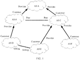
- FIG. 1 is a schematic diagram of an inter-AS routing and switching business relationship of the international internet.
- connections between ASs on the international internet are mainly classified into three types:
- P2P mutual access is usually free of charge.
- An S2S connection is usually used between different ASs of a same interest group (for example, a same carrier). The S2S connection is also free of charge.
- connection relationships are implemented by controlling a routing policy.
- a network administrator uses the routing policy to control route advertisement.
- a processing rule is as follows:
- the route leak is the same as a route prefix leak.
- the route prefix leak means a route including a route prefix is leaked.
- FIG. 2 is a schematic diagram of an application scenario according to an embodiment of the present invention.
- the application scenario includes an AS 100, an AS 11, an AS 12, an AS 13, an AS 21, an AS 22 and an AS 23.
- the AS 100 includes network nodes R1, R2, R3, R4, R5, and R6.
- R1, R3, R4, and R6 are border nodes of the AS 100, and R2 and R5 are internal nodes of the AS 100.
- a network monitoring device manages the AS 100.
- the network monitoring device may be a BGP monitoring (BGP Monitoring Protocol, BMP) server, a network management device, or a controller.
- BGP monitoring BGP Monitoring Protocol
- a management domain of the network monitoring device includes the AS 100.
- FIG. 2 shows only the AS 100, the management domain of the network monitoring device may include a plurality of ASs, for example, an AS 100, an AS 101, and an AS 102.
- the AS 100 is connected to a border node R11 of the AS 11 through R1.
- the AS 100 is connected to a border node R12 of the AS 12 through R1.
- the AS 100 is connected to a border node R21 of the AS 21 through R3.
- the AS 100 is connected to a border node R13 of the AS 13 through R4.
- the AS 100 is connected to the border node R21 of the AS 21 through R3.
- the AS 100 is connected to a border node R22 of the AS 22 through R6.
- the AS 100 is connected to a border node R23 of the AS 23 through R6.
- R1 establishes an external BGP (eBGP) peer relationship with R11.
- R1 establishes an eBGP peer relationship with R12.
- R4 establishes an eBGP peer relationship with R13.
- R3 establishes an eBGP peer relationship with R21.
- R6 establishes an eBGP peer relationship with R22.
- R6 establishes an eBGP peer relationship with R23.
- the AS 11, the AS 12, the AS 13, the AS 21, the AS 22, and the AS 23 are peer ASs of the AS 100.
- R1, R3, R4, and R6 separately establish a management channel connection with the network monitoring device.
- the network monitoring device obtains required information through the management channel connection.
- the management channel connection may be a TCP connection.
- R1, R3, R4, and R6 communicate with the network monitoring device over a border gateway protocol monitoring protocol (Border Gateway Protocol Monitoring Protocol, BMP).
- BMP Border Gateway Protocol Monitoring Protocol
- R1, R3, R4, and R6 send BGP running status information to the network monitoring device through a BMP packet.
- the network monitoring device parses and analyzes the received BMP packet.
- the border node and the internal node are network devices having a routing function, for example, may be routers or layer 3 switches.
- the border node R11 of the AS 11 advertises a piece of routing information A to the border node R1 of the AS 100, for example, may advertise the routing information A through a BGP update message (BGP update message).
- the routing information A includes a route prefix 10.1.0.0/16.
- the border node R12 of the AS 12 advertises a piece of routing information B to the border node R1 of the AS 100.
- the routing information B includes a route prefix 10.2.0.0/16.
- the border node R13 of the AS 13 advertises a piece of routing information C to the border node R4 of the AS 100.
- the routing information C includes a route prefix 10.3.0.0/16.
- R6 advertises the routing information A, the routing information B, and the routing information C to the border node R22 of the AS 22.
- R1 receives the route prefix 10.1.0.0/16 from the AS 11, and sends 10.1.0.0/16 to the AS 22.
- R1 receives the route prefix 10.2.0.0/16 from the AS 12, and sends 10.2.0.0/16 to the AS 22.
- R1 receives the route prefix 10.3.0.0/16 from the AS 13, and sends 10.3.0.0/16 to the AS 22.
- a transfer path of the route prefix 10.1.0.0/16 sequentially includes the AS 11, the AS 100, and the AS 22.
- a transfer path of the route prefix 10.2.0.0/16 sequentially includes the AS 12, the AS 100, and the AS 22.
- a transfer path of the route prefix 10.3.0.0/16 sequentially includes the AS 13, the AS 100, and the AS 22.
- a network administrator may configure an export ("export" is for a sending direction of a route) policy for each border node of the AS 100 according to the route leaking rule in FIG. 1 and based on an attribute of a business relationship between the AS 100 and other ASs shown in FIG. 2 .
- the export policy of R6 can be configured as: "If a route from the AS 12 is received, the route cannot be sent to the AS 22". This configuration does not cause a route leak. However, if the export policy of R6 is configured as: "If a route from the AS 12 is received, the route can be sent to the AS 22". This causes the route leak.
- R1 receives the route prefix 10.1.0.0/16 from the AS 11 and sends the route prefix 10.1.0.0/16 to the AS 22, the route leak does not occur. If R1 receives the route prefix 10.2.0.0/16 from the AS 12 and sends the route prefix 10.2.0.0/16 to the AS 22, the route leak occurs. If R4 receives the route prefix 10.3.0.0/16 from the AS 13 and sends the route prefix 10.3.0.0/16 to the AS 22, the route leak occurs.
- Embodiments of the present invention provide a method, device, and system for determining a route leak.
- the network management device receives an extended BMP message separately sent by an ingress border node (receiving a route prefix) and an egress border node (sending the route prefix) that are of an autonomous system managed by the network management device, to determine a receiving relationship and a sending relationship of the route prefix. Therefore, it can be determined whether the route prefix is leaked.
- the method, the device, and the system are based on a same inventive concept. Because problem-resolving principles of the method, the device, and the system are similar, mutual reference may be made between implementation of the device and implementation of the method, and mutual reference may also be made between implementation of the system and the implementation of the method. Repeated descriptions are omitted.
- a BMP session includes messages such as an initiation message (Initiation Message), a peer up notification (Peer Up Notification), a route monitoring (Router Monitoring) message, a peer down notification (Peer Down Notification), a state report (States Reports), and a termination message (Termination Message). These messages are sent in a form of packets.
- Reported information includes BGP routing information, BGP peer information, vendor information and a version number of a router, and the like.
- BMP message BMP message type Message description and function Initiation message
- a BMP protocol initiation message is used to notify a network monitoring device of vendor information, a version number, and the like
- Peer up notification Report establishment information about a BGP peer connection to a network monitoring device (Up) Route monitoring
- a route monitoring message is used to send all routes received from or sent to a peer to a network monitoring device, and report addition or withdrawal of routes to the network monitoring device at any time
- Peer down notification Report interruption of a BGP peer connection to a network monitoring device Down
- Termination message A termination message is used to notify a network monitoring device of a reason for closing a BMP session
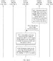
- FIG. 3A and FIG. 3B are a schematic flowchart of a method according to an embodiment of the present invention.
- an example is as follows.
- a network monitoring device in FIG. 3A and FIG. 3B may be the controller or the BMP server in FIG. 2 , and manages the AS 100.
- a first autonomous system in FIG. 3A and FIG. 3B may be the AS 100 in FIG. 2 .
- a second autonomous system in FIG. 3A and FIG. 3B may be the AS 11 in FIG. 2 .
- a third autonomous system in FIG. 3A and FIG. 3B may be the AS 22 in FIG. 2 .
- a first border node in FIG. 3A and FIG. 3B may be R1 in FIG. 2 .
- a second border node in FIG. 3A and FIG. 3B may be R6 in FIG. 2 .
- a first border node obtains a receiving relationship rule for receiving routing information that is from a second autonomous system.
- a network administrator may configure, on the first border node (R1) of the first autonomous system, the receiving relationship rule for R1 to receive the routing information from the second autonomous system (AS 22). Therefore, R1 may obtain the receiving relationship rule.
- the receiving relationship rule may be receiving based on a C2P relationship, receiving based on a P2P relationship, or receiving based on a P2C relationship.
- the receiving relationship rule may be configured based on a granularity of a peer autonomous system.
- peer autonomous systems corresponding to R1 are the AS 11 and the AS 12.
- R1 may be configured to receive all routing information from the AS 11 based on the C2P relationship, and to receive all routing information from the AS 12 based on the P2P relationship.
- the receiving relationship rule may be configured based on a granularity of a route prefix.
- R1 may be configured to receive a route prefix x.x.0.0/16 from the AS 11 based on the C2P relationship and a route prefix x.y.0.0/16 from the AS 11 based on the P2C relationship.
- x and y herein indicate any valid numbers that comply with a route prefix coding rule.
- configuration of the granularity of the route prefix and configuration of the granularity of the peer autonomous system may coexist.
- the configuration of the granularity of the route prefix has a higher priority.
- two rules of the granularity of the route prefix may be configured for the routing information sent from the AS 11.
- R1 receives the route prefix x.x.0.0/16 from the AS 11 based on the C2P relationship.
- R1 receives the route prefix x.y.0.0/16 from the AS 11 based on the P2C relationship.
- a rule of the granularity of the peer autonomous system is configured, and R1 receives the route prefix from the AS 11 based on the C2P relationship.
- a second border node obtains a sending relationship rule for sending routing information to a third autonomous system.
- the second border node (R6) obtains the sending relationship rule for sending the routing information to the third autonomous system (AS 22).
- the sending relationship rule may be sending based on the C2P relationship, sending based on the P2P relationship, or sending based on the P2C relationship.
- the first border node receives routing information that is sent by the second autonomous system and that includes a route prefix 10.1.0.0/16.
- the border node R11 of the AS 22 advertises the routing information including the route prefix 10.1.0.0/16 through a BGP update message (BGP update message). Therefore, R1 receives the routing information.
- the first border node generates a first extended BMP route monitoring (BMP Route Monitoring) packet, where the first extended BMP route monitoring packet carries a receiving relationship of the route prefix that has been received by the first border node from the second autonomous system.
- the receiving relationship of the route prefix is a business relationship between a sender AS of the route prefix and a receiver AS of the route prefix when a border node of the receiver AS receives the route prefix.
- information carried in the packet indicates that "the receiving relationship of the route prefix 10.1.0.0/16 received by R1 from the AS 11 is C2P", to be specific, when the route prefix 10.1.0.0/16 is received by R1, as the receiver, a business relationship identity of the AS 100 on which R1 is located is a provider (Provider), and as the sender of 10.1.0.0/16, a business relationship identity of the AS 11 is a customer (Customer).
- R1 determines the receiving relationship of 10.1.0.0/16 according to the receiving relationship rule obtained in the step S301.
- the receiving relationship rule is of the granularity of the peer autonomous system, and content is receiving based on the C2P relationship, the receiving relationship of 10.1.0.0/16 is determined as C2P. If the receiving relationship rule is of both the granularity of the route prefix and the granularity of the peer autonomous system, the granularity of the route prefix has a higher priority.
- R1 sends a BMP route monitoring packet to the network monitoring device after S303 is performed.
- the packet includes a common header (Common Header), a per-peer header (Per-Peer Header), and a BGP update protocol date unit (BGP Update Protocol Date Unit, BGP Update PDU).
- the BMP route monitoring packet in the existing protocol is extended, and is referred to as the extended BMP route monitoring packet. Therefore the BMP route monitoring packet may carry the information that "the receiving relationship of the route prefix 10.1.0.0/16 received by R1 from the AS 11 is C2P".
- a peer AS (Peer AS) field included in the per-peer header carries information about the second autonomous system.
- An 'O' bit in the per-peer header is used to indicate "receiving" or "sending”.
- a BGP update PDU in the per-peer header carries the received route prefix, and an extended field carries the receiving relationship.
- the peer AS field in the per-peer header carries information about the AS 22.
- the 'O' bit in the per-peer header indicates "receiving".
- the BGP update PDU in the per-peer header carries 10.1.0.0/16.
- the extended field may carry the receiving relationship in a type-length-value (Type-Length-Value) manner.
- a possible manner is as follows: A value of a type field being 1 indicates a relationship between a route prefix source AS and a local AS, a value of a value field being 1 indicates C2P, the value of the value field being 2 indicates P2P, and the value of the value field being 3 indicates P2C.
- the value of the type field is 1, and the value of the value field is 1.
- the value of the type field being 3 indicates information about a relationship between ASs, and a format of the value field may be (a sender AS, a receiver AS, a business relationship). Values 1, 2, and 3 of the business relationship indicate C2P, P2P, and P2C respectively. Specifically, in this example, the value of the type field is 3, and the value of the value field is (information about the AS 11, information about the AS 100, 1).
- the value of the type field is 1, 2, or 3.
- the value of the value field is 1, 2, or 3. This is merely an example, and may also be another value. This is not limited herein.
- the foregoing provides several manners in which the BMP route monitoring packet is extended in the existing protocol, so that the BMP route monitoring packet can carry the information that "the receiving relationship of the route prefix 10.1.0.0/16 received by R1 from the AS 11 is C2P". It should be understood that another extension manner may also be used to achieve a same objective.
- the first border node sends the first extended BMP route monitoring packet to a network monitoring device.
- the network monitoring device receives the first extended BMP route monitoring packet.
- the second border node sends the routing information including the route prefix 10.1.0.0/16 to the third autonomous system.
- the routing information including the route prefix 10.1.0.0/16 is transferred to the second border node R6 through internal nodes of the AS 100. Then, R6 advertises the routing information including the route prefix 10.1.0.0/16 to the third autonomous system (AS 22) through the BGP update message.
- the second border node generates a second extended BMP route monitoring packet, where the second extended BMP route monitoring packet carries a sending relationship of the route prefix that has been sent by the second border node to the third autonomous system.
- the sending relationship of the route prefix is a business relationship between a sender AS of the route prefix and a receiver AS of the route prefix when a border node of the sender AS of the route prefix sends the route prefix to the receiver AS.
- information carried in the packet indicates that "the sending relationship of the route prefix 10.1.0.0/16 sent by R6 to the AS 22 is P2P", to be specific, when the border node R6 of the AS 100 sends the route prefix 10.1.0.0/16 to the AS 22, as the sender, the business relationship identity of the AS 100 is a peer (Peer), and as the receiver, a business relationship identity of the AS 22 is a peer (peer).
- R6 For how R6 generates the second extended BMP route monitoring packet, refer to the description in the extended field in S304.
- the value of the type field is 2, and the value of the value field is 2.
- the value of the type field is 1, 2, or 3.
- the value of the value field is 1, 2, or 3. This is merely an example, and may also be another value. This is not limited herein.
- the second border node sends the second extended BMP route monitoring packet to the network monitoring device.
- the network monitoring device receives the second extended BMP route monitoring packet.
- the network monitoring device determines, based on the receiving relationship carried in the received first extended BMP route monitoring packet and the sending relationship carried in the received second extended BMP route monitoring packet, that the receiving relationship of the route prefix 10.1.0.0/16 received by R1 from the AS 11 is C2P, and the sending relationship of the route prefix 10.1.0.0/16 sent by R6 to the AS 22 is P2P.
- the network monitoring device may determine the information.
- the network monitoring device determines, based on the determined receiving relationship and the determined sending relationship, whether the route prefix is leaked.
- the network monitoring device may determine, according to the following route leak determining rule, whether the route prefix is leaked:
- the receiving relationship is the peer-to-peer relationship, and the sending relationship is the peer-to-peer relationship, it is determined that the route prefix is leaked; or if the receiving relationship is the peer-to-peer relationship, and the sending relationship is the client-to-provider relationship, it is determined that the route prefix is leaked; or if the receiving relationship is the provider-to-client relationship, and the sending relationship is the peer-to-peer relationship, it is determined that the route prefix is leaked; or if the receiving relationship is the provider-to-client relationship, and the sending relationship is the client-to-provider relationship, it is determined that the route prefix is leaked.
- the receiving relationship of the route prefix 10.1.0.0/16 is C2P, and the sending relationship is P2P. Therefore, the route prefix 10.1.0.0/16 is not leaked.
- the network monitoring device associates information of the first extended BMP route monitoring packet and the second extended BMP route monitoring packet based on that the two packets include a same route prefix 10.1.0.0/16.
- the network monitoring device determines, based on an extended BMP route monitoring packet sent by each border node of the AS 100, whether a route leak occurs in the AS 100.
- Table 2 shows an example in which route prefixes are sent by R6 to the AS 22, and the network monitoring device determines whether the route leak occurs in the AS 100 and which route prefixes are leaked.
- Table 2 Network monitoring device determines whether a route prefix sent from R6 to an AS 22 is leaked Route prefix Receiving relationship Sending relationship Source AS Local AS Destination AS Leaked or not leaked 10.1.0.0/16 C2P P2P AS 11 AS 100 AS 22 No 10.2.0.0/16 P2P P2P AS 12 AS 100 AS 22 Yes 10.3.0.0/16 P2C P2P AS 13 AS 100 AS 22 Yes
- the network monitoring device may learn, in a plurality of manners, that the AS 100 is the local AS in Table 1. For example, after R1 establishes an eBGP peer relationship with R11, R1 sends a BMP peer up notification (Peer Up Notification) packet to the network monitoring device according to the BMP protocol.
- the BMP peer up notification packet carries the information about the local AS (AS 100) and the information about the peer AS (AS 11). Therefore, the network monitoring device learns that R1 is a border node of the AS 100.
- the network monitoring device may determine, through analysis, that the AS 100 receives the route prefix 10.1.0.0/16.
- the network monitoring device may also learn that 10.1.0.0/16 is sent by the AS 11 to the AS 100. In this way, with reference to the second extended BMP route monitoring packet sent by R6, it may be learned that 10.1.0.0/16 is sent by the AS 100 to the AS 22. Therefore, the network monitoring device combines, according to 10.1.0.0/16, information in the first extended BMP route monitoring packet and information in the second extended BMP route monitoring packet, and may obtain 10.1.0.0/16 through analysis.
- an action of R1 may be independent of an action of R6, and R6 may not be performed later than R1.
- a sequence of S306 may interchange with a sequence of S307.
- the receiving relationship and the sending relationship are carried by extending the BMP route monitoring packet.
- the network monitoring device may directly obtain the receiving relationship and the sending relationship of 10.1.0.0/16 from the extended BMP route monitoring packet. There is no need to analyze the BMP peer up notification packet to determine whether 10.1.0.0/16 is leaked.
- FIG. 4A-1 and FIG. 4A-2 are a schematic flowchart of a method according to an embodiment of the present invention.
- an example in FIG. 4A-1 and FIG. 4A-2 is similar to that in the embodiment in FIG. 3A and FIG. 3B .
- a BMP peer up notification packet is extended.
- R1 carries, in a BMP peer up notification packet sent to a network monitoring device, the receiving relationship rule described in the embodiment in FIG. 3A and FIG. 3B .
- R6 carries, in a BMP peer up notification packet sent to the network monitoring device, the receiving relationship rule described in the embodiment in FIG. 3A and FIG. 3B .
- the network monitoring device may combine information in the three packets.
- the network monitoring device determines that a receiving relationship of the route prefix 10.1.0.0/16 received by R1 from the AS 11 is C2P, and that a sending relationship of the route prefix 10.1.0.0/16 sent by R6 to the AS 22 is P2P, to determine whether a route leak occurs.
- a first border node obtains a receiving relationship rule for receiving routing information from a second autonomous system.
- the first border node generates a first extended BMP peer up notification packet, where the first extended BMP peer up notification packet carries the receiving relationship rule obtained in S401.
- the receiving relationship rule is that "all routing information received by R1 from the AS 11 is received based on the C2P relationship". Because the peer up notification packet includes a common header (Common Header) and a per-peer header (Per-Peer Header), in a possible manner, the same manner in S304 may be used. In an extended field, the receiving relationship rule may be carried in a type-length-value manner.
- the first border node sends the first extended BMP peer up notification packet to a network monitoring device, and the network monitoring device receives the first extended BMP peer up notification packet.
- a second border node obtains a sending relationship rule for sending routing information to a third autonomous system.
- S405 The second border node generates a second extended BMP peer up notification packet, where the second extended BMP peer up notification packet carries the sending relationship rule obtained in S402. Refer to the packet extension manner in S307.
- the second border node sends the second extended BMP peer up notification packet to the network monitoring device, and the network monitoring device receives the second extended BMP peer up notification packet.
- the second border node sends routing information including a route prefix 10.1.0.0/16 to the third autonomous system.
- S408 The second border node generates a BMP route monitoring packet.
- R6 After S407 is performed, R6 generates the BMP route monitoring packet according to the existing BMP protocol.
- the BMP route monitoring packet includes BGP routing information sent by R6 to the AS 22. Refer to an example in Table 3. Table 3 BGP routing information sent by R6 to an AS 22: Prefix AS path 10.1.0.0/16 AS-path: 100 11 10.2.0.0/16 AS-path: 100 12 10.3.0.0/16 AS-path: 100 13
- Table 3 shows that a BGP route sent by R6 to the AS 22 sequentially passes through the AS 11 and the AS 100.
- Information about the AS 22 may be carried in a peer AS field in a per-peer header of the BMP route monitoring packet. Therefore, the BMP route monitoring packet generated by R6 may indicate that the transmission path of the route prefix 10.1.0.0/16 sequentially includes the AS 11, the AS 100, and the AS 22.
- the second border node sends the BMP route monitoring packet to the network monitoring device.
- the network monitoring device receives the BMP route monitoring packet sent by the second border node.
- the network monitoring device may determine, according to the receiving relationship rule ("R1 receives the route prefix 10.1.0.0/16 from the AS 11 based on a C2P relationship”) carried in the received first extended BMP peer up notification packet, the sending relationship rule ("R6 sends the route prefix 10.1.0.0/16 to the AS 22 based on a P2P relationship”) carried in the received second extended BMP peer up notification packet, and a transfer path of the route prefix ("The transfer path of the route prefix 10.1.0.0/16 sequentially includes the AS 11, an AS 100, and the AS 22”) carried in the received BMP route monitoring packet, that a receiving relationship of the route prefix 10.1.0.0/16 received by R1 from the AS 11 is C2P, and a sending relationship of the route prefix 10.1.0.0/16 sent by R6 to the AS 22 is P2P, namely, the receiving relationship and the sending relationship mentioned in S304 and S307. It may be understood that when the network monitoring device determines the receiving relationship and the sending relationship, the network monitoring device knows that R1 and R1 and
- S411 The network monitoring device determines, based on the determined receiving relationship and the determined sending relationship, whether the route prefix is leaked. For details, refer to S310.
- an action of R1 may be independent of an action of R6, and R6 may not be performed later than R1.
- a sequence of S407 may interchange with a sequence of S408.
- the BMP peer up notification packet may be extended to carry the receiving relationship rule and the sending relationship rule, it may be avoided to carry the receiving relationship and the sending relationship in each BMP route monitoring packet. Because the BMP peer up notification packet is sent once when a BGP peer relationship is established, and the BMP route monitoring packet is triggered each time a border node receives or sends routing information. The embodiment in FIG. 4A-1 and FIG. 4A-2 can reduce repeated carrying of business relationship information.
- the network monitoring device may monitor only a BMP route monitoring packet sent by an egress border node. This reduces monitoring workload.
- FIG. 4B-1 and FIG. 4B-2 are a schematic flowchart of a method according to an embodiment of the present invention.
- the receiving relationship rule and the sending relationship rule are carried by extending the BMP peer up notification packet.
- the network monitoring device determines, based on the first extended BMP peer up notification packet and a first BMP route monitoring packet that are sent by R1, and the second extended BMP peer up notification packet and a first BMP route monitoring packet that are sent by R6, the receiving relationship and the sending relationship of the route prefix.
- the network monitoring device can also determine whether the route prefix is leaked without depending on transmission path information of a BMP route monitoring packet of an AS.
- the network monitoring device after determining that the route leak occurs in the route prefix, the network monitoring device outputs alarm information.
- the alarm information indicates that the route prefix is leaked from the first autonomous system to the third autonomous system.
- the network monitoring device outputs alarm information.
- the alarm information indicates that the route prefixes 10.2.0.0/16 and 10.3.0.0/16 are leaked from the AS 100 to the AS 22. In this way, the network administrator can promptly check import policies and export policies of both R1 and R6, to find faulty policy configuration.
- FIG. 5 is a possible schematic structural diagram of a network monitoring device related in the foregoing method embodiments.
- the network monitoring device 500 may implement functions of the network monitoring device in the embodiments shown in FIG. 3A and FIG. 3B , FIG. 4A-1 and FIG. 4A-2 , or FIG. 4B-1 and FIG. 4B-2 .
- the network monitoring device 500 includes a receiving unit 501 and a determining unit 502. These units may perform corresponding functions of the network monitoring device in the foregoing method embodiments.
- the receiving unit 501 is configured to support the network monitoring device 500 in performing S305, S308, S403, and S406 in the processes in FIG. 3A and FIG. 3B , FIG. 4A-1 and FIG. 4A-2 , and FIG.
- the determining unit 502 is configured to support the network monitoring device 500 in performing S309, S301, S410, S411, S413, and S414 in FIG. 3A and FIG. 3B , FIG. 4A-1 and FIG. 4A-2 , and FIG. 4B-1 and FIG. 4B-2 .
- S309, S301, S410, S411, S413, and S414 in FIG. 3A and FIG. 3B , FIG. 4A-1 and FIG. 4A-2 , and FIG. 4B-1 and FIG. 4B-2 For a specific execution process, refer to the detailed descriptions of corresponding steps in the foregoing embodiments shown in FIG.3 , FIG. 4A-1 and FIG. 4A-2 , and FIG. 4B-1 and FIG. 4B-2 . Details are not described herein again.
- the network monitoring device 500 may further include a sending unit, configured to output alarm information after the network monitoring device 500 determines that a route leak occurs in a route prefix.
- the alarm information indicates that the route prefix is leaked from a first autonomous system to a third autonomous system.
- FIG. 6 is a possible schematic structural diagram of a network monitoring device 600 related in the foregoing method embodiments.
- the network monitoring device 600 includes a processor 601, a memory 602, a communications interface 603, and a bus 604.
- the processor 601, the communications interface 603, and the memory 602 are connected to each other through the bus 604.
- the bus 604 may be a peripheral component interconnect (peripheral component interconnect, PCI for short) bus, an extended industry standard architecture (extended industry standard architecture, EISA for short) bus, or the like.
- PCI peripheral component interconnect
- EISA extended industry standard architecture
- the bus may be classified into an address bus, a data bus, a control bus, and the like. For ease of representation, only one thick line is used to represent the bus in FIG.
- the network monitoring device 600 may implement functions of the network monitoring device in the embodiments shown in FIG. 3A and FIG. 3B , FIG. 4A-1 and FIG. 4A-2 , or FIG. 4B-1 and FIG. 4B-2 .
- the communications interface 603 is configured to support performing S305, S308, S403 and S406 in the processes in FIG. 3A and FIG. 3B , FIG. 4A-1 and FIG. 4A-2 , and FIG. 4B-1 and FIG. 4B-2 , S409 in FIG. 4A-1 and FIG. 4A-2 , and 409 and S412 in FIG. 4B-1 and FIG. 4B-2 .
- the processor 601 is configured to store a computer program.
- the computer program includes a program instruction.
- the processor 601 is configured to invoke the program instruction to perform S309, S301, S410, S411, S413, and S414 in FIG. 3A and FIG. 3B , FIG. 4A-1 and FIG. 4A-2 , and FIG. 4B-1 and FIG. 4B-2 .
- the communications interface 603 is further configured to output alarm information after determining that a route leak occurs in a route prefix. The alarm information indicates that the route prefix is leaked from a first autonomous system to a third autonomous system.
- FIG. 7 is a possible schematic structural diagram of a first border node related in the embodiment in FIG. 3A and FIG. 3B .
- the first border node may be a routing device 700, and the routing device 700 includes a determining unit 701, a generation unit 702, and a sending unit 703.
- the determining unit 701 may perform a determining action in S304 in FIG. 3A and FIG. 3B .
- the determining action in S304 determines the receiving relationship according to the receiving relationship rule.
- the generation unit 702 may perform a generation action in S304 in FIG. 3A and FIG. 3B .
- the sending unit 703 may perform S305 in FIG. 3A and FIG. 3B .
- the routing device 700 may further include an obtaining unit and a receiving unit. The obtaining unit performs S301, and the receiving unit performs S303.
- FIG. 8 is a possible schematic structural diagram of a first border node related in the embodiment in FIG. 3A and FIG. 3B .
- the first border node may be a routing device 800, and the routing device 800 includes a processor 801, a memory 802, a communications interface 803, and a bus 804. A structure thereof is similar to that in the embodiment in FIG. 6 .
- the communications interface 803 is configured to perform S305.
- the communications interface 803 may further perform S301 and S303.
- the processor 801 is configured to store a computer program.
- the computer program includes a program instruction.
- the processor 801 is configured to invoke the program instruction to perform S304. For example, a determining action in S304 determines the receiving relationship according to the receiving relationship rule.
- FIG. 9 is a possible schematic structural diagram of a first border node related in the embodiments shown in FIG. 4A-1 and FIG. 4A-2 and FIG. 4B-1 and FIG. 4B-2 .
- the first border node may be a routing device 900, and the routing device 900 includes an obtaining unit 901, a generation unit 902, and a sending unit 903.
- the obtaining unit 901 performs S401 in FIG. 4A-1 and FIG. 4A-2 and FIG. 4B-1 and FIG. 4B-2 .
- the generation unit 902 performs S402 in FIG. 4A-1 and FIG. 4A-2 and FIG. 4B-1 and FIG. 4B-2 .
- the sending unit 903 performs S403 in FIG. 4A-1 and FIG. 4A-2 and FIG. 4B-1 and FIG.
- a receiving unit is further included.
- the receiving unit performs S407 in FIG. 4B-1 and FIG. 4B-2 .
- the generation unit 902 further performs S408 in FIG. 4B-1 and FIG. 4B-2 .
- the sending unit 903 further performs S409 in FIG. 4B-1 and FIG. 4B-2 .
- FIG. 10 is a possible schematic structural diagram of a first border node related in the embodiments shown in FIG. 4A-1 and FIG. 4A-2 and FIG. 4B-1 and FIG. 4B-2 .
- the first border node may be a routing device 1000, and the routing device 1000 includes a processor 1001, a memory 1002, a communications interface 1003, and a bus 1004. A structure thereof is similar to that in the embodiment in FIG. 6 .
- the communications interface 1003 performs S401 and S403 in FIG. 4A-1 and FIG. 4A-2 and FIG. 4B-1 and FIG. 4B-2 .
- the processor 1001 is configured to store a computer program.
- the computer program includes a program instruction.
- the processor 1001 is configured to invoke the program instruction to perform S402 in FIG. 4A-1 and FIG.
- the communications interface 1003 may further perform S407 and S409 in FIG. 4B-1 and FIG. 4B-2 .
- the processor 1001 is further configured to invoke the program instruction to perform S408 in FIG. 4B-1 and FIG. 4B-2 .
- FIG. 11 is a possible schematic structural diagram of a second border node related in the embodiment in FIG. 3A and FIG. 3B .
- the second border node may be a routing device 1100, and the routing device 1100 includes a determining unit 1101, a generation unit 1102, and a sending unit 1103.
- the determining unit 1101 performs S307.
- a determining action in S304 determines the sending relationship according to the sending relationship rule.
- the generation unit 1102 performs S307.
- the sending unit 1103 performs S308.
- the routing device 1100 may further include an obtaining unit and a sending unit.
- the obtaining unit performs S302, and the sending unit performs S306.
- FIG. 12 is a possible schematic structural diagram of a second border node related in the embodiment in FIG. 3A and FIG. 3B .
- the second border node may be a routing device 1200, and the routing device 1200 includes a processor 1201, a memory 1202, a communications interface 1203, and a bus 1204. A structure thereof is similar to that in the embodiment in FIG. 6 .
- the communications interface 1203 is configured to perform S308.
- the processor 1201 is configured to store a computer program.
- the computer program includes a program instruction.
- the processor 1201 is configured to invoke the program instruction to perform S307. For example, a determining action in S307 determines the receiving relationship according to the receiving relationship rule.
- the communications interface 1203 is further configured to perform S302 and S306.
- FIG. 13 is a possible schematic structural diagram of a second border node related in the embodiments shown in FIG. 4A-1 and FIG. 4A-2 and FIG. 4B-1 and FIG. 4B-2 .
- the second border node may be a routing device 1300, and the routing device 1300 includes an obtaining unit 1301, a generation unit 1302, and a sending unit 1303.
- the obtaining unit performs S404 in FIG. 4A-1 and FIG. 4A-2 or S405 in FIG. 4B-1 and FIG. 4B-2 .
- the generation unit 1302 performs S405 and S408 in FIG. 4A-1 and FIG. 4A-2 , or S405 and S411 in FIG. 4B-1 and FIG. 4B-2 .
- the sending unit 1303 performs S406, S407, and S409 in FIG. 4A-1 and FIG. 4A-2 , or S406, S410, and S412 in FIG. 4B-1 and FIG. 4B-2 .
- FIG. 14 is a possible schematic structural diagram of a second border node related in the embodiments shown in FIG. 4A-1 and FIG. 4A-2 and FIG. 4B-1 and FIG. 4B-2 .
- the second border node may be a routing device 1400, and the routing device 1400 includes a processor 1401, a memory 1402, a communications interface 1403, and a bus 1404. A structure thereof is similar to that in the embodiment in FIG. 6 .
- the communications interface 1403 is configured to perform S404, S406, S407, and S409 in FIG. 4A-1 and FIG. 4A-2 , or S405, S406, S410, and S412 in FIG. 4B-1 and FIG. 4B-2 .
- the processor 1401 is configured to store a computer program.
- the computer program includes a program instruction.
- the processor 1401 is configured to invoke the program instruction to perform S405 and S408 in FIG. 4A-1 and FIG. 4A-2 , or S405 and S411 in FIG. 4B-1 and FIG. 4B-2 .
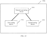
- FIG. 15 provides a system 1500 for determining a route leak.
- the system 1500 is configured to implement the method for determining a route leak in the foregoing method embodiments.
- the system 1500 includes a network monitoring device 1501, a first routing device 1502, and a second network device 1503.
- the network monitoring device 1501, the first routing device 1502, and the second network device 1503 may respectively implement functions of the network monitoring device, the first border node, and the second border node in the embodiments shown in FIG. 3A and FIG. 3B , FIG. 4A-1 and FIG. 4A-2 , or FIG. 4B-1 and FIG. 4B-2 .
- the first monitoring device 1501 may be the monitoring device in the embodiment in FIG. 5 or FIG. 6 .
- the first routing device 1502 may be the routing device in the embodiments shown in FIG. 7 to FIG. 10 .
- the first routing device 1503 may be the routing device in the embodiments shown in FIG. 11 to FIG. 14 .
- An embodiment of the present invention further provides a storage medium.
- the computer-readable storage medium stores a program.
- a computer is enabled to perform the method in the foregoing method embodiments.
- units in the foregoing device embodiments may be integrated.
- the determining unit 701 and the generation unit 702 in the embodiment in FIG. 7 may be combined into one unit.
- the obtaining unit, the receiving unit, and the sending unit in the embodiment in FIG. 9 may be combined into one unit.
- any apparatus embodiment described above is merely an example.
- the units described as separate parts may or may not be physically separate, and parts displayed as units may or may not be physical units, may be located in one position, or may be distributed on a plurality of network units. Some or all the modules may be selected according to actual needs to achieve the objectives of the solutions of the embodiments.
- connection relationships between modules indicate that the modules have communication connections with each other, which may be specifically implemented as one or more communications buses or signal cables. Persons of ordinary skill in the art may understand and implement the embodiments of the present invention without creative efforts.
- the software instruction may include a corresponding software module.
- the software module may be stored in a random access memory (random access memory, RAM), a flash memory, a read-only memory (read only memory, ROM), an erasable programmable read-only memory (erasable programmable ROM, EPROM), an electrically erasable programmable read-only memory (Electrically EPROM, EEPROM), a hard disk, a removable hard disk, a compact disc, or any other form of storage medium well-known in the art.
- a storage medium is coupled to a processor, so that the processor can read information from the storage medium or write information into the storage medium.
- the storage medium may be a component of the processor.
- the processor and the storage medium may be located in an ASIC.
- the computer-readable medium includes a computer storage medium and a communications medium, where the communications medium includes any medium that enables a computer program to be transmitted from one place to another.
- the storage medium may be any available medium accessible to a general-purpose or special-purpose computer.
Landscapes
- Engineering & Computer Science (AREA)
- Computer Networks & Wireless Communication (AREA)
- Signal Processing (AREA)
- Computer Security & Cryptography (AREA)
- Computer Hardware Design (AREA)
- Computing Systems (AREA)
- General Engineering & Computer Science (AREA)
- Data Exchanges In Wide-Area Networks (AREA)
Applications Claiming Priority (2)
| Application Number | Priority Date | Filing Date | Title |
|---|---|---|---|
| CN201811158313.4A CN110971522B (zh) | 2018-09-30 | 2018-09-30 | 一种确定路由泄露的方法、设备和系统 |
| PCT/CN2019/106072 WO2020063392A1 (zh) | 2018-09-30 | 2019-09-17 | 一种确定路由泄露的方法、设备和系统 |
Publications (3)
| Publication Number | Publication Date |
|---|---|
| EP3852328A1 true EP3852328A1 (de) | 2021-07-21 |
| EP3852328A4 EP3852328A4 (de) | 2021-08-25 |
| EP3852328B1 EP3852328B1 (de) | 2023-11-08 |
Family
ID=69951194
Family Applications (1)
| Application Number | Title | Priority Date | Filing Date |
|---|---|---|---|
| EP19864222.5A Active EP3852328B1 (de) | 2018-09-30 | 2019-09-17 | Verfahren, vorrichtung und system zur bestimmung eines leitungslecks |
Country Status (4)
| Country | Link |
|---|---|
| US (1) | US11799774B2 (de) |
| EP (1) | EP3852328B1 (de) |
| CN (1) | CN110971522B (de) |
| WO (1) | WO2020063392A1 (de) |
Cited By (1)
| Publication number | Priority date | Publication date | Assignee | Title |
|---|---|---|---|---|
| WO2022150855A1 (en) * | 2021-01-11 | 2022-07-14 | Cisco Technology, Inc. | Detecting communication pathways affected by session flaps |
Families Citing this family (7)
| Publication number | Priority date | Publication date | Assignee | Title |
|---|---|---|---|---|
| CN113132228A (zh) * | 2019-12-31 | 2021-07-16 | 华为技术有限公司 | 一种路径校验方法及相关设备 |
| CN113572685B (zh) * | 2020-04-29 | 2023-03-10 | 华为技术有限公司 | 一种信息上报方法、信息处理方法、装置及设备 |
| CN114095428A (zh) * | 2020-07-21 | 2022-02-25 | 华为技术有限公司 | 一种路由管理方法、装置及系统 |
| CN112887208B (zh) * | 2021-01-27 | 2022-03-22 | 北京邮电大学 | 一种路由泄露检测方法、装置及设备 |
| CN112995183A (zh) * | 2021-03-05 | 2021-06-18 | 清华大学 | 一种互联网路由信息泄漏检测方法 |
| CN114244734B (zh) * | 2021-11-19 | 2024-02-09 | 新华三技术有限公司合肥分公司 | 报文发送方法及装置 |
| CN116112418B (zh) * | 2023-01-17 | 2025-10-17 | 清华大学 | 路由泄露的定位方法、装置、电子设备及存储介质 |
Family Cites Families (23)
| Publication number | Priority date | Publication date | Assignee | Title |
|---|---|---|---|---|
| CN101005500A (zh) * | 2006-12-31 | 2007-07-25 | 中国科学院计算技术研究所 | 一种基于自治系统关系的边界网关协议路由策略验证方法 |
| CN101252488B (zh) * | 2008-04-15 | 2012-07-04 | 中国科学院计算技术研究所 | 一种多自治系统路由器级拓扑处理系统和方法 |
| CN101588343A (zh) * | 2008-05-20 | 2009-11-25 | 中国人民解放军信息工程大学 | 前缀与as映射关系的管理方法、报文处理方法和装置 |
| CN102104550B (zh) * | 2011-03-10 | 2012-07-04 | 中国人民解放军信息工程大学 | 域间路由系统中自治系统间信任关系的建立和维护方法 |
| CN102148832B (zh) * | 2011-04-07 | 2013-06-12 | 清华大学 | 边界网关路由协议路径鉴定方法 |
| US20140129735A1 (en) * | 2011-06-23 | 2014-05-08 | Telefonaktiebolaget L M Ericsson (Publ) | Method and node for supporting routing via inter as path |
| US8675664B1 (en) * | 2011-08-03 | 2014-03-18 | Juniper Networks, Inc. | Performing scalable L2 wholesale services in computer networks using customer VLAN-based forwarding and filtering |
| CN102394794A (zh) * | 2011-11-04 | 2012-03-28 | 中国人民解放军国防科学技术大学 | 防范边界网关协议路由劫持的协同监测方法 |
| CN103236978B (zh) * | 2013-04-17 | 2016-03-23 | 清华大学 | As拓扑顶层自治系统结点的确定方法和装置 |
| US9826025B2 (en) * | 2013-05-21 | 2017-11-21 | Cisco Technology, Inc. | Chaining service zones by way of route re-origination |
| CN109246008B (zh) * | 2014-07-23 | 2021-08-20 | 华为技术有限公司 | 网络设备、系统和发送bgp信息的方法 |
| GB2537338A (en) * | 2014-11-28 | 2016-10-19 | Aria Networks Ltd | Modeling a border gateway protocol network |
| CN105991567B (zh) * | 2015-02-06 | 2020-07-31 | 南京中兴软件有限责任公司 | 发送处理方法及装置 |
| US10097449B2 (en) * | 2015-02-20 | 2018-10-09 | Cisco Technology, Inc. | Optimized border gateway protocol best path selection for optimal route reflection |
| CN112291145B (zh) * | 2015-07-06 | 2024-05-14 | 华为技术有限公司 | 路由控制的方法、设备和系统 |
| CN106487709A (zh) * | 2015-08-28 | 2017-03-08 | 中兴通讯股份有限公司 | 一种报文发送方法及系统 |
| CN106713162B (zh) * | 2015-11-17 | 2020-01-21 | 中国移动通信集团公司 | 统计bgp团体属性或扩展团体属性流量值的方法及装置 |
| CN106982162B (zh) * | 2016-01-19 | 2020-02-21 | 华为技术有限公司 | 用于转发业务流的方法、装置和系统 |
| CN106060014B (zh) * | 2016-05-18 | 2019-04-26 | 中国互联网络信息中心 | 一种同时解决前缀劫持、路径劫持及路由泄露攻击的方法 |
| CN106059916B (zh) * | 2016-05-31 | 2020-10-13 | 新华三技术有限公司 | 一种路由注入方法及装置 |
| CN106161256B (zh) * | 2016-07-26 | 2019-08-23 | 新华三技术有限公司 | 一种边界网关协议bgp路由的处理方法及装置 |
| CN108134707B (zh) * | 2016-12-01 | 2021-08-03 | 华为技术有限公司 | 一种路由检测的方法、系统及网络设备 |
| US10277499B2 (en) * | 2017-02-07 | 2019-04-30 | Level 3 Communications, Llc | System and method for next hop BGP routing in a network |
-
2018
- 2018-09-30 CN CN201811158313.4A patent/CN110971522B/zh active Active
-
2019
- 2019-09-17 EP EP19864222.5A patent/EP3852328B1/de active Active
- 2019-09-17 WO PCT/CN2019/106072 patent/WO2020063392A1/zh not_active Ceased
-
2021
- 2021-03-29 US US17/215,710 patent/US11799774B2/en active Active
Cited By (1)
| Publication number | Priority date | Publication date | Assignee | Title |
|---|---|---|---|---|
| WO2022150855A1 (en) * | 2021-01-11 | 2022-07-14 | Cisco Technology, Inc. | Detecting communication pathways affected by session flaps |
Also Published As
| Publication number | Publication date |
|---|---|
| US11799774B2 (en) | 2023-10-24 |
| WO2020063392A1 (zh) | 2020-04-02 |
| CN110971522A (zh) | 2020-04-07 |
| EP3852328A4 (de) | 2021-08-25 |
| CN110971522B (zh) | 2021-09-17 |
| EP3852328B1 (de) | 2023-11-08 |
| US20210234797A1 (en) | 2021-07-29 |
Similar Documents
| Publication | Publication Date | Title |
|---|---|---|
| EP3852328A1 (de) | Verfahren, vorrichtung und system zur bestimmung eines leitungslecks | |
| US10972391B2 (en) | Full-path validation in segment routing | |
| Coltun | The OSPF opaque LSA option | |
| KR102620025B1 (ko) | 경로 처리 방법 및 네트워크 장치 | |
| CN107251509B (zh) | 通信网络系统之间的可信路由 | |
| US7471669B1 (en) | Routing of protocol data units within a communication network | |
| CN101699786B (zh) | 一种丢包检测的方法、装置和系统 | |
| CN113347091A (zh) | 灵活算法感知边界网关协议前缀分段路由标识符 | |
| US7707308B1 (en) | OSPF routing to geographically diverse applications using OSPF and route health injection (RHI) | |
| CN116782336B (zh) | 一种通信方法及装置 | |
| US8995667B2 (en) | Mechanism for co-ordinated authentication key transition for IS-IS protocol | |
| US12316541B2 (en) | Exit interface selection based on intermediate paths | |
| US20240214802A1 (en) | Wireless client group isolation within a network | |
| US9282025B2 (en) | Medium access control address protection method and switch | |
| US10419336B2 (en) | Using disaggregated route information bases (“RIBS”) to increase the resiliency of protocols such as the border gateway protocol (“BGP”) | |
| EP1185041B1 (de) | Autonomes OSPF-System mit einem in zwei Teilbereichen getrennten Haupnetz | |
| CN116530067A (zh) | 使用内部网关协议(interior gateway protocol,IGP)的边缘计算数据和服务发现 | |
| US20140082216A1 (en) | Performing offline bgp prefix origin and path validation at route reflectors | |
| CN117439947A (zh) | 异常路由处理方法、装置及可读存储介质 | |
| WO2020247626A1 (en) | Extending bgp protection for sr path ingress protection | |
| CN101252475A (zh) | 报文镜像方法及装置 | |
| US10623279B2 (en) | Method and network entity for control of value added service (VAS) | |
| CN108540343B (zh) | 路径的检测方法及装置 | |
| Papadimitriou | OSPFv2 Routing Protocols Extensions for Automatically Switched Optical Network (ASON) Routing | |
| Coltun | rfc2370: The ospf opaque lsa option |
Legal Events
| Date | Code | Title | Description |
|---|---|---|---|
| STAA | Information on the status of an ep patent application or granted ep patent |
Free format text: STATUS: THE INTERNATIONAL PUBLICATION HAS BEEN MADE |
|
| PUAI | Public reference made under article 153(3) epc to a published international application that has entered the european phase |
Free format text: ORIGINAL CODE: 0009012 |
|
| STAA | Information on the status of an ep patent application or granted ep patent |
Free format text: STATUS: REQUEST FOR EXAMINATION WAS MADE |
|
| 17P | Request for examination filed |
Effective date: 20210415 |
|
| AK | Designated contracting states |
Kind code of ref document: A1 Designated state(s): AL AT BE BG CH CY CZ DE DK EE ES FI FR GB GR HR HU IE IS IT LI LT LU LV MC MK MT NL NO PL PT RO RS SE SI SK SM TR |
|
| A4 | Supplementary search report drawn up and despatched |
Effective date: 20210723 |
|
| RIC1 | Information provided on ipc code assigned before grant |
Ipc: H04L 29/06 20060101AFI20210719BHEP Ipc: H04L 12/715 20130101ALI20210719BHEP |
|
| DAV | Request for validation of the european patent (deleted) | ||
| DAX | Request for extension of the european patent (deleted) | ||
| REG | Reference to a national code |
Ref country code: DE Ref legal event code: R079 Ipc: H04L0009400000 Ref country code: DE Ref legal event code: R079 Ref document number: 602019041232 Country of ref document: DE Free format text: PREVIOUS MAIN CLASS: H04L0029060000 Ipc: H04L0009400000 |
|
| GRAP | Despatch of communication of intention to grant a patent |
Free format text: ORIGINAL CODE: EPIDOSNIGR1 |
|
| STAA | Information on the status of an ep patent application or granted ep patent |
Free format text: STATUS: GRANT OF PATENT IS INTENDED |
|
| RIC1 | Information provided on ipc code assigned before grant |
Ipc: H04L 45/02 20220101ALI20230330BHEP Ipc: H04L 9/40 20220101AFI20230330BHEP |
|
| INTG | Intention to grant announced |
Effective date: 20230504 |
|
| GRAS | Grant fee paid |
Free format text: ORIGINAL CODE: EPIDOSNIGR3 |
|
| GRAA | (expected) grant |
Free format text: ORIGINAL CODE: 0009210 |
|
| STAA | Information on the status of an ep patent application or granted ep patent |
Free format text: STATUS: THE PATENT HAS BEEN GRANTED |
|
| AK | Designated contracting states |
Kind code of ref document: B1 Designated state(s): AL AT BE BG CH CY CZ DE DK EE ES FI FR GB GR HR HU IE IS IT LI LT LU LV MC MK MT NL NO PL PT RO RS SE SI SK SM TR |
|
| REG | Reference to a national code |
Ref country code: GB Ref legal event code: FG4D |
|
| REG | Reference to a national code |
Ref country code: CH Ref legal event code: EP |
|
| REG | Reference to a national code |
Ref country code: DE Ref legal event code: R096 Ref document number: 602019041232 Country of ref document: DE |
|
| REG | Reference to a national code |
Ref country code: IE Ref legal event code: FG4D |
|
| REG | Reference to a national code |
Ref country code: LT Ref legal event code: MG9D |
|
| REG | Reference to a national code |
Ref country code: NL Ref legal event code: MP Effective date: 20231108 |
|
| PG25 | Lapsed in a contracting state [announced via postgrant information from national office to epo] |
Ref country code: GR Free format text: LAPSE BECAUSE OF FAILURE TO SUBMIT A TRANSLATION OF THE DESCRIPTION OR TO PAY THE FEE WITHIN THE PRESCRIBED TIME-LIMIT Effective date: 20240209 |
|
| PG25 | Lapsed in a contracting state [announced via postgrant information from national office to epo] |
Ref country code: IS Free format text: LAPSE BECAUSE OF FAILURE TO SUBMIT A TRANSLATION OF THE DESCRIPTION OR TO PAY THE FEE WITHIN THE PRESCRIBED TIME-LIMIT Effective date: 20240308 |
|
| PG25 | Lapsed in a contracting state [announced via postgrant information from national office to epo] |
Ref country code: LT Free format text: LAPSE BECAUSE OF FAILURE TO SUBMIT A TRANSLATION OF THE DESCRIPTION OR TO PAY THE FEE WITHIN THE PRESCRIBED TIME-LIMIT Effective date: 20231108 |
|
| REG | Reference to a national code |
Ref country code: AT Ref legal event code: MK05 Ref document number: 1630614 Country of ref document: AT Kind code of ref document: T Effective date: 20231108 |
|
| PG25 | Lapsed in a contracting state [announced via postgrant information from national office to epo] |
Ref country code: NL Free format text: LAPSE BECAUSE OF FAILURE TO SUBMIT A TRANSLATION OF THE DESCRIPTION OR TO PAY THE FEE WITHIN THE PRESCRIBED TIME-LIMIT Effective date: 20231108 |
|
| PG25 | Lapsed in a contracting state [announced via postgrant information from national office to epo] |
Ref country code: AT Free format text: LAPSE BECAUSE OF FAILURE TO SUBMIT A TRANSLATION OF THE DESCRIPTION OR TO PAY THE FEE WITHIN THE PRESCRIBED TIME-LIMIT Effective date: 20231108 |
|
| PG25 | Lapsed in a contracting state [announced via postgrant information from national office to epo] |
Ref country code: ES Free format text: LAPSE BECAUSE OF FAILURE TO SUBMIT A TRANSLATION OF THE DESCRIPTION OR TO PAY THE FEE WITHIN THE PRESCRIBED TIME-LIMIT Effective date: 20231108 |
|
| PG25 | Lapsed in a contracting state [announced via postgrant information from national office to epo] |
Ref country code: NL Free format text: LAPSE BECAUSE OF FAILURE TO SUBMIT A TRANSLATION OF THE DESCRIPTION OR TO PAY THE FEE WITHIN THE PRESCRIBED TIME-LIMIT Effective date: 20231108 Ref country code: LT Free format text: LAPSE BECAUSE OF FAILURE TO SUBMIT A TRANSLATION OF THE DESCRIPTION OR TO PAY THE FEE WITHIN THE PRESCRIBED TIME-LIMIT Effective date: 20231108 Ref country code: IS Free format text: LAPSE BECAUSE OF FAILURE TO SUBMIT A TRANSLATION OF THE DESCRIPTION OR TO PAY THE FEE WITHIN THE PRESCRIBED TIME-LIMIT Effective date: 20240308 Ref country code: GR Free format text: LAPSE BECAUSE OF FAILURE TO SUBMIT A TRANSLATION OF THE DESCRIPTION OR TO PAY THE FEE WITHIN THE PRESCRIBED TIME-LIMIT Effective date: 20240209 Ref country code: ES Free format text: LAPSE BECAUSE OF FAILURE TO SUBMIT A TRANSLATION OF THE DESCRIPTION OR TO PAY THE FEE WITHIN THE PRESCRIBED TIME-LIMIT Effective date: 20231108 Ref country code: BG Free format text: LAPSE BECAUSE OF FAILURE TO SUBMIT A TRANSLATION OF THE DESCRIPTION OR TO PAY THE FEE WITHIN THE PRESCRIBED TIME-LIMIT Effective date: 20240208 Ref country code: AT Free format text: LAPSE BECAUSE OF FAILURE TO SUBMIT A TRANSLATION OF THE DESCRIPTION OR TO PAY THE FEE WITHIN THE PRESCRIBED TIME-LIMIT Effective date: 20231108 Ref country code: PT Free format text: LAPSE BECAUSE OF FAILURE TO SUBMIT A TRANSLATION OF THE DESCRIPTION OR TO PAY THE FEE WITHIN THE PRESCRIBED TIME-LIMIT Effective date: 20240308 |
|
| PG25 | Lapsed in a contracting state [announced via postgrant information from national office to epo] |
Ref country code: SE Free format text: LAPSE BECAUSE OF FAILURE TO SUBMIT A TRANSLATION OF THE DESCRIPTION OR TO PAY THE FEE WITHIN THE PRESCRIBED TIME-LIMIT Effective date: 20231108 Ref country code: RS Free format text: LAPSE BECAUSE OF FAILURE TO SUBMIT A TRANSLATION OF THE DESCRIPTION OR TO PAY THE FEE WITHIN THE PRESCRIBED TIME-LIMIT Effective date: 20231108 Ref country code: PL Free format text: LAPSE BECAUSE OF FAILURE TO SUBMIT A TRANSLATION OF THE DESCRIPTION OR TO PAY THE FEE WITHIN THE PRESCRIBED TIME-LIMIT Effective date: 20231108 Ref country code: NO Free format text: LAPSE BECAUSE OF FAILURE TO SUBMIT A TRANSLATION OF THE DESCRIPTION OR TO PAY THE FEE WITHIN THE PRESCRIBED TIME-LIMIT Effective date: 20240208 Ref country code: LV Free format text: LAPSE BECAUSE OF FAILURE TO SUBMIT A TRANSLATION OF THE DESCRIPTION OR TO PAY THE FEE WITHIN THE PRESCRIBED TIME-LIMIT Effective date: 20231108 Ref country code: HR Free format text: LAPSE BECAUSE OF FAILURE TO SUBMIT A TRANSLATION OF THE DESCRIPTION OR TO PAY THE FEE WITHIN THE PRESCRIBED TIME-LIMIT Effective date: 20231108 |
|
| PG25 | Lapsed in a contracting state [announced via postgrant information from national office to epo] |
Ref country code: DK Free format text: LAPSE BECAUSE OF FAILURE TO SUBMIT A TRANSLATION OF THE DESCRIPTION OR TO PAY THE FEE WITHIN THE PRESCRIBED TIME-LIMIT Effective date: 20231108 |
|
| PG25 | Lapsed in a contracting state [announced via postgrant information from national office to epo] |
Ref country code: CZ Free format text: LAPSE BECAUSE OF FAILURE TO SUBMIT A TRANSLATION OF THE DESCRIPTION OR TO PAY THE FEE WITHIN THE PRESCRIBED TIME-LIMIT Effective date: 20231108 |
|
| PG25 | Lapsed in a contracting state [announced via postgrant information from national office to epo] |
Ref country code: SK Free format text: LAPSE BECAUSE OF FAILURE TO SUBMIT A TRANSLATION OF THE DESCRIPTION OR TO PAY THE FEE WITHIN THE PRESCRIBED TIME-LIMIT Effective date: 20231108 |
|
| PG25 | Lapsed in a contracting state [announced via postgrant information from national office to epo] |
Ref country code: SM Free format text: LAPSE BECAUSE OF FAILURE TO SUBMIT A TRANSLATION OF THE DESCRIPTION OR TO PAY THE FEE WITHIN THE PRESCRIBED TIME-LIMIT Effective date: 20231108 Ref country code: SK Free format text: LAPSE BECAUSE OF FAILURE TO SUBMIT A TRANSLATION OF THE DESCRIPTION OR TO PAY THE FEE WITHIN THE PRESCRIBED TIME-LIMIT Effective date: 20231108 Ref country code: RO Free format text: LAPSE BECAUSE OF FAILURE TO SUBMIT A TRANSLATION OF THE DESCRIPTION OR TO PAY THE FEE WITHIN THE PRESCRIBED TIME-LIMIT Effective date: 20231108 Ref country code: IT Free format text: LAPSE BECAUSE OF FAILURE TO SUBMIT A TRANSLATION OF THE DESCRIPTION OR TO PAY THE FEE WITHIN THE PRESCRIBED TIME-LIMIT Effective date: 20231108 Ref country code: EE Free format text: LAPSE BECAUSE OF FAILURE TO SUBMIT A TRANSLATION OF THE DESCRIPTION OR TO PAY THE FEE WITHIN THE PRESCRIBED TIME-LIMIT Effective date: 20231108 Ref country code: DK Free format text: LAPSE BECAUSE OF FAILURE TO SUBMIT A TRANSLATION OF THE DESCRIPTION OR TO PAY THE FEE WITHIN THE PRESCRIBED TIME-LIMIT Effective date: 20231108 Ref country code: CZ Free format text: LAPSE BECAUSE OF FAILURE TO SUBMIT A TRANSLATION OF THE DESCRIPTION OR TO PAY THE FEE WITHIN THE PRESCRIBED TIME-LIMIT Effective date: 20231108 |
|
| REG | Reference to a national code |
Ref country code: DE Ref legal event code: R097 Ref document number: 602019041232 Country of ref document: DE |
|
| PLBE | No opposition filed within time limit |
Free format text: ORIGINAL CODE: 0009261 |
|
| STAA | Information on the status of an ep patent application or granted ep patent |
Free format text: STATUS: NO OPPOSITION FILED WITHIN TIME LIMIT |
|
| 26N | No opposition filed |
Effective date: 20240809 |
|
| PG25 | Lapsed in a contracting state [announced via postgrant information from national office to epo] |
Ref country code: SI Free format text: LAPSE BECAUSE OF FAILURE TO SUBMIT A TRANSLATION OF THE DESCRIPTION OR TO PAY THE FEE WITHIN THE PRESCRIBED TIME-LIMIT Effective date: 20231108 |
|
| PG25 | Lapsed in a contracting state [announced via postgrant information from national office to epo] |
Ref country code: SI Free format text: LAPSE BECAUSE OF FAILURE TO SUBMIT A TRANSLATION OF THE DESCRIPTION OR TO PAY THE FEE WITHIN THE PRESCRIBED TIME-LIMIT Effective date: 20231108 |
|
| PG25 | Lapsed in a contracting state [announced via postgrant information from national office to epo] |
Ref country code: MC Free format text: LAPSE BECAUSE OF FAILURE TO SUBMIT A TRANSLATION OF THE DESCRIPTION OR TO PAY THE FEE WITHIN THE PRESCRIBED TIME-LIMIT Effective date: 20231108 |
|
| REG | Reference to a national code |
Ref country code: CH Ref legal event code: PL |
|
| PG25 | Lapsed in a contracting state [announced via postgrant information from national office to epo] |
Ref country code: LU Free format text: LAPSE BECAUSE OF NON-PAYMENT OF DUE FEES Effective date: 20240917 |
|
| REG | Reference to a national code |
Ref country code: BE Ref legal event code: MM Effective date: 20240930 |
|
| PG25 | Lapsed in a contracting state [announced via postgrant information from national office to epo] |
Ref country code: BE Free format text: LAPSE BECAUSE OF NON-PAYMENT OF DUE FEES Effective date: 20240930 |
|
| PG25 | Lapsed in a contracting state [announced via postgrant information from national office to epo] |
Ref country code: CH Free format text: LAPSE BECAUSE OF NON-PAYMENT OF DUE FEES Effective date: 20240930 |
|
| PG25 | Lapsed in a contracting state [announced via postgrant information from national office to epo] |
Ref country code: IE Free format text: LAPSE BECAUSE OF NON-PAYMENT OF DUE FEES Effective date: 20240917 |
|
| PG25 | Lapsed in a contracting state [announced via postgrant information from national office to epo] |
Ref country code: FI Free format text: LAPSE BECAUSE OF FAILURE TO SUBMIT A TRANSLATION OF THE DESCRIPTION OR TO PAY THE FEE WITHIN THE PRESCRIBED TIME-LIMIT Effective date: 20231108 |
|
| PGFP | Annual fee paid to national office [announced via postgrant information from national office to epo] |
Ref country code: DE Payment date: 20250730 Year of fee payment: 7 |
|
| PGFP | Annual fee paid to national office [announced via postgrant information from national office to epo] |
Ref country code: GB Payment date: 20250731 Year of fee payment: 7 |
|
| PGFP | Annual fee paid to national office [announced via postgrant information from national office to epo] |
Ref country code: FR Payment date: 20250808 Year of fee payment: 7 |
|
| PG25 | Lapsed in a contracting state [announced via postgrant information from national office to epo] |
Ref country code: CY Free format text: LAPSE BECAUSE OF FAILURE TO SUBMIT A TRANSLATION OF THE DESCRIPTION OR TO PAY THE FEE WITHIN THE PRESCRIBED TIME-LIMIT; INVALID AB INITIO Effective date: 20190917 |
|
| PG25 | Lapsed in a contracting state [announced via postgrant information from national office to epo] |
Ref country code: HU Free format text: LAPSE BECAUSE OF FAILURE TO SUBMIT A TRANSLATION OF THE DESCRIPTION OR TO PAY THE FEE WITHIN THE PRESCRIBED TIME-LIMIT; INVALID AB INITIO Effective date: 20190917 |