EP3852421B1 - Procédé, dispositif, et équipement de configuration d'un ensemble de rs, et support de stockage - Google Patents
Procédé, dispositif, et équipement de configuration d'un ensemble de rs, et support de stockage Download PDFInfo
- Publication number
- EP3852421B1 EP3852421B1 EP18933251.3A EP18933251A EP3852421B1 EP 3852421 B1 EP3852421 B1 EP 3852421B1 EP 18933251 A EP18933251 A EP 18933251A EP 3852421 B1 EP3852421 B1 EP 3852421B1
- Authority
- EP
- European Patent Office
- Prior art keywords
- channel measurement
- rss
- target
- measurement parameter
- access network
- Prior art date
- Legal status (The legal status is an assumption and is not a legal conclusion. Google has not performed a legal analysis and makes no representation as to the accuracy of the status listed.)
- Active
Links
Images


Classifications
-
- H—ELECTRICITY
- H04—ELECTRIC COMMUNICATION TECHNIQUE
- H04W—WIRELESS COMMUNICATION NETWORKS
- H04W72/00—Local resource management
- H04W72/50—Allocation or scheduling criteria for wireless resources
- H04W72/56—Allocation or scheduling criteria for wireless resources based on priority criteria
- H04W72/563—Allocation or scheduling criteria for wireless resources based on priority criteria of the wireless resources
-
- H—ELECTRICITY
- H04—ELECTRIC COMMUNICATION TECHNIQUE
- H04B—TRANSMISSION
- H04B7/00—Radio transmission systems, i.e. using radiation field
- H04B7/02—Diversity systems; Multi-antenna system, i.e. transmission or reception using multiple antennas
- H04B7/04—Diversity systems; Multi-antenna system, i.e. transmission or reception using multiple antennas using two or more spaced independent antennas
- H04B7/06—Diversity systems; Multi-antenna system, i.e. transmission or reception using multiple antennas using two or more spaced independent antennas at the transmitting station
-
- H—ELECTRICITY
- H04—ELECTRIC COMMUNICATION TECHNIQUE
- H04B—TRANSMISSION
- H04B7/00—Radio transmission systems, i.e. using radiation field
- H04B7/02—Diversity systems; Multi-antenna system, i.e. transmission or reception using multiple antennas
- H04B7/04—Diversity systems; Multi-antenna system, i.e. transmission or reception using multiple antennas using two or more spaced independent antennas
- H04B7/06—Diversity systems; Multi-antenna system, i.e. transmission or reception using multiple antennas using two or more spaced independent antennas at the transmitting station
- H04B7/0686—Hybrid systems, i.e. switching and simultaneous transmission
- H04B7/0695—Hybrid systems, i.e. switching and simultaneous transmission using beam selection
-
- H—ELECTRICITY
- H04—ELECTRIC COMMUNICATION TECHNIQUE
- H04L—TRANSMISSION OF DIGITAL INFORMATION, e.g. TELEGRAPHIC COMMUNICATION
- H04L5/00—Arrangements affording multiple use of the transmission path
- H04L5/003—Arrangements for allocating sub-channels of the transmission path
- H04L5/0048—Allocation of pilot signals, i.e. of signals known to the receiver
-
- H—ELECTRICITY
- H04—ELECTRIC COMMUNICATION TECHNIQUE
- H04W—WIRELESS COMMUNICATION NETWORKS
- H04W36/00—Hand-off or reselection arrangements
- H04W36/24—Reselection being triggered by specific parameters
- H04W36/30—Reselection being triggered by specific parameters by measured or perceived connection quality data
- H04W36/305—Handover due to radio link failure
-
- H—ELECTRICITY
- H04—ELECTRIC COMMUNICATION TECHNIQUE
- H04W—WIRELESS COMMUNICATION NETWORKS
- H04W72/00—Local resource management
- H04W72/50—Allocation or scheduling criteria for wireless resources
- H04W72/54—Allocation or scheduling criteria for wireless resources based on quality criteria
- H04W72/542—Allocation or scheduling criteria for wireless resources based on quality criteria using measured or perceived quality
-
- H—ELECTRICITY
- H04—ELECTRIC COMMUNICATION TECHNIQUE
- H04L—TRANSMISSION OF DIGITAL INFORMATION, e.g. TELEGRAPHIC COMMUNICATION
- H04L5/00—Arrangements affording multiple use of the transmission path
- H04L5/003—Arrangements for allocating sub-channels of the transmission path
- H04L5/0053—Allocation of signalling, i.e. of overhead other than pilot signals
- H04L5/0057—Physical resource allocation for CQI
Definitions
- Embodiments of the present disclosure relate to the field communication technologies, and in particular, relate to a method and apparatus for configuring a reference signal (RS) set, and a device and a storage medium thereof.
- RS reference signal
- an access network device and a terminal may send and receive information using a beam.
- the access network device may send downlink control information of a physical downlink control channel (PDCCH) to the terminal by means of a beam.
- PDCCH physical downlink control channel
- the beam for receiving the downlink control information may be subject to a beam failure.
- a standard definition of an RS set configured to detect the beam failure is made. Upon detecting that channel measurement parameters corresponding to all RSs in an RS set are less than a first threshold value, the terminal determines that a beam failure occurs.
- the terminal may detect, according to the RS set configured by the access network device for determining a candidate beam, whether an RS with a layer -1 reference signal received power (L1-RSRP) being greater than a second threshold value is present in the RS set used for determining the candidate beam. If such an RS is present, the terminal sends a random access preamble corresponding to the RS on a random access time-frequency resource corresponding to the RS. In this way, the access network device is informed invisibly that a beam failure occurs to the terminal, and the candidate beam is found. Subsequently, the terminal detects a response to a beam failure request, sent by the access network device, and waits for a beam failure recovery.
- L1-RSRP layer -1 reference signal received power
- US2014308905 discloses measures for flexible configuration of channel measurement, particularly in CoMP communication and/or CoMP-enabled heterogeneous network deployments.
- Such measures may exemplarily include acquiring one or more reference signal patterns for channel measurement, each reference signal pattern defining a predefined number of ports subject to channel measurement, configuring a channel measurement set for a terminal by selecting ports out of the acquired one or more reference signal patterns and combining the selected ports in at least two channel measurement patterns, and instructing channel measurements at the terminal based on the at least two channel measurement patterns in the configured channel measurement set.
- R1-1719769 discloses Remaining details on beam measurement and reporting.
- CN107889130 discloses a radio resource selection method and device.
- the method comprises the following steps that a terminal obtains a measurement result of a beam, and the terminal sends first indication information for indicating deactivation or deletion of the beam to network equipment, wherein the beam meets a first quality condition, so that the network equipment can deactivate or delete the beam according to the indication of the first indication information, and thus the influence on normal communication between the terminal and the network equipment due to the fact that the communication quality of the beam does not meet the requirement is avoided.
- the terminal obtains the measurement result of the beam and sends second indication information for indicating activation or increase of the beam to the network equipment in order to indicate the network equipment to activate or increase the beam with better communication quality for communication with the terminal, so that the communication quality between the terminal and the network equipment can be improved.
- the present disclosure provide a method and apparatus for configuring an RS set, and a device and a storage medium thereof.
- the technical solutions are described as below.
- a terminal includes: a processor; and a memory configured to store an instruction executable by the processor.
- the instruction when loaded and run by the processor, causes the processor to perform the steps of the method as defined in the first aspect of the embodiments of the present disclosure.
- a non-temporary computer-readable storage medium with a computer program stored thereon is provided.
- the computer program when loaded and run by a processor, causes the processor to perform the method for configuring the RS set as described in the first aspect
- the channel measurement result is acquired by the terminal, and the measurement report is sent to the access network device when the channel measurement result meets the preset condition, such that the access network device promptly updates the target RS set based on the measurement report.
- the access network device is allowed to maintain a target RS set having a large channel measurement parameter for the terminal, which helps to reduce the probability of a beam failure or to improve the success rate of a beam failure recovery.
- Network architectures and business scenarios described in the embodiments of the present disclosure are intended to more clearly illustrate the technical solutions of the embodiments of the present disclosure, and do not constitute limitations to the technical solutions according to the embodiments of the present disclosure. It is known by those of ordinary skill in the art that with evolution of the network architectures and emergence of new business scenarios, the technical solutions according to the embodiments of the present disclosure are equally applicable to similar technical problems.
- FIG. 1 is a schematic diagram of a network architecture according to an exemplary embodiment.
- the network architecture may include an access network device 110 and a terminal 120.
- the access network device 110 is deployed in an access network.
- the access network in a 5G NR system may be called a next generation-radio access network (NG-RAN).
- NG-RAN next generation-radio access network
- the access network device 110 and the terminal 120 communicate with each other by a certain air interface technology, for example, they may communicate with each other by the cellular technology.
- the access network device 110 may be a base station (BS), which is an apparatus deployed in an access network to endow a terminal with a radio communication function.
- the base station may include various forms of macro base stations, micro base stations, relay stations, access points, etc.
- devices having the functions of the base stations may have different names.
- gNodeBs In systems using different radio access technologies, devices having the functions of the base stations may have different names.
- gNodeBs In systems using different radio access technologies, devices having the functions of the base stations may have different names. For example, in a 5G NR system, these devices are called gNodeBs or gNBs. With evolution of the communication technologies, the name "base station" may change.
- access network devices For ease of description, in the embodiments of the present disclosure, the above-mentioned apparatuses that endow the terminal with the radio communication function are collectively referred to as access network devices.
- terminals 120 there are multiple terminals 120, and one or more terminals 120 may be distributed in a cell managed by each access network device 110.
- the terminal 120 may include various handheld devices, vehicle-mounted devices, wearable devices and computing devices, having a radio communication function, or other processing devices connected to radio modems, as well as various forms of user equipments (UEs), mobile stations (MSs), terminal devices, or the like.
- UEs user equipments
- MSs mobile stations
- terminal devices or the like.
- the devices mentioned above are collectively referred to as terminals.
- the "5G NR system" in the embodiments of the present disclosure may also be referred to as a 5G system or an NR system, but those skilled in the art may understand its meaning.
- the technical solutions described in the embodiments of the present disclosure may be applicable to the 5G NR system, and may also be applicable to a subsequent evolution system of the 5G NR system.
- a channel measurement result is acquired by the terminal, and a measurement report is sent to the access network device when the channel measurement result meets a preset condition, such that the access network device promptly updates a target RS set based on the measurement report.
- the access network device is allowed to maintain a target RS set having a large channel measurement parameter for the terminal, which helps to reduce the probability of beam failure or to improve the success rate of beam failure recovery.
- FIG. 2 is a flow chart of a method for configuring an RS set according to an exemplary embodiment. The method is applicable to the network architecture shown in FIG. 1 , and may include the following steps.
- step 201 a terminal acquires a channel measurement result.
- the channel measurement result includes channel measurement parameters corresponding to n RSs in a target RS set and channel measurement parameters corresponding to m other RSs than the target RS set, wherein both n and m are positive integers.
- the target RS set is an RS set configured to detect a beam failure.
- the access network device may configure the terminal with an RS set configured to detect a beam failure.
- the RS set configured to detect the beam failure includes at least one RS.
- the terminal determines that a beam failure occurs.
- the target RS set is an RS set configured to detect a radio link failure.
- the access network device may also configure the terminal with an RS set configured to detect the radio link failure.
- the RS set configured to detect the radio link failure may include the foregoing RS set configured to detect the beam failure.
- the RS set configured to detect the radio link failure may also include at least one RS.
- the target RS set is an RS set configured to determine a candidate beam during a beam failure recovery.
- the access network device may also configure the terminal with the RS set configured to determine the candidate beam.
- the RS set configured to determine the candidate beam includes at least one RS, and when an RS with a better channel measurement parameter is present in the RS set configured to determine the candidate beam, the terminal finds the candidate beam.
- other RSs are candidate RSs for updating the RSs of the target RS set.
- other RSs may be configured by the access network device and notified to the terminal.
- the channel measurement parameter may include at least one of the followings: channel quality, L1-RSRP, layer-1 reference signal received quality (L1-RSRQ), and layer-1 signal to interference and noise ratio (L1-SINR).
- L1-RSRP layer-1 reference signal received quality
- L1-SINR layer-1 signal to interference and noise ratio
- the terminal needs to measure RSRP and interference corresponding to each RS. It should be noted that RSRP and the interference corresponding to the same RS need to be measured by the same received beam.
- the channel measurement parameters corresponding to RSs that the terminal needs to acquire may be configured by the access network device and notified to the terminal.
- the types of the channel measurement parameters that the terminal needs to acquire may also be configured by the access network device and notified to the terminal.
- the terminal may periodically or non-periodically acquires the channel measurement result.
- step 202 the terminal sends a measurement report to the access network device when the channel measurement result meets a preset condition.
- the preset condition is a condition that is set in advance to trigger the terminal to send the measurement report to the access network device.
- the preset condition may be configured by the access network device and notified to the terminal.
- the measurement report is configured to trigger the access network device to update the target RS set.
- the terminal may send the measurement report to the access network device by a physical uplink control channel (PUCCH) or a physical uplink shared channel (PUSCH).
- PUCCH physical uplink control channel
- PUSCH physical uplink shared channel
- the measurement report may identification information of k RSs and indication information of channel measurement parameters corresponding to the k RSs, and k is an integer greater than 1.
- the k RSs include the n RSs and at least one other RS, with the channel measurement parameter being greater than the channel measurement parameter corresponding to a target RS, in the m other RSs, wherein the target RS is an RS with a minimum channel measurement parameter in the n RSs.
- the identification information of the RS is also referred to as an RS index for uniquely indicating the RS.
- the RS may be a non-zero power channel state information reference signal (NZP CSI-RS), or a synchronization signal block (SSB).
- NZP CSI-RS non-zero power channel state information reference signal
- SSB synchronization signal block
- the preset condition includes any one of:
- the channel measurement result acquired by the terminal in step 201 may be referred to as the channel measurement result acquired this time.
- the previously acquired channel measurement result is the channel measurement result acquired before this time.
- the value of w may be set in advance, for example, it may be configured by the access network device, which is not limited in the embodiments of the present disclosure.
- the target RS set includes RS#1, RS#2, and RS#3, and other RSs include RS#4 and RS#5.
- the RSs are ranked as below based on the channel measurement parameters in a descending order: RS#1, RS#2, RS#3, RS#4, and RS#5.
- the RSs are ranked as below based on the channel measurement parameters in a descending order: RS#4, RS#1, RS#2, RS#3, and RS#5. Assuming that w is 3, since the front 3 RSs have changed in the two ranking results before and after, the forgoing preset condition is met.
- the terminal may send a measurement report to the access network device, and the measurement report may include indication information of the channel measurement parameters corresponding to all the RSs (i.e., RS#1, RS#2 and RS#3) in the target RS set, and may also include indication information of the channel measurement parameter corresponding to RS#4.
- the measurement report may include indication information of the channel measurement parameters corresponding to all the RSs (i.e., RS#1, RS#2 and RS#3) in the target RS set, and may also include indication information of the channel measurement parameter corresponding to RS#4.
- the terminal sends a measurement report to the access network device, such that the access network device may update the target RS set based on the measurement report, e.g., add an RS of the m other RSs with a larger channel measurement parameter to the target RS set, and delete an RS with a smaller channel measurement parameter from the target RS set.
- the channel measurement parameter corresponding to at least one RS in the target RS set is less than a first threshold value.
- the first threshold value may be set in advance, e.g., it may be configured by the access network device or predesignated by a protocol, which is not limited in the embodiments of the present disclosure.
- the target RS set includes RS#1, RS#2, and RS#3, and the type of the channel measurement parameter is L1-RSRP. It is assumed that L1-RSRP corresponding to RS#1 is less than the first threshold value, and L1-RSRP corresponding to RS#2 and RS#3 is not less than the first threshold value. In this case, the channel measurement result meets the aforementioned preset condition.
- the terminal may send a measurement report to the access network device, and the measurement report may include indication information of L1-RSRP corresponding to all the RSs (i.e., RS#1, RS#2 and RS#3) in the target RS set.
- the terminal sends a measurement report to the access network device, such that the access network device may update the target RS set based on the measurement report, e.g., delete an RS with a smaller channel measurement parameter from the target RS set.
- a sum of the channel measurement parameter corresponding to at least one RS in the target RS set and a preset offset is less than a maximum value of the channel measurement parameters corresponding to the m other RSs.
- the preset offset may be set in advance, e.g., it may be configured by the access network device or predesignated by a protocol, which is not limited in the embodiments of the present disclosure.
- the preset offset is greater than 0.
- the target RS set includes RS#1, RS#2 and RS#3, other RSs include RS#4 and RS#5, and the type of the channel measurement parameter is L1-RSRP. It is assumed that the maximum value of the L1-RSRP corresponding to other RSs is L1-RSRP corresponding to RS#5, and the sum of L1-RSRP corresponding to RS#2 and the preset offset is less than L1-RSRP corresponding to RS#5. Thus, the preset condition is met.
- the terminal may send a measurement report to the access network device, and the measurement report may include the indication information of L1-RSRP corresponding to the RSs (i.e., RS#1, RS#2, and RS#3) in the target RS set, and may also include indication information of L1-RSRP corresponding to RS#5.
- the measurement report may include the indication information of L1-RSRP corresponding to the RSs (i.e., RS#1, RS#2, and RS#3) in the target RS set, and may also include indication information of L1-RSRP corresponding to RS#5.
- the terminal sends a measurement report to the access network device, such that the access network device may update the target RS set based on the measurement report, e.g., add other RSs with larger channel measurement parameters to the target RS set and delete an RS with a smaller channel measurement parameter from the target RS set.
- the channel measurement parameter corresponding to at least one other RS in the m other RSs is greater than a second threshold value.
- the second threshold value may be set in advance, e.g., it may be configured by the access network device or predesignated by a protocol, which is not limited in the embodiments of the present disclosure.
- the terminal may send a measurement report to the access network device, and the measurement report may include indication information of L1-RSRP corresponding to all the RSs in the target RS set and indication information of L1-RSRP corresponding to RS#4.
- the terminal sends a measurement report to the access network device, such that the access network device may update the target RS set based on the measurement report, e.g., add other RSs with larger channel measurement parameters to the target RS set.
- the channel measurement parameter corresponding to at least one RS in the target RS set is less than a third threshold value, and the channel measurement parameter corresponding to at least one other RS in the m other RSs is greater than a fourth threshold value.
- the third threshold value and the fourth threshold value may be set in advance, e.g., they may be configured by the access network device or predesignated by a protocol, which is not limited in the embodiments of the present disclosure.
- the target RS set includes RS#1, RS#2 and RS#3, other RSs include RS#4 and RS#5, and the type of the channel measurement parameter is L1-RSRP. It is assumed that L1-RSRP corresponding to RS#2 is less than the third threshold value, and L1-RSRP corresponding to RS#5 is greater than the fourth threshold value. Thus, the preset condition is met.
- the terminal may send a measurement report to the access network device, and the measurement report may include the indication information of L1-RSRP corresponding to the RSs (i.e., RS#1, RS#2, and RS#3) in the target RS set, and may also include indication information of L1-RSRP corresponding to RS#5.
- the terminal sends a measurement report to the access network device, such that the access network device may update the target RS set based on the measurement report, e.g., add other RSs with larger channel measurement parameters to the target RS set and delete an RS with a smaller channel measurement parameter from the target RS set.
- the indication information of the channel measurement parameter corresponding to the RS may be configured to indicate a magnitude of the channel measurement parameter.
- the indication information of the channel measurement parameters corresponding to the k RSs in the measurement report may be expressed as follows: in the k RSs, the indication information of the channel measurement parameter corresponding to an optimal RS is represented by a bits, wherein the optimal RS is an RS with a maximum channel measurement parameter in the k RSs, and a is a positive integer; and in the k RSs, the indication information of the channel measurement parameter corresponding to each remaining RS other than the optimal RS is represented by b bits, wherein b is a positive integer.
- the a bits are configured to represent an absolute value of the channel measurement parameter corresponding to the optimal RS.
- the indication information of the channel measurement parameter corresponding to an i th remaining RS is configured to indicate a difference between the channel measurement parameter corresponding to the i th remaining RS and the channel measurement parameter corresponding to the optimal RS, wherein i is a positive integer.
- a designated sequence is selected to indicate that the channel measurement parameter corresponding to the RS is less than a preset threshold.
- the channel measurement parameter corresponding to a certain RS is less than the preset threshold, it means that a beam failure occurs to a beam corresponding to the RS.
- the preset threshold may be set according to the type of the channel measurement parameter. For example, when the channel measurement parameter is L1-RSRP, the preset threshold is set to -140 db.
- the access network device may delete the RS from the target RS set.
- the measurement report further includes parameter type indication information. If various different types of channel measurement parameters are available for the terminal to choose, the terminal may add the parameter type indication information to the measurement report to indicate the type of the channel measurement parameter.
- step 203 the access network device updates the target RS set based on the measurement report.
- the access network device adds at least one RS to the target RS set, and/or deletes at least one RS from the target RS set.
- the channel measurement parameter corresponding to the RS added to the target RS set is greater than the channel measurement parameter corresponding to the RS deleted from the target RS set.
- the measurement report received by the access network device includes the indication information of the channel measurement parameters corresponding to all the RSs (e.g., RS#1, RS#2 and RS#3) included in the target RS set, and the indication information of the channel measurement parameter corresponding to at least one other RS (e.g., RS#4). If the access network device determines based on the aforementioned information that the channel measurement parameter corresponding to RS#4 is greater than the channel measurement parameter corresponding to RS#2, the access network device may delete RS#2 from the target RS set and add RS#4 to the target RS set.
- step 204 the access network device sends RS set update information to the terminal.
- the RS set update information is configured to indicate RSs in the updated target RS set.
- the RS set update information includes identification information of each RS in the updated target RS set.
- the RS set update information includes addition indication information and/or deletion indication information.
- the addition indication information is configured to indicate the RS that needs to be added to the target RS set
- the deletion indication information is configured to indicate the RS that needs to be deleted from the target RS set.
- the access network device sends the RS set update information to the terminal by means of RRC signaling.
- the terminal receives the RS set update information from the access network device, and updates the target RS set based on the RS set update information.
- the access network device sends configuration information to the terminal.
- the configuration information may include at least one of the followings: measurement object configuration information, measurement parameter configuration information, report trigger configuration information, and report content configuration information.
- the measurement object configuration information is configured to indicate an RS that needs to acquire a channel measurement parameter.
- the measurement object configuration information may include identification information of all the RSs in the target RS set and identification information of the other RSs described above.
- the measurement parameter configuration information is configured to indicate the type of the channel measurement parameter, e.g., to notify the terminal which channel measurement parameter of the channel quality, L1-RSRP, L1-RSRQ and L1-SINR is adopted for measurement.
- the report trigger configuration information is configured to indicate the preset condition that needs to be met when the measurement report is sent to the access network device.
- the preset condition includes the values of the threshold values or the preset offsets described above.
- the report content configuration information is configured to indicate content that needs to be contained when the measurement report is sent to the access network device, e.g., to notify the terminal that the measurement report needs to include the identification information of the RSs and the indication information of the channel measurement parameters.
- the terminal receives the configuration information from the access network device, and performs measurement and reporting based on the configuration information.
- the channel measurement result is acquired by the terminal, and the measurement report is sent to the access network device when the channel measurement result meets the preset condition, such that the access network device promptly updates the target RS set based on the measurement report.
- the access network device is allowed to maintain a target RS set having a large channel measurement parameter for the terminal, which helps to reduce the probability of a beam failure or to improve the success rate of a beam failure recovery.
- the terminal does not send the measurement report to the access network device until upon detecting that the channel measurement result meets the preset condition.
- the technical solution according to this embodiment has the advantages that the terminal only sends the measurement report to the access network device when necessary, avoiding unnecessary sending of a measurement report, which helps to reduce the signaling overhead of the terminal.
- the above-mentioned method embodiments are merely described in terms of interaction between the access network device and the terminal.
- the steps related to the access network device may be implemented separately as the method for configuring the RS set on the access network device side, and the steps related to the terminal may be separately implemented as the method for configuring the RS set on the terminal side.
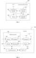
- FIG. 3 is a block diagram of an apparatus for configuring an RS set according to an exemplary embodiment.
- the apparatus has the function of implementing the above method example on the terminal side described above.
- the function may be implemented by hardware or implemented by executing corresponding software by hardware.
- the apparatus may be the terminal described above, or may be disposed in the terminal.
- the apparatus 400 may include an acquiring module 310, a sending module 320 and a receiving module 330.
- the acquiring module 310 is configured to acquire a channel measurement result, wherein the channel measurement result includes channel measurement parameters corresponding to n RSs in a target RS set and channel measurement parameters corresponding to m other RSs outside the target RS set, both n and m being positive integers.
- the sending module 320 is configured to send a measurement report to an access network device in response to the channel measurement result meeting a preset condition, wherein the measurement report is configured to trigger the access network device to update the target RS set.
- the receiving module 330 is configured to receive RS set update information from the access network device, wherein the RS set update information is configured to indicate RSs in the updated target RS set.
- the channel measurement result is acquired by the terminal, and the measurement report is sent to the access network device when the channel measurement result meets the preset condition, such that the access network device promptly updates the target RS set based on the measurement report.
- the access network device is allowed to maintain a target RS set having a large channel measurement parameter for the terminal, which helps to reduce the probability of a beam failure or to improve the success rate of a beam failure recovery.
- the target RS set is an RS set configured to detect a beam failure or a radio link failure, or the target RS set is an RS set configured to determine a candidate beam during a beam failure recovery.
- the measurement report includes identification information of k RSs and indication information of the channel measurement parameters corresponding to the k RSs, wherein k is an integer greater than 1; wherein the k RSs include the n RSs and at least one other RS, with the channel measurement parameter being greater than the channel measurement parameter corresponding to a target RS, in the m other RSs, wherein the target RS is an RS with a minimum channel measurement parameter in the n RSs.
- the indication information of the channel measurement parameter corresponding to an optimal RS is represented by a bits, wherein the optimal RS is an RS with a maximum channel measurement parameter in the k RSs, and a is a positive integer.
- the indication information of the channel measurement parameter corresponding to each remaining RS other than the optimal RS is represented by b bits, wherein b is a positive integer.
- the indication information of the channel measurement parameter corresponding to an i th remaining RS is configured to indicate a difference between the channel measurement parameter corresponding to the i th remaining RS and the channel measurement parameter corresponding to the optimal RS, or to indicate that the channel measurement parameter corresponding to the i th remaining RS is less than a present threshold, wherein i is a positive integer.
- the preset condition includes any one of: the first W RSs of all the RSs included in the channel measurement result, ranked based on the channel measurement parameters in a descending order, being different from the channel measurement results previously acquired channel, w being a positive integer; or the channel measurement parameter corresponding to at least one RS in the target RS set being less than a first threshold value; or a sum of the channel measurement parameter corresponding to at least one RS in the target RS set and a preset offset being less than a maximum value of the channel measurement parameters corresponding to the m other RSs; or the channel measurement parameter corresponding to at least one other RS in the m other RSs being greater than a second threshold value; or the channel measurement parameter corresponding to at least one RS in the target RS set being less than a third threshold value, and the channel measurement parameter corresponding to at least one other RS in the m other RSs being
- the receiving module 330 is further configured to receive configuration information from the access network device.
- the configuration information includes at least one of: measurement object configuration information, measurement parameter configuration information, report trigger configuration information, and report content configuration information.
- the measurement object configuration information is configured to indicate an RS that needs to acquire the channel measurement parameter
- the measurement parameter configuration information is configured to indicate a type of the channel measurement parameter
- the report trigger configuration information is configured to indicate the preset condition that needs to be met when the measurement report is sent to the access network device
- the report content configuration information is configured to indicate content that needs to be contained when the measurement report is sent to the access network device.
- FIG. 4 is a block diagram of an apparatus for configuring an RS set according to another exemplary embodiment.
- the apparatus has the function of implementing the above method example on the access network device side described above.
- the function may be implemented by hardware or implemented by executing corresponding software by hardware.
- the apparatus may be the access network device described above, or may be disposed in the access network device.
- the apparatus 400 may include a receiving module 410, an updating module 420 and a sending module 430.
- the receiving module 410 is configured to receive a measurement report, wherein the measurement report is sent by a terminal in response to a channel measurement result meeting a preset condition, the channel measurement result including channel measurement parameters corresponding to n RSs in a target RS set and channel measurement parameters corresponding to m other RSs outside the target RS set, both n and m being positive integers.
- the updating module 420 is configured to update the target RS set based on the measurement report.
- the sending module 430 is configured to send RS set update information to the terminal, wherein the RS set update information is configured to indicate RSs in the updated target RS set.
- the channel measurement result is acquired by the terminal, and the measurement report is sent to the access network device when the channel measurement result meets the preset condition, such that the access network device promptly updates the target RS set based on the measurement report.
- the access network device is allowed to maintain a target RS set having a large channel measurement parameter for the terminal, which helps to reduce the probability of a beam failure or to improve the success rate of a beam failure recovery.
- the target RS set is an RS set configured to detect a beam failure or a radio link failure, or the target RS set is an RS set configured to determine a candidate beam during a beam failure recovery
- the measurement report includes identification information of k RSs and indication information of channel measurement parameters corresponding to the k RSs, wherein k is an integer greater than 1; wherein the k RSs include the n RSs and at least one other RS, with the channel measurement parameter being greater than the channel measurement parameter corresponding to a target RS, in the m other RSs, the target RS being an RS with a minimum channel measurement parameter in the n RSs.
- the updating module 420 is configured to add at least one RS to the target RS set, and/or to delete at least one RS from the target RS set; wherein the channel measurement parameter corresponding to the RS added to the target RS set is greater than the channel measurement parameter corresponding to the RS deleted from the target RS set.
- the sending module 430 is further configured to send configuration information to the terminal, wherein the configuration information includes at least one of the followings: measurement object configuration information, measurement parameter configuration information, report trigger configuration information and report content configuration information; wherein the measurement object configuration information is configured to indicate an RS that needs to acquire the channel measurement parameter, the measurement parameter configuration information is configured to indicate the type of the channel measurement parameter, the report trigger configuration information is configured to indicate the preset condition that needs to be met when the measurement report is sent to the access network device, and the report content configuration information is configured to indicate content that needs to be contained when the measurement report is sent to the access network device.
- the configuration information includes at least one of the followings: measurement object configuration information, measurement parameter configuration information, report trigger configuration information and report content configuration information; wherein the measurement object configuration information is configured to indicate an RS that needs to acquire the channel measurement parameter, the measurement parameter configuration information is configured to indicate the type of the channel measurement parameter, the report trigger configuration information is configured to indicate the preset condition that needs to be met when the measurement report is sent to the access network device, and the
- the apparatus according to the above embodiment only takes division of all the functional modules as an example for explanation during implementation of its functions.
- the above functions can be finished by the different functional modules as required. That is, the internal structure of the device is divided into different functional modules to finish all or part of the functions described above.
- the solution according to the embodiment of the present disclosure is mainly described in terms of interaction between the access network device and the terminal. It may be understood that for implementing the above functions, the network access device and the terminal include corresponding hardware structures and/or software modules for executing various functions. Various exemplary modules and algorithm steps described in conjunction with the embodiments disclosed in the present disclosure may be implemented as hardware or a combination of hardware and computer software. Whether some functions are implemented in the manner of hardware or in the manner that computer software drives the hardware depends on particular applications and design constraints of the technical solutions. A person skilled in the art may implement the described functions with different methods for each of particular applications, but such implementation shall not be regarded as going beyond the scope of the technical solution of the embodiment of the present disclosure.
- FIG. 5 is a schematic structural diagram of a network access device according to an exemplary embodiment.
- An access network device 500 includes a transmitter/receiver 501 and a processor 502.
- the processor 502 may also be a controller and is shown as a "controller/processor 502" in FIG. 5 .
- the transmitter/receiver 501 is configured to support sending and receiving of information between the network access device and the terminal in the foregoing embodiment and also to support communication between the access network device and other network entities.
- the processor 502 executes various functions for communicating with the terminal.
- On an uplink an uplink signal from the terminal is received by an antenna, demodulated (e.g., a high-frequency signal is demodulated to be a baseband signal) by the receiver 501 and further processed by the processor 502 to restore business data and signaling messages sent by the terminal.
- demodulated e.g., a high-frequency signal is demodulated to be a baseband signal
- the business data and the signaling messages are processed by the processor 502 and modulated (e.g., a baseband signal is modulated to be a high-frequency signal) by the transmitter 501 to produce a downlink signal, and the downlink signal is transmitted to the terminal by the antenna.
- modulated e.g., a baseband signal is modulated to be a high-frequency signal
- the downlink signal is transmitted to the terminal by the antenna.
- the foregoing modulating or demodulating function may also be finished by the processor 502.
- the processor 502 is further configured to implement all the steps on the access network device side in the above method embodiments, and/or other steps in the technical solutions described in the embodiments of the present disclosure.
- the access network device 500 may also include a memory 503, and the memory 503 is configured to store program codes and data of the access network device 500.
- the access network device 500 may further include a communication unit 504.
- the communication unit 504 is configured to support communication between the access network device 500 and other network entities (e.g., network devices in a core network).
- the communication unit 504 may be an NG-U interface for supporting communication between the access network device 500 and user plane function (UPF) entities; or the communication unit 504 may also be an NG-C interface for supporting communication between the access network device 500 and access and mobility management function (AMF) entities.
- UPF user plane function
- AMF access and mobility management function
- FIG. 5 only shows a simplified design of the access network device 500.
- the access network device 500 may include any number of transmitters, receivers, processors, controllers, memories, communication units and the like, and all network access devices that may implement the embodiments of the present disclosure are within the scope of protection of the embodiments of the present disclosure.
- FIG. 6 is a schematic structural diagram of a terminal according to an exemplary embodiment.
- the terminal 600 includes a transmitter 601, a receiver 602, and a processor 603.
- the processor may also be a controller and is shown as "controller/processor 603" in FIG. 6 .
- the terminal 600 may further include a modem processor 605, and the modem processor 605 may include an encoder 606, a modulator 607, a decoder 608, and a demodulator 609.
- the transmitter 601 adjusts (e.g., analog converts, filters, amplifies, up-converts, or the like) an output sample and generates an uplink signal.
- the uplink signal is transmitted to the access network device as described in the foregoing embodiment via an antenna.
- the antenna receives a downlink signal from the access network device as described in the foregoing embodiment.
- the receiver 602 adjusts (e.g., filters, amplifies, down-converts, digitizers, or the like) the signal received from the antenna and provides an input sample.
- the encoder 606 receives business data and signaling messages to be transmitted on an uplink, and processes (e.g., formats, encodes and interleaves) the business data and the signaling messages.
- the modulator 607 further processes (e.g., symbol maps and modulates) the encoded business data and signaling messages and provides an output sample.
- the demodulator 609 processes (e.g., demodulates) the input sample and provides a symbol estimate.
- the decoder 608 processes (e.g., de-interleaves and decodes) the symbol estimate and provides the decoded data and signaling messages sent to the terminal 600.
- the encoder 606, the modulator 607, the demodulator 609, and the decoder 608 may be implemented by the synthesized modem processor 605. These units perform processing according to radio access technologies (e.g., access technologies of LTE and other evolution systems) adopted by a radio access network. It should be noted that when the terminal 600 does not include the modem processor 605, the foregoing functions of the modem processor 605 may also be performed by the processor 603.
- radio access technologies e.g., access technologies of LTE and other evolution systems
- the processor 603 controls and manages actions of the terminal 600, and is configured to execute the processing procedure performed by the terminal 600 in the above-mentioned embodiments of the present disclosure.
- the processor 603 is further configured to execute all the steps on the terminal side in the above-mentioned method embodiments, and/or other steps of the technical solutions described in the embodiments of the present disclosure.
- the terminal 600 may include a memory 604 for storing program codes and data of the terminal 600.
- FIG. 6 only shows a simplified design of the terminal 600.
- the terminal 600 may include any number of transmitters, receivers, processors, modem processors, memories and the like, and all terminals that may implement the embodiments of the present disclosure are within the scope of protection of the embodiments of the present disclosure.
- An embodiment of the present disclosure further provides a non-temporary computer-readable storage medium with a computer program stored thereon.
- the computer program when loaded and run by a processor of an access network device, causes the access network device to perform the method for configuring the RS set on the access network device side as described above.
- An embodiment of the present disclosure further provides a non-temporary computer-readable storage medium with a computer program stored thereon.
- the computer program when loaded and run by a processor of a terminal, causes the terminal to perform the method for configuring the RS set on the terminal side as described above.
- a plurality of herein refers to two or more; and the term “and/or” herein describes an association relationship between associated objects, indicating three relationships.
- a and/or B can be expressed as: A exists alone, A and B exist concurrently, B exists alone.
- the symbol “/” generally indicates an "OR" relationship between contextual objects.
Landscapes
- Engineering & Computer Science (AREA)
- Signal Processing (AREA)
- Computer Networks & Wireless Communication (AREA)
- Quality & Reliability (AREA)
- Mobile Radio Communication Systems (AREA)
Claims (7)
- Procédé de configuration d'un ensemble de signaux de référence, RS, appliqué dans un terminal, comprenant :l'acquisition (201) d'un résultat de mesure du canal, dans lequel le résultat de mesure du canal comprend des paramètres de mesure du canal correspondant à n RS dans un ensemble RS cible et des paramètres de mesure du canal correspondant à m autres RS en dehors de l'ensemble RS cibles, n et m étant tous deux des nombres entiers positifs ;l'envoi (202) d'un rapport de mesure à un dispositif de réseau d'accès, lorsque le résultat de la mesure du canal répond à une condition prédéfinie, dans lequel le rapport de mesure est configuré pour inciter le dispositif de réseau d'accès à mettre à jour l'ensemble RS cibles ; etla réception des informations sur la mise à jour de l'ensemble de RS en provenance du dispositif de réseau d'accès, dans lequel les informations sur la mise à jour de l'ensemble de RS sont configurées pour indiquer les RS dans l'ensemble de RS cibles mis à jour,caractérisé par la condition prédéfinie comprenant l'un des éléments suivants :le paramètre de mesure du canal correspondant à au moins un RS de l'ensemble de RS cibles est inférieur à une première valeur seuil ; oule paramètre de mesure du canal correspondant à au moins un autre RS parmi les m autres RS est supérieur à une seconde valeur seuil ; oule paramètre de mesure du canal correspondant à au moins un RS de l'ensemble de RS cibles est inférieur à une troisième valeur seuil, et le paramètre de mesure du canal correspondant à au moins un autre RS parmi les m autres RS est supérieur à une quatrième valeur seuil.
- Procédé selon la revendication 1, dans lequel l'ensemble de RS cibles est un ensemble de RS configurés pour détecter une défaillance de faisceau ou une défaillance de liaison radio, ou l'ensemble de RS cibles est un ensemble de RS configurés pour déterminer un faisceau candidat pendant la récupération d'une défaillance de faisceau.
- Procédé selon la revendication 1, dans lequel le rapport de mesure comprend des informations d'identification de k RS et des informations d'indication des paramètres de mesure du canal correspondant aux k RS, k étant un nombre entier supérieur à 1 ;
dans lequel les k RS comprennent les n RS et au moins un autre RS, le paramètre de mesure du canal étant supérieur au paramètre de mesure du canal correspondant à un RS cible, dans les m autres RS, le RS cible étant un RS avec un paramètre de mesure du canal minimum dans les n RS. - Procédé selon la revendication 3, dans lequeldans les k RS, les informations d'indication du paramètre de mesure du canal correspondant à un RS optimal est représentée par un bit, le RS optimal étant un RS avec un paramètre de mesure du canal maximal dans les k RS, a étant un nombre entier positif ;dans les k RS, les information d'indication du paramètre de mesure du canal correspondant à chaque RS restant autre que le RS optimal est représentée par b bits, b étant un nombre entier positif ; etles informations d'indication du paramètre de mesure du canal correspondant à une iième RS restante est configurée pour indiquer une différence entre le paramètre de mesure du canal correspondant au iième RS restant et le paramètre de mesure du canal correspondant au RS optimal, ou pour indiquer que le paramètre de mesure du canal correspondant au iième RS restant est inférieur à un seuil présent, i étant un nombre entier positif.
- Procédé selon l'une quelconque des revendications 1 à 4, comprenant en outre :la réception des informations de configuration du dispositif de réseau d'accès, dans lequel les informations de configuration comprennent au moins l'une des informations suivantes : les informations de configuration de l'objet de mesure, les informations de configuration du paramètre de mesure, les informations de configuration du déclencheur de rapport et les informations de configuration du contenu du rapport ;dans lequel les informations de configuration de l'objet de mesure sont configurées pour indiquer un RS qui doit acquérir le paramètre de mesure du canal, les informations de configuration du paramètre de mesure sont configurées pour indiquer un type de paramètre de mesure du canal, les informations de configuration du déclencheur de rapport sont configurées pour indiquer la condition prédéfinie qui doit être remplie lorsque le rapport de mesure est envoyé au dispositif de réseau d'accès, et les informations de configuration du contenu du rapport sont configurées pour indiquer le contenu qui doit être contenu lorsque le rapport de mesure est envoyé au dispositif de réseau d'accès.
- Terminal, caractérisé en ce qu'il comprend :un processeur (605) ; etune mémoire (604) pour stocker une instruction exécutable par le processeur ;dans lequel l'instruction, lorsqu'elle est chargée et exécutée par le processeur (605), amène le processeur (605) à effectuer les étapes du procédé comme défini dans l'une quelconque des revendications 1 à 5.
- Support de stockage non transitoire lisible par ordinateur, ayant un programme informatique stocké sur celui-ci, dans lequel le programme informatique, lorsqu'il est chargé et exécuté par un processeur, amène le processeur à effectuer les étapes du procédé comme défini dans l'une quelconque des revendications 1 à 5.
Priority Applications (1)
| Application Number | Priority Date | Filing Date | Title |
|---|---|---|---|
| EP24167474.6A EP4373026A3 (fr) | 2018-09-13 | 2018-09-13 | Procédé et appareil de configuration d'ensemble rs, et dispositif et support de stockage associés |
Applications Claiming Priority (1)
| Application Number | Priority Date | Filing Date | Title |
|---|---|---|---|
| PCT/CN2018/105559 WO2020051845A1 (fr) | 2018-09-13 | 2018-09-13 | Procédé, dispositif, et équipement de configuration d'un ensemble de rs, et support de stockage |
Related Child Applications (2)
| Application Number | Title | Priority Date | Filing Date |
|---|---|---|---|
| EP24167474.6A Division EP4373026A3 (fr) | 2018-09-13 | 2018-09-13 | Procédé et appareil de configuration d'ensemble rs, et dispositif et support de stockage associés |
| EP24167474.6A Division-Into EP4373026A3 (fr) | 2018-09-13 | 2018-09-13 | Procédé et appareil de configuration d'ensemble rs, et dispositif et support de stockage associés |
Publications (3)
| Publication Number | Publication Date |
|---|---|
| EP3852421A1 EP3852421A1 (fr) | 2021-07-21 |
| EP3852421A4 EP3852421A4 (fr) | 2022-05-11 |
| EP3852421B1 true EP3852421B1 (fr) | 2024-07-24 |
Family
ID=65221691
Family Applications (2)
| Application Number | Title | Priority Date | Filing Date |
|---|---|---|---|
| EP18933251.3A Active EP3852421B1 (fr) | 2018-09-13 | 2018-09-13 | Procédé, dispositif, et équipement de configuration d'un ensemble de rs, et support de stockage |
| EP24167474.6A Pending EP4373026A3 (fr) | 2018-09-13 | 2018-09-13 | Procédé et appareil de configuration d'ensemble rs, et dispositif et support de stockage associés |
Family Applications After (1)
| Application Number | Title | Priority Date | Filing Date |
|---|---|---|---|
| EP24167474.6A Pending EP4373026A3 (fr) | 2018-09-13 | 2018-09-13 | Procédé et appareil de configuration d'ensemble rs, et dispositif et support de stockage associés |
Country Status (5)
| Country | Link |
|---|---|
| US (1) | US12538347B2 (fr) |
| EP (2) | EP3852421B1 (fr) |
| CN (2) | CN109314628B (fr) |
| ES (1) | ES2992823T3 (fr) |
| WO (1) | WO2020051845A1 (fr) |
Families Citing this family (7)
| Publication number | Priority date | Publication date | Assignee | Title |
|---|---|---|---|---|
| JP7426395B2 (ja) * | 2019-02-15 | 2024-02-01 | 鴻穎創新有限公司 | ビーム障害回復のための方法及び装置 |
| WO2020218587A1 (fr) * | 2019-04-26 | 2020-10-29 | Sharp Kabushiki Kaisha | Transferts conditionnels et rapports de mesure |
| CN112104395B (zh) * | 2019-06-18 | 2022-03-29 | 华为技术有限公司 | 一种波束检测的方法以及波束检测装置 |
| CN112929921B (zh) * | 2019-12-05 | 2023-01-13 | 维沃移动通信有限公司 | 波束失败恢复方法、终端及网络侧设备 |
| CN114501628B (zh) * | 2020-10-23 | 2026-01-23 | 中国移动通信有限公司研究院 | 信息上报方法、信息接收方法、终端设备及网络设备 |
| US11765733B2 (en) * | 2021-03-31 | 2023-09-19 | Qualcomm Incorporated | Techniques for measurement gap configurations |
| WO2023004753A1 (fr) * | 2021-07-30 | 2023-02-02 | Zte Corporation | Systèmes et procédés de conception et de configuration de signalisation de référence |
Family Cites Families (17)
| Publication number | Priority date | Publication date | Assignee | Title |
|---|---|---|---|---|
| US8208920B2 (en) * | 2008-03-28 | 2012-06-26 | Qualcomm Incorporated | Reference signal management in mobile systems |
| KR101624879B1 (ko) * | 2009-12-23 | 2016-05-30 | 삼성전자주식회사 | 멀티 셀 환경에서의 기준신호 할당 방법, 관리 방법 및 상기 방법이 적용되는 네트워크 장치 및 단말 |
| EP2792181A4 (fr) | 2011-11-07 | 2015-06-24 | Nokia Solutions & Networks Oy | Configuration souple de mesure de canal |
| KR101805340B1 (ko) * | 2014-02-20 | 2017-12-05 | 후지쯔 가부시끼가이샤 | 측정 식별자를 업데이트하기 위한 방법, 장치, 및 시스템 |
| CN107534865A (zh) * | 2015-04-29 | 2018-01-02 | 瑞典爱立信有限公司 | 用于无线网络中的网络间测量的方法和设备 |
| CN106470096B (zh) | 2015-08-14 | 2021-03-23 | 索尼公司 | 用于无线通信的基站侧和用户设备侧的装置及方法 |
| US10505685B2 (en) | 2016-08-26 | 2019-12-10 | Qualcomm Incorporated | Adapting to delay spread variation in wireless communication systems |
| WO2018059487A1 (fr) * | 2016-09-29 | 2018-04-05 | 华为技术有限公司 | Procédé de mesure de ressource radio, procédé de sélection et dispositif |
| CN116321235A (zh) | 2016-09-29 | 2023-06-23 | 华为技术有限公司 | 无线资源选择方法及装置 |
| CN115835395B (zh) * | 2016-11-04 | 2026-04-17 | 中兴通讯股份有限公司 | 一种控制信道的发送方法和装置 |
| EP3535856B1 (fr) | 2016-11-04 | 2020-01-08 | Telefonaktiebolaget LM Ericsson (PUBL) | Procédés et systèmes de gestion de processus de suivi de faisceau et indices |
| CN109478922B (zh) | 2016-11-30 | 2021-01-29 | 华为技术有限公司 | 一种波束管理方法、装置及系统 |
| CN108112030B (zh) * | 2017-08-11 | 2022-06-07 | 中兴通讯股份有限公司 | 信息上报的触发方法和装置、信号的选择方法和装置 |
| US10979917B2 (en) * | 2017-09-16 | 2021-04-13 | Qualcomm Incorporated | Systems and methods for communication beam loss recovery |
| CN108206714B (zh) * | 2017-12-29 | 2025-12-09 | 中兴通讯股份有限公司 | 信道状态信息获取方法及装置 |
| CN108260214B (zh) * | 2018-01-17 | 2025-04-29 | 中兴通讯股份有限公司 | 一种波束监测对象的确定方法及装置 |
| US12500677B2 (en) * | 2018-05-21 | 2025-12-16 | Qualcomm Incorporated | Dynamic search space configuration |
-
2018
- 2018-09-13 WO PCT/CN2018/105559 patent/WO2020051845A1/fr not_active Ceased
- 2018-09-13 CN CN201880001343.6A patent/CN109314628B/zh active Active
- 2018-09-13 EP EP18933251.3A patent/EP3852421B1/fr active Active
- 2018-09-13 CN CN202110256961.9A patent/CN112929147A/zh active Pending
- 2018-09-13 EP EP24167474.6A patent/EP4373026A3/fr active Pending
- 2018-09-13 US US17/275,188 patent/US12538347B2/en active Active
- 2018-09-13 ES ES18933251T patent/ES2992823T3/es active Active
Also Published As
| Publication number | Publication date |
|---|---|
| CN109314628A (zh) | 2019-02-05 |
| WO2020051845A1 (fr) | 2020-03-19 |
| EP4373026A3 (fr) | 2024-07-31 |
| US12538347B2 (en) | 2026-01-27 |
| EP3852421A1 (fr) | 2021-07-21 |
| US20210329652A1 (en) | 2021-10-21 |
| CN112929147A (zh) | 2021-06-08 |
| ES2992823T3 (en) | 2024-12-18 |
| CN109314628B (zh) | 2021-07-02 |
| EP4373026A2 (fr) | 2024-05-22 |
| EP3852421A4 (fr) | 2022-05-11 |
Similar Documents
| Publication | Publication Date | Title |
|---|---|---|
| US11805436B2 (en) | Method, and device for reporting beam measurement report | |
| EP3852421B1 (fr) | Procédé, dispositif, et équipement de configuration d'un ensemble de rs, et support de stockage | |
| US20250016597A1 (en) | Method and device for reporting beam failure, and storage medium | |
| KR102598626B1 (ko) | 2 차 셀 빔 복구 | |
| KR102581022B1 (ko) | 다운 링크 데이터 수신 방법, 송신 방법, 장치 및 저장 매체 | |
| CN114666904B (zh) | 通信方法及装置 | |
| US11316645B2 (en) | Method and apparatus for RMSI reception from a neighboring cell | |
| US12425874B2 (en) | Data transmission method and appartatus and storage medium | |
| US20200084739A1 (en) | Method and apparatus for advanced frequency offset indication | |
| US11343748B2 (en) | Coordinated beam selection in cellular mesh network | |
| US20240381356A1 (en) | Downlink data receiving method and device, downlink data transmitting method and device, and storage medium | |
| US11463213B2 (en) | Processing device for beam monitoring on serving downlink beams and methods thereof | |
| CN115136702A (zh) | Tci状态的指示方法、装置、设备及介质 | |
| CN111385890B (zh) | 一种波束失败恢复方法及装置 | |
| US11638319B2 (en) | Handling radio link failure in cellular mesh networks | |
| JP2024081688A (ja) | ワイヤレス通信におけるリンク回復 | |
| CN115606226B (zh) | 用于选择用于确定波束故障检测和无线电链路监测的参考信号的方法、装备和介质 |
Legal Events
| Date | Code | Title | Description |
|---|---|---|---|
| STAA | Information on the status of an ep patent application or granted ep patent |
Free format text: STATUS: THE INTERNATIONAL PUBLICATION HAS BEEN MADE |
|
| PUAI | Public reference made under article 153(3) epc to a published international application that has entered the european phase |
Free format text: ORIGINAL CODE: 0009012 |
|
| STAA | Information on the status of an ep patent application or granted ep patent |
Free format text: STATUS: REQUEST FOR EXAMINATION WAS MADE |
|
| 17P | Request for examination filed |
Effective date: 20210330 |
|
| AK | Designated contracting states |
Kind code of ref document: A1 Designated state(s): AL AT BE BG CH CY CZ DE DK EE ES FI FR GB GR HR HU IE IS IT LI LT LU LV MC MK MT NL NO PL PT RO RS SE SI SK SM TR |
|
| DAV | Request for validation of the european patent (deleted) | ||
| DAX | Request for extension of the european patent (deleted) | ||
| A4 | Supplementary search report drawn up and despatched |
Effective date: 20220408 |
|
| RIC1 | Information provided on ipc code assigned before grant |
Ipc: H04L 5/00 20060101ALI20220404BHEP Ipc: H04W 24/04 20090101AFI20220404BHEP |
|
| STAA | Information on the status of an ep patent application or granted ep patent |
Free format text: STATUS: EXAMINATION IS IN PROGRESS |
|
| 17Q | First examination report despatched |
Effective date: 20230120 |
|
| GRAP | Despatch of communication of intention to grant a patent |
Free format text: ORIGINAL CODE: EPIDOSNIGR1 |
|
| STAA | Information on the status of an ep patent application or granted ep patent |
Free format text: STATUS: GRANT OF PATENT IS INTENDED |
|
| INTG | Intention to grant announced |
Effective date: 20240226 |
|
| GRAS | Grant fee paid |
Free format text: ORIGINAL CODE: EPIDOSNIGR3 |
|
| P01 | Opt-out of the competence of the unified patent court (upc) registered |
Effective date: 20240503 |
|
| GRAA | (expected) grant |
Free format text: ORIGINAL CODE: 0009210 |
|
| STAA | Information on the status of an ep patent application or granted ep patent |
Free format text: STATUS: THE PATENT HAS BEEN GRANTED |
|
| AK | Designated contracting states |
Kind code of ref document: B1 Designated state(s): AL AT BE BG CH CY CZ DE DK EE ES FI FR GB GR HR HU IE IS IT LI LT LU LV MC MK MT NL NO PL PT RO RS SE SI SK SM TR |
|
| REG | Reference to a national code |
Ref country code: GB Ref legal event code: FG4D |
|
| REG | Reference to a national code |
Ref country code: CH Ref legal event code: EP |
|
| REG | Reference to a national code |
Ref country code: IE Ref legal event code: FG4D Ref country code: DE Ref legal event code: R096 Ref document number: 602018072338 Country of ref document: DE |
|
| REG | Reference to a national code |
Ref country code: NL Ref legal event code: FP |
|
| REG | Reference to a national code |
Ref country code: LT Ref legal event code: MG9D |
|
| PG25 | Lapsed in a contracting state [announced via postgrant information from national office to epo] |
Ref country code: PT Free format text: LAPSE BECAUSE OF FAILURE TO SUBMIT A TRANSLATION OF THE DESCRIPTION OR TO PAY THE FEE WITHIN THE PRESCRIBED TIME-LIMIT Effective date: 20241125 |
|
| REG | Reference to a national code |
Ref country code: AT Ref legal event code: MK05 Ref document number: 1707423 Country of ref document: AT Kind code of ref document: T Effective date: 20240724 |
|
| REG | Reference to a national code |
Ref country code: ES Ref legal event code: FG2A Ref document number: 2992823 Country of ref document: ES Kind code of ref document: T3 Effective date: 20241218 |
|
| PG25 | Lapsed in a contracting state [announced via postgrant information from national office to epo] |
Ref country code: PT Free format text: LAPSE BECAUSE OF FAILURE TO SUBMIT A TRANSLATION OF THE DESCRIPTION OR TO PAY THE FEE WITHIN THE PRESCRIBED TIME-LIMIT Effective date: 20241125 |
|
| PG25 | Lapsed in a contracting state [announced via postgrant information from national office to epo] |
Ref country code: NO Free format text: LAPSE BECAUSE OF FAILURE TO SUBMIT A TRANSLATION OF THE DESCRIPTION OR TO PAY THE FEE WITHIN THE PRESCRIBED TIME-LIMIT Effective date: 20241024 |
|
| PG25 | Lapsed in a contracting state [announced via postgrant information from national office to epo] |
Ref country code: FI Free format text: LAPSE BECAUSE OF FAILURE TO SUBMIT A TRANSLATION OF THE DESCRIPTION OR TO PAY THE FEE WITHIN THE PRESCRIBED TIME-LIMIT Effective date: 20240724 Ref country code: PL Free format text: LAPSE BECAUSE OF FAILURE TO SUBMIT A TRANSLATION OF THE DESCRIPTION OR TO PAY THE FEE WITHIN THE PRESCRIBED TIME-LIMIT Effective date: 20240724 Ref country code: GR Free format text: LAPSE BECAUSE OF FAILURE TO SUBMIT A TRANSLATION OF THE DESCRIPTION OR TO PAY THE FEE WITHIN THE PRESCRIBED TIME-LIMIT Effective date: 20241025 |
|
| PG25 | Lapsed in a contracting state [announced via postgrant information from national office to epo] |
Ref country code: BG Free format text: LAPSE BECAUSE OF FAILURE TO SUBMIT A TRANSLATION OF THE DESCRIPTION OR TO PAY THE FEE WITHIN THE PRESCRIBED TIME-LIMIT Effective date: 20240724 |
|
| PG25 | Lapsed in a contracting state [announced via postgrant information from national office to epo] |
Ref country code: LV Free format text: LAPSE BECAUSE OF FAILURE TO SUBMIT A TRANSLATION OF THE DESCRIPTION OR TO PAY THE FEE WITHIN THE PRESCRIBED TIME-LIMIT Effective date: 20240724 |
|
| PG25 | Lapsed in a contracting state [announced via postgrant information from national office to epo] |
Ref country code: IS Free format text: LAPSE BECAUSE OF FAILURE TO SUBMIT A TRANSLATION OF THE DESCRIPTION OR TO PAY THE FEE WITHIN THE PRESCRIBED TIME-LIMIT Effective date: 20241124 Ref country code: AT Free format text: LAPSE BECAUSE OF FAILURE TO SUBMIT A TRANSLATION OF THE DESCRIPTION OR TO PAY THE FEE WITHIN THE PRESCRIBED TIME-LIMIT Effective date: 20240724 |
|
| PG25 | Lapsed in a contracting state [announced via postgrant information from national office to epo] |
Ref country code: HR Free format text: LAPSE BECAUSE OF FAILURE TO SUBMIT A TRANSLATION OF THE DESCRIPTION OR TO PAY THE FEE WITHIN THE PRESCRIBED TIME-LIMIT Effective date: 20240724 |
|
| PG25 | Lapsed in a contracting state [announced via postgrant information from national office to epo] |
Ref country code: RS Free format text: LAPSE BECAUSE OF FAILURE TO SUBMIT A TRANSLATION OF THE DESCRIPTION OR TO PAY THE FEE WITHIN THE PRESCRIBED TIME-LIMIT Effective date: 20241024 |
|
| PG25 | Lapsed in a contracting state [announced via postgrant information from national office to epo] |
Ref country code: RS Free format text: LAPSE BECAUSE OF FAILURE TO SUBMIT A TRANSLATION OF THE DESCRIPTION OR TO PAY THE FEE WITHIN THE PRESCRIBED TIME-LIMIT Effective date: 20241024 Ref country code: PL Free format text: LAPSE BECAUSE OF FAILURE TO SUBMIT A TRANSLATION OF THE DESCRIPTION OR TO PAY THE FEE WITHIN THE PRESCRIBED TIME-LIMIT Effective date: 20240724 Ref country code: NO Free format text: LAPSE BECAUSE OF FAILURE TO SUBMIT A TRANSLATION OF THE DESCRIPTION OR TO PAY THE FEE WITHIN THE PRESCRIBED TIME-LIMIT Effective date: 20241024 Ref country code: LV Free format text: LAPSE BECAUSE OF FAILURE TO SUBMIT A TRANSLATION OF THE DESCRIPTION OR TO PAY THE FEE WITHIN THE PRESCRIBED TIME-LIMIT Effective date: 20240724 Ref country code: IS Free format text: LAPSE BECAUSE OF FAILURE TO SUBMIT A TRANSLATION OF THE DESCRIPTION OR TO PAY THE FEE WITHIN THE PRESCRIBED TIME-LIMIT Effective date: 20241124 Ref country code: HR Free format text: LAPSE BECAUSE OF FAILURE TO SUBMIT A TRANSLATION OF THE DESCRIPTION OR TO PAY THE FEE WITHIN THE PRESCRIBED TIME-LIMIT Effective date: 20240724 Ref country code: GR Free format text: LAPSE BECAUSE OF FAILURE TO SUBMIT A TRANSLATION OF THE DESCRIPTION OR TO PAY THE FEE WITHIN THE PRESCRIBED TIME-LIMIT Effective date: 20241025 Ref country code: FI Free format text: LAPSE BECAUSE OF FAILURE TO SUBMIT A TRANSLATION OF THE DESCRIPTION OR TO PAY THE FEE WITHIN THE PRESCRIBED TIME-LIMIT Effective date: 20240724 Ref country code: BG Free format text: LAPSE BECAUSE OF FAILURE TO SUBMIT A TRANSLATION OF THE DESCRIPTION OR TO PAY THE FEE WITHIN THE PRESCRIBED TIME-LIMIT Effective date: 20240724 Ref country code: AT Free format text: LAPSE BECAUSE OF FAILURE TO SUBMIT A TRANSLATION OF THE DESCRIPTION OR TO PAY THE FEE WITHIN THE PRESCRIBED TIME-LIMIT Effective date: 20240724 |
|
| PG25 | Lapsed in a contracting state [announced via postgrant information from national office to epo] |
Ref country code: DK Free format text: LAPSE BECAUSE OF FAILURE TO SUBMIT A TRANSLATION OF THE DESCRIPTION OR TO PAY THE FEE WITHIN THE PRESCRIBED TIME-LIMIT Effective date: 20240724 Ref country code: SM Free format text: LAPSE BECAUSE OF FAILURE TO SUBMIT A TRANSLATION OF THE DESCRIPTION OR TO PAY THE FEE WITHIN THE PRESCRIBED TIME-LIMIT Effective date: 20240724 Ref country code: RO Free format text: LAPSE BECAUSE OF FAILURE TO SUBMIT A TRANSLATION OF THE DESCRIPTION OR TO PAY THE FEE WITHIN THE PRESCRIBED TIME-LIMIT Effective date: 20240724 |
|
| PG25 | Lapsed in a contracting state [announced via postgrant information from national office to epo] |
Ref country code: MC Free format text: LAPSE BECAUSE OF FAILURE TO SUBMIT A TRANSLATION OF THE DESCRIPTION OR TO PAY THE FEE WITHIN THE PRESCRIBED TIME-LIMIT Effective date: 20240724 Ref country code: EE Free format text: LAPSE BECAUSE OF FAILURE TO SUBMIT A TRANSLATION OF THE DESCRIPTION OR TO PAY THE FEE WITHIN THE PRESCRIBED TIME-LIMIT Effective date: 20240724 |
|
| PG25 | Lapsed in a contracting state [announced via postgrant information from national office to epo] |
Ref country code: CZ Free format text: LAPSE BECAUSE OF FAILURE TO SUBMIT A TRANSLATION OF THE DESCRIPTION OR TO PAY THE FEE WITHIN THE PRESCRIBED TIME-LIMIT Effective date: 20240724 |
|
| REG | Reference to a national code |
Ref country code: DE Ref legal event code: R097 Ref document number: 602018072338 Country of ref document: DE |
|
| PG25 | Lapsed in a contracting state [announced via postgrant information from national office to epo] |
Ref country code: SK Free format text: LAPSE BECAUSE OF FAILURE TO SUBMIT A TRANSLATION OF THE DESCRIPTION OR TO PAY THE FEE WITHIN THE PRESCRIBED TIME-LIMIT Effective date: 20240724 |
|
| REG | Reference to a national code |
Ref country code: CH Ref legal event code: PL |
|
| PG25 | Lapsed in a contracting state [announced via postgrant information from national office to epo] |
Ref country code: LU Free format text: LAPSE BECAUSE OF NON-PAYMENT OF DUE FEES Effective date: 20240913 |
|
| PLBE | No opposition filed within time limit |
Free format text: ORIGINAL CODE: 0009261 |
|
| STAA | Information on the status of an ep patent application or granted ep patent |
Free format text: STATUS: NO OPPOSITION FILED WITHIN TIME LIMIT |
|
| 26N | No opposition filed |
Effective date: 20250425 |
|
| REG | Reference to a national code |
Ref country code: BE Ref legal event code: MM Effective date: 20240930 |
|
| PG25 | Lapsed in a contracting state [announced via postgrant information from national office to epo] |
Ref country code: BE Free format text: LAPSE BECAUSE OF NON-PAYMENT OF DUE FEES Effective date: 20240930 |
|
| PG25 | Lapsed in a contracting state [announced via postgrant information from national office to epo] |
Ref country code: CH Free format text: LAPSE BECAUSE OF NON-PAYMENT OF DUE FEES Effective date: 20240930 |
|
| PG25 | Lapsed in a contracting state [announced via postgrant information from national office to epo] |
Ref country code: IE Free format text: LAPSE BECAUSE OF NON-PAYMENT OF DUE FEES Effective date: 20240913 |
|
| PG25 | Lapsed in a contracting state [announced via postgrant information from national office to epo] |
Ref country code: SE Free format text: LAPSE BECAUSE OF FAILURE TO SUBMIT A TRANSLATION OF THE DESCRIPTION OR TO PAY THE FEE WITHIN THE PRESCRIBED TIME-LIMIT Effective date: 20240724 |
|
| PGFP | Annual fee paid to national office [announced via postgrant information from national office to epo] |
Ref country code: DE Payment date: 20250919 Year of fee payment: 8 |
|
| PGFP | Annual fee paid to national office [announced via postgrant information from national office to epo] |
Ref country code: NL Payment date: 20250918 Year of fee payment: 8 Ref country code: IT Payment date: 20250923 Year of fee payment: 8 |
|
| PGFP | Annual fee paid to national office [announced via postgrant information from national office to epo] |
Ref country code: GB Payment date: 20250919 Year of fee payment: 8 |
|
| PGFP | Annual fee paid to national office [announced via postgrant information from national office to epo] |
Ref country code: FR Payment date: 20250922 Year of fee payment: 8 |
|
| PG25 | Lapsed in a contracting state [announced via postgrant information from national office to epo] |
Ref country code: CY Free format text: LAPSE BECAUSE OF FAILURE TO SUBMIT A TRANSLATION OF THE DESCRIPTION OR TO PAY THE FEE WITHIN THE PRESCRIBED TIME-LIMIT; INVALID AB INITIO Effective date: 20180913 |
|
| PGFP | Annual fee paid to national office [announced via postgrant information from national office to epo] |
Ref country code: ES Payment date: 20251030 Year of fee payment: 8 |
|
| PG25 | Lapsed in a contracting state [announced via postgrant information from national office to epo] |
Ref country code: HU Free format text: LAPSE BECAUSE OF FAILURE TO SUBMIT A TRANSLATION OF THE DESCRIPTION OR TO PAY THE FEE WITHIN THE PRESCRIBED TIME-LIMIT; INVALID AB INITIO Effective date: 20180913 |