EP3852610B1 - Système de chambre cutanée pour microscopie intravitale - Google Patents
Système de chambre cutanée pour microscopie intravitale Download PDFInfo
- Publication number
- EP3852610B1 EP3852610B1 EP19773338.9A EP19773338A EP3852610B1 EP 3852610 B1 EP3852610 B1 EP 3852610B1 EP 19773338 A EP19773338 A EP 19773338A EP 3852610 B1 EP3852610 B1 EP 3852610B1
- Authority
- EP
- European Patent Office
- Prior art keywords
- frame
- frame part
- skin
- folding
- chamber system
- Prior art date
- Legal status (The legal status is an assumption and is not a legal conclusion. Google has not performed a legal analysis and makes no representation as to the accuracy of the status listed.)
- Active
Links
Images

Classifications
-
- A—HUMAN NECESSITIES
- A61—MEDICAL OR VETERINARY SCIENCE; HYGIENE
- A61B—DIAGNOSIS; SURGERY; IDENTIFICATION
- A61B17/00—Surgical instruments, devices or methods
- A61B17/02—Surgical instruments, devices or methods for holding wounds open, e.g. retractors; Tractors
-
- A—HUMAN NECESSITIES
- A61—MEDICAL OR VETERINARY SCIENCE; HYGIENE
- A61B—DIAGNOSIS; SURGERY; IDENTIFICATION
- A61B5/00—Measuring for diagnostic purposes; Identification of persons
- A61B5/0059—Measuring for diagnostic purposes; Identification of persons using light, e.g. diagnosis by transillumination, diascopy, fluorescence
- A61B5/0082—Measuring for diagnostic purposes; Identification of persons using light, e.g. diagnosis by transillumination, diascopy, fluorescence adapted for particular medical purposes
-
- A—HUMAN NECESSITIES
- A61—MEDICAL OR VETERINARY SCIENCE; HYGIENE
- A61B—DIAGNOSIS; SURGERY; IDENTIFICATION
- A61B5/00—Measuring for diagnostic purposes; Identification of persons
- A61B5/70—Means for positioning the patient in relation to the detecting, measuring or recording means
-
- A—HUMAN NECESSITIES
- A61—MEDICAL OR VETERINARY SCIENCE; HYGIENE
- A61D—VETERINARY INSTRUMENTS, IMPLEMENTS, TOOLS, OR METHODS
- A61D1/00—Surgical instruments for veterinary use
-
- A—HUMAN NECESSITIES
- A61—MEDICAL OR VETERINARY SCIENCE; HYGIENE
- A61B—DIAGNOSIS; SURGERY; IDENTIFICATION
- A61B17/00—Surgical instruments, devices or methods
- A61B2017/00831—Material properties
- A61B2017/00902—Material properties transparent or translucent
- A61B2017/00907—Material properties transparent or translucent for light
-
- A—HUMAN NECESSITIES
- A61—MEDICAL OR VETERINARY SCIENCE; HYGIENE
- A61B—DIAGNOSIS; SURGERY; IDENTIFICATION
- A61B2503/00—Evaluating a particular growth phase or type of persons or animals
- A61B2503/40—Animals
-
- A—HUMAN NECESSITIES
- A61—MEDICAL OR VETERINARY SCIENCE; HYGIENE
- A61B—DIAGNOSIS; SURGERY; IDENTIFICATION
- A61B2503/00—Evaluating a particular growth phase or type of persons or animals
- A61B2503/42—Evaluating a particular growth phase or type of persons or animals for laboratory research
-
- A—HUMAN NECESSITIES
- A61—MEDICAL OR VETERINARY SCIENCE; HYGIENE
- A61B—DIAGNOSIS; SURGERY; IDENTIFICATION
- A61B5/00—Measuring for diagnostic purposes; Identification of persons
- A61B5/48—Other medical applications
- A61B5/4887—Locating particular structures in or on the body
- A61B5/489—Blood vessels
Definitions
- the invention relates to a skin chamber system for intravital microscopy (IVM), i.e. microscopy in or on the living organism.
- IVM intravital microscopy
- Intravital microscopy is used in biomedical research to study biological dynamic processes with cellular and subcellular resolution in their natural environment over time.
- IVM Intravital microscopy
- a skin chamber system for example a dorsal chamber system (dorsal chamber system)
- the migration and proliferation of cells in the subcutaneous tissue of mice or rats in particular can be repeatedly observed, examined and visualized microscopically over days to weeks within an animal, without that surgical interventions have to be carried out again and again (cf. Prunier et al., 2017).
- the skin chamber systems known in the prior art are often implemented as dorsal skin chamber systems and include (cf. e.g WO2015/135992 A1, Palmer et al. 2011 , Prunier et al. 2017, US 2018/0154073 A1, Sobolik et al. 2015 ) a frame device (frame structure) as a supporting structure for a skin piece (a skin area, skin section).
- the known (supporting) frame devices usually consist of two complementary and usually approximately congruent plates which have a window-like opening (recess) and are arranged at a distance and in mirror image to one another.
- the intermediate space formed by the distance serves to accommodate the piece of skin, namely a skin fold, in particular a dorsal skin fold of the animal on which the skin chamber system is mounted.
- the two plates are usually connected to each other by a nut and bolt system, the screws passing through pre-punched holes in the skin fold enclosed between the two plates and thus fixing the frame device or the (dorsal) skin chamber system to the animal.
- a transparent cover can be fitted into the window-like opening/recess of the plates, so that there is an observation window on the (back) skin of the animal in question clamped between the plates of the frame device. At this point the skin of this animal is prepared.
- the observation window exists for example made of glass and is fastened for example with a snap ring in the opening/recess. Through the observation window, the prepared skin can be observed microscopically for several days to weeks and can be documented.
- the known skin chamber systems allow repeated direct intravital microscopic observation of one and the same test animal for no longer than about 2 weeks (cf. Palmer et al. 2011).
- the object of the present invention is to provide a skin chamber system in which these disadvantages are avoided.
- a skin chamber system with a frame device (frame structure, frame structure) that is designed as a U-shaped folding frame a U-shaped outer frame part and a U-shaped inner frame part is realized.
- frame device frame structure, frame structure
- These two frame parts are coupled to one another at the open ends of their U-legs by means of a joint connection in such a way that the inner frame part can be folded (pivoted) against the outer frame part - preferably by at least about 180° - so that in the folded (swiveled in) state the inner frame part can be positioned or positioned within the U-opening of the outer frame part, and when folded out (swiveled out) the inner frame part and the outer frame part are mirror images of each other and with an opening angle of 180° ideally a four-sided opening with two pairs of sides enclose or enclose opposite sides of approximately the same length.
- the outer frame part and the inner frame part each have an L-shaped profile in cross section, so that each frame part has a U-shaped frame wall that is horizontal with respect to the folding frame plane and a U-shaped frame wall that is vertical with respect to the folding frame plane.
- the two frame parts are aligned with one another in such a way that, in the closed folding frame position, their vertical frame walls run approximately parallel to one another and their horizontal frame walls are aligned essentially in the same plane and in opposite directions to one another.
- the cross section of the two frame parts in the closed folding frame position thus shows that the two L-profile legs, which run vertically with respect to the folding frame plane, of the outer and inner frame parts on the one hand run approximately parallel to one another, and that the two L-profile legs that are horizontal with respect to the folding frame plane of the outer and on the other hand, the inner frame part are essentially in the same plane and aligned in opposite directions to one another.
- the L-profile of the outer and inner frame part makes it possible to place both the skin edges on the U-shaped skin flap and the skin edges along the skin opening on the two U-shaped frame parts when inserting the folding frame into the skin of the animal (or human). and to ensure that when the folding frame is closed, direct contact between the wound edges of the skin flap and the skin opening is prevented and the skin cannot grow back together at these edges while the folding frame is closed.
- the frame walls of the outer frame part and / or the inner frame part should be on the Leg ends have rounded edges in order to minimize tissue irritation and/or injuries in the skin chamber system in use, in particular when opening and closing the folding frame.
- the articulated connection should preferably be arranged at the ends of the U-legs of the inner and outer frame parts in such a way that when the folding frame is opened by folding out (pivoting out) the inner frame part from the outer frame part or when the folding frame is being closed by folding in (pivoting in) the inner frame part into the outer frame part, the leg ends of the inner frame part do not overhang the leg ends and frame walls of the outer frame part, i.e. are not led beyond them. This avoids impairments or mechanical irritation of the surrounding tissue when the folding frame is opened or closed.
- the joint connection of the folding frame is implemented as a hinge which has two eyelets and a connecting pin and is formed on the two vertical frame walls of the outer and inner frame part.
- the eyelets are preferably each implemented as a hole in the vertical frame wall of the inner frame part and in the vertical frame wall of the outer frame part and in each case near the free U-leg ends.
- the connecting pin is designed and arranged in the two eyelets in such a way that it does not protrude from the pin channel formed by the two eyelets. This further minimizes tissue irritation when the skin chamber system is in use.
- the outer and/or inner frame part each have through-holes in their horizontal frame wall, which are arranged individually or in groups, for example in pairs.
- these through bores or holes are provided for the sutures.
- the profile of the outer frame part and inner frame part which is L-shaped in cross section, can be isosceles or unequal shanks, i.e. the vertical and horizontal frame wall of a frame part can have the same height (or depth) or differ in height (or depth). .
- the corresponding (mutually corresponding) frame walls of the inner and outer frame parts can have the same height (or depth) or differ in their height (or depth).
- the vertical frame wall of the inner frame part of the folding frame is higher than the vertical frame wall of the outer frame part.
- the vertical frame wall points i.e. the cross-section points to the L-inside of the L-profile
- at least one elongated depression is formed centrally and following the U-shape.
- through-holes are provided for a suture guide, these are preferably arranged in the elongate recess(es).
- the folding frame has a projection in the area of its U-base on the horizontal frame wall of the outer frame part (when considering the cross section of this outer frame part in the plane of the horizontal L-profile leg), which, for example, has the shape of a tab can have.
- This projection can serve as a handle or lever when closing and opening the snap frame, as long as it is not already used on an animal (or human).
- the projection serves as a stabilizing abutment when the folding frame is opened by unfolding the inner frame part with the skin flap attached.
- a projection is preferably also formed on the vertical frame wall of the inner frame part (when considering the cross section of this inner frame part in the plane of the vertical L-profile leg), which can also have the shape of a tab, for example.
- This overhang serves to make it easier to grip the inner frame part, in particular when folding it out of the outer frame part, i.e. when opening the folding frame.
- anchoring means for such auxiliary tools in this projection for example blind holes or through-holes.
- the projections of the inner and outer frame parts in the area of the U-base of the folding frame can also be designed and shaped in such a way that they interact in the manner of a handle construction, so that the inner frame part can be folded out without special auxiliary tools, preferably directly by hand, and thus the Snap frame can be opened.
- Stainless steel, titanium and biocompatible plastics such as in particular polyethylene (PE), polyvinyl chloride (PVC), acrylic glass (PMMA), polycarbonate (PC), each individually or Combinations of these have proven themselves in practice.
- PE polyethylene
- PVC polyvinyl chloride
- PMMA acrylic glass
- PC polycarbonate
- the inner and outer frame parts in particular are made entirely or predominantly from biocompatible plastics. This reduces the weight of the U-frame parts and further improves tissue integration. This weight reduction is a significant advantage, particularly when used in smaller mammalian species such as mice.
- a coating made of a non-biological or biological Material that promotes adhesion between skin tissue and the snap frame surface or reduces immunological rejection of the frame is provided.
- This coating can be implemented in such a way that it can be renewed in the short term and without any special technical effort, or it can be designed as a permanently installed coating on the frame surface.
- Tissue adhesive in particular fibrin adhesive, which can be sprayed or brushed onto the surface of the frame wall/frame walls in question, is preferably proposed as the material for the short-lived coating.
- a film coating is quick and easy to produce and can or should be renewed from time to time.
- the fixation of the contact surfaces of the folding frame parts on the skin tissue is achieved by a combination of surgical sutures and tissue adhesive.
- a material is preferably proposed that comprises a porous matrix based on polycarbonate and/or calcium and/or silica and/or other suitable materials , where the pores are interconnected to form a network of cavities ("open porosity matrix").
- Materials of this type are known to be suitable for promoting, ie for stimulating and supporting, the growth of cells into the coating. With a purposefully generated variation in the size of the pores and the connecting cavities (channels) between the pores, the ingrowth of a differentiated vascular system with blood vessels of different thicknesses and therefore differentiated differently can be promoted.
- a skin chamber system according to the invention with a U-shaped folding frame, the inner and/or outer frame part of which has a coating according to the invention, offers the advantage that the coated frame parts can initially be attached with the aid of a subcutaneous suture in or on the skin of the animal (or human ) are anchored, but that these subcutaneous suture threads can be removed again after approx. 1-2 weeks, because experience has shown that the frame is sufficiently firmly connected to the surrounding skin tissue or has grown together after this period of time.
- the skin chamber system according to the invention with a U-shaped folding frame allows specifically, in an experimental animal, the stabilization of a skin flap for repeated, long-term, multimodal imaging of the subcutaneous skin and for repeated, and long-term optical and physical access to experimental tumors or objects implanted in the skin.
- Optical access includes various methods of microscopy, from regular, two-dimensional brightfield and fluorescence microscopy to three-dimensional techniques such as confocal or two-photon microscopy.
- This skin chamber system is ideally suited for the microscopic observation and research of subcutaneously implanted materials, cells, tumors and sensors in vivo and in situ, and it can in principle be used in all animal species with multi-layered skin and also in humans.
- the skin chamber system according to the invention is preferably applied to a test animal using a method which comprises the following steps, all of which should be carried out under sterile conditions:
- a U-shaped incision line with the dimensions of the folding frame to be used is marked on the skin of the anesthetized and analgesic test animal that is free of hair (ie primarily hairless or free of fur).
- An incision, for example a scalpel incision is made through the skin along this U-shaped marking line (marker line), the depth of which extends from the upper skin (epidermis) to the lower layer (subcutis), but not through the underlying fascia and muscle layers.
- the procedure is preferably such that the cutting line (cutting track) along the U-legs, viewed from the base of the U, initially runs in or parallel to the U-leg marking lines and in the end section of each U -leg is led away from this and the U-opening at a slight angle, so that the distance between the two opposite ends of the cutting line is wider than the distance between the ends of the U-legs of the marking line.
- the distance between the two ends of the cutting line should be approximately the same as the distance between the free edges of the horizontal frame walls of the outer frame part, so that after the folding frame has been inserted, the ends of the U-legs of the inner and outer frame parts can be connected to the articulated connections located there are covered by skin and not by the incision.
- the U-shaped skin flap prepared in this way is placed in the level of the subcutaneous layer, at the border between the subcutaneous tissue and the underlying fascial layers, surgically separated from the underlying tissue (dissected free) and folded back, ie folded out distally from the surrounding skin of the animal's back.
- the previously sterilized U-shaped folding frame is inserted into the resulting skin opening on the animal's back in such a way that the outer frame part is placed in the skin opening and the inner frame part can be placed in the open position on the folded-back skin flap.
- the inner frame member is attached to the skin flap and the outer frame member is attached to the adjacent tissue of the skin around the skin opening on/in the animal's back.
- the suture threads are preferably guided from the proximal (ie from "under the subcutis") in a U-shape through the cutis, pulled through the adjacent holes in the horizontal frame wall of the inner frame part and on the free, dem outer frame portion facing surface of the frame wall contracted and knotted.
- the puncture points in the skin flap should be placed in such a way that when the suture is tightened, the skin is pulled slightly towards the frame wall.
- the contact surface of the skin is preferably glued to the respective adjoining surface of the frame wall using a commercially available fabric adhesive, for example cyanoacrylate (eg Histoacryl TM ).
- the inner frame part with the skin flap attached to it is folded into the outer frame part fixed in the wound opening in the animal's back.
- the edges of the wound are preferably also sealed with spray plaster.
- a protective seam can be formed above the joint connection.
- the two corresponding cut edges at the skin opening and skin flap are preferably sewn up at the leg ends of the U-shaped incision channel over the (i.e. distal to) the U-leg ends of the folding frame in the area of the joint connection with a simple suture using surgical thread.
- the folding frame is closed, i.e. before the inner frame part with the skin flap fixed to it is folded into the outer frame part, on the vertical frame wall of the inner frame part, in particular on its U - a (previously sterilised) flexible strap (e.g. a polytetrafluoroethylene/PTFE plastic strap such as that commercially available) on the surface facing the opening of the folding frame, or on its surface facing the vertical frame wall of the outer frame part, or on both available Teflon TM ).
- a flexible strap e.g. a polytetrafluoroethylene/PTFE plastic strap such as that commercially available
- the skin chamber system used should be opened at regular intervals (preferably at least twice a week) to prevent the freely dissected skin flap from growing back together with the tissue in the skin opening in/on the animal's back. Microscopic and other observations as well as manipulations can be carried out.
- the animal For microscopic observation and examination of the subcutaneous tissue on the underside of the skin flap, the animal is anesthetized and the snap frame is slowly opened, removing regrown tissue by careful, blunt detachment (e.g., with blunt scissors or forceps). The animal is then placed on a hot stage under a microscope. The inner frame part with the skin flap is arranged on the heating stage in such a way that the subcutaneous tissue layer points towards the observer or the observation objective. A coverslip can be placed on the subcutaneous skin to smooth the field of view for microscopy.
- Test objects in particular materials or cells or pieces of tumor tissue, can now be implanted in the subcutaneous tissue layer of the skin flap and subjected to long-term observation under approximately natural physiological and morphological conditions.
- the skin chamber system allows the microscopic observation of remodeling processes such as vascular growth and blood flow in experimentally generated tumors over several weeks or even months. These observations provide important new insights for a better understanding and description of essential steps in tumor development. In particular, this also includes tumor invasion and metastasis, both of which determine the clinical picture of a patient and define a therapy scheme tailored to the clinical situation.
- the skin chamber system according to the invention also offers for the first time the possibility of microscopically observing the interactions of implanted materials with the embedding tissue over a period of months or even years. Since many implanted materials remain in the human body for several years, there is a need to be able to make accurate predictions about the performance of implanted materials and structures in living organisms. This need is met by the present invention.
- the new skin chamber system according to the invention offers a significantly expanded area of application compared to conventional skin chamber systems, namely a significantly longer service life (used in the skin), an increase in the measurable area and the introduction of sensors for recording various parameters, even with permanent access when the chamber system is closed.
- the skin chamber system makes it possible for the first time to observe and measure the interaction of orally, intravenously or otherwise administered test substances, such as toxins, nutrients and new drugs, with the tissue in vivo and in real time. Due to the direct, barrier-free access to the tissue with the extensive absence of wounds and other surgical artefacts, a largely natural test situation in a test animal or test person is created here in comparison to other available skin chamber systems or tissue windows. Interactions of test substances with the tissue can be observed and measured both microscopically and by other suitable optical and non-optical detection methods such as Surface-Enhanced Rahman Spectroscopy (SERS).
- SERS Surface-Enhanced Rahman Spectroscopy
- the invention therefore also relates to the use of the skin chamber system according to the invention in a microscopic or non-microscopic method for observing, monitoring, detecting and/or measuring physiological states in In vivo, in particular after tumors and/or tissues and/or sensors and/or other materials have been implanted in the skin of a mammalian organism.
- Example 1 Construction of a folding frame according to the invention of the skin chamber system according to the invention
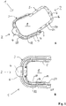
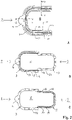
- the U-shaped folding frame 1 comprises a U-shaped outer frame part 3 and a U-shaped inner frame part 5. These two U-frame parts 3, 5 are each coupled to one another at the open ends of their U-legs by a joint connection 7 such that the inner U-frame part 5 can be folded by preferably about 180° against the outer U-frame part 3, so that in the one end position ("closed state)" the inner U-frame part 5 is inside the U-opening of the outer U-frame part 3 is positioned (cf. Fig. 1B and Fig.
- the articulated connection 7 thus enables the inner U-frame part 5 to be folded in and out into or out of the U-opening in the outer U-frame part 3 and thus the folding frame 1 to be opened and closed.
- the joint connection 7, for example a hinge, is arranged at the ends of the U-legs of the inner and outer U-frame parts 5, 3 in such a way that when the folding frame 1 is opened or closed, i.e. when the inner U-frame part 5 is unfolded from the outer U-frame part 3 or when folding the inner U-frame part 5 into the outer U-frame part 3, the leg ends of the inner U-frame part 5 are not guided over the leg ends and frame walls 22, 25 of the outer U-frame part 3.
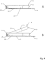
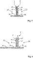
- Outer U-frame part 3 and inner U-frame part 5 each have an L-shaped cross-section (see Fig figure 5 ), which is aligned in such a way that the L-profile legs of the outer and inner U-frame parts 3, 5, which are vertical in relation to the folding frame plane 8, run approximately parallel to one another, almost back to back, and that the L-profile legs that are horizontal in relation to the folding frame plane 8 outer and inner U-frame part 3, 5 in the closed folding frame position are aligned essentially in the same plane and in opposite directions at an angle of (exactly or approximately) 180° to one another.
- each U-frame part 3, 5 has a frame wall 22, 24 that runs horizontally in a U-shape with respect to the folding frame plane 8 and a frame wall 25, 27 that runs vertically in a U-shape with respect to the folding frame plane 8 (cf. 1 ).
- the edges of these frame walls 22, 24, 25, 27 are preferably rounded at the leg ends.
- the articulated connection 7 between the outer and inner U-frame part 3, 5 is arranged on the two vertical frame walls 25, 27 of the outer and inner U-frame part 3, 5.
- the eyelets are each realized as a hole in the vertical frame wall 27 of the inner U-frame part 5 and in the vertical frame wall 25 of the outer U-frame part 3 near the free ends of the U-legs.
- the connector pin 21 is designed not to protrude beyond the pin channel to minimize tissue irritation.
- the dimensioning of the U-shaped folding frame 1 according to the invention is preferably the following:
- the outer U-frame part 3 has an overall length (from the base of the U to the free end of the U-leg) of the order of 31 mm and an overall width (from the free edge of the horizontal side wall of one free U-leg to the free edge of the horizontal side wall of the other free U-leg) in the order of 31 mm.
- Its vertical frame wall 25 has a height of the order of 1 to 4 mm and a thickness of the order of 0.5 mm.
- Its horizontal frame wall 22 has a height or depth of the order of 5 mm and a thickness of the order of 0.5 mm.
- the inner U-frame part 5 has an overall length (from the base of the U to the free end of the U-leg) of the order of 27.5 mm and an overall width (from the free edge of the horizontal side wall of one free U-leg to the free edge of the horizontal side wall of the other free U-leg) in the order of 25 mm.
- Its vertical frame wall 27 has a height of the order of 3 mm and a thickness of the order of 0.5 mm.
- Its horizontal frame wall 24 has a height or depth of the order of 2 to 5 mm and a thickness of the order of 0.5 mm.
- outer and inner U-frame part 3, 5 each in their horizontal frame wall 22, 24 small holes (through holes) 16 of, for example, about 1 mm in diameter, which are grouped individually or, for example, in pairs. These holes 16 are used to guide the sutures when fixing (immobilizing) the folding frame 1 on or in the skin of the test animal (or human) by means of intracutaneous sutures.
- the outer U-frame part 3 On the U-base 2 of the folding frame 1, the outer U-frame part 3 has a bracket-like projection 4 on its horizontal frame wall 22 (ie in the plane of the horizontal L-profile leg) (cf. Figures 1 to 4 ).
- the inner U-frame part 5 has a bracket-like projection 6 on its vertical frame wall 27 (ie in the plane of the vertical L-profile leg) (cf. Fig. 1A and 3 ). Indentations can be formed in or on this projection 6, for example small-diameter holes (through-holes or blind holes), on which an auxiliary tool for folding out this inner U-frame part 5 for the purpose of opening the folding frame 1 can be gripped or attached (fastened).
- projections can be formed on the U-base 2 of the folding frame 1 on the inner and outer U-frame part 5, 3 in such a way that they interact in the manner of a handle construction, so that the inner U-frame part 5 can be removed without special auxiliary tools, preferably directly from Hand, unfolded and thus the folding frame 1 can be opened.
- Such a handle construction can be realized, for example, in such a way that the two projections on the inner and outer U-frame part 5, 3 each have an L-profile in longitudinal section (parallel to the U-axis of symmetry) and are aligned with one another in such a way that the two extend from the U -L-profile limbs extending from the base run parallel to one another, so to speak, back to back, and that the L-profile limbs angled therefrom (with a free head end) are essentially in the same plane and opposite at an angle of (exactly or approximately) 180° to one another in the closed folding frame position aligned so that together they form a "T" in profile.
- the vertical frame walls 25, 27 of the outer and inner U-frame parts 3, 5 can differ in their height or depth.
- the vertical frame wall 27 of the inner U-frame part 5 is higher than the vertical frame wall 25 of the outer U-frame part 3.
- Outer and inner U-frame part 3, 5 can each in their horizontal frame wall 22, 24 (ie in the plane of their horizontal L-profile legs) and in particular in their L-inside 20 of the L-profile (cf. 5 and 6 ) or the surface 30, 32 pointing towards the vertical frame wall 25, 27 approximately in the middle and following the U-shape, have one or more elongated depression(s) (longitudinal groove(s), longitudinal groove(s)) 18 (cf. 1 and 2 ).
- the suture guide holes 16 are preferably located in this/these elongate recess(es) 18 (see Fig Fig. 1B) .
- the areas of the outer and inner U-frame parts 3, 5 that are in direct contact with the skin edges at the U-shaped skin flap and/or with the skin edges along the skin opening, in particular the surfaces of the horizontal frame walls 22, 24 and the vertical frame walls 25 , 27 to the L-inside 20 of the L-profile (cf. 5 and 6 ) point out, can be provided with a coating, which consists of a material, which increases the adhesion between the back skin tissue and the folding frame surface encourages.
- This coating can be a sprayable or brushable film coating, consisting for example of a known fibrin glue or other tissue glue, and which has to be renewed from time to time.
- the fixation of the contact surfaces of the U-frame parts on the skin tissue is achieved in this embodiment by a combination of surgical sutures and tissue adhesive.
- the coating can be formed as a permanently mounted coating on the frame surface.
- the permanently installed coating can consist of a material that comprises a porous matrix in which the pores (e.g. via channels) are connected to form a network (open porous matrix).
- the pores have a diameter of 50-200 ⁇ m and the channels have a diameter of 20-100 ⁇ m.
- the material can be a polycarbonate, a calcium or silica based matrix or other suitable or hardenable material.
- the outside of the coating has larger pores and ports than the inside, thereby promoting ingrowth of tissue bridges and blood vessels which decrease in thickness and diameter as they approach the "bottom" of the coating.
- Example 2 Installation/assembly/establishment of a skin chamber system according to the invention with a folding frame in/on the test animal
- the inserted skin chamber system should be opened at regular intervals (preferably at least twice a week) to prevent the freely dissected skin flap from growing back together with the tissue in the skin opening.
- regular intervals preferably at least twice a week
- Example 3 Implantation of a test object in a skin chamber system mounted (established/installed) on the test animal
- the folding frame of the skin chamber system according to the invention is inserted into the dorsal skin of the test animal in question about 1 week before the planned implantation, as described in Example 2. After three to seven days, the blood supply to the tissue of the skin flap that is fixed to the inner part of the folding frame (cf. example 1) has normalized. Once in this state, the material(s) or cells can be implanted.
- test object e.g. pieces of tumor, new material
- the folding frame is then carefully opened and newly grown tissue is removed by blunt dissection with scissors.
- the wound is then washed with an antibiotic solution.
- fine surgical instruments a small pocket is created (created) tangentially in the exposed subcutaneous tissue on the inside of the skin flap.
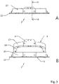
- the test object to be implanted is inserted into the pocket and the pocket is sutured with a thin suture (eg 6-0 non-absorbable monofilament suture). (See. Figure 7A,B )
- the piece of film Before closing, the piece of film is placed between the two U-frame parts in such a way that when the folding frame is closed it is clamped between the inner and outer U-frame parts and thus between the skin flap and the animal's back.
- the length and width of the piece of film are selected in such a way that the films cantilever or protrude beyond the folding frame or the frame walls and U-leg ends of the outer frame part when the folding frame is closed.
- the edge of the film that overhangs or projects beyond the snap frame can and should be cut off just above the frame using scissors.
- test object to be implanted in particular materials or cells come into consideration that are subject to long-term observation under approximately natural physiological and should be subjected to morphological conditions.
- the test object to be implanted can in particular also be a piece of tumor tissue that originates from a tumor that has grown, for example, in another host animal and has been extracted from this.
- the extracted tumor is cut into approx. 2 ⁇ 2 mm pieces in sterile cell culture medium and one of these pieces of tumor tissue is implanted in the pocket created in the subcutaneous tissue of the skin flap.
- the pocket opening is then closed with a thin thread.
Landscapes
- Health & Medical Sciences (AREA)
- Life Sciences & Earth Sciences (AREA)
- Surgery (AREA)
- Veterinary Medicine (AREA)
- Engineering & Computer Science (AREA)
- Animal Behavior & Ethology (AREA)
- General Health & Medical Sciences (AREA)
- Public Health (AREA)
- Biomedical Technology (AREA)
- Molecular Biology (AREA)
- Medical Informatics (AREA)
- Heart & Thoracic Surgery (AREA)
- Physics & Mathematics (AREA)
- Pathology (AREA)
- Biophysics (AREA)
- Zoology (AREA)
- Wood Science & Technology (AREA)
- Nuclear Medicine, Radiotherapy & Molecular Imaging (AREA)
- Surgical Instruments (AREA)
- Prostheses (AREA)
- Investigating Or Analysing Biological Materials (AREA)
Claims (11)
- Système de chambre cutanée avec un dispositif de cadre, caractérisé en ce que le dispositif de cadre est réalisé sous la forme d'un cadre pliable (1) en forme de U avec une partie de cadre extérieure (3) en forme de U et une partie de cadre intérieure (5) en forme de U,- ces deux parties de cadre (3, 5) étant couplées l'une à l'autre à chaque extrémité ouverte de leurs branches en U par une liaison articulée (7) de telle sorte que la partie de cadre intérieure (5) peut être rabattue contre la partie de cadre extérieure (3) de sorte que, à l'état rabattue, la partie de cadre intérieure (5) est positionnée à l'intérieur de l'ouverture en U de la partie de cadre extérieure (3) et, à l'état déplié, la partie de cadre intérieure (5) et la partie de cadre extérieure (3) sont disposées en image miroir l'une par rapport à l'autre et entourent une ouverture,- et la partie de cadre extérieure (3) et la partie de cadre intérieure (5) ayant chacune en coupe transversale un profil en forme de L, de sorte que chaque partie de cadre (3, 5) présente une paroi de cadre (22, 24) en forme de U horizontale par rapport au plan du cadre pliable (8) et une paroi de cadre (25, 27) en forme de U verticale par rapport au plan du cadre pliant (8),- et ces deux parties de cadre (3, 5) étant orientées l'une par rapport à l'autre de telle sorte que, dans le cadre pliable (1) fermé, leurs parois de cadre verticales (25, 27) s'étendent de façon sensiblement parallèle l'une par rapport à l'autre, et leurs parois de cadre horizontales (22, 24) sont orientées sensiblement dans le même plan et en sens opposé l'une de l'autre.
- Système de chambre cutanée selon la revendication 1, caractérisé en ce que la liaison articulée (7) est disposée de telle sorte aux extrémités des branches en U des parties de cadre intérieure et extérieure (5, 3), que lors de l'ouverture du cadre pliable (1) en dépliant la partie de cadre intérieure (5) hors de la partie de cadre extérieure (3), ou lors de la fermeture du cadre pliable (1) en rabattant la partie de cadre intérieure (5) dans la partie de cadre extérieure (3), les extrémités des branches en U de la partie de cadre intérieure (5) ne dépassent pas les extrémités des branches en U et les parois de cadre (22, 25) de la partie de cadre extérieure (3).
- Système de chambre cutanée selon la revendication 1 ou 2, caractérisé en ce que la liaison articulée (7) est une charnière qui est formée sur les deux parois de cadre verticales (25, 27) des parties de cadre extérieure et intérieure (3, 5), et en ce que la charnière (7) comprend deux œillets et une broche de liaison (21), les œillets étant chacun un trou perforé (17, 19) dans la paroi de cadre verticale (27) de la partie de cadre intérieure (5) et dans la paroi de cadre verticale (25) de la partie de cadre extérieure (3) et sont réalisés respectivement à proximité des extrémités libres des branches en U, et la broche de liaison (21) étant disposée dans les deux œillets et réalisée de telle sorte qu'elle ne dépasse pas du canal de broche formé par les deux œillets.
- Système de chambre cutanée selon l'une des revendications 1 à 3, caractérisé en ce que la partie de cadre extérieure et/ou intérieure (3, 5) présente des trous/perçages de passage (16) dans la paroi de cadre horizontale (22, 24), qui sont disposés de façon individuelle ou en groupe.
- Système de chambre cutanée selon l'une des revendications 1 à 4, caractérisé en ce que la paroi de cadre horizontale (22) de la partie de cadre extérieure (3) et/ou la paroi de cadre horizontale (24) de la partie de cadre intérieure (5) présente dans sa surface (30, 32) orientée en coupe transversale vers le côté intérieur en L (20) du profilé en L, au moins un renfoncement allongé (rainure longitudinale, sillon longitudinal) (18) à peu près au milieu et suivant la forme en U.
- Système de chambre cutanée selon l'une des revendications 1 à 5, caractérisé en ce que le matériau de la partie de cadre extérieure et intérieure (3, 5) et de la liaison articulée est choisi dans le groupe constitué de : l'acier inoxydable, le titane et des matières plastiques biocompatibles, comme notamment le polyéthylène (PE), le polychlorure de vinyle (PVC), le verre acrylique (PMMA), le polycarbonate (PC), ainsi que leurs combinaisons.
- Système de chambre cutanée selon l'une des revendications 1 à 6, caractérisé en ce qu'un revêtement constitué d'un matériau favorisant l'adhérence entre le tissu cutané et la paroi de cadre est formé sur les surfaces des parois de cadre horizontales (22, 24) et/ou des parois de cadre verticales (25, 27) qui sont orientées en coupe transversale vers le côté intérieur en L (20) du profilé en L de la partie de cadre extérieure et/ou intérieure (3, 5), est formé.
- Système de chambre cutanée selon la revendication 7, caractérisé en ce que le matériau du revêtement comprend une matrice poreuse à base de polycarbonate et/ou de calcium et/ou de l'acide silicique, dont les pores sont reliés entre eux par des canaux.
- Système de chambre cutanée selon l'une des revendications 1 à 8, caractérisé en ce que la partie de cadre extérieure (3) présente une saillie (4) de type languette sur sa paroi de cadre horizontale (22) au niveau de la base du U (2) du cadre pliable (1).
- Système de chambre cutanée selon l'une des revendications 1 à 9, caractérisé en ce que la partie de cadre intérieure (5) présente une saillie (6) de type languette sur sa paroi de cadre verticale (27) au niveau de la base du U (2) du cadre pliable (1).
- Système de chambre cutanée selon l'une des revendications 1 à 10, destiné à être utilisé dans un procédé microscopique ou non microscopique d'observation, de surveillance, de détection et/ou de mesure d'états physiologiques in vivo.
Applications Claiming Priority (2)
| Application Number | Priority Date | Filing Date | Title |
|---|---|---|---|
| DE102018007340.9A DE102018007340B3 (de) | 2018-09-18 | 2018-09-18 | Hautkammersystem für die Intravitalmikroskopie |
| PCT/DE2019/000211 WO2020057679A1 (fr) | 2018-09-18 | 2019-08-06 | Système de chambre cutanée pour microscopie intravitale |
Publications (2)
| Publication Number | Publication Date |
|---|---|
| EP3852610A1 EP3852610A1 (fr) | 2021-07-28 |
| EP3852610B1 true EP3852610B1 (fr) | 2022-09-14 |
Family
ID=67482219
Family Applications (1)
| Application Number | Title | Priority Date | Filing Date |
|---|---|---|---|
| EP19773338.9A Active EP3852610B1 (fr) | 2018-09-18 | 2019-08-06 | Système de chambre cutanée pour microscopie intravitale |
Country Status (3)
| Country | Link |
|---|---|
| EP (1) | EP3852610B1 (fr) |
| DE (1) | DE102018007340B3 (fr) |
| WO (1) | WO2020057679A1 (fr) |
Families Citing this family (1)
| Publication number | Priority date | Publication date | Assignee | Title |
|---|---|---|---|---|
| CN112451158B (zh) * | 2020-12-04 | 2022-04-19 | 中国人民解放军陆军特色医学中心 | 小白鼠白内障检测装置 |
Family Cites Families (2)
| Publication number | Priority date | Publication date | Assignee | Title |
|---|---|---|---|---|
| FR3018614B1 (fr) | 2014-03-13 | 2016-12-09 | Inst De Cancerologie Gustave Roussy | Plaque de chambre dorsale pour l'imagerie multi-modalite |
| US10117990B2 (en) | 2016-12-07 | 2018-11-06 | The Research Foundation For The State University Of New York | Microfluidic intravital window |
-
2018
- 2018-09-18 DE DE102018007340.9A patent/DE102018007340B3/de not_active Expired - Fee Related
-
2019
- 2019-08-06 WO PCT/DE2019/000211 patent/WO2020057679A1/fr not_active Ceased
- 2019-08-06 EP EP19773338.9A patent/EP3852610B1/fr active Active
Also Published As
| Publication number | Publication date |
|---|---|
| EP3852610A1 (fr) | 2021-07-28 |
| WO2020057679A1 (fr) | 2020-03-26 |
| DE102018007340B3 (de) | 2019-08-22 |
Similar Documents
| Publication | Publication Date | Title |
|---|---|---|
| DE69909830T2 (de) | Vorrichtung zur halterung für mindestens eine medizinische drain | |
| Woolley et al. | Chronic intracortical microelectrode arrays induce non-uniform, depth-related tissue responses | |
| DE69833869T2 (de) | Chirurgische endoskopische schneidvorrichtung | |
| DE69431956T2 (de) | Verstärkungsvorrichtung für weiches gewebe | |
| DE69329334T2 (de) | Systeme für die implantierung von zellen | |
| DE68918943T2 (de) | Gewebeentzusammensetzung und verfahren. | |
| DE60113550T2 (de) | Biomaterial mit tierischem hornhautgewebe | |
| DE69331108T2 (de) | Systeme zum einpflanzen von gefässbildendem gewebe | |
| DE10307487A1 (de) | Verfahren und Vorrichtungen zur verletzungsfreien Bewegung einer Sonde durch biologisches Zellmaterial | |
| EP1077072A2 (fr) | Procédé de préparation in vitro de prothèse de valve cardiaque ou de vaisseaux | |
| DE4400188A1 (de) | Implantat für ein Trommelfell-Loch und Unterseitenkratzer für ein Trommelfell | |
| Prunier et al. | Procedures and applications of long-term intravital microscopy | |
| DE1766712B2 (de) | Vorrichtung zur erzeugung eines in einen lebenden koerper einpflanzbaren gewebeteiles | |
| WO1982003765A1 (fr) | Prothese de la paroi du conduit auditif et procede pour sa fabrication | |
| DE69526389T2 (de) | Offenes gewebe-implantat-system | |
| EP3852610B1 (fr) | Système de chambre cutanée pour microscopie intravitale | |
| DE60117470T2 (de) | Gerät zur auslösung einer immunantwort in der krebstherapie | |
| DE102004003381B4 (de) | Verfahren zur Bestimmung der Lage einer Schicht in einem Untersuchungsgebiet, in welcher Schicht eine Schichtbildaufnahme erfolgen soll | |
| DE112019005432T5 (de) | Nicht biologisch abbaubares antiadhäsionsmaterial | |
| WO2013057207A1 (fr) | Système endoscopique, système de commande et utilisation d'un système de commande pour un système endoscopique | |
| DE102018213872A1 (de) | Vorrichtung und Verfahren zur Bildgebung bei der Implantation von Retinaimplantaten | |
| EP3720387B1 (fr) | Implant doté d'un réservoir | |
| DE102004053596B4 (de) | Verfahren und Vorrichtungen zur Bearbeitung einzelner biologischer Zellen | |
| DE69911679T2 (de) | Bewertung von ischämische Wundheilung-therapeutica | |
| DE68928549T2 (de) | Tiermodell für menschliche krankheit |
Legal Events
| Date | Code | Title | Description |
|---|---|---|---|
| STAA | Information on the status of an ep patent application or granted ep patent |
Free format text: STATUS: UNKNOWN |
|
| STAA | Information on the status of an ep patent application or granted ep patent |
Free format text: STATUS: THE INTERNATIONAL PUBLICATION HAS BEEN MADE |
|
| PUAI | Public reference made under article 153(3) epc to a published international application that has entered the european phase |
Free format text: ORIGINAL CODE: 0009012 |
|
| STAA | Information on the status of an ep patent application or granted ep patent |
Free format text: STATUS: REQUEST FOR EXAMINATION WAS MADE |
|
| 17P | Request for examination filed |
Effective date: 20210213 |
|
| AK | Designated contracting states |
Kind code of ref document: A1 Designated state(s): AL AT BE BG CH CY CZ DE DK EE ES FI FR GB GR HR HU IE IS IT LI LT LU LV MC MK MT NL NO PL PT RO RS SE SI SK SM TR |
|
| DAV | Request for validation of the european patent (deleted) | ||
| DAX | Request for extension of the european patent (deleted) | ||
| GRAP | Despatch of communication of intention to grant a patent |
Free format text: ORIGINAL CODE: EPIDOSNIGR1 |
|
| STAA | Information on the status of an ep patent application or granted ep patent |
Free format text: STATUS: GRANT OF PATENT IS INTENDED |
|
| RIC1 | Information provided on ipc code assigned before grant |
Ipc: A61B 17/00 20060101ALN20220408BHEP Ipc: A61D 1/00 20060101ALI20220408BHEP Ipc: A61B 17/02 20060101ALI20220408BHEP Ipc: A61B 5/00 20060101AFI20220408BHEP |
|
| INTG | Intention to grant announced |
Effective date: 20220513 |
|
| GRAS | Grant fee paid |
Free format text: ORIGINAL CODE: EPIDOSNIGR3 |
|
| GRAA | (expected) grant |
Free format text: ORIGINAL CODE: 0009210 |
|
| STAA | Information on the status of an ep patent application or granted ep patent |
Free format text: STATUS: THE PATENT HAS BEEN GRANTED |
|
| AK | Designated contracting states |
Kind code of ref document: B1 Designated state(s): AL AT BE BG CH CY CZ DE DK EE ES FI FR GB GR HR HU IE IS IT LI LT LU LV MC MK MT NL NO PL PT RO RS SE SI SK SM TR |
|
| REG | Reference to a national code |
Ref country code: GB Ref legal event code: FG4D Free format text: NOT ENGLISH |
|
| REG | Reference to a national code |
Ref country code: CH Ref legal event code: EP |
|
| REG | Reference to a national code |
Ref country code: DE Ref legal event code: R096 Ref document number: 502019005676 Country of ref document: DE |
|
| REG | Reference to a national code |
Ref country code: IE Ref legal event code: FG4D Free format text: LANGUAGE OF EP DOCUMENT: GERMAN |
|
| REG | Reference to a national code |
Ref country code: AT Ref legal event code: REF Ref document number: 1518216 Country of ref document: AT Kind code of ref document: T Effective date: 20221015 |
|
| REG | Reference to a national code |
Ref country code: LT Ref legal event code: MG9D |
|
| REG | Reference to a national code |
Ref country code: NL Ref legal event code: MP Effective date: 20220914 |
|
| PG25 | Lapsed in a contracting state [announced via postgrant information from national office to epo] |
Ref country code: SE Free format text: LAPSE BECAUSE OF FAILURE TO SUBMIT A TRANSLATION OF THE DESCRIPTION OR TO PAY THE FEE WITHIN THE PRESCRIBED TIME-LIMIT Effective date: 20220914 Ref country code: RS Free format text: LAPSE BECAUSE OF FAILURE TO SUBMIT A TRANSLATION OF THE DESCRIPTION OR TO PAY THE FEE WITHIN THE PRESCRIBED TIME-LIMIT Effective date: 20220914 Ref country code: NO Free format text: LAPSE BECAUSE OF FAILURE TO SUBMIT A TRANSLATION OF THE DESCRIPTION OR TO PAY THE FEE WITHIN THE PRESCRIBED TIME-LIMIT Effective date: 20221214 Ref country code: LV Free format text: LAPSE BECAUSE OF FAILURE TO SUBMIT A TRANSLATION OF THE DESCRIPTION OR TO PAY THE FEE WITHIN THE PRESCRIBED TIME-LIMIT Effective date: 20220914 Ref country code: LT Free format text: LAPSE BECAUSE OF FAILURE TO SUBMIT A TRANSLATION OF THE DESCRIPTION OR TO PAY THE FEE WITHIN THE PRESCRIBED TIME-LIMIT Effective date: 20220914 Ref country code: FI Free format text: LAPSE BECAUSE OF FAILURE TO SUBMIT A TRANSLATION OF THE DESCRIPTION OR TO PAY THE FEE WITHIN THE PRESCRIBED TIME-LIMIT Effective date: 20220914 |
|
| PG25 | Lapsed in a contracting state [announced via postgrant information from national office to epo] |
Ref country code: HR Free format text: LAPSE BECAUSE OF FAILURE TO SUBMIT A TRANSLATION OF THE DESCRIPTION OR TO PAY THE FEE WITHIN THE PRESCRIBED TIME-LIMIT Effective date: 20220914 Ref country code: GR Free format text: LAPSE BECAUSE OF FAILURE TO SUBMIT A TRANSLATION OF THE DESCRIPTION OR TO PAY THE FEE WITHIN THE PRESCRIBED TIME-LIMIT Effective date: 20221215 |
|
| PG25 | Lapsed in a contracting state [announced via postgrant information from national office to epo] |
Ref country code: SM Free format text: LAPSE BECAUSE OF FAILURE TO SUBMIT A TRANSLATION OF THE DESCRIPTION OR TO PAY THE FEE WITHIN THE PRESCRIBED TIME-LIMIT Effective date: 20220914 Ref country code: RO Free format text: LAPSE BECAUSE OF FAILURE TO SUBMIT A TRANSLATION OF THE DESCRIPTION OR TO PAY THE FEE WITHIN THE PRESCRIBED TIME-LIMIT Effective date: 20220914 Ref country code: PT Free format text: LAPSE BECAUSE OF FAILURE TO SUBMIT A TRANSLATION OF THE DESCRIPTION OR TO PAY THE FEE WITHIN THE PRESCRIBED TIME-LIMIT Effective date: 20230116 Ref country code: ES Free format text: LAPSE BECAUSE OF FAILURE TO SUBMIT A TRANSLATION OF THE DESCRIPTION OR TO PAY THE FEE WITHIN THE PRESCRIBED TIME-LIMIT Effective date: 20220914 Ref country code: CZ Free format text: LAPSE BECAUSE OF FAILURE TO SUBMIT A TRANSLATION OF THE DESCRIPTION OR TO PAY THE FEE WITHIN THE PRESCRIBED TIME-LIMIT Effective date: 20220914 |
|
| PG25 | Lapsed in a contracting state [announced via postgrant information from national office to epo] |
Ref country code: SK Free format text: LAPSE BECAUSE OF FAILURE TO SUBMIT A TRANSLATION OF THE DESCRIPTION OR TO PAY THE FEE WITHIN THE PRESCRIBED TIME-LIMIT Effective date: 20220914 Ref country code: PL Free format text: LAPSE BECAUSE OF FAILURE TO SUBMIT A TRANSLATION OF THE DESCRIPTION OR TO PAY THE FEE WITHIN THE PRESCRIBED TIME-LIMIT Effective date: 20220914 Ref country code: IS Free format text: LAPSE BECAUSE OF FAILURE TO SUBMIT A TRANSLATION OF THE DESCRIPTION OR TO PAY THE FEE WITHIN THE PRESCRIBED TIME-LIMIT Effective date: 20230114 Ref country code: EE Free format text: LAPSE BECAUSE OF FAILURE TO SUBMIT A TRANSLATION OF THE DESCRIPTION OR TO PAY THE FEE WITHIN THE PRESCRIBED TIME-LIMIT Effective date: 20220914 |
|
| REG | Reference to a national code |
Ref country code: DE Ref legal event code: R097 Ref document number: 502019005676 Country of ref document: DE |
|
| PG25 | Lapsed in a contracting state [announced via postgrant information from national office to epo] |
Ref country code: NL Free format text: LAPSE BECAUSE OF FAILURE TO SUBMIT A TRANSLATION OF THE DESCRIPTION OR TO PAY THE FEE WITHIN THE PRESCRIBED TIME-LIMIT Effective date: 20220914 Ref country code: AL Free format text: LAPSE BECAUSE OF FAILURE TO SUBMIT A TRANSLATION OF THE DESCRIPTION OR TO PAY THE FEE WITHIN THE PRESCRIBED TIME-LIMIT Effective date: 20220914 |
|
| PLBE | No opposition filed within time limit |
Free format text: ORIGINAL CODE: 0009261 |
|
| STAA | Information on the status of an ep patent application or granted ep patent |
Free format text: STATUS: NO OPPOSITION FILED WITHIN TIME LIMIT |
|
| PG25 | Lapsed in a contracting state [announced via postgrant information from national office to epo] |
Ref country code: DK Free format text: LAPSE BECAUSE OF FAILURE TO SUBMIT A TRANSLATION OF THE DESCRIPTION OR TO PAY THE FEE WITHIN THE PRESCRIBED TIME-LIMIT Effective date: 20220914 |
|
| 26N | No opposition filed |
Effective date: 20230615 |
|
| PG25 | Lapsed in a contracting state [announced via postgrant information from national office to epo] |
Ref country code: SI Free format text: LAPSE BECAUSE OF FAILURE TO SUBMIT A TRANSLATION OF THE DESCRIPTION OR TO PAY THE FEE WITHIN THE PRESCRIBED TIME-LIMIT Effective date: 20220914 |
|
| P01 | Opt-out of the competence of the unified patent court (upc) registered |
Effective date: 20240129 |
|
| PG25 | Lapsed in a contracting state [announced via postgrant information from national office to epo] |
Ref country code: MC Free format text: LAPSE BECAUSE OF FAILURE TO SUBMIT A TRANSLATION OF THE DESCRIPTION OR TO PAY THE FEE WITHIN THE PRESCRIBED TIME-LIMIT Effective date: 20220914 |
|
| REG | Reference to a national code |
Ref country code: CH Ref legal event code: PL |
|
| PG25 | Lapsed in a contracting state [announced via postgrant information from national office to epo] |
Ref country code: MC Free format text: LAPSE BECAUSE OF FAILURE TO SUBMIT A TRANSLATION OF THE DESCRIPTION OR TO PAY THE FEE WITHIN THE PRESCRIBED TIME-LIMIT Effective date: 20220914 |
|
| PG25 | Lapsed in a contracting state [announced via postgrant information from national office to epo] |
Ref country code: LU Free format text: LAPSE BECAUSE OF NON-PAYMENT OF DUE FEES Effective date: 20230806 |
|
| PG25 | Lapsed in a contracting state [announced via postgrant information from national office to epo] |
Ref country code: LU Free format text: LAPSE BECAUSE OF NON-PAYMENT OF DUE FEES Effective date: 20230806 Ref country code: CH Free format text: LAPSE BECAUSE OF NON-PAYMENT OF DUE FEES Effective date: 20230831 |
|
| REG | Reference to a national code |
Ref country code: BE Ref legal event code: MM Effective date: 20230831 |
|
| REG | Reference to a national code |
Ref country code: IE Ref legal event code: MM4A |
|
| PG25 | Lapsed in a contracting state [announced via postgrant information from national office to epo] |
Ref country code: IT Free format text: LAPSE BECAUSE OF FAILURE TO SUBMIT A TRANSLATION OF THE DESCRIPTION OR TO PAY THE FEE WITHIN THE PRESCRIBED TIME-LIMIT Effective date: 20220914 |
|
| PG25 | Lapsed in a contracting state [announced via postgrant information from national office to epo] |
Ref country code: IE Free format text: LAPSE BECAUSE OF NON-PAYMENT OF DUE FEES Effective date: 20230806 |
|
| PG25 | Lapsed in a contracting state [announced via postgrant information from national office to epo] |
Ref country code: IE Free format text: LAPSE BECAUSE OF NON-PAYMENT OF DUE FEES Effective date: 20230806 |
|
| PG25 | Lapsed in a contracting state [announced via postgrant information from national office to epo] |
Ref country code: BE Free format text: LAPSE BECAUSE OF NON-PAYMENT OF DUE FEES Effective date: 20230831 |
|
| PG25 | Lapsed in a contracting state [announced via postgrant information from national office to epo] |
Ref country code: BG Free format text: LAPSE BECAUSE OF FAILURE TO SUBMIT A TRANSLATION OF THE DESCRIPTION OR TO PAY THE FEE WITHIN THE PRESCRIBED TIME-LIMIT Effective date: 20220914 |
|
| PG25 | Lapsed in a contracting state [announced via postgrant information from national office to epo] |
Ref country code: BG Free format text: LAPSE BECAUSE OF FAILURE TO SUBMIT A TRANSLATION OF THE DESCRIPTION OR TO PAY THE FEE WITHIN THE PRESCRIBED TIME-LIMIT Effective date: 20220914 |
|
| PG25 | Lapsed in a contracting state [announced via postgrant information from national office to epo] |
Ref country code: CY Free format text: LAPSE BECAUSE OF FAILURE TO SUBMIT A TRANSLATION OF THE DESCRIPTION OR TO PAY THE FEE WITHIN THE PRESCRIBED TIME-LIMIT; INVALID AB INITIO Effective date: 20190806 |
|
| PG25 | Lapsed in a contracting state [announced via postgrant information from national office to epo] |
Ref country code: HU Free format text: LAPSE BECAUSE OF FAILURE TO SUBMIT A TRANSLATION OF THE DESCRIPTION OR TO PAY THE FEE WITHIN THE PRESCRIBED TIME-LIMIT; INVALID AB INITIO Effective date: 20190806 |
|
| PGFP | Annual fee paid to national office [announced via postgrant information from national office to epo] |
Ref country code: DE Payment date: 20250831 Year of fee payment: 7 |
|
| REG | Reference to a national code |
Ref country code: AT Ref legal event code: MM01 Ref document number: 1518216 Country of ref document: AT Kind code of ref document: T Effective date: 20240806 |
|
| PGFP | Annual fee paid to national office [announced via postgrant information from national office to epo] |
Ref country code: GB Payment date: 20250822 Year of fee payment: 7 |
|
| PG25 | Lapsed in a contracting state [announced via postgrant information from national office to epo] |
Ref country code: AT Free format text: LAPSE BECAUSE OF NON-PAYMENT OF DUE FEES Effective date: 20240806 |
|
| PGFP | Annual fee paid to national office [announced via postgrant information from national office to epo] |
Ref country code: FR Payment date: 20250821 Year of fee payment: 7 |
|
| PG25 | Lapsed in a contracting state [announced via postgrant information from national office to epo] |
Ref country code: TR Free format text: LAPSE BECAUSE OF FAILURE TO SUBMIT A TRANSLATION OF THE DESCRIPTION OR TO PAY THE FEE WITHIN THE PRESCRIBED TIME-LIMIT Effective date: 20220914 |
|
| PGFP | Annual fee paid to national office [announced via postgrant information from national office to epo] |
Ref country code: AT Payment date: 20260410 Year of fee payment: 5 |