EP3852832B1 - Procédé de démarrage d'une pompe à sang avec un défaut électrique - Google Patents
Procédé de démarrage d'une pompe à sang avec un défaut électrique Download PDFInfo
- Publication number
- EP3852832B1 EP3852832B1 EP19765888.3A EP19765888A EP3852832B1 EP 3852832 B1 EP3852832 B1 EP 3852832B1 EP 19765888 A EP19765888 A EP 19765888A EP 3852832 B1 EP3852832 B1 EP 3852832B1
- Authority
- EP
- European Patent Office
- Prior art keywords
- speed
- control circuit
- stator
- startup
- motor
- Prior art date
- Legal status (The legal status is an assumption and is not a legal conclusion. Google has not performed a legal analysis and makes no representation as to the accuracy of the status listed.)
- Active
Links
Images




Classifications
-
- A—HUMAN NECESSITIES
- A61—MEDICAL OR VETERINARY SCIENCE; HYGIENE
- A61M—DEVICES FOR INTRODUCING MEDIA INTO, OR ONTO, THE BODY; DEVICES FOR TRANSDUCING BODY MEDIA OR FOR TAKING MEDIA FROM THE BODY; DEVICES FOR PRODUCING OR ENDING SLEEP OR STUPOR
- A61M60/00—Blood pumps; Devices for mechanical circulatory actuation; Balloon pumps for circulatory assistance
- A61M60/10—Location thereof with respect to the patient's body
- A61M60/122—Implantable pumps or pumping devices, i.e. the blood being pumped inside the patient's body
-
- F—MECHANICAL ENGINEERING; LIGHTING; HEATING; WEAPONS; BLASTING
- F04—POSITIVE - DISPLACEMENT MACHINES FOR LIQUIDS; PUMPS FOR LIQUIDS OR ELASTIC FLUIDS
- F04D—NON-POSITIVE-DISPLACEMENT PUMPS
- F04D13/00—Pumping installations or systems
- F04D13/02—Units comprising pumps and their driving means
- F04D13/06—Units comprising pumps and their driving means the pump being electrically driven
-
- A—HUMAN NECESSITIES
- A61—MEDICAL OR VETERINARY SCIENCE; HYGIENE
- A61M—DEVICES FOR INTRODUCING MEDIA INTO, OR ONTO, THE BODY; DEVICES FOR TRANSDUCING BODY MEDIA OR FOR TAKING MEDIA FROM THE BODY; DEVICES FOR PRODUCING OR ENDING SLEEP OR STUPOR
- A61M60/00—Blood pumps; Devices for mechanical circulatory actuation; Balloon pumps for circulatory assistance
- A61M60/10—Location thereof with respect to the patient's body
- A61M60/122—Implantable pumps or pumping devices, i.e. the blood being pumped inside the patient's body
- A61M60/165—Implantable pumps or pumping devices, i.e. the blood being pumped inside the patient's body implantable in, on, or around the heart
- A61M60/178—Implantable pumps or pumping devices, i.e. the blood being pumped inside the patient's body implantable in, on, or around the heart drawing blood from a ventricle and returning the blood to the arterial system via a cannula external to the ventricle, e.g. left or right ventricular assist devices
-
- A—HUMAN NECESSITIES
- A61—MEDICAL OR VETERINARY SCIENCE; HYGIENE
- A61M—DEVICES FOR INTRODUCING MEDIA INTO, OR ONTO, THE BODY; DEVICES FOR TRANSDUCING BODY MEDIA OR FOR TAKING MEDIA FROM THE BODY; DEVICES FOR PRODUCING OR ENDING SLEEP OR STUPOR
- A61M60/00—Blood pumps; Devices for mechanical circulatory actuation; Balloon pumps for circulatory assistance
- A61M60/20—Type thereof
- A61M60/205—Non-positive displacement blood pumps
- A61M60/216—Non-positive displacement blood pumps including a rotating member acting on the blood, e.g. impeller
-
- A—HUMAN NECESSITIES
- A61—MEDICAL OR VETERINARY SCIENCE; HYGIENE
- A61M—DEVICES FOR INTRODUCING MEDIA INTO, OR ONTO, THE BODY; DEVICES FOR TRANSDUCING BODY MEDIA OR FOR TAKING MEDIA FROM THE BODY; DEVICES FOR PRODUCING OR ENDING SLEEP OR STUPOR
- A61M60/00—Blood pumps; Devices for mechanical circulatory actuation; Balloon pumps for circulatory assistance
- A61M60/20—Type thereof
- A61M60/205—Non-positive displacement blood pumps
- A61M60/216—Non-positive displacement blood pumps including a rotating member acting on the blood, e.g. impeller
- A61M60/226—Non-positive displacement blood pumps including a rotating member acting on the blood, e.g. impeller the blood flow through the rotating member having mainly radial components
- A61M60/232—Centrifugal pumps
-
- A—HUMAN NECESSITIES
- A61—MEDICAL OR VETERINARY SCIENCE; HYGIENE
- A61M—DEVICES FOR INTRODUCING MEDIA INTO, OR ONTO, THE BODY; DEVICES FOR TRANSDUCING BODY MEDIA OR FOR TAKING MEDIA FROM THE BODY; DEVICES FOR PRODUCING OR ENDING SLEEP OR STUPOR
- A61M60/00—Blood pumps; Devices for mechanical circulatory actuation; Balloon pumps for circulatory assistance
- A61M60/40—Details relating to driving
- A61M60/403—Details relating to driving for non-positive displacement blood pumps
- A61M60/419—Details relating to driving for non-positive displacement blood pumps the force acting on the blood contacting member being permanent magnetic, e.g. from a rotating magnetic coupling between driving and driven magnets
-
- A—HUMAN NECESSITIES
- A61—MEDICAL OR VETERINARY SCIENCE; HYGIENE
- A61M—DEVICES FOR INTRODUCING MEDIA INTO, OR ONTO, THE BODY; DEVICES FOR TRANSDUCING BODY MEDIA OR FOR TAKING MEDIA FROM THE BODY; DEVICES FOR PRODUCING OR ENDING SLEEP OR STUPOR
- A61M60/00—Blood pumps; Devices for mechanical circulatory actuation; Balloon pumps for circulatory assistance
- A61M60/40—Details relating to driving
- A61M60/403—Details relating to driving for non-positive displacement blood pumps
- A61M60/422—Details relating to driving for non-positive displacement blood pumps the force acting on the blood contacting member being electromagnetic, e.g. using canned motor pumps
-
- A—HUMAN NECESSITIES
- A61—MEDICAL OR VETERINARY SCIENCE; HYGIENE
- A61M—DEVICES FOR INTRODUCING MEDIA INTO, OR ONTO, THE BODY; DEVICES FOR TRANSDUCING BODY MEDIA OR FOR TAKING MEDIA FROM THE BODY; DEVICES FOR PRODUCING OR ENDING SLEEP OR STUPOR
- A61M60/00—Blood pumps; Devices for mechanical circulatory actuation; Balloon pumps for circulatory assistance
- A61M60/50—Details relating to control
- A61M60/508—Electronic control means, e.g. for feedback regulation
-
- A—HUMAN NECESSITIES
- A61—MEDICAL OR VETERINARY SCIENCE; HYGIENE
- A61M—DEVICES FOR INTRODUCING MEDIA INTO, OR ONTO, THE BODY; DEVICES FOR TRANSDUCING BODY MEDIA OR FOR TAKING MEDIA FROM THE BODY; DEVICES FOR PRODUCING OR ENDING SLEEP OR STUPOR
- A61M60/00—Blood pumps; Devices for mechanical circulatory actuation; Balloon pumps for circulatory assistance
- A61M60/50—Details relating to control
- A61M60/508—Electronic control means, e.g. for feedback regulation
- A61M60/538—Regulation using real-time blood pump operational parameter data, e.g. motor current
-
- F—MECHANICAL ENGINEERING; LIGHTING; HEATING; WEAPONS; BLASTING
- F04—POSITIVE - DISPLACEMENT MACHINES FOR LIQUIDS; PUMPS FOR LIQUIDS OR ELASTIC FLUIDS
- F04D—NON-POSITIVE-DISPLACEMENT PUMPS
- F04D15/00—Control, e.g. regulation, of pumps, pumping installations or systems
- F04D15/0066—Control, e.g. regulation, of pumps, pumping installations or systems by changing the speed, e.g. of the driving engine
-
- A—HUMAN NECESSITIES
- A61—MEDICAL OR VETERINARY SCIENCE; HYGIENE
- A61M—DEVICES FOR INTRODUCING MEDIA INTO, OR ONTO, THE BODY; DEVICES FOR TRANSDUCING BODY MEDIA OR FOR TAKING MEDIA FROM THE BODY; DEVICES FOR PRODUCING OR ENDING SLEEP OR STUPOR
- A61M2205/00—General characteristics of the apparatus
- A61M2205/33—Controlling, regulating or measuring
- A61M2205/3317—Electromagnetic, inductive or dielectric measuring means
-
- A—HUMAN NECESSITIES
- A61—MEDICAL OR VETERINARY SCIENCE; HYGIENE
- A61M—DEVICES FOR INTRODUCING MEDIA INTO, OR ONTO, THE BODY; DEVICES FOR TRANSDUCING BODY MEDIA OR FOR TAKING MEDIA FROM THE BODY; DEVICES FOR PRODUCING OR ENDING SLEEP OR STUPOR
- A61M2205/00—General characteristics of the apparatus
- A61M2205/33—Controlling, regulating or measuring
- A61M2205/332—Force measuring means
-
- A—HUMAN NECESSITIES
- A61—MEDICAL OR VETERINARY SCIENCE; HYGIENE
- A61M—DEVICES FOR INTRODUCING MEDIA INTO, OR ONTO, THE BODY; DEVICES FOR TRANSDUCING BODY MEDIA OR FOR TAKING MEDIA FROM THE BODY; DEVICES FOR PRODUCING OR ENDING SLEEP OR STUPOR
- A61M2205/00—General characteristics of the apparatus
- A61M2205/33—Controlling, regulating or measuring
- A61M2205/3327—Measuring
-
- A—HUMAN NECESSITIES
- A61—MEDICAL OR VETERINARY SCIENCE; HYGIENE
- A61M—DEVICES FOR INTRODUCING MEDIA INTO, OR ONTO, THE BODY; DEVICES FOR TRANSDUCING BODY MEDIA OR FOR TAKING MEDIA FROM THE BODY; DEVICES FOR PRODUCING OR ENDING SLEEP OR STUPOR
- A61M2205/00—General characteristics of the apparatus
- A61M2205/33—Controlling, regulating or measuring
- A61M2205/3365—Rotational speed
-
- F—MECHANICAL ENGINEERING; LIGHTING; HEATING; WEAPONS; BLASTING
- F04—POSITIVE - DISPLACEMENT MACHINES FOR LIQUIDS; PUMPS FOR LIQUIDS OR ELASTIC FLUIDS
- F04D—NON-POSITIVE-DISPLACEMENT PUMPS
- F04D1/00—Radial-flow pumps, e.g. centrifugal pumps; Helico-centrifugal pumps
Definitions
- the present invention relates to a method and system for starting a blood pump.
- Implantable blood pumps used as mechanical circulatory support devices include a pumping mechanism to move blood from the heart to the rest of the body.
- the pumping mechanism may be a centrifugal flow pump, such as the HVAD ® Pump manufactured by HeartWare, Inc. in Miami Lakes, Fla., USA.
- the HVAD ® Pump is further discussed in U.S. Patent No. 8,512,013 , the disclosure of which is hereby incorporated herein in the entirety.
- the blood pump draws blood from a source, such as the right ventricle, left ventricle, right atrium, or left atrium of a patient's heart and impels the blood into an artery, such as the patient's ascending aorta or peripheral artery.
- Known blood pumps such as the HVAD ® pump, typically include an impeller positioned within a pump housing to impel blood through the housing from an inflow end to an outflow end.
- the HVAD ® pump includes dual stators, one located upstream of the impeller and one located downstream from the impeller, configured to rotate the impeller to impel the blood.
- a control system typically controls operation of a power source or power supply in communication with the stators to drive the impeller at a set rotational speed and thus provide a constant pumping action.
- At least one known method of starting a blood pump includes a ramp phase, a commutation phase, and a speed phase in which a pump speed is locked for a time period followed by a speed increase.
- Another known method of starting a blood pump includes the use of only a single stator when a fault is detected in a second stator which increases the difficulty of a successful startup
- Relevant prior art is disclosed in documents US2014/241904 A1 , US5208518 A and US8405332 B1 .
- the present disclosure advantageously provides a method and system for starting a blood pump.
- a control circuit for an implantable blood pump according to the present invention comprises the technical features as defined in independent claim 1.
- the present disclosure provides a method of starting an implantable blood pump.
- the method includes gradually increasing a motor speed from an inactive state to a first speed during a first- time period.
- a predetermined maximum voltage is applied during the gradual increase in the motor speed.
- the gradual increase in motor speed is transitioned to a closed loop speed control to achieve an operating speed, the operating speed being greater than the first speed.
- the method further includes bypassing a commutation phase.
- the method further includes maintaining a voltage below a predetermined maximum voltage threshold.
- a transition of the motor speed from the inactive state to the operating speed occurs over a startup time duration of less than 8 seconds.
- the method further includes displacing an impeller of the blood pump from a starting position in which the impeller is in contact with a disk to an operating position in which the impeller is displaced away from the disk.
- the method further includes generating a non-linear frequency ramp when gradually increasing the motor speed from the inactive state to the first speed.
- the method further includes applying a predetermined maximum voltage to a plurality of coils of a stator disposed within the implantable blood pump when gradually increasing the motor speed from the inactive state to the first speed.
- the inactive state includes a speed of zero and the first speed being between 100 to 2000 RPM.
- the first-time period is between 2 to 3 seconds and the second-time period is less than one second.
- a method of starting an implantable blood pump including a first stator and a second stator includes detecting an electrical fault in one of a group consisting of the first stator and the second stator. A startup of the first stator and the second stator is commenced in response to the electrical fault.
- the method further includes operating the first stator in at least three phases and the second stator in a set of two phases when detecting the electrical fault in the second stator.
- the method further includes using the first stator for measuring back electromotive force.
- first stator and the second stator each include a set of three motor windings.
- the method further includes increasing an axial force and a radial torque relative to a predetermined amount to displace an impeller from a disk within the implantable blood pump.
- the method further includes alternating a phase angle of the first stator.
- a method of starting an implantable blood pump includes performing a plurality of motor startup attempts including applying a first voltage less than a predetermined maximum voltage to a plurality of stators.
- an additional startup attempt is performed including applying the predetermined maximum voltage to the plurality of stators.
- the plurality of motor startup attempts includes a set of two startup attempts.
- the method further includes detecting whether a motor startup has occurred after each of the plurality of motor startup attempts.
- the method further includes gradually increasing a motor speed from an inactive state to an operating speed.
- the predetermined maximum voltage is between 10-14V.
- relational terms such as “first” and “second,” “top” and “bottom,” and the like, may be used solely to distinguish one entity or element from another entity or element without necessarily requiring or implying any physical or logical relationship or order between such entities or elements.
- the terminology used herein is for the purpose of describing particular embodiments only and is not intended to be limiting of the concepts described herein.
- the singular forms “a”, “an” and “the” are intended to include the plural forms as well, unless the context clearly indicates otherwise.
- the joining term, "in communication with” and the like may be used to indicate electrical or data communication, which may be accomplished by physical contact, induction, electromagnetic radiation, radio signaling, infrared signaling or optical signaling, for example.
- electrical or data communication may be accomplished by physical contact, induction, electromagnetic radiation, radio signaling, infrared signaling or optical signaling, for example.
- the described techniques may be implemented in hardware, software, firmware, or any combination thereof. If implemented in software, the functions may be stored as one or more instructions or code on a computer-readable medium and executed by a hardware-based processing unit.
- Computer-readable media may include non-transitory computer-readable media, which corresponds to a tangible medium such as data storage media (e.g., RAM, ROM, EEPROM, flash memory, or any other medium that can be used to store desired program code in the form of instructions or data structures and that can be accessed by a computer).
- processors such as one or more digital signal processors (DSPs), general purpose microprocessors, application specific integrated circuits (ASICs), field programmable logic arrays (FPGAs), or other equivalent integrated or discrete logic circuitry.
- DSPs digital signal processors
- ASICs application specific integrated circuits
- FPGAs field programmable logic arrays
- processors may refer to any of the foregoing structure or any other physical structure suitable for implementation of the described techniques. Also, the techniques could be fully implemented in one or more circuits or logic elements.
- FIG. 1 an exemplary blood pump constructed in accordance with the principles of the present application and designated generally "10."
- the general arrangement of the blood pump components may be the same or similar to the HVAD ® Pump described in U.S. Patent Nos. 7,997,854 and 8,512,013 .
- the blood pump 10 may include a housing 12 having a chamber 14, an inflow cannula 16, and a major longitudinal axis 18 extending therethrough.
- An enclosed flow path extends along the axis 18 from an upstream to a downstream direction, as indicated by the arrows U and D, respectively.
- a generally disc-shaped ferromagnetic impeller 20 is mounted within the chamber 14 between a first ceramic disk 22 and a second ceramic disk 24 for rotation about the axis 18.
- the blood pump 10 may be arranged so that the impeller 20 is levitated within the housing 12 by contactless bearings, such as magnetic bearings, hydrodynamic bearings or a combination of the two.
- the blood pump 10 may include a first stator 26 and a second stator 28 disposed within the housing 12.
- the first stator 26 may be located proximate the first ceramic disk 22 and the second stator 28 may be located proximate the second ceramic disk 24.
- a voltage may be applied to one or more coils of the first stator 26 and/or the second stator 28 to rotate the impeller 20 to impel the blood.
- An electrical connector 30 may supply the voltage to the coils from, as shown in FIG. 2 , a power supply 32 such as an external AC power supply, external battery, implanted battery, or any combination thereof, coupled to or stored within a controller 34.
- the first stator 26 and the second stator 28 may operate in combination or independent of each other and may each form a portion of a sensorless three-phase brushless direct-current (“BLDC") motor 36.
- the coils of the first stator 26 and the second stator 28 are in the form of three motor windings controlled by a different respective phase U, V, W, of a power input for three-phase motor control.
- the BLDC motor includes an inverter circuit to convert a DC input to the three-phase output.
- the blood pump 10 may receive an alternating current (AC) three-phase input. Examples of three-phase motor control methods and devices are provided in commonly owned and co-pending U.S. Application Nos. 62/271,278 , and 15/710323 .
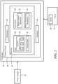
- FIG. 2 shows an example control circuit 38 coupled to the blood pump 10 including hardware and software for monitoring and controlling startup and subsequent operation of one or both of the stators 26 and 28 according to the routines of the present disclosure.
- the control circuit 38 includes a processor 42, a memory 44, and an interface 46 for interfacing with the motor 36.
- the memory 44 stores information accessible by the processor 42, including instructions 48 that may be executed by the processor 42.
- the memory 44 also includes data 50 that may be retrieved, manipulated or stored by the processor 42. Further details associated with the control circuit 38 are provided in commonly owned and co-pending U.S. Application No. 15/710323 .
- the instructions 48 stored in the memory 44 may include one or more instruction sets or modules, for performing certain operations in accordance with the present disclosure.
- One such module may be a motor control module 52 for controlling operation of the motor 36 (e.g., increasing or decreasing current supplied to the motor).
- the instructions may also include one or more motor monitor modules 54 for monitoring operation of the motor 36. Examples of motor control and monitoring modules may be found in any of the commonly owned and co-pending U.S. Application Serial Nos. 13/355,297 , 13/951,302 , 14/294,448 , 14/950,467 , 62/266,871 , and 62/271,618 .
- a startup routine 56 may be executed by the control circuit 38 of FIG. 2 , or by a similarly capable control circuit coupled to the controller 34.
- the startup routine 56 generates a relatively higher amount of initial torque than that which may be produced during one or more alternative startup routines.
- the startup routine 56 may be activated after a failure of another startup routine and thus may be referred to as a secondary startup routine.
- the startup routines disclosed herein are configured to displace the impeller 20 from a starting position at rest, in which the impeller 20 is in contact with the first disk 22 and/or the second disk 24, to an operating position in which the impeller 20 is suspended within the housing 12 to impel the blood.
- the startup routine 56 begins at step 58 with the control circuit 38 instructing the motor 36 to gradually increase a motor speed during a ramp phase from an inactive state, including a speed of zero when the impeller 20 is at rest, to an operating speed.
- the control circuit 38 applies a predetermined maximum voltage, creating high torque to overcome friction or coagulated blood that may hinder the movement of the impeller 20.
- the control circuit 38 transitions or switches from the gradual increase in motor speed to a closed-loop speed control to achieve the operating speed in which the blood pump operates in a normal mode.
- the closed-loop speed control may be performed by the control circuit 38 of the controller ( FIG. 2 ).
- the motor speed may be maintained by adjusting a voltage according to a speed difference produced by the torque.
- the transition to closed-loop control may cause an overshoot in the motor speed in which the motor speed increases from a first speed to an overshoot speed greater than the operating speed.
- an overshoot of the operating speed may inadvertently occur. This overshoot may be minimized by appropriate tuning of the closed-loop speed-control parameters.
- a speed waveform "SP" is depicted in a solid line illustrating the gradual increase in motor speed from an initial speed 64 of zero in the inactive state to the first speed 66.
- the first speed 66 may be between 250 to 600 RPM, such as 480 RPM, or as otherwise preprogrammed in accordance with the pump parameters.
- the term "gradual” includes the speed change occurring within a first-time period 68, such as 2 to 3 seconds. During the first-time period 68, the speed waveform is produced as a non-linear frequency ramp.
- the control circuit 38 may include a timer or timing mechanism configured to control the changes in timing of the motor speed.
- the predetermined maximum voltage is applied during the ramp phase of the startup routine 56.
- the predetermined maximum voltage has a corresponding torque output that is relatively high in comparison to the amount of torque existing in other phases of the motor startup.
- the voltage is increased from zero to the predetermined maximum voltage during the first-time period 68 beginning with initial activation.
- the predetermined maximum voltage may be between 10 to 14V and the first-time period 68 may be under one second.
- the controller 34 may be programmed to maintain the voltage below a predetermined maximum voltage threshold, such as 14V, or as otherwise designated.
- the increase in the motor speed may result in a speed phase that directly follows the ramp phase, thereby bypassing a commutation phase.
- the startup routine 56 is executed without incrementally ramping the motor voltage and searching for or measuring back electromotive force, i.e., "BEMF” or "Back-EMF,” signals indicating impeller motion or positioning, as is commonly found during the commutation phase.
- the speed phase may include the overshoot and may occur during a second-time period 72 less than the first-time period 68, such as less than one second, for example between 0.25 to 0.75 seconds.
- the motor speed increases at a faster rate in the speed phase when compared to the speed increase in the ramp phase.
- Ordinary operation of the motor 36 may commence when the motor 36 reaches the operating speed 74, such as between 1800 to 4000 RPM.
- the ramp and speed phases, including the motor speed transition from the initial speed of zero to the operating speed 74 occur over a startup time duration that is less than 8 seconds, such as between 3-4 seconds.
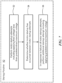
- the control circuit 38 or a similarly capable control circuit coupled to the controller 34 performs a startup routine 76 including detecting an electrical fault in the first stator 26 or the second stator 28.
- the startup routine 76 may be referred to as a 5-wire start.
- the startup routine 76 begins at step 78 with detecting the electrical fault, for example, in the second stator 28, such as using the control circuit 38.
- startup of the first stator 26 and the second stator 28 are commenced, such as by applying a voltage thereto from the power supply, in response to the electrical fault condition. In other words, despite the presence of the electrical fault condition, both stators are started.
- closed-loop control of the motor may be commenced including the non-faulty stator being used for monitoring BEMF.
- the electrical fault may be detected after startup is completed, such as when the stators are running at the operating speed in the normal operative mode. Detection of the electrical fault in the second stator 28 is provided for illustrative purposes only as the electrical fault condition may exist in either stator.
- FIG. 6 further details associated with the startup routine 76 are depicted including the power supply 32 and the controller 34 being in communication with the first stator 26 having the three motor windings 84 and the second stator 28 having the three motor windings 86 on opposing sides of the impeller 20.
- the controller 34 commences startup of the first stator 26 by driving the three motor windings 84 using voltage and current from the power supply 32 such that the first stator 26 operates in the three phases, e.g., U, V, W.
- the first stator 26 operates in the three phases, e.g., U, V, W.
- the first stator 26 generates a predetermined amount of axial force and radial torque for rotating and suspending the impeller 20.
- the controller 34 may detect the electrical fault condition, such as a continuity loss 88 in one or more of the motor windings 86 of the second stator 28. Despite the electrical fault condition, the controller 34 may commence the startup of the second stator 28 such that the second stator 28 operates in a set of two phases, thereby providing a five-wire start between the combined stators 26, 28. Commencing startup of the second stator 28, even in the presence of the electrical fault condition, generates a greater amount of axial force and radial torque than that which is generated using only a single stator to increase the likelihood of a successful startup.
- the electrical fault condition such as a continuity loss 88 in one or more of the motor windings 86 of the second stator 28.
- the successful startup includes the impeller 20 being rotated and suspended within the housing 12 to impel the blood in a normal operative mode.
- the first stator 26 and the second stator 28 may be configured to continue operating in the normal operative mode at the operating speed despite the presence of the electrical fault condition.
- the two operating phases of the second stator 28, or faulty stator may vary in accordance with the location of the continuity loss 88 with respect to the coils in an effort to rotate and suspend the impeller 20.
- the phase angle of the first stator 26 and/or the second stator 28 with respect to the housing 12 may be altered depending upon the location of the faulty stator within the housing 12, e.g., proximate the first disk 22 or the second disk 24, and the location of the electrical fault condition.
- the control circuit 38 may alter the wire phase of the first stator 26 and/or the second stator 28 to alter the phase angle and vary the torque in an effort to rotate the impeller 20.
- the control circuit 38 or a similarly capable control circuit coupled to the controller 34 performs a startup routine 90 in which a first voltage is applied to the stators 26, 28, that is less than a predetermined maximum voltage.
- the predetermined maximum voltage is the predetermined maximum voltage that is below the predetermined maximum voltage threshold discussed above with respect to the startup routine 56.
- the startup routine 90 attempts the motor startup using an amount of torque less than the amount of torque initially generated during the startup routine 56 in an attempt to decrease the risk of harm to the patient that may occur with the higher amount of torque.
- the startup routine 90 may be referred to as a primary startup routine with the startup routine 56 being the secondary startup routine.
- the startup routine 90 begins at step 92 with a first motor startup attempt including applying a first voltage to both stators 26, 28, such as from the power supply 32. If unsuccessful, the control circuit 38 executes a second startup attempt in the manner described with respect to the first startup attempt. In one configuration, two startup attempts are performed with an interval of 2 to 3 seconds therebetween; however, other configurations may include a single startup attempt and/or more than two startup attempts with a shorter or longer interval therebetween.
- the control circuit 38 detects whether the motor 36 was successfully started. In response to a failure of the motor startup attempts, at step 96, the control circuit 38 performs an additional startup attempt using the startup routine 56.
- the additional startup attempt includes applying the predetermined maximum voltage, which is greater than the first voltage, to the stators 26, 28, and implementing the speed ramp of the startup routine 56.
- the first and second motor startup attempts include applying the first voltage, depicted using the voltage current waveform "VC2," to the first stator 26 and/or the second stator 28 during a first-time period.
- the first voltage is between 8 to 12V and the first-time period includes the first stator 26 and the second stator 28 being in the inactive state.
- the first voltage and the predetermined maximum voltage may be stored in the memory of the controller 34.
- the first voltage may increase from zero to a range below the predetermined maximum voltage threshold in less than one second.
- the motor speed depicted using a speed waveform "SP2" shown in a solid line, will undergo stepwise changes during the ramp phase, a commutation phase, and a speed phase that may exceed a startup duration of more than 10 seconds. Whether or not the startup is successful may be determined through one or more methods, such as the control circuit 38 attempting to search for and/or measure the BEMF signals indicating the motion or positioning of the impeller 20
- the additional startup attempt is the startup routine 56 which includes applying the predetermined maximum voltage, such as 14V, to the first stator 26 and/or the second stator 28 from the inactive state and transitioning the motor speed from the ramp phase directly to the speed phase to the exclusion of the commutation phase.
- the predetermined maximum voltage such as 14V
- an alternative amount of voltage may be used during another type of startup routine.
Landscapes
- Health & Medical Sciences (AREA)
- Engineering & Computer Science (AREA)
- Heart & Thoracic Surgery (AREA)
- Cardiology (AREA)
- Mechanical Engineering (AREA)
- Biomedical Technology (AREA)
- Anesthesiology (AREA)
- Hematology (AREA)
- Life Sciences & Earth Sciences (AREA)
- Animal Behavior & Ethology (AREA)
- General Health & Medical Sciences (AREA)
- Public Health (AREA)
- Veterinary Medicine (AREA)
- General Engineering & Computer Science (AREA)
- External Artificial Organs (AREA)
Claims (9)
- Circuit de commande (38) pour une pompe à sang implantable (10), le circuit de commande (38) étant couplé à la pompe à sang implantable (10) et comportant des circuits de traitement comprenant un ou plusieurs processeurs (42), le circuit de commande étant caractérisé en ce que le ou les processeurs (42) sont configurés pour :augmenter progressivement une vitesse du moteur depuis un état inactif jusqu'à une première vitesse (66) pendant une première période temporelle (68) ;appliquer une tension maximale prédéterminée pendant l'augmentation progressive de la vitesse du moteur ; eteffectuer une transition depuis l'augmentation progressive de la vitesse du moteur vers une commande de vitesse en boucle fermée pour atteindre une vitesse de fonctionnement (74), la vitesse de fonctionnement (74) étant supérieure à la première vitesse (66).
- Circuit de commande selon la revendication 1, le ou les processeurs (42) étant configurés en outre pour contourner une phase de commutation.
- Circuit de commande selon la revendication 1, le ou les processeurs (42) étant configurés en outre pour maintenir une tension en dessous d'un seuil de tension maximale prédéterminé.
- Circuit de commande selon la revendication 3, une transition de la vitesse du moteur depuis l'état inactif jusqu'à la vitesse de fonctionnement (74) se produisant sur une durée de démarrage inférieure à 8 secondes.
- Circuit de commande selon la revendication 4, le ou les processeurs (42) étant configurés en outre pour déplacer une roue à aubes (20) de la pompe à sang (10) depuis une position de départ dans laquelle la roue à aubes (20) est en contact avec un disque (22, 24) vers une position de fonctionnement dans laquelle la roue à aubes (20) est déplacée à l'écart du disque (22, 24).
- Circuit de commande selon la revendication 1, le ou les processeurs (42) étant configurés en outre pour générer une rampe de fréquence non linéaire lors de l'augmentation progressive de la vitesse du moteur depuis l'état inactif jusqu'à la première vitesse (66).
- Circuit de commande selon la revendication 1, le ou les processeurs (42) étant configurés en outre pour appliquer une tension maximale prédéterminée à une pluralité de bobines d'un stator (26, 28) disposé dans la pompe à sang implantable (10) lors de l'augmentation progressive de la vitesse du moteur depuis l'état inactif jusqu'à la première vitesse (66).
- Circuit de commande selon la revendication 1, l'état inactif comprenant une vitesse nulle et la première vitesse (66) étant comprise entre 100 et 2 000 tr/min.
- Circuit de commande selon la revendication 1, la première période temporelle (68) étant comprise entre 2 et 3 secondes et la seconde période temporelle (72) étant inférieure à une seconde.
Priority Applications (1)
| Application Number | Priority Date | Filing Date | Title |
|---|---|---|---|
| EP24209246.8A EP4541411A1 (fr) | 2018-09-19 | 2019-08-27 | Procédé de démarrage d'une pompe à sang avec un défaut électrique |
Applications Claiming Priority (2)
| Application Number | Priority Date | Filing Date | Title |
|---|---|---|---|
| US201862733338P | 2018-09-19 | 2018-09-19 | |
| PCT/US2019/048222 WO2020060726A1 (fr) | 2018-09-19 | 2019-08-27 | Procédé de démarrage d'une pompe à sang avec un défaut électrique |
Related Child Applications (2)
| Application Number | Title | Priority Date | Filing Date |
|---|---|---|---|
| EP24209246.8A Division-Into EP4541411A1 (fr) | 2018-09-19 | 2019-08-27 | Procédé de démarrage d'une pompe à sang avec un défaut électrique |
| EP24209246.8A Division EP4541411A1 (fr) | 2018-09-19 | 2019-08-27 | Procédé de démarrage d'une pompe à sang avec un défaut électrique |
Publications (3)
| Publication Number | Publication Date |
|---|---|
| EP3852832A1 EP3852832A1 (fr) | 2021-07-28 |
| EP3852832B1 true EP3852832B1 (fr) | 2024-12-04 |
| EP3852832B8 EP3852832B8 (fr) | 2025-01-15 |
Family
ID=67902633
Family Applications (2)
| Application Number | Title | Priority Date | Filing Date |
|---|---|---|---|
| EP19765888.3A Active EP3852832B8 (fr) | 2018-09-19 | 2019-08-27 | Procédé de démarrage d'une pompe à sang avec un défaut électrique |
| EP24209246.8A Pending EP4541411A1 (fr) | 2018-09-19 | 2019-08-27 | Procédé de démarrage d'une pompe à sang avec un défaut électrique |
Family Applications After (1)
| Application Number | Title | Priority Date | Filing Date |
|---|---|---|---|
| EP24209246.8A Pending EP4541411A1 (fr) | 2018-09-19 | 2019-08-27 | Procédé de démarrage d'une pompe à sang avec un défaut électrique |
Country Status (4)
| Country | Link |
|---|---|
| US (1) | US20200086023A1 (fr) |
| EP (2) | EP3852832B8 (fr) |
| CN (2) | CN119868791A (fr) |
| WO (1) | WO2020060726A1 (fr) |
Families Citing this family (1)
| Publication number | Priority date | Publication date | Assignee | Title |
|---|---|---|---|---|
| CN110947040A (zh) * | 2019-12-18 | 2020-04-03 | 山东大学 | 一种体外循环血泵及方法 |
Citations (1)
| Publication number | Priority date | Publication date | Assignee | Title |
|---|---|---|---|---|
| US20170185054A1 (en) * | 2015-12-28 | 2017-06-29 | Heartware, Inc. | Pump motor control with adaptive startup |
Family Cites Families (15)
| Publication number | Priority date | Publication date | Assignee | Title |
|---|---|---|---|---|
| GB1026682A (en) * | 1962-03-30 | 1966-04-20 | English Electric Co Ltd | Electric motor speed control systems |
| DE4031398A1 (de) * | 1990-10-04 | 1992-04-09 | Digital Equipment Int | Verfahren und schaltung zur regelung der drehgeschwindigkeit eines gleichstrommotors |
| EP0989656B1 (fr) * | 1998-09-24 | 2009-03-11 | Levitronix LLC | Entraînement de rotation à excitation par aimants permanents |
| DE19936755A1 (de) * | 1999-08-09 | 2001-02-15 | Wilo Gmbh | Verfahren zum Starten von Brushless DC-Motoren |
| TW487094U (en) * | 2000-07-10 | 2002-05-11 | Universal Scient Ind Co Ltd | Motor controller for electric motorcycle |
| US8540493B2 (en) * | 2003-12-08 | 2013-09-24 | Sta-Rite Industries, Llc | Pump control system and method |
| GB0415511D0 (en) * | 2004-07-10 | 2004-08-11 | Trw Ltd | Motor drive voltage-boost control |
| EP3954901A1 (fr) * | 2006-01-13 | 2022-02-16 | HeartWare, Inc. | Pompe sanguine rotative |
| CN102239334B (zh) * | 2008-12-08 | 2015-03-04 | 胸腔科技有限公司 | 离心式泵装置 |
| US8405332B1 (en) * | 2009-02-24 | 2013-03-26 | Marvell International Ltd. | Method to eliminate current surge during spindle spin up |
| TW201212959A (en) * | 2010-06-22 | 2012-04-01 | Thoratec Corp | Fluid delivery system and method for monitoring fluid delivery system |
| WO2013056131A1 (fr) * | 2011-10-13 | 2013-04-18 | Reichenbach Steven H | Pompe et procédé de pompage de sang à débit mélangé |
| US9556873B2 (en) * | 2013-02-27 | 2017-01-31 | Tc1 Llc | Startup sequence for centrifugal pump with levitated impeller |
| US10426879B2 (en) * | 2015-12-14 | 2019-10-01 | Heartware, Inc. | Blood pump with restart lockout |
| EP3515526A1 (fr) * | 2016-09-23 | 2019-07-31 | Heartware, Inc. | Commande vectorielle pour commander un moteur de pompe à sang |
-
2019
- 2019-08-27 CN CN202510016736.6A patent/CN119868791A/zh active Pending
- 2019-08-27 WO PCT/US2019/048222 patent/WO2020060726A1/fr not_active Ceased
- 2019-08-27 EP EP19765888.3A patent/EP3852832B8/fr active Active
- 2019-08-27 EP EP24209246.8A patent/EP4541411A1/fr active Pending
- 2019-08-27 CN CN201980061230.XA patent/CN112714661B/zh active Active
- 2019-08-27 US US16/551,833 patent/US20200086023A1/en not_active Abandoned
Patent Citations (1)
| Publication number | Priority date | Publication date | Assignee | Title |
|---|---|---|---|---|
| US20170185054A1 (en) * | 2015-12-28 | 2017-06-29 | Heartware, Inc. | Pump motor control with adaptive startup |
Also Published As
| Publication number | Publication date |
|---|---|
| US20200086023A1 (en) | 2020-03-19 |
| WO2020060726A1 (fr) | 2020-03-26 |
| EP4541411A1 (fr) | 2025-04-23 |
| CN112714661B (zh) | 2025-01-28 |
| EP3852832B8 (fr) | 2025-01-15 |
| EP3852832A1 (fr) | 2021-07-28 |
| CN112714661A (zh) | 2021-04-27 |
| CN119868791A (zh) | 2025-04-25 |
Similar Documents
| Publication | Publication Date | Title |
|---|---|---|
| US11977357B2 (en) | Pump motor control with adaptive startup | |
| US11969588B2 (en) | Blood pump with impeller rinse operation | |
| EP2961984B1 (fr) | Séquence de démarrage pour pompe centrifuge à roue-hélice soulevée par lévitation | |
| EP3790606B1 (fr) | Algorithme de pression de pompe axiale à commande orientée de champ | |
| EP3852832B1 (fr) | Procédé de démarrage d'une pompe à sang avec un défaut électrique | |
| WO2021076267A1 (fr) | Pompe pulsatile avec élément actif et rinçage de thrombus | |
| US12156745B2 (en) | Detection of hypertension in LVAD patients using speed change | |
| US20260097195A1 (en) | Motor drive circuit for a mechanical circulatory support device | |
| CN119147957A (zh) | 电机故障检测方法及装置 |
Legal Events
| Date | Code | Title | Description |
|---|---|---|---|
| STAA | Information on the status of an ep patent application or granted ep patent |
Free format text: STATUS: UNKNOWN |
|
| STAA | Information on the status of an ep patent application or granted ep patent |
Free format text: STATUS: THE INTERNATIONAL PUBLICATION HAS BEEN MADE |
|
| PUAI | Public reference made under article 153(3) epc to a published international application that has entered the european phase |
Free format text: ORIGINAL CODE: 0009012 |
|
| STAA | Information on the status of an ep patent application or granted ep patent |
Free format text: STATUS: REQUEST FOR EXAMINATION WAS MADE |
|
| 17P | Request for examination filed |
Effective date: 20210413 |
|
| AK | Designated contracting states |
Kind code of ref document: A1 Designated state(s): AL AT BE BG CH CY CZ DE DK EE ES FI FR GB GR HR HU IE IS IT LI LT LU LV MC MK MT NL NO PL PT RO RS SE SI SK SM TR |
|
| DAV | Request for validation of the european patent (deleted) | ||
| DAX | Request for extension of the european patent (deleted) | ||
| REG | Reference to a national code |
Ref country code: DE Ref legal event code: R079 Free format text: PREVIOUS MAIN CLASS: A61M0001100000 Ipc: A61M0060178000 Ref country code: DE Ref legal event code: R079 Ref document number: 602019062993 Country of ref document: DE Free format text: PREVIOUS MAIN CLASS: A61M0001100000 Ipc: A61M0060178000 |
|
| GRAP | Despatch of communication of intention to grant a patent |
Free format text: ORIGINAL CODE: EPIDOSNIGR1 |
|
| STAA | Information on the status of an ep patent application or granted ep patent |
Free format text: STATUS: GRANT OF PATENT IS INTENDED |
|
| RIC1 | Information provided on ipc code assigned before grant |
Ipc: A61M 60/538 20210101ALI20240603BHEP Ipc: A61M 60/422 20210101ALI20240603BHEP Ipc: A61M 60/232 20210101ALI20240603BHEP Ipc: A61M 60/178 20210101AFI20240603BHEP |
|
| INTG | Intention to grant announced |
Effective date: 20240701 |
|
| GRAS | Grant fee paid |
Free format text: ORIGINAL CODE: EPIDOSNIGR3 |
|
| GRAA | (expected) grant |
Free format text: ORIGINAL CODE: 0009210 |
|
| STAA | Information on the status of an ep patent application or granted ep patent |
Free format text: STATUS: THE PATENT HAS BEEN GRANTED |
|
| AK | Designated contracting states |
Kind code of ref document: B1 Designated state(s): AL AT BE BG CH CY CZ DE DK EE ES FI FR GB GR HR HU IE IS IT LI LT LU LV MC MK MT NL NO PL PT RO RS SE SI SK SM TR |
|
| REG | Reference to a national code |
Ref country code: CH Ref legal event code: EP |
|
| REG | Reference to a national code |
Ref country code: DE Ref legal event code: R081 Ref document number: 602019062993 Country of ref document: DE Owner name: BOSTON SCIENTIFIC SCIMED, INC., MAPLE GROVE, US Free format text: FORMER OWNER: HEARTWARE, INC., MIAMI LAKES, FL, US |
|
| REG | Reference to a national code |
Ref country code: DE Ref legal event code: R096 Ref document number: 602019062993 Country of ref document: DE |
|
| REG | Reference to a national code |
Ref country code: CH Ref legal event code: PK Free format text: BERICHTIGUNG B8 |
|
| REG | Reference to a national code |
Ref country code: IE Ref legal event code: FG4D |
|
| RAP2 | Party data changed (patent owner data changed or rights of a patent transferred) |
Owner name: BOSTON SCIENTIFIC SCIMED, INC. |
|
| REG | Reference to a national code |
Ref country code: NL Ref legal event code: FP |
|
| REG | Reference to a national code |
Ref country code: LT Ref legal event code: MG9D |
|
| PG25 | Lapsed in a contracting state [announced via postgrant information from national office to epo] |
Ref country code: HR Free format text: LAPSE BECAUSE OF FAILURE TO SUBMIT A TRANSLATION OF THE DESCRIPTION OR TO PAY THE FEE WITHIN THE PRESCRIBED TIME-LIMIT Effective date: 20241204 |
|
| PG25 | Lapsed in a contracting state [announced via postgrant information from national office to epo] |
Ref country code: FI Free format text: LAPSE BECAUSE OF FAILURE TO SUBMIT A TRANSLATION OF THE DESCRIPTION OR TO PAY THE FEE WITHIN THE PRESCRIBED TIME-LIMIT Effective date: 20241204 |
|
| PG25 | Lapsed in a contracting state [announced via postgrant information from national office to epo] |
Ref country code: BG Free format text: LAPSE BECAUSE OF FAILURE TO SUBMIT A TRANSLATION OF THE DESCRIPTION OR TO PAY THE FEE WITHIN THE PRESCRIBED TIME-LIMIT Effective date: 20241204 |
|
| PG25 | Lapsed in a contracting state [announced via postgrant information from national office to epo] |
Ref country code: ES Free format text: LAPSE BECAUSE OF FAILURE TO SUBMIT A TRANSLATION OF THE DESCRIPTION OR TO PAY THE FEE WITHIN THE PRESCRIBED TIME-LIMIT Effective date: 20241204 |
|
| PG25 | Lapsed in a contracting state [announced via postgrant information from national office to epo] |
Ref country code: NO Free format text: LAPSE BECAUSE OF FAILURE TO SUBMIT A TRANSLATION OF THE DESCRIPTION OR TO PAY THE FEE WITHIN THE PRESCRIBED TIME-LIMIT Effective date: 20250304 |
|
| PG25 | Lapsed in a contracting state [announced via postgrant information from national office to epo] |
Ref country code: GR Free format text: LAPSE BECAUSE OF FAILURE TO SUBMIT A TRANSLATION OF THE DESCRIPTION OR TO PAY THE FEE WITHIN THE PRESCRIBED TIME-LIMIT Effective date: 20250305 Ref country code: LV Free format text: LAPSE BECAUSE OF FAILURE TO SUBMIT A TRANSLATION OF THE DESCRIPTION OR TO PAY THE FEE WITHIN THE PRESCRIBED TIME-LIMIT Effective date: 20241204 |
|
| PG25 | Lapsed in a contracting state [announced via postgrant information from national office to epo] |
Ref country code: RS Free format text: LAPSE BECAUSE OF FAILURE TO SUBMIT A TRANSLATION OF THE DESCRIPTION OR TO PAY THE FEE WITHIN THE PRESCRIBED TIME-LIMIT Effective date: 20250304 |
|
| REG | Reference to a national code |
Ref country code: AT Ref legal event code: MK05 Ref document number: 1747502 Country of ref document: AT Kind code of ref document: T Effective date: 20241204 |
|
| PG25 | Lapsed in a contracting state [announced via postgrant information from national office to epo] |
Ref country code: SM Free format text: LAPSE BECAUSE OF FAILURE TO SUBMIT A TRANSLATION OF THE DESCRIPTION OR TO PAY THE FEE WITHIN THE PRESCRIBED TIME-LIMIT Effective date: 20241204 |
|
| PG25 | Lapsed in a contracting state [announced via postgrant information from national office to epo] |
Ref country code: PL Free format text: LAPSE BECAUSE OF FAILURE TO SUBMIT A TRANSLATION OF THE DESCRIPTION OR TO PAY THE FEE WITHIN THE PRESCRIBED TIME-LIMIT Effective date: 20241204 |
|
| PG25 | Lapsed in a contracting state [announced via postgrant information from national office to epo] |
Ref country code: IS Free format text: LAPSE BECAUSE OF FAILURE TO SUBMIT A TRANSLATION OF THE DESCRIPTION OR TO PAY THE FEE WITHIN THE PRESCRIBED TIME-LIMIT Effective date: 20250404 |
|
| PG25 | Lapsed in a contracting state [announced via postgrant information from national office to epo] |
Ref country code: PT Free format text: LAPSE BECAUSE OF FAILURE TO SUBMIT A TRANSLATION OF THE DESCRIPTION OR TO PAY THE FEE WITHIN THE PRESCRIBED TIME-LIMIT Effective date: 20250404 |
|
| PG25 | Lapsed in a contracting state [announced via postgrant information from national office to epo] |
Ref country code: AT Free format text: LAPSE BECAUSE OF FAILURE TO SUBMIT A TRANSLATION OF THE DESCRIPTION OR TO PAY THE FEE WITHIN THE PRESCRIBED TIME-LIMIT Effective date: 20241204 Ref country code: RO Free format text: LAPSE BECAUSE OF FAILURE TO SUBMIT A TRANSLATION OF THE DESCRIPTION OR TO PAY THE FEE WITHIN THE PRESCRIBED TIME-LIMIT Effective date: 20241204 |
|
| PG25 | Lapsed in a contracting state [announced via postgrant information from national office to epo] |
Ref country code: SK Free format text: LAPSE BECAUSE OF FAILURE TO SUBMIT A TRANSLATION OF THE DESCRIPTION OR TO PAY THE FEE WITHIN THE PRESCRIBED TIME-LIMIT Effective date: 20241204 |
|
| PG25 | Lapsed in a contracting state [announced via postgrant information from national office to epo] |
Ref country code: CZ Free format text: LAPSE BECAUSE OF FAILURE TO SUBMIT A TRANSLATION OF THE DESCRIPTION OR TO PAY THE FEE WITHIN THE PRESCRIBED TIME-LIMIT Effective date: 20241204 |
|
| PG25 | Lapsed in a contracting state [announced via postgrant information from national office to epo] |
Ref country code: IT Free format text: LAPSE BECAUSE OF FAILURE TO SUBMIT A TRANSLATION OF THE DESCRIPTION OR TO PAY THE FEE WITHIN THE PRESCRIBED TIME-LIMIT Effective date: 20241204 |
|
| PGFP | Annual fee paid to national office [announced via postgrant information from national office to epo] |
Ref country code: NL Payment date: 20250723 Year of fee payment: 7 |
|
| REG | Reference to a national code |
Ref country code: DE Ref legal event code: R097 Ref document number: 602019062993 Country of ref document: DE |
|
| PG25 | Lapsed in a contracting state [announced via postgrant information from national office to epo] |
Ref country code: SE Free format text: LAPSE BECAUSE OF FAILURE TO SUBMIT A TRANSLATION OF THE DESCRIPTION OR TO PAY THE FEE WITHIN THE PRESCRIBED TIME-LIMIT Effective date: 20241204 |
|
| PG25 | Lapsed in a contracting state [announced via postgrant information from national office to epo] |
Ref country code: DK Free format text: LAPSE BECAUSE OF FAILURE TO SUBMIT A TRANSLATION OF THE DESCRIPTION OR TO PAY THE FEE WITHIN THE PRESCRIBED TIME-LIMIT Effective date: 20241204 |
|
| PGFP | Annual fee paid to national office [announced via postgrant information from national office to epo] |
Ref country code: DE Payment date: 20250724 Year of fee payment: 7 |
|
| PLBE | No opposition filed within time limit |
Free format text: ORIGINAL CODE: 0009261 |
|
| STAA | Information on the status of an ep patent application or granted ep patent |
Free format text: STATUS: NO OPPOSITION FILED WITHIN TIME LIMIT |
|
| REG | Reference to a national code |
Ref country code: CH Ref legal event code: L10 Free format text: ST27 STATUS EVENT CODE: U-0-0-L10-L00 (AS PROVIDED BY THE NATIONAL OFFICE) Effective date: 20251015 |
|
| PGFP | Annual fee paid to national office [announced via postgrant information from national office to epo] |
Ref country code: IE Payment date: 20250725 Year of fee payment: 7 |
|
| 26N | No opposition filed |
Effective date: 20250905 |
|
| REG | Reference to a national code |
Ref country code: CH Ref legal event code: H13 Free format text: ST27 STATUS EVENT CODE: U-0-0-H10-H13 (AS PROVIDED BY THE NATIONAL OFFICE) Effective date: 20260324 |
|
| PG25 | Lapsed in a contracting state [announced via postgrant information from national office to epo] |
Ref country code: MC Free format text: LAPSE BECAUSE OF FAILURE TO SUBMIT A TRANSLATION OF THE DESCRIPTION OR TO PAY THE FEE WITHIN THE PRESCRIBED TIME-LIMIT Effective date: 20241204 |
|
| PG25 | Lapsed in a contracting state [announced via postgrant information from national office to epo] |
Ref country code: LU Free format text: LAPSE BECAUSE OF NON-PAYMENT OF DUE FEES Effective date: 20250827 |
|
| PG25 | Lapsed in a contracting state [announced via postgrant information from national office to epo] |
Ref country code: CH Free format text: LAPSE BECAUSE OF NON-PAYMENT OF DUE FEES Effective date: 20250831 |